EP1724610B1 - Verfahren zur Messung der Totzeit eines Röntgenstrahlendetektors - Google Patents
Verfahren zur Messung der Totzeit eines Röntgenstrahlendetektors Download PDFInfo
- Publication number
- EP1724610B1 EP1724610B1 EP06010412A EP06010412A EP1724610B1 EP 1724610 B1 EP1724610 B1 EP 1724610B1 EP 06010412 A EP06010412 A EP 06010412A EP 06010412 A EP06010412 A EP 06010412A EP 1724610 B1 EP1724610 B1 EP 1724610B1
- Authority
- EP
- European Patent Office
- Prior art keywords
- ray
- condition
- observed
- obs
- intensity
- Prior art date
- Legal status (The legal status is an assumption and is not a legal conclusion. Google has not performed a legal analysis and makes no representation as to the accuracy of the status listed.)
- Not-in-force
Links
Images


Classifications
-
- G—PHYSICS
- G01—MEASURING; TESTING
- G01T—MEASUREMENT OF NUCLEAR OR X-RADIATION
- G01T1/00—Measuring X-radiation, gamma radiation, corpuscular radiation, or cosmic radiation
- G01T1/16—Measuring radiation intensity
- G01T1/17—Circuit arrangements not adapted to a particular type of detector
- G01T1/171—Compensation of dead-time counting losses
Definitions
- the present invention relates to a method for measuring the dead time of a pulse type X-ray detector.
- a pulse type X-ray detector including for example a proportional counter, a scintillation counter and a solid-state detector such as an avalanche photo diode, can detect an X-ray intensity by counting the number of X-ray photons, i.e., particles. Accordingly, the pulse type X-ray detector has, in principle, the disadvantage of counting loss based on the finite dead time.
- the pulse type X-ray detector has, in principle, the disadvantage of counting loss based on the finite dead time.
- the predetermined time described above has been referred to as the dead time.
- the dead time consists of a time inherent in a detecting device and another time comes from an electronic circuit such as a pulse height analyzer.
- the present application aims the dead time as viewed from the final output of the X-ray detector, i.e., the dead time in total of the X-ray detector.
- Equation (1) in Fig. 1 is a corrected expression of an X-ray detection intensity in an asphyxiant type X-ray detector which uses an amplifier.
- I obs indicates an X-ray intensity actually observed in the X-ray detector
- I tru indicates a true X-ray intensity having entered the X-ray detector
- ⁇ indicates the dead time.
- the unit of an X-ray intensity is the count number per unit of time, cps for example.
- Fig. 2 shows a graph of equation (1), I tru in abscissa and I obs in ordinate.
- a straight broken line 10 indicates that I obs is equal to I tru , this is the ideal state without counting loss, which means that the dead time is zero.
- the shape of equation (1) becomes a mound curve, I obs becoming maximum when I tru is equal to 1/ ⁇ .
- Equation (1) can be transformed so that I tru comes to the left side, resulting in equation (2) in Fig. 1 .
- This equation (2) is used to obtain a true X-ray intensity I tru with the use of an observed X-ray intensity I obs and the dead time ⁇ .
- the nested structure of exp in equation (2) continues infinitely. In an actual calculation, however, the number of nesting may be cut off at the predetermined number. If the predetermined number is large enough, a true X-ray intensity is obtained with a sufficient accuracy.
- Equation (3) indicates an approximate equation in which the number of nesting is cut off at three.
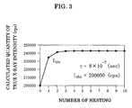
- Fig. 3 shows a graph indicating a variation of a calculated quantity of equation (2), i.e., a calculated true X-ray intensity I tru , with the number of nesting, provided that the calculation is carried out with two hundred thousand cps in observed X-ray intensity I obs and 8 ⁇ 10 -7 seconds in dead time ⁇ .
- the calculated quantity is convergent.
- about ten nesting would be sufficient because the good calculation result is obtained at ten nesting almost the same as that with the infinite nesting.
- the dead time ⁇ is known, a true X-ray intensity can be calculated with an observed X-ray intensity I obs as described. Then, it is important, in the counting loss correction, to determine the dead time ⁇ precisely.
- the conventional methods for determining the dead time is disclosed in, for example, (1) Elements of X-ray Diffraction, Second Edition, written by B. D. Cullity, Japanese Version, translated by G. Matsumura, published by Agune (Japan), 1980, page 181 (which will be referred to as the first publication hereinafter) and (2) Experimental Physics Course 20, X-ray Diffraction, edited by K. Kohra, published by Kyoritsu Shuppan (Japan), 1988, pages 147-148 (which will be referred to as the second publication hereinafter).
- the first publication discloses that (i) a plurality of metal foils having the same thickness are superimposed on one another to make an absorber, (ii) the absorber is inserted into the X-ray path, and (iii) X-ray intensities are detected with removing one metal foil after one detection. Plotting the number of the metal foils removed in abscissa while observed X-ray intensities (cps) in ordinate having a logarithmic scale, the logarithmic observed X-ray intensities are proportional to the removed numbers in a range of the smaller number of the removed metal foils, that is, in a range in which X-ray intensities are weak and thus there is almost no counting loss.
- the dead time can be determined in a manner that (i) an X-ray intensity is detected with a small tube current, the observed X-ray intensity being almost equal to the true X-ray intensity, (ii) another X-ray intensity is detected with a large tube current enough to raise the counting loss, (iii) a true X-ray intensity with the large tube current is estimated based on the proportional relationship between the tube current and the true X-ray intensity and (iv) the dead time is determined using the estimated true X-ray intensity and the observed X-ray intensity.
- the second publication introduces, as a method for determining the dead time experimentally, two books regarding the two-source method.
- an X-ray intensity entering the X-ray detector is definitely out of proportional to the tube current. Furthermore, it is necessary, for estimating a true X-ray intensity, to use an observed X-ray intensity which is obtained with a small tube current, and accordingly the resultant estimated high X-ray intensity would have a poor accuracy.
- the method according to the present invention is for measuring a dead time of a pulse type X-ray detector and comprises the steps as mentioned in claim 1.
- the first condition is preferably a variable which can be scanned smoothly and has a good repeatability.
- the second condition is so selected that the ratio of the received X-ray intensity in the second setting state to the received X-ray intensity in the first setting states becomes constant in any setting states of the first condition. It is also important that at least some part of combinations of the setting states of the first condition and the setting states of the second condition should provide a high X-ray intensity enough to raise the counting loss.
- the number of the setting states of the first condition is three or more. More increased the number of the setting states, more improved the determination accuracy of the dead time. It is ascertained, by the inventors' experiment, that even with three setting states for the first condition, the difference between the calculated observed X-ray intensity which is determined with the least squares method according to the present invention and the actual observed X-ray intensity falls within five percent. Therefore, the present invention functions effectively even with three setting states for the first condition. It is preferable, however, that the number of the setting states for the first condition may be increased for a higher accuracy of the dead time, preferably not smaller than ten, more preferably not smaller than a hundred.
- the first condition may be a state of a slit arranged in the X-ray path
- the second condition may be with or without an absorption plate inserted into the X-ray path.
- a variation of the state of the slit may be a variation of a slit width of a receiving slit, a transverse movement of a receiving slit with a constant slit width, a variation of a slit width of a divergence slit, or a transverse movement of a divergence slit with a constant slit width.
- the rocking curve of the diffraction peak of a perfect crystal may be used to measure the dead time.
- the first condition may be a variation in angle of any rotation in the diffraction optical path
- the second condition may be with or without an absorption plate inserted into the X-ray path.
- the any rotation in the diffraction optical path may be a 2 ⁇ -rotation which rotates the X-ray detector, or an ⁇ -rotation which rotates the perfect crystal.
- Equation (1) in Fig. 1 is, as having been described above, a corrected expression of an X-ray detection intensity in an asphyxiant type X-ray detector which uses an amplifier. Equation (1) is transformed to give equation (2), which is used to obtain a true X-ray intensity I tru with the use of an observed X-ray intensity I obs and the dead time ⁇ .
- Equation (2) is a function of the observed X-ray intensity I obs and the dead time ⁇ .
- equation (2) may be replaced by equation (4).
- the present invention observes an X-ray intensity with the X-ray detector for determining the dead time, and the observation process uses the first condition and the second condition.
- the first condition has at least three setting states, preferably not smaller than ten setting states, more preferably about a hundred setting states if possible.
- the second condition has two setting states.
- An observed X-ray intensity in the first setting state of the second condition will be referred to as the first observed X-ray intensity, and is expressed by I obs1 .
- an observed X-ray intensity in the second setting state of the second condition will be referred to as the second observed X-ray intensity, and is expressed by I obs2 .
- the first true X-ray intensity corresponding to the first observed X-ray intensity I obs1 is expressed by I tru1
- the second true X-ray intensity corresponding to the second observed X-ray intensity I obs2 is expressed by I tru2 .
- the first observed X-ray intensity I obs1 and the first true X-ray intensity I tru1 have a relationship expressed by equation (5), similar to equation (1).
- the second observed X-ray intensity I obs2 and the second true X-ray intensity I tru2 have a relationship expressed by equation (6).
- the second true X-ray intensity I tru2 is, as indicated by equation (7), proportional to the first true X-ray intensity I tru1 , the ratio of the former to the latter being expressed by k.
- the ratio k is constant in any setting states of the first condition. In other words, the two setting states of the second condition are selected so that the ratio k is constant in any setting states of the first condition. This feature is important in the present invention.
- Equation (9) is a relational expression defining a relationship between the four items: the first observed X-ray intensity I obs1 , the second observed X-ray intensity I obs2 , the ratio K, and the dead time ⁇ .
- the first observed X-ray intensity I obs1 and the second observed X-ray intensity I obs2 are actually observed quantities and thus are known.
- the ratio k and the dead time ⁇ are unknown and can be determined at the same time by the process described below. As a result, the dead time ⁇ can be determined precisely.
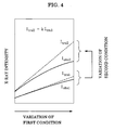
- Fig. 4 shows a graph indicating schematically a variation of the first condition, a variation of the second condition, and a variation of an X-ray intensity therewith.
- the second condition is set to the first setting state and X-ray intensities are observed by the X-ray detector with variation of the first condition, a series of the first observed X-ray intensities I obs1 are obtained.
- the first observed X-ray intensity I obs1 and the corresponding first true X-ray intensity I tru1 would vary as shown in Fig. 4 .
- the first setting state of the second condition is changed to the second setting state, and then, similar to in the first setting state, X-ray intensities are observed by the X-ray detector with variation of the first condition, the second observed X-ray intensities I obs2 being obtained.
- the second observed X-ray intensity I obs2 and the corresponding second true X-ray intensity I tru2 would vary as shown also in Fig. 4 .
- the X-ray intensity is higher in the second setting state of the second condition than in the first setting state, and accordingly, the effect of the counting loss is stronger in the second observed X-ray intensity I obs2 .
- the second observed X-ray intensity I obs2 is apart from the second true X-ray intensity I tru2 farther than in the first observed X-ray intensity I obs1 . It is important, in the present invention, that at least some part of combinations of the setting states of the first condition and the setting states of the second condition should provide a high X-ray intensity enough to raise the remarkable counting loss as shown in Fig. 4 .
- Figs. 5A and 5B are plan views of an X-ray optical system for performing the method according to the present invention.
- the second condition is with or without an absorption plate
- the first condition is a variation of the slit width of a receiving slit.
- the optical system has an X-ray source 12 and an X-ray detector 14, and there are arranged therebetween a divergence slit 16, an absorption plate 18 and a receiving slit 20.
- the divergence slit 16 regulates a divergence angle of an X-ray beam 19 from the X-ray source 12 and prevents unwanted scattered X-rays from entering an X-ray detecting system.
- the absorption plate 18 may be inserted into the X-ray path or may be removed from the X-ray path.
- the receiving slit 20 consists of two slit blades 22 and 24, each of which can move in a direction perpendicular to the X-ray path, i.e., in an up-and-down direction in Fig. 5A .
- the distance between the two slit blades 22 and 24 is a slit width W.
- the two slit blades 22 and 24 can move in opposite directions with an interlocking motion, so that the slit width W can be wider or narrower symmetrically.
- a variation of the slit width W corresponds to a variation of the setting state of the first condition in the present invention.
- a state in which the absorption plate 18 is inserted into the X-ray path i.e., the state shown in Fig. 5A
- a state in which the absorption plate 18 is inserted into the X-ray path i.e., the state shown in Fig. 5A
- another state in which the absorption plate 18 is removed from the X-ray path i.e., the state shown in Fig. 5B
- the absorption plate 18 When the absorption plate 18 is inserted into the X-ray path, an X-ray is partly absorbed by the absorption plate 18 so that the X-ray intensity is attenuated. By passing through the absorption plate 18, the X-ray intensity is attenuated to 1/k, noting that k corresponds to the "ratio of the received X-ray intensity in the second setting state to the received X-ray intensity in the first setting state" in the present invention.
- the absorption plate 18 is inserted into the X-ray path, and then a series of the first observed X-ray intensities I obs1 are observed with the X-ray detector 14 as described below.
- the slit width W is changed from W1 to Wn with an interval of ⁇ W, and a series of the first observed X-ray intensities I obs11 to I obs1n are observed with the n-kinds of slit widths.
- the absorption plate 18 is removed from the X-ray path, and then a series of the second observed X-ray intensities I obs2 are observed with the X-ray detector 14.
- the slit width W is changed from W1 to Wn with an interval of ⁇ W, and a series of the second observed X-ray intensities I obs21 to I obs2n are observed with the n-kinds of slit widths.
- Such an observation process is schematically shown in a graph in Fig. 6 .
- a variation of the slit width W is in abscissa, varying as W1, W2, W3, ..., Wn, noting that actually the slit width varies continuously and the X-ray intensities are observed with the predetermined interval of ⁇ W.
- An observed X-ray intensity is in ordinate.
- the first observed X-ray intensities are observed as I obs11 , I obs12 , I obs13 , ..., I obs1n
- the second observed X-ray intensities are observed as I obs21 , I obs22 , I obs23 , ..., I obs2n .
- repeatability of the slit width W is important.
- the present invention is based on the premise that the slit width W1 with which I obs11 is observed is equal to the slit width W1 with which I obs21 is observed.
- the X-ray diffraction apparatus used in the present invention has 0.5 micrometer in minimum resolution of the slit width of the receiving slit, and keeps the repeatability of the slit width control at least the same as the minimum resolution.
- n-kinds of relational expressions can be made up as shown in equations (10) in Fig. 7 .
- the ratio k and the dead time ⁇ are determined so that the equations (10) are most satisfied in total.
- the least squares method may be used to determine most probable k and ⁇ based on the equations (10). That is, (i) k and ⁇ are assumed by trial and error, (ii) the difference between the right side and the left side is calculated for each of the respective equations (10) with the assumed k and ⁇ , (iii) each difference is raised to the second power, (iv) sum of the squares is calculated, and (v) k and ⁇ are determined so that the sum of the squares becomes minimum.
- Fig. 8 shows a graph indicating the actually-detected first observed X-ray intensity I obs1 and the actually-detected second observed X-ray intensity I obs2 .
- the graph is obtained in a manner described below.
- An optical system used is similar to that shown in Fig. 5A , provided that a multilayer mirror and a four-crystal monochromator made of Ge (220) crystal are inserted between the X-ray source 12 and the divergence slit 16.
- the X-ray source 12 is a CuK ⁇ ray.
- the absorption plate 18 is an aluminum plate which is 0.1 mm in thickness.
- the X-ray detector 14 is a scintillation counter.
- the first condition is not a variation of the slit width W of the receiving slit 20 but a variation of the position of the receiving slit 20, i.e., a transverse movement.
- the whole of the receiving slit 20 is moved continuously in a bottom-to-top direction in Fig. 5A so that the center of the receiving slit 20, i.e., the center of the slit width W, varies within a range between zero and one millimeter, the time required for the movement being about one minute.
- the origin of the center of the receiving slit 20 is a position at which an X-ray intensity detected by the X-ray detector 14 becomes almost zero.
- the resultant ratio k was 10.32 and the resultant dead time ⁇ was 7.7 ⁇ 10 -7 second.
- the difference between the observed X-ray intensity and the calculated quantity in the most fitted state was within one percent for each observed point.
- the fitting operation with the least squares method can determine the dead time precisely and can also provide the difference in the fitting, with which the accuracy of the dead time can be verified.
- the method according to the present invention can determine the dead time precisely in a very shot time as compared with the conventional method which uses the estimated true X-ray intensity based on the tube current, noting that it takes about thirty minutes until the tube current becomes stable. Since the fitting operation with the least squares method is carried out based on the many observed X-ray intensities, accuracy in observed X-ray intensity at one observing point would not affect the result. Therefore, even if about 240 kinds of the observed X-ray intensities are obtained in one minute as described above, the dead time is determined with a high accuracy.
- the present invention is not limited to the specific condition setting but may adopt various types of condition setting. Modifications of the condition setting will be described below.
- Fig. 9A is a plan view of the X-ray optical system of the standard X-ray diffractometer.
- the plan view shows a state in which an X-ray beam 19 from an X-ray source 12 is detected directly by an X-ray detector 14.
- the X-ray beam 19 is emitted from the X-ray source 12, and passes through a divergence slit 16, an incident Soller slit 28, a receiving Soller slit 30 and a receiving slit 20, and then reaches the X-ray detector 14.
- the X-ray detector 14, the receiving Soller slit 30 and the receiving slit 20 can rotate with a 2 ⁇ -rotation along with a 2 ⁇ -turntable 32.
- the direct beam from the X-ray source 12 is detected.
- the absorption plate 18 is inserted into or removed from the incident-side of the receiving slit 20, there is realized the optical system shown in Figs. 5A and 5B .
- the second condition is an inserted state or a removed state of the absorption plate 18, i.e., with or without the absorption plate 18.
- the first condition is a variation of the slit width of the receiving slit 20.
- Modifications of the first condition may be the transverse movement of the receiving slit which has been described with reference to Fig. 8 , or may be the following.
- the receiving slit 20 may be constant in state while the divergence slit 16 may vary in state. Namely, the slit width of the divergence slit 16 may vary or the divergence slit 16 is moved in a direction perpendicular to the X-ray path with a constant slit width.
- the first condition may be a variation in angle of the 2 ⁇ -rotation of the 2 ⁇ -turntable 32 without change in state of the slit members. In this case, when the angle of the 2 ⁇ -rotation varies, the position of the receiving slit 20 and the position of the X-ray detector 14 vary with respect to the X-ray beam 19, so that the observed X-ray intensity varies.
- Modifications of the second condition may be height regulation of any one of the slit members instead of with or without the absorption plate.
- a part of the height of the incident Soller slit 28 or the receiving Soller slit 30 may be closed or opened, noting that the height direction is a direction perpendicular to the drawing sheet.
- the divergence slit 16 or the receiving slit 20 may be under the height regulation.
- the height regulation is applicable to the case in which the cross section of the X-ray beam 19 extends long in a direction perpendicular to the drawing sheet in Fig. 5A .
- the first condition may be all of the modifications described above.
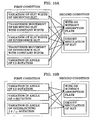
- a list of possible combinations of the first and second conditions are shown in Fig. 10A , any combination with a connecting line between one of the first conditions and one of the second conditions being a possible combination.
- the method according to the present invention may use the rocking curve of a diffraction peak of the perfect crystal.
- Fig. 9B is a plan view showing a condition in which a sample 34 made of the perfect crystal is mounted on a sample holder 36 to measure a rocking curve of the sample 34. Even with such a diffraction measurement, it is possible to determine the dead time according to the present invention.
- a rotation angle ⁇ of the sample holder 36 and a rotation angle 2 ⁇ of the 2 ⁇ -turntable 32 are set so that the specific diffraction peak of the perfect crystal sample 34 can be detected by the X-ray detector 14, and then the rotation angle 2 ⁇ of the 2 ⁇ -turntable 32 is scanned.
- Such a 2 ⁇ -scanning may be adopted as the first condition in the present invention.
- the second condition may be with or without the absorption plate 18, or the height regulation of any one of the slit members.
- Fig. 10B A list of such combinations is shown in Fig. 10B .
- the method according to the present invention can be performed, to determine the dead time, with the use of the X-ray optical system of the ordinary X-ray diffraction apparatus with almost no alterations, i.e., with the use of the movement mechanism of the slit and the rotational mechanism of the goniometer as they are.
- the ratio k is handled as unknown to determine the ratio k and the dead time ⁇
- the ratio k may be handled as known in the present invention.
- the attenuation rate in X-ray intensity by the absorption plate can be calculated with a high accuracy if the X-ray wavelength used is known and the material and the thickness of the absorption plate are known.
- the inverse number of such an attenuation rate may be used as the ratio k.
- the dead time ⁇ should be determined with the least squares method.
- the ratio k may be handled as known, if it is known, to determine the dead time ⁇ .
- the corrected expression of the observed X-ray intensity with the counting loss has the function form shown in equation (1)
- the present invention is not limited to the specific function form. Any function form may be used in the present invention provided that a true X-ray intensity I tru is calculated with the use of the dead time ⁇ and an observed X-ray intensity I obs .
Landscapes
- Physics & Mathematics (AREA)
- Health & Medical Sciences (AREA)
- Life Sciences & Earth Sciences (AREA)
- General Physics & Mathematics (AREA)
- High Energy & Nuclear Physics (AREA)
- Molecular Biology (AREA)
- Spectroscopy & Molecular Physics (AREA)
- Analysing Materials By The Use Of Radiation (AREA)
- Measurement Of Radiation (AREA)
Claims (10)
- Ein Verfahren zum Messen einer Totzeit T eines Pulstyp-Röntgendetektors (14), wobei das Verfahren die Folgenden Schritte aufweist:(a) Annehmen einer ersten Bedingung und einer zweiten Bedingung, wobei jede der beiden Bedingungen ein Merkmal aufweist, dass die Bedingung mehrere Zustände aufweist, die untereinander ausgetauscht werden können, so dass ein Zustand eines Röntgenpfades von einer Röntgenquelle (12) zu dem Röntgendetektor (14) geändert werden kann, um eine Intensität eines Röntgenstrahls, der in dem Röntgendetektor (14) empfangen wurde verändert werden kann;(b) Annehmen von wenigstens drei Einstellungszuständen für die erste Bedingung; und(c) Annehmen eines ersten Einstellungszustands und eines zweiten Einstellungszustands für die zweite Bedingung, so dass (c-1) die empfangene Röntgenstrahlintensität in dem ersten Einstellungszustand unterschiedlich ist zu der empfangenen Röntgenstrahlintensität in dem zweiten Einstellungszustand und (c-2) ein Verhältnis k der empfangenen Röntgenstrahlintensität in dem zweiten Einstellungszustand zu der empfangenen Röntgenstrahlintensität in dem ersten Einstellungszustand konstant in jedem der wenigstens drei Einstellungszustände der ersten Bedingung ist; und(d) Einstellen des ersten Einstellungszustands für die zweite Bedingung;(e) Ausführen eines ersten Beobachtungsschritts in dem ein Röntgenstrahl von der Röntgenquelle (12) emittiert wurde und sich durch den Röntgenpfad bewegt und dann in dem Röntgendetektor (14) empfangen wird, so dass eine Ausgabe des Röntgendetektors (14) als eine erste beobachtete Röntgenstrahlintensität (Iobs11, Iobs12, Iobs13, ..., Iobs1n) beobachtet wird, für jeden der wenigstens drei Einstellungszustände der ersten Bedingung;(f) Ändern des ersten Einstellungszustands in den zweiten Einstellungszustand für die zweite Bedingung;(g) Ausführen eines zweiten Beobachtungsschritts in dem ein Röntgenstrahl von der Röntgenquelle (12) emittiert wurde und sich durch den Röntgenpfad bewegt und dann in dem Röntgendetektor (14) empfangen wird, so dass eine Ausgabe des Röntgendetektors (14) als eine zweite beobachtete Röntgenstrahlintensität (Iobs21, Iobs22, Iobs23, ..., Iobs2n) beobachtet wird, für jeden der wenigstens drei Einstellungszustände der ersten Bedingung; dadurch gekennzeichnet, dass das Verfahren ferner Folgendes aufweist:(h) Bestimmen des Verhältnisses und der Totzeit T in einer Weise, dass (h-1) eine Verhältnisgleichung erstellt wird, die ein Verhältnis zwischen der ersten beobachteten Röntgenstrahlintensität (Iobs11, Iobs12, Iobs13, ..., Iobs1n) und der zweiten beobachteten Röntgenstrahlintensität (Iobs21, Iobs22, Iobs23, ..., Iobs2n) definiert, des Verhältnisses k und der Totzeit T, wobei die Verhältnisgleichung erstellt wird, basierend auf einer wahren Röntgenstrahlintensitätsfunktion f(T, Iobs), die von einer korrigierten Darstellung einer Röntgenstrahlintensität (Iobs) abgeleitet wurde, unter Berücksichtigung der Totzeit T, für jeden der wenigstens drei Einstellungszustände der ersten Bedingung und wobei (h-2) das Verhältnis k und die Totzeit T so bestimmt sind, dass die Verhältnisgleichungen für die wenigstens drei Einstellungszustände der ersten Bedingung numerisch gelöst werden, unter der Bedingung dass die erste beobachtete Röntgenstrahlintensität (Iobs11, Iobs12, Iobs13, ..., Iobs1n) und die zweite beobachtete Röntgenstrahlintensität (Iobs21, Iobs22, Iobs23, ..., Iobs2n) als bekannt angenommen werden, das Verhältnis k als bekannt oder unbekannt angenommen wird und die Totzeit T als unbekannt angenommen wird, wobei die Verhältnisgleichungen, wie folgt lauten:

- Ein Verfahren nach Anspruch 1, wobei die erste Bedingung ein Zustand eines Schlitzes (16, 20) ist, der in dem Röntgenpfad angeordnet ist und die zweite Bedingung ist ob eine Absorptionsplatte (18) in den Röntgenpfad eingesetzt ist oder nicht.
- Ein Verfahren nach Anspruch 2, wobei die erste Bedingung eine Variation einer Schlitzweite eines empfangenden Schlitzes (20) ist, der in dem Röntgenpfad angeordnet ist.
- Ein Verfahren nach Anspruch 2, wobei die erste Bedingung eine transversale Bewegung mit einer konstanten Schlitzweite eines empfangenden Schlitzes (20) ist, der in dem Röntgenpfad angeordnet ist.
- Ein Verfahren nach Anspruch 2, wobei die erste Bedingung eine Variation einer Schlitzweite eines divergierenden Schlitzes (16) ist, der in dem Röntgenpfad angeordnet ist.
- Ein Verfahren nach Anspruch 2, wobei die erste Bedingung eine transversale Bewegung mit einer konstanten Schlitzweite eines divergierenden Schlitzes (16) ist, der in dem Röntgenpfad angeordnet ist.
- Ein Verfahren nach Anspruch 1, wobei der Röntgenpfad zu einem beugungsoptischen System gehört, zum Detektieren eines durch einen perfekten Kristall gebeugten Röntgenstrahls, wobei die erste Bedingung eine Variation im Winkel einer Rotation in dem beugungsoptischen System ist und die zweite Bedingung ist ob eine Absorptionsplatte (18) in den Röntgenpfad eingesetzt ist oder nicht.
- Ein Verfahren nach Anspruch 7, wobei die Variation in dem Winkel eine Variation in einem Winkel von einer 2Θ-Rotation ist, die den Röntgendetektor (14) dreht.
- Ein Verfahren nach Anspruch 7, wobei die Variation in dem Winkel eine Variation in einem Winkel von einer w-Rotation ist, die den perfekten Kristall (34) dreht.
- Ein Verfahren nach Anspruch 1, wobei die wenigstens drei Einstellungszustände der ersten Bedingung wenigstens zehn Einstellungszustände sind.
Applications Claiming Priority (1)
| Application Number | Priority Date | Filing Date | Title |
|---|---|---|---|
| JP2005148039A JP4423230B2 (ja) | 2005-05-20 | 2005-05-20 | X線検出器の不感時間の測定方法 |
Publications (2)
| Publication Number | Publication Date |
|---|---|
| EP1724610A1 EP1724610A1 (de) | 2006-11-22 |
| EP1724610B1 true EP1724610B1 (de) | 2012-03-28 |
Family
ID=36717130
Family Applications (1)
| Application Number | Title | Priority Date | Filing Date |
|---|---|---|---|
| EP06010412A Not-in-force EP1724610B1 (de) | 2005-05-20 | 2006-05-19 | Verfahren zur Messung der Totzeit eines Röntgenstrahlendetektors |
Country Status (3)
| Country | Link |
|---|---|
| US (1) | US7342997B2 (de) |
| EP (1) | EP1724610B1 (de) |
| JP (1) | JP4423230B2 (de) |
Families Citing this family (4)
| Publication number | Priority date | Publication date | Assignee | Title |
|---|---|---|---|---|
| JP4831689B2 (ja) * | 2007-02-06 | 2011-12-07 | 独立行政法人産業技術総合研究所 | 光子又は粒子の計数方法 |
| US7848483B2 (en) * | 2008-03-07 | 2010-12-07 | Rigaku Innovative Technologies | Magnesium silicide-based multilayer x-ray fluorescence analyzers |
| JP5517584B2 (ja) * | 2009-12-08 | 2014-06-11 | 株式会社日立ハイテクノロジーズ | 電子顕微鏡 |
| JP5076012B1 (ja) * | 2011-05-20 | 2012-11-21 | 株式会社リガク | 波長分散型蛍光x線分析装置 |
-
2005
- 2005-05-20 JP JP2005148039A patent/JP4423230B2/ja not_active Expired - Lifetime
-
2006
- 2006-05-16 US US11/435,237 patent/US7342997B2/en active Active
- 2006-05-19 EP EP06010412A patent/EP1724610B1/de not_active Not-in-force
Also Published As
| Publication number | Publication date |
|---|---|
| US20060285642A1 (en) | 2006-12-21 |
| EP1724610A1 (de) | 2006-11-22 |
| US7342997B2 (en) | 2008-03-11 |
| JP2006322885A (ja) | 2006-11-30 |
| JP4423230B2 (ja) | 2010-03-03 |
Similar Documents
| Publication | Publication Date | Title |
|---|---|---|
| KR102710484B1 (ko) | 소각 x선 산란 계측 | |
| JP6874835B2 (ja) | X線分光分析装置 | |
| KR102696675B1 (ko) | X-선 작은 각 산란측정을 위한 웨이퍼 정렬 | |
| US9551677B2 (en) | Angle calibration for grazing-incidence X-ray fluorescence (GIXRF) | |
| RU2449262C2 (ru) | Рентгенодифракционная установка и способ рентгеновской дифракции | |
| US7600916B2 (en) | Target alignment for X-ray scattering measurements | |
| US7113566B1 (en) | Enhancing resolution of X-ray measurements by sample motion | |
| US12085521B2 (en) | Small-angle X-ray scatterometry | |
| CN109791116B (zh) | 波长色散型荧光x射线分析装置 | |
| CN104076053B (zh) | 异物检测装置 | |
| EP1724610B1 (de) | Verfahren zur Messung der Totzeit eines Röntgenstrahlendetektors | |
| JP5959057B2 (ja) | X線分析装置 | |
| JP2017504009A (ja) | 物質の実効原子番号を測定する方法 | |
| Spanier et al. | A flexible setup for angle-resolved X-ray fluorescence spectrometry with laboratory sources | |
| Buchanan et al. | Effective modeling of high-energy laboratory-based x-ray phase contrast imaging utilizing absorption masks or gratings | |
| TWI329736B (en) | X-ray scattering with a polychromatic source | |
| EP1459056A1 (de) | Methode zur bestimmung von untergrund-korrigierten zählraten von röntgenstrahlen in einem energiespektrum | |
| Eibl | New method for absorption correction in high-accuracy, quantitative EDX microanalysis in the TEM including low-energy X-ray lines | |
| US11674912B2 (en) | X-ray diffraction measurement apparatus and method | |
| Hubert et al. | Absolute calibration of the spectral sensitivity of an x-ray streak camera over the 0.1–10 keV spectral range equipped with CsI photocathode | |
| JP2000275113A (ja) | X線応力測定方法および測定装置 | |
| Cao et al. | A simple system for measuring the transmittance curve of x-ray filters at low x-ray energies | |
| JP2010122198A (ja) | 原子価分析装置 | |
| Chen-Mayer et al. | Imaging of neutron incoherent scattering from hydrogen in metals | |
| JP2006133000A (ja) | 微小部積層構造検査装置 |
Legal Events
| Date | Code | Title | Description |
|---|---|---|---|
| PUAI | Public reference made under article 153(3) epc to a published international application that has entered the european phase |
Free format text: ORIGINAL CODE: 0009012 |
|
| AK | Designated contracting states |
Kind code of ref document: A1 Designated state(s): AT BE BG CH CY CZ DE DK EE ES FI FR GB GR HU IE IS IT LI LT LU LV MC NL PL PT RO SE SI SK TR |
|
| AX | Request for extension of the european patent |
Extension state: AL BA HR MK YU |
|
| 17P | Request for examination filed |
Effective date: 20070328 |
|
| 17Q | First examination report despatched |
Effective date: 20070509 |
|
| AKX | Designation fees paid |
Designated state(s): DE GB |
|
| GRAP | Despatch of communication of intention to grant a patent |
Free format text: ORIGINAL CODE: EPIDOSNIGR1 |
|
| GRAS | Grant fee paid |
Free format text: ORIGINAL CODE: EPIDOSNIGR3 |
|
| GRAA | (expected) grant |
Free format text: ORIGINAL CODE: 0009210 |
|
| AK | Designated contracting states |
Kind code of ref document: B1 Designated state(s): DE GB |
|
| REG | Reference to a national code |
Ref country code: GB Ref legal event code: FG4D |
|
| REG | Reference to a national code |
Ref country code: DE Ref legal event code: R096 Ref document number: 602006028407 Country of ref document: DE Effective date: 20120524 |
|
| PLBE | No opposition filed within time limit |
Free format text: ORIGINAL CODE: 0009261 |
|
| STAA | Information on the status of an ep patent application or granted ep patent |
Free format text: STATUS: NO OPPOSITION FILED WITHIN TIME LIMIT |
|
| 26N | No opposition filed |
Effective date: 20130103 |
|
| REG | Reference to a national code |
Ref country code: DE Ref legal event code: R097 Ref document number: 602006028407 Country of ref document: DE Effective date: 20130103 |
|
| PGFP | Annual fee paid to national office [announced via postgrant information from national office to epo] |
Ref country code: GB Payment date: 20170517 Year of fee payment: 12 |
|
| GBPC | Gb: european patent ceased through non-payment of renewal fee |
Effective date: 20180519 |
|
| PG25 | Lapsed in a contracting state [announced via postgrant information from national office to epo] |
Ref country code: GB Free format text: LAPSE BECAUSE OF NON-PAYMENT OF DUE FEES Effective date: 20180519 |
|
| PGFP | Annual fee paid to national office [announced via postgrant information from national office to epo] |
Ref country code: DE Payment date: 20240521 Year of fee payment: 19 |
|
| REG | Reference to a national code |
Ref country code: DE Ref legal event code: R119 Ref document number: 602006028407 Country of ref document: DE |