EP1722216A2 - Système d'imagerie par rayons-X - Google Patents
Système d'imagerie par rayons-X Download PDFInfo
- Publication number
- EP1722216A2 EP1722216A2 EP06001756A EP06001756A EP1722216A2 EP 1722216 A2 EP1722216 A2 EP 1722216A2 EP 06001756 A EP06001756 A EP 06001756A EP 06001756 A EP06001756 A EP 06001756A EP 1722216 A2 EP1722216 A2 EP 1722216A2
- Authority
- EP
- European Patent Office
- Prior art keywords
- ray
- crystal
- ray beam
- target object
- diffraction
- Prior art date
- Legal status (The legal status is an assumption and is not a legal conclusion. Google has not performed a legal analysis and makes no representation as to the accuracy of the status listed.)
- Withdrawn
Links
- 238000003384 imaging method Methods 0.000 title claims description 17
- 239000013078 crystal Substances 0.000 claims abstract description 174
- 230000010363 phase shift Effects 0.000 claims abstract description 54
- 238000002441 X-ray diffraction Methods 0.000 claims abstract description 11
- 238000000034 method Methods 0.000 claims description 33
- 230000001678 irradiating effect Effects 0.000 claims description 3
- 230000003287 optical effect Effects 0.000 claims description 2
- 238000007493 shaping process Methods 0.000 claims description 2
- 230000008713 feedback mechanism Effects 0.000 claims 1
- 230000014509 gene expression Effects 0.000 description 32
- 238000010586 diagram Methods 0.000 description 22
- 238000004364 calculation method Methods 0.000 description 11
- 238000005259 measurement Methods 0.000 description 8
- 238000010521 absorption reaction Methods 0.000 description 7
- 230000035945 sensitivity Effects 0.000 description 7
- 238000002591 computed tomography Methods 0.000 description 6
- 238000001514 detection method Methods 0.000 description 6
- 238000004088 simulation Methods 0.000 description 6
- 210000004872 soft tissue Anatomy 0.000 description 4
- 239000013598 vector Substances 0.000 description 4
- 230000010354 integration Effects 0.000 description 3
- NCGICGYLBXGBGN-UHFFFAOYSA-N 3-morpholin-4-yl-1-oxa-3-azonia-2-azanidacyclopent-3-en-5-imine;hydrochloride Chemical compound Cl.[N-]1OC(=N)C=[N+]1N1CCOCC1 NCGICGYLBXGBGN-UHFFFAOYSA-N 0.000 description 2
- 206010006187 Breast cancer Diseases 0.000 description 2
- 208000026310 Breast neoplasm Diseases 0.000 description 2
- XEEYBQQBJWHFJM-UHFFFAOYSA-N Iron Chemical compound [Fe] XEEYBQQBJWHFJM-UHFFFAOYSA-N 0.000 description 2
- 230000003213 activating effect Effects 0.000 description 2
- 238000004422 calculation algorithm Methods 0.000 description 2
- 238000010276 construction Methods 0.000 description 2
- 239000002872 contrast media Substances 0.000 description 2
- 230000007423 decrease Effects 0.000 description 2
- 238000003745 diagnosis Methods 0.000 description 2
- 238000013208 measuring procedure Methods 0.000 description 2
- 238000005498 polishing Methods 0.000 description 2
- 230000001902 propagating effect Effects 0.000 description 2
- 239000000126 substance Substances 0.000 description 2
- 230000005469 synchrotron radiation Effects 0.000 description 2
- OKTJSMMVPCPJKN-UHFFFAOYSA-N Carbon Chemical compound [C] OKTJSMMVPCPJKN-UHFFFAOYSA-N 0.000 description 1
- OAICVXFJPJFONN-UHFFFAOYSA-N Phosphorus Chemical compound [P] OAICVXFJPJFONN-UHFFFAOYSA-N 0.000 description 1
- 229920000535 Tan II Polymers 0.000 description 1
- NIXOWILDQLNWCW-UHFFFAOYSA-N acrylic acid group Chemical group C(C=C)(=O)O NIXOWILDQLNWCW-UHFFFAOYSA-N 0.000 description 1
- QVGXLLKOCUKJST-UHFFFAOYSA-N atomic oxygen Chemical compound [O] QVGXLLKOCUKJST-UHFFFAOYSA-N 0.000 description 1
- 230000005540 biological transmission Effects 0.000 description 1
- 230000015572 biosynthetic process Effects 0.000 description 1
- 210000000481 breast Anatomy 0.000 description 1
- 229910052799 carbon Inorganic materials 0.000 description 1
- 239000000470 constituent Substances 0.000 description 1
- 229910001385 heavy metal Inorganic materials 0.000 description 1
- 229910052739 hydrogen Inorganic materials 0.000 description 1
- 239000001257 hydrogen Substances 0.000 description 1
- 125000004435 hydrogen atom Chemical class [H]* 0.000 description 1
- 238000007689 inspection Methods 0.000 description 1
- 229910052742 iron Inorganic materials 0.000 description 1
- 238000009607 mammography Methods 0.000 description 1
- 239000000463 material Substances 0.000 description 1
- 239000011368 organic material Substances 0.000 description 1
- 230000001151 other effect Effects 0.000 description 1
- 229910052760 oxygen Inorganic materials 0.000 description 1
- 239000001301 oxygen Substances 0.000 description 1
- 238000012216 screening Methods 0.000 description 1
- 238000000926 separation method Methods 0.000 description 1
- 229920003002 synthetic resin Polymers 0.000 description 1
- 239000000057 synthetic resin Substances 0.000 description 1
Images


Classifications
-
- G—PHYSICS
- G01—MEASURING; TESTING
- G01N—INVESTIGATING OR ANALYSING MATERIALS BY DETERMINING THEIR CHEMICAL OR PHYSICAL PROPERTIES
- G01N23/00—Investigating or analysing materials by the use of wave or particle radiation, e.g. X-rays or neutrons, not covered by groups G01N3/00 – G01N17/00, G01N21/00 or G01N22/00
- G01N23/20—Investigating or analysing materials by the use of wave or particle radiation, e.g. X-rays or neutrons, not covered by groups G01N3/00 – G01N17/00, G01N21/00 or G01N22/00 by using diffraction of the radiation by the materials, e.g. for investigating crystal structure; by using scattering of the radiation by the materials, e.g. for investigating non-crystalline materials; by using reflection of the radiation by the materials
- G01N23/207—Diffractometry using detectors, e.g. using a probe in a central position and one or more displaceable detectors in circumferential positions
-
- A—HUMAN NECESSITIES
- A61—MEDICAL OR VETERINARY SCIENCE; HYGIENE
- A61B—DIAGNOSIS; SURGERY; IDENTIFICATION
- A61B6/00—Apparatus or devices for radiation diagnosis; Apparatus or devices for radiation diagnosis combined with radiation therapy equipment
-
- A—HUMAN NECESSITIES
- A61—MEDICAL OR VETERINARY SCIENCE; HYGIENE
- A61B—DIAGNOSIS; SURGERY; IDENTIFICATION
- A61B6/00—Apparatus or devices for radiation diagnosis; Apparatus or devices for radiation diagnosis combined with radiation therapy equipment
- A61B6/48—Diagnostic techniques
- A61B6/484—Diagnostic techniques involving phase contrast X-ray imaging
-
- A—HUMAN NECESSITIES
- A61—MEDICAL OR VETERINARY SCIENCE; HYGIENE
- A61B—DIAGNOSIS; SURGERY; IDENTIFICATION
- A61B6/00—Apparatus or devices for radiation diagnosis; Apparatus or devices for radiation diagnosis combined with radiation therapy equipment
- A61B6/50—Apparatus or devices for radiation diagnosis; Apparatus or devices for radiation diagnosis combined with radiation therapy equipment specially adapted for specific body parts; specially adapted for specific clinical applications
- A61B6/502—Apparatus or devices for radiation diagnosis; Apparatus or devices for radiation diagnosis combined with radiation therapy equipment specially adapted for specific body parts; specially adapted for specific clinical applications for diagnosis of breast, i.e. mammography
-
- A—HUMAN NECESSITIES
- A61—MEDICAL OR VETERINARY SCIENCE; HYGIENE
- A61B—DIAGNOSIS; SURGERY; IDENTIFICATION
- A61B6/00—Apparatus or devices for radiation diagnosis; Apparatus or devices for radiation diagnosis combined with radiation therapy equipment
- A61B6/40—Arrangements for generating radiation specially adapted for radiation diagnosis
- A61B6/4064—Arrangements for generating radiation specially adapted for radiation diagnosis specially adapted for producing a particular type of beam
- A61B6/4092—Arrangements for generating radiation specially adapted for radiation diagnosis specially adapted for producing a particular type of beam for producing synchrotron radiation
Definitions
- the present invention relates to an X-ray imaging system, the system being adapted for nondestructive observation and inspection of a body interior.
- X-ray imaging systems are intended to observe the inside of an irradiation target body two-dimensionally or three-dimensionally nondestructively by utilizing the high transmissibility of X-rays with respect to the body.
- the internal density of a body that is a basic physical quantity is used as contrast for such a system to form images.
- Methods of detecting the density can be broadly divided into two types. One type is used to obtain the density from a change in X-ray intensity, caused by absorption when the X-rays transmit the target body, and the other type is used to obtain the density from a phase shift caused during the transmission.
- the former type is called "absorption contrast X-ray imaging", and the latter type, "phase contrast X-ray imaging".
- the imaging systems using the former detection method are each composed mainly of an X-ray source, a target body holder, and a detector.
- the target body positioned using the target body holder is irradiated with the X-rays emitted from the X-ray source, then the intensity of the X-rays transmitting the body is detected by the detector, and images are formed.
- the configuration of these systems are simple in terms of measuring principles . Therefore, these systems are commonly used in many fields, including medical diagnosis, under the name of roentgen systems for two-dimensional observation, and X-ray CT systems for three-dimensional observation by CT (Computed Tomography) .
- phase contrast X-ray imaging systems require the means that detects phase shifts, in addition to the above system components.
- phase contrast X-ray imaging systems are very high in sensitivity and enable observations of biological soft tissues without contrast agents and without harmful levels of X-ray exposure. These advantages are due to the fact that the phase-shift cross-section are about 1,000 times as great in light elements as the absorption cross-section.
- phase-shift detection means include as described in Phys. Today 53 (2000) 23: (1) the methods that use an X-ray interferometer described in Japanese Laid-Open Patent Application Publication Nos.
- Hei 4-348262 and Hei 10-248833 (2) the methods that use an analyzer crystal to detect diffracted X-ray angles described in International Patent Application Laid-Open Publication No. WO95/05725 - Pamphlet and in Japanese Laid-Open Patent Application Publication No. Hei 9-187455 , and (3) a method that uses Fresnel diffraction.
- Table 1 lists comparison results on the physical quantities detected using each of the above-mentioned methods, and on the respective sensitivities, dynamic ranges, spatial resolution levels, and other features and characteristics.
- Table 1 (1) Method using an X-ray interferometer (2) Method using an analyzer crystal (3) Method using Fresnel diffraction Detection principles Using an X-ray interferometer to cause interference between a material wave and a reference wave, and then detect phase shifts from the resulting interference fringes Using Bragg diffraction of a crystal to detect the angle of object-diffracted X-rays (Using the crystal as an angle analyzer) Detecting the Fresnel fringes caused by Fresnel diffraction Physical quantity detected cos p ( p : density) ⁇ p / ⁇ x ⁇ 2 P Relative sensitivity ⁇ ⁇ ⁇ Dynamic range ⁇ ⁇ ⁇ Spatial resolution 10 microns Several microns Several microns Others Unwrapping required. Sensit
- a spatial differential of the phase shift can therefore be calculated by detected ⁇ .
- the phase can be calculated by spatially integrating ⁇ .
- Bragg diffraction of the monolithic crystal in the shape of a flat plate, called the analyzer crystal is utilized to detect ⁇ , that is, the spatial differential of the phase shift.
- Bragg diffraction is a phenomenon in which, when the wavelength of an incident X-ray is defined as " ⁇ ", and the lattice spacing of its diffraction plane as "d", the incident X-ray will be diffracted by the analyzer crystal only if the incident angle ⁇ b of the X-ray satisfies the diffraction condition shown in expression (2) below, within an angle range of several seconds.
- ⁇ 2 d sin ⁇ b
- diffraction intensity I of X-rays is almost constant at ⁇ b ⁇
- measurement of I is only useful for determining the magnitude of ⁇ and provides no information on the direction thereof.
- the integral of ⁇ therefore, cannot be calculated, and the phase shift itself cannot be calculated, either.
- the magnitude and direction of ⁇ are detected from the diffraction intensity I that has been acquired at various angles by rotating the analyzer crystal, and then the phase shift is calculated by integration. After this, sectional images of the object are obtained by computed tomography using the phase shift as contrast in combination with the rotation of the sample.
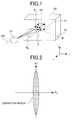
- the incident X-ray 100 is refracted by the object 101 and bent to follow a path 104.
- the x-axis component of the angle ⁇ formed by the incident X-ray 100 without bent and the path 104 that is, the deflection ⁇ x of the incident angle in a plane formed by the incident X-ray 100 and the diffracted X-ray 103 (x-z plane) becomes the deflection ⁇ b itself of the incident angle ⁇ b in expression (2). Since the Bragg's condition of diffraction in expression (2) is applied intact, therefore, intensity I of the diffracted X-ray sensitively changes with respect to ⁇ x .
- the y-axis component of the angle ⁇ formed by the rectilinear incident X-ray 100 and the path 104 that is, the deflection dp of the incident angle in a plane vertical to the plane formed by the incident X-ray and the diffracted X-ray (y-z plane) has the relationship with the deflection ⁇ b of ⁇ b that is shown in expression (3).
- ⁇ ⁇ b tan ⁇ b 1 ⁇ cos d ⁇
- Fig. 2 is an epitomic representation of the region in which X-ray diffraction occurs against ⁇ x and dp. This figure indicates that at narrower sections of the region, diffraction intensity changes more sensitively, namely, angular resolution becomes higher, with respect to an angular deflection. It can therefore be seen that there is almost no angular resolution with respect to dp and thus that there is the problem that the spatial differential of the phase shift in the y-axis direction cannot be obtained.
- Fig. 3B Spatial distribution images (diffraction images) of the diffraction intensity I which was calculated from numerical simulation results on the donut-shaped and mesh-shaped target objects shown in Fig. 3A are shown in Fig. 3B by way of example.
- Fig. 3B indicates that since the intensity of diffracted light does not almost change against dp, the contrast of the images is lost in the y-axis direction.
- the obtained image of its original shape shown in 3A exhibits high reproducibility since integral calculation can be started from the background.
- the mesh-shaped object since the absence of a background makes initial value setting impossible, a y-axial phase shift cannot be detected and the obtained image is not reproduced well.
- An object of the present invention is to provide means that makes it possible to detect a spatial differential of a phase shift caused by a target object, and to detect the phase shift, without observing the entire object.
- the present invention solves the above problems by using simultaneous diffraction as the X-ray diffraction using an analyzer crystal.
- the simultaneous diffraction here refers to a phenomenon in which an X-ray beam incident on the crystal simultaneously satisfies the diffraction conditions of plural crystal lattice planes and the beam is split into a plurality of beams by diffraction from each lattice plane.
- a Bragg-case and a Laue-case are present and both are further broadly divided into a coplanar type in which the planes formed by the incident X-ray beam and each diffracted X-ray beam are all parallel, and a nonplanar type in which the planes formed are not parallel.
- the present invention employs nonplanar simultaneous diffraction based on the Bragg-case and the Laue-case.
- unit vector "a" of "ko” is given by expression (5) with the deflection from the x-z plane as dp.
- incident angle ⁇ i with respect to the (n-1-1) plane is given by expression (7).
- ⁇ i sin ⁇ 1 ⁇ cos ⁇ a sin ⁇ b cos d ⁇ ⁇ sin ⁇ a sin d ⁇ Numerical expression 7
- d is a lattice plane spacing of the (n11) and (n-1-1) planes.
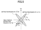
- Fig. 5 shows regions in which, as in Fig. 2, X-ray diffraction with respect to both the deflection ⁇ x and d ⁇ occurs on the above (n11) and (n-1-1) planes.
- Individual diffraction on each lattice plane is the same phenomenon as normal Bragg diffraction, and since the X-ray enters obliquely with respect to the lattice planes, the diffraction regions are merely inclined in comparison with the region of Fig. 2. This inclination, ⁇ s , is given by expression (9).
- ⁇ s tan ⁇ 1 cos ⁇ b / tan ⁇ a
- the "virtual diffraction intensity I i obtained in diffraction region C" is calculated as follows. That is, if the X-ray deflection ⁇ caused by refraction during passage through the object is present at point P in Fig. 5, since point P is included in the diffraction region A of the (n11) plane, the incident X-ray is diffracted on the (n11) plane. Conversely, point P is present outside the diffraction region B of the (n-1-1) plane, the incident X-ray is not diffracted on the (n-1-1) plane.
- I 1 is the diffraction intensity by the (n11) plane
- I 2 is the diffraction intensity by the (n-1-1) plane
- min(a, b) is a function that returns a value of "a” or "b", whichever is the smaller.
- ⁇ s is an angle given by expression (9).
- the magnitude of X-ray beam deflection ⁇ caused by the object is given by expression (14), and the direction ⁇ of the deflection can be calculated from expression (15).
- the phase shift can be calculated in three steps: (1) determining an initial phase value appropriately at a given point (say, an upper-left point) on the image, (2) calculating the amount of y-axial phase shift by integrating dp one line from that point, and (3) integrating each ⁇ x component from the line at which the amount of phase shift was calculated in step (2) above.
- Fig. 9 shows, in comparison with the numerical simulation results of Figs. 3 and 6, the calculation results on phase-contrast images (images with a phase shift as its contrast) that were obtained by the measurement using the above-described method of rotating the analyzer crystal 102. It can be seen from these results that the object shape that was initially assumed in Fig. 3A is restored very well.
- Sectional images of an object by nondestructive imaging which utilizes the high transmissibility of X-rays can be reconstructed in two steps: (1) with the object rotated with respect to an X-ray beam, acquiring phase-contrast images at various angles using the method described above, and (2) after completing all necessary measurements, reconstructing sectional images with the acquired phase-contrast images by calculation with a conventional X-ray CT algorithm.
- an image that uses both a spatial differential of an object-caused phase shift and the phase shift as its contrast can be detected without observing the entire object by using simultaneous diffraction as X-ray diffraction due to use of an analyzer crystal 102.
- a sectional image of the object with a phase shift as contrast can likewise be obtained by rotating the object.
- an image that uses, as its contrast, both an accurate spatial differential of an object-caused phase shift and the phase shift can be obtained at a small observation field size and under a simplified apparatus configuration.
- Fig. 10 is a block diagram showing an example of an X-ray imaging system according to the present invention. As shown in the figure, this system includes an X-ray source 1, a target object holder 2, an object holder supporting/positioning unit 3, an analyzer crystal 4, an analyzer crystal angle-adjusting unit 5, image detectors 6 and 7, and a processor 8.
- a target object 10 inside the object holder 2 that has been positioned by the object holder supporting/positioning unit 3 is irradiated with an X-ray beam 9 emitted from the X-ray source 1.
- An X-ray beam 11 that has been refracted by the object after transmitting therethrough enters the analyzer crystal 4, and only components that satisfy the Bragg's condition of diffraction are diffracted to form diffracted X-ray beams 12 and 13.
- the diffracted X-ray beams 12 and 13 have respective intensity levels detected by image detectors 6 and 7, and pixel-by-pixel intensity levels are saved as image data in the processor 8.
- the X-ray source 1 may be of a normal tube type or a rotary type, or may be synchrotron radiation. In the former case, however, since the X-ray beam emitted is divergent light, background noise of the image detectors 6, 7 and exposure of the object 10 by scattered X-rays can be reduced when a slit 15 with a variable aperture width is placed between the X-ray source and the object.
- the analyzer crystal 4 can be a crystal plate (or the like) formed by grinding a monolithic crystal and then polishing its surface into a non-strained state by mechano-chemical polishing or the like.
- the crystal has its dimensions determined considering an X-ray beam size extracted by the slit 15, wavelength of the X-ray beam, and the diffraction lattice plane sizes used.
- a horizontal size (width: W) of the X-ray beam 11 on the analyzer crystal 4 is given by expression (16), where a width of the X-ray beam 11 is taken as W b , the wavelength is taken as ⁇ , and the diffraction lattice planes used for simultaneous diffraction are taken as an (n11) plane and an (n-1-1) plane.
- W 2 d cos ⁇ a ⁇ W b
- the analyzer crystal can have a width equal to or greater than W.
- "d" is a lattice spacing of the (n11) plane
- ⁇ a is an angle formed by the (n11) plane and the crystal surface.
- the analyzer crystal 4 can have a vertical size equal to or greater than H b .
- Lattice planes that can be used for simultaneous diffraction exist in uncountable numbers. Lattice planes are therefore selected in the following procedure:
- a thicker object 10 requires a higher X-ray energy level for increased transmissibility.
- an angle of refraction ⁇ by the object is proportional to ⁇ , that is, inversely proportional to energy, so a higher energy level lessens the refractive angle ⁇ and thus reduces phase-shift detection sensitivity.
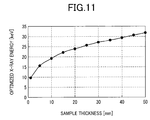
- step (2) above energy is determined using a graph that lists energy levels at which an S/N ratio of a typical object becomes a maximum for the thickness of the object.
- a graph of biological soft tissues is shown as an example in Fig. 11.
- lattice planes appropriated for the energy level that was calculated in step (2) can be selected from the list of optimum lattice planes for various X-ray energy levels, shown in Fig. 12.
- the kinds of constituent elements of the target object are preferably changed according to the X-ray energy level calculated in step (2). The changes are intended to utilize characteristic X-rays.
- a crystal holder 16 for holding the analyzer crystal 4 is formed to have an L-shape so as to be able to securely support the crystal from two sides.
- the X-ray source 1 is heavy, so the X-ray source is difficult to move for fine-adjustment.
- the analyzer crystal angle-adjusting unit 5 can use a normal swivel stage 17 for dp control, and a ⁇ -rotating stage 18. Rotation positioning accuracy of the rotating stage 18, however, needs to be narrowed down to a level low enough for the angular width that causes diffraction.
- a rotating stage (or the like) that uses a tangential bar whose accuracy is 100th of a second is suitable since the angular width that causes diffraction is usually several seconds of angle.
- X-ray sensing pickup tubes combinations of a phosphor, a lens system, and a CCD camera, or other equivalent units can be used as the image detectors 6 and 7.
- a measuring procedure is flowcharted in Fig. 13.
- an analyzer crystal 4 usable for the selected diffraction lattice planes is selected from a plurality of previously prepared analyzer crystals 4, and then the selected crystal 4 is secured to the analyzer crystal holder 16.
- the selected analyzer crystal 4 is rotated by operating the ⁇ -rotating stage 18 of the analyzer crystal angle-adjusting unit 5 to obtain a crystal angle at which the X-ray can be diffracted, that is, an angle ⁇ b that satisfies diffraction conditions.
- the adjusting time required can be substantially reduced since adjustments that use X-rays can be performed easily after the angle has been adjusted to a range of several seconds using an auto-collimator 19 as shown in Fig. 10.
- the adjusting time can also be reduced if high-speed rotational scanning is possible by using PIN diode detectors, scintillation counters, or other rapid-response X-ray detectors, instead of the image detectors 6 and 7, during the angle adjustment.
- dp axis rotation and ⁇ -axis rotation are repeated in an alternate fashion to conduct adjustments for an angle at which the diffracted X-ray beams 12 and 13 appear at the same time.
- background diffraction images are acquired using the image detectors 6 and 7, without the object 10 set up.
- the object 10 is set up in the object holder 2, then positioned using the object holder positioning unit 3, and measured.
- image data that has been acquired with the object 10 set up is arithmetically subtracted the background image data in the processor 8, and then the "virtual diffraction intensity I i obtained in diffraction region C" is calculated using expression (11).
- an image with I i as contrast namely, an image with a spatial differential of a phase shift as contrast, is obtained and then displayed at the display unit 14.
- simultaneous diffraction is asymmetrical diffraction different in incident angle and exit angle, and appears with the object distorted on the diffraction images.
- the diffracted beams 12 and 13 exit obliquely with respect to the analyzer crystal 4, and thus the unit for positioning the image detectors 6 and 7 is required to be sophisticatedly movement.
- This problem can be solved by, as shown in Fig. 14A, providing at a downstream position of the analyzer crystal a crystal plate 20 whose plane is parallel a face opposed to the analyzer crystal 4.
- the X-ray beams that enter the crystal plate 20 are, needless to say, the beams 12 and 13 diffracted by the analyzer crystal.
- the analyzer crystal 4 and the crystal plate 20 can be independently constructed in terms of principles, if both are formed into an integrated crystal block as shown in Fig. 14A, the positioning and angle-adjusting units and other adjusting units can have respective configurations simplified, as is the case with the integration of the analyzer crystal into a single block.
- Fig. 14B shows a case in which the analyzer crystal 4 and the crystal plate 20 are non-parallel to each other and inclined by an angle ⁇ .
- X-ray beams 21 and 22 are spread by the crystal plate 20 at the same time the beams are diffracted thereby, so the object 10 can be observed with high spatial resolution.
- ⁇ is an angle formed by the surfaces of the analyzer crystal 4 and the crystal plate 20. Since images are spread only in a ⁇ s direction and distorted, the distortion needs to be corrected by calculation in the processor when distortionless object images are required.
- the analyzer crystal 4 and the crystal plate 20 also need to be increased in size.
- the analyzer crystal 4 needs to have very large sizes of at least 21 cm in width and at least 5 cm in height.
- Laue-case simultaneous diffraction as shown in Fig. 15A may be used instead of Bragg-case diffraction.
- crystal plates 201, 202 can be essentially of the same size as that of the observation field.
- thickness "t" of the crystal plates 201, 202 is desirably as thin as possible to avoid X-ray absorption, it is appropriate for "t" to be about 1 mm, since crystal plates that are too thin lose their mechanical rigidity as well and distort the crystals themselves. Even with the thickness of about 1 mm, however, absorption becomes too significant at low energy levels below 15 keV.
- the crystal plate 201 may be supported using a housing 203, and only a thickness of a crystal plate 201 through which an actual X-ray is to penetrate may be controlled below 1 mm. The same also applies to the crystal plate 202.
- a procedure for obtaining phase-contrast images of the object 10 is flowcharted in Fig. 16. These images can be obtained by measuring diffraction image data at various angles of the analyzer crystal 4, then after storing measured image data in the processor 8 and completing all measurements, activating the processor to calculate ⁇ 1 and ⁇ 2 at which diffraction intensity is maximized on a pixel-by-pixel basis, and calculating an integral of ⁇ x by deriving ⁇ x and d ⁇ from ⁇ 1 and ⁇ 2 , subject to expressions (12) and (13).
- phase-contrast images of the object 10 can be obtained by: before setting up the object 10, similarly to the above, executing the procedure of Fig. 16 to measure phase-shift image data to be used as the background; then setting up the object 10; and conducting subtractions from the images obtained by adding acquired object images and phase shifts of the background.
- Sectional images of the object 10 can be obtained using the flowchart shown in Fig. 17, that is, by rotating the object 10 with respect to the X-ray beam 9, then obtaining phase-shift images at each rotational angle in accordance with the procedure of Fig. 16, and after conducting all measurements, activating the processor 8 to calculate sectional image data using a general X-ray CT algorithm. Any direction can be selected as a rotational axis of the object 10, provided that the axis is present in a plane vertical to the X-ray beam.
- the X-ray source 1, the analyzer crystal 4, and the detectors 6 and 7 may be rotated together around the object 10 after the object has been fixed.
- Figs. 18A and 18B show a second embodiment of a mammography system (breast cancer diagnosing system) constructed as an example of a diagnosing system which utilizes such features of the imaging method of the present invention as very high sensitivity to light elements, and high suitability for observing biological soft tissues mainly composed of light elements.
- Fig. 18A is a top view schematically showing the above diagnosing system
- Fig. 18B is a side view schematically showing the diagnosing system.
- the diagnosing system is required to have a system component capable of minimizing an X-ray exposure rate, an observation field wide enough for the system to acquire a image of a target object at a time, and stability (reproducibility) high enough for the system to obtain the same image from any number of measurements repeated.
- the second embodiment has an X-ray shield wall 23 for isolating an X-ray source 1 from a patient under examination, and an X-ray shield cover 24 for irradiating only a target object with X-rays.
- These added system components prevent X-ray irradiation of regions other than the patient's target regions to be X-ray irradiated.
- Both the X-ray shield wall 23 and the X-ray shield cover 24 have a small hole only at respective sections through which X-rays are passed.
- the system also has a beam-enlarging asymmetrical crystal plate 25 for shaping/enlarging an X-ray beam, and an angle feedback unit 26 for positioning an analyzer crystal 4 for an angle accuracy of 100th of a second.
- the system employs the integrated structure shown in Fig. 14A, the structure being formed by integrating the analyzer crystal 4 and crystal plate 20 of Fig. 14A.
- the integrated structure is supported by a crystal holder 16.
- the integrated structure may be used for such Laue-case diffraction as shown in Fig. 15A.
- Reference number 61 denotes a supporting section of the beam-enlarging asymmetrical crystal plate 25. This supporting section, although not shown, has a diffraction angle controller.
- the X-ray shield wall 23 is installed between the X-ray source 1 and the beam-enlarging asymmetrical crystal plate 25 in order to shield only unnecessary X-rays of all those emitted from the X-ray source 1.
- the X-ray shield wall 23 is a thick wall that contains lead and/or other substances, and this shield wall can shield 100% of X-ray intensity.
- the X-ray shield cover 24 is for totally covering the beam-enlarging asymmetrical crystal plate 25, the analyzer crystal 4, the crystal plate 20, and other major system components, and prevents the target object and the image detectors 6 and 7 from being irradiated with any X-rays scattered by each crystal.
- a lead-containing acrylic plate, a thinly-lead-coated iron plate, or the like is used as the shield cover 24.
- the section thereof that is constructed to place the object 10 inside a path of the X-ray beam has a concave portion as shown in Fig. 18A. Patient except for the portion of the object 10 that is to be irradiated with the beam is thus protected therefrom.
- Heat from a patient 27 under examination may cause undesirable events such as distortion of a lattice plane spacing between the beam-enlarging asymmetrical crystal plate 25 and the analyzer crystal 4. If the lattice plane spacing is likely to be disturbed for these reasons, the beam-enlarging asymmetrical crystal plate 25 and the analyzer crystal 4 are spaced at least 30 cm from each other to suppress the disturbance. Also, the floor vibration and/or other effects caused by a change of the patient 27 for another patient are suppressed by installing the beam-enlarging asymmetrical crystal plate 25, the analyzer crystal 4, and the crystal plate 20, on one vibration-insulating table 28.
- the vibration-insulating table 28 is also concave-shaped near the patient, preventing the patient from touching the table.
- Fig. 19 is a diagram explaining more specifically a structural example relating to holding and controlling the analyzer crystal 4 and the crystal plate 20.
- the analyzer crystal 4 and the crystal plate 20 may be constructed into an integrated crystal block form as shown in Fig. 14, a size of this crystal block, that is, an observation field is most likely to be limited in that case.
- the analyzer crystal 4 and the crystal plate 20 are even more spaced for an isolated structure, and respective diffraction plane angles of the analyzer crystal 4 and the crystal plate 20 are controlled to essentially the same extent as that of the integrated formation thereof.
- Fig. 19 assumes the above construction. That is to say, the analyzer crystal 4 and the crystal plate 20 are independently supported by the crystal holder 16 and a crystal holder 16', respectively, and independently placed on a table 70 and an upper table 40 of a second tilt stage 30, respectively. The additional intercrystal angle adjustment required by such separation of the analyzer crystal 4 and the crystal plate 20 is conducted using a second ⁇ -stage 29 and the second tilt stage 30.
- the second ⁇ -stage 29 uses a solid-state sleeve bearing capable of obtaining high mechanical rigidity, even for increased crystal sizes. That is, as shown, an upper table 31 of the second ⁇ -stage 29 is mounted on a lower table 32 via a solid-state sleeve member made of a specially processed synthetic resin. Also, the upper table is connected at its left end to the lower table by a pivot 35. In addition, an expandable unit that uses a piezoelectric element 34 is provided at a right end of the upper table.
- the expandable unit using the piezoelectric element 34 is fixed at one end to the upper table 31 and at the other end to the lower table 32.
- a control voltage source 33 is changed in output voltage and the piezoelectric element 34 is expanded/contracted, therefore, the upper table 31 is driven to rotate around the pivot 35, in a direction of the arrow shown at right of the second ⁇ -stage 29.
- An area of a section at which the upper table 31 and the lower table 32 are in contact with each other via the sleeve member is larger than for a normal stage using ball bearing, so that high mechanical rigidity is obtainable.
- the rotation of the upper table 31 with respect to the lower table 32 rotates the second tilt stage 30 supported on the upper table 31, thus causing the crystal plate 20 supported on the second tilt stage 30 to rotate with the crystal holder 16'.
- the respective diffraction plane angles of the analyzer crystal 4 and the crystal plate 20 can thus be rotated about the y-axis shown in Fig. 4.
- the second tilt stage 30 has an upper table 40 and a lower table 39 connected to each other at one end by a roll bearing 38, and has an expandable unit that uses a piezoelectric element 37, at an edge of the other end.
- the expandable unit using the piezoelectric element 37 is fixed at one end to the upper table 40 and at the other end to the lower table 39.
- a tilt stage 17 on which the analyzer crystal 4, the crystal plate 20, the second ⁇ -stage 29, and the second tilt stage 30 are mounted is of the same structure as that of a second ⁇ -tilt stage 30.
- the tilt stage 17 has upper and lower tables connected to each other at one end by a roll bearing 43, and has an expandable unit that uses a piezoelectric element 42, at an edge of the other end.
- a control voltage source 41 is changed in output voltage and the piezoelectric element 42 is expanded/contracted, the tilt stage 17 is driven to rotate around the roll bearing 43.
- a ⁇ -stage 18 with the tilt stage 17 thereon is of the same structure as that of the second ⁇ -stage 29.
- the ⁇ -stage 18 has upper and lower tables connected to each other at one end by a pivot 46, and has an expandable unit that uses a piezoelectric element 45, at an edge of the other end.
- a control voltage source 44 is changed in output voltage and the piezoelectric element 45 is expanded/contracted, the ⁇ -stage 18 is driven to rotate around pivot 46.
- rotational drifts of each stage need to be controlled below 100th of a second of angle.
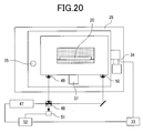
- Such an angle feedback unit as shown in Fig. 20 is therefore provided. Only a feedback unit of the second ⁇ -stage 29 is shown in Fig. 20.
- rotational drifts can also be suppressed by incorporating a similar feedback unit.
- This feedback unit is adapted to measure each crystal angle using a laser-based optical method, then after calculating a deviation ⁇ A with respect to a preset angle, use the control voltage source 33 to adjust according to ⁇ A, the voltage applied to the piezoelectric element 34, and control ⁇ A to zero.
- a laser beam emitted from a laser 47 is split into two beams by a half-mirror 48, then these beams are diffracted by table-mounted corner cubes 49 and 50, and the diffracted beams are coupled, and made to interfere with each other via the half-mirror 48. Intensity of the interference is monitored by a detector 51, and a signal from the laser is processed/calculated by a processor 52, whereby an angle is detected.
- the laser light may be diffracted on the crystal surface itself, not on the corner cubes.
- the thickness (breast) of the target object significantly varies from person to person. Therefore, thicknesses of individual target objects are measured beforehand, then as described in the first embodiment, optimum X-ray energy is determined using such a graph as in Fig. 11, and lattice planes to be used for simultaneous diffraction are further determined in accordance with Fig. 12.
- crystals that have Si (422) crystal surfaces are convenient since any combination, whether it be a combination of Si (220) and Si (202), Si (440) and Si (404), or Si (660) and Si (606), can be immediately used only by adjusting angle without replacing the analyzer crystal.
- measurements with X-rays are conducted using the flowchart of Fig. 13 to obtain images whose spatial differentials of phase shifts are to be taken as contrast, or using the flowchart of Fig. 16 to obtain images whose phase shifts are to be taken as contrast.
- the latter method increases a dose rate, so the former method may be used for a screening examination, and the latter method for a re-examination and a closer examination.
Landscapes
- Health & Medical Sciences (AREA)
- Life Sciences & Earth Sciences (AREA)
- Engineering & Computer Science (AREA)
- Medical Informatics (AREA)
- Pathology (AREA)
- General Health & Medical Sciences (AREA)
- Physics & Mathematics (AREA)
- Surgery (AREA)
- Veterinary Medicine (AREA)
- Nuclear Medicine, Radiotherapy & Molecular Imaging (AREA)
- Radiology & Medical Imaging (AREA)
- Biomedical Technology (AREA)
- Heart & Thoracic Surgery (AREA)
- Molecular Biology (AREA)
- High Energy & Nuclear Physics (AREA)
- Animal Behavior & Ethology (AREA)
- Biophysics (AREA)
- Public Health (AREA)
- Optics & Photonics (AREA)
- Chemical & Material Sciences (AREA)
- Dentistry (AREA)
- Oral & Maxillofacial Surgery (AREA)
- Crystallography & Structural Chemistry (AREA)
- Analytical Chemistry (AREA)
- Biochemistry (AREA)
- General Physics & Mathematics (AREA)
- Immunology (AREA)
- Analysing Materials By The Use Of Radiation (AREA)
- Apparatus For Radiation Diagnosis (AREA)
Applications Claiming Priority (1)
| Application Number | Priority Date | Filing Date | Title |
|---|---|---|---|
| JP2005140746A JP4676244B2 (ja) | 2005-05-13 | 2005-05-13 | X線撮像装置 |
Publications (2)
| Publication Number | Publication Date |
|---|---|
| EP1722216A2 true EP1722216A2 (fr) | 2006-11-15 |
| EP1722216A3 EP1722216A3 (fr) | 2010-05-19 |
Family
ID=36999800
Family Applications (1)
| Application Number | Title | Priority Date | Filing Date |
|---|---|---|---|
| EP06001756A Withdrawn EP1722216A3 (fr) | 2005-05-13 | 2006-01-27 | Système d'imagerie par rayons-X |
Country Status (4)
| Country | Link |
|---|---|
| US (1) | US7346145B2 (fr) |
| EP (1) | EP1722216A3 (fr) |
| JP (1) | JP4676244B2 (fr) |
| CN (1) | CN1860997B (fr) |
Cited By (1)
| Publication number | Priority date | Publication date | Assignee | Title |
|---|---|---|---|---|
| EP2009429A1 (fr) * | 2007-06-26 | 2008-12-31 | Hitachi Ltd. | Imagerie à contraste de phase utilisant la diffraction des rayons X en geometrie Laue avec crystaux analyseurs rotatives |
Families Citing this family (13)
| Publication number | Priority date | Publication date | Assignee | Title |
|---|---|---|---|---|
| JP5041750B2 (ja) | 2006-07-20 | 2012-10-03 | 株式会社日立製作所 | X線撮像装置及び撮像方法 |
| DE102008064633B4 (de) * | 2008-02-06 | 2017-05-04 | Fraunhofer-Gesellschaft zur Förderung der angewandten Forschung e.V. | Vorrichtung und Verfahren zum Erfassen eines Bildes |
| JP5256352B2 (ja) * | 2009-10-29 | 2013-08-07 | 株式会社日立製作所 | X線撮像装置及びx線撮像方法 |
| US8477904B2 (en) * | 2010-02-16 | 2013-07-02 | Panalytical B.V. | X-ray diffraction and computed tomography |
| US9861330B2 (en) * | 2010-10-19 | 2018-01-09 | Koninklijke Philips N.V. | Differential phase-contrast imaging |
| JP2014006247A (ja) * | 2012-05-28 | 2014-01-16 | Canon Inc | 被検体情報取得装置、被検体情報取得方法及びプログラム |
| CN104833684A (zh) * | 2015-05-15 | 2015-08-12 | 聂志虎 | 多功能混凝土结构透视仪 |
| KR102373431B1 (ko) * | 2016-05-16 | 2022-03-11 | 신토고교 가부시키가이샤 | 표면 처리 가공 방법 및 표면 처리 가공 장치 |
| KR101879169B1 (ko) * | 2016-11-22 | 2018-07-17 | 오주영 | 카메라 영상을 이용한 방사선 촬영 가이드 시스템 및 방법 |
| JP7078815B2 (ja) * | 2018-03-28 | 2022-06-01 | 秀和 三村 | X線撮影方法およびx線撮影装置 |
| JP6871629B2 (ja) * | 2018-06-29 | 2021-05-12 | 株式会社リガク | X線分析装置及びその光軸調整方法 |
| CN111982278B (zh) * | 2020-08-04 | 2021-07-13 | 中国科学院高能物理研究所 | 一种利用同步辐射偏振性探测束流位置的探测器及方法 |
| CN114088749B (zh) * | 2020-08-05 | 2024-04-19 | 中国石油化工股份有限公司 | 快速识别页岩中碎屑石英与生物成因石英的方法及装置 |
Citations (3)
| Publication number | Priority date | Publication date | Assignee | Title |
|---|---|---|---|---|
| EP0784202A2 (fr) | 1996-01-10 | 1997-07-16 | Hitachi, Ltd. | Appareil de tomographie à rayons X en contraste de phase |
| US5850425A (en) | 1993-08-16 | 1998-12-15 | Commonwealth Scientific And Industrial Research Organisation | X-ray optics, especially for phase contrast |
| US5930325A (en) | 1996-03-29 | 1999-07-27 | Hitachi, Ltd. | Phase-contrast x-ray imaging system |
Family Cites Families (20)
| Publication number | Priority date | Publication date | Assignee | Title |
|---|---|---|---|---|
| US3446961A (en) * | 1966-02-01 | 1969-05-27 | Research Corp | X-ray interferometer using three spaced parallel crystals |
| US5173928A (en) * | 1990-07-09 | 1992-12-22 | Hitachi, Ltd. | Tomograph using phase information of a signal beam having transmitted through a to-be-inspected object |
| JP3114247B2 (ja) | 1990-07-09 | 2000-12-04 | 株式会社日立製作所 | 位相型トモグラフィ装置 |
| US5259013A (en) * | 1991-12-17 | 1993-11-02 | The United States Of America As Represented By The Secretary Of Commerce | Hard x-ray magnification apparatus and method with submicrometer spatial resolution of images in more than one dimension |
| JP3548664B2 (ja) | 1996-03-29 | 2004-07-28 | 株式会社日立製作所 | 位相コントラストx線撮像装置 |
| US5864599A (en) * | 1996-04-26 | 1999-01-26 | Cowan Paul Lloyd | X-ray moire microscope |
| US5812629A (en) * | 1997-04-30 | 1998-09-22 | Clauser; John F. | Ultrahigh resolution interferometric x-ray imaging |
| JP3422289B2 (ja) * | 1999-06-14 | 2003-06-30 | 日本電気株式会社 | X線位相差撮影装置 |
| JP2001033406A (ja) * | 1999-07-16 | 2001-02-09 | Nec Corp | X線位相差撮像方法及びx線位相差撮像装置 |
| WO2001079823A2 (fr) * | 2000-04-17 | 2001-10-25 | Leroy Dean Chapman | Imagerie aux rayons x du cartilage articulaire, amelioree par diffraction |
| JP3689623B2 (ja) * | 2000-09-05 | 2005-08-31 | 株式会社日立製作所 | X線撮像装置 |
| US6870896B2 (en) * | 2000-12-28 | 2005-03-22 | Osmic, Inc. | Dark-field phase contrast imaging |
| JP2003010162A (ja) * | 2001-07-04 | 2003-01-14 | Nagata Seiki Co Ltd | 位相コントラストx線撮像装置 |
| JP4498663B2 (ja) * | 2001-07-11 | 2010-07-07 | 学校法人東京理科大学 | 透過型結晶分析体の厚さ設定方法 |
| AUPS299302A0 (en) * | 2002-06-17 | 2002-07-04 | Monash University | Methods and apparatus of sample analysis |
| WO2004058070A1 (fr) * | 2002-12-26 | 2004-07-15 | Atsushi Momose | Systeme d'imagerie a rayons x et procede d'imagerie associe |
| CN1282892C (zh) * | 2003-10-20 | 2006-11-01 | 南京大学 | 基于光学干涉和色散原理的偏振分波的方法和装置 |
| JP4704675B2 (ja) * | 2003-11-28 | 2011-06-15 | 株式会社日立製作所 | X線撮像装置及び撮像方法 |
| JP2005265840A (ja) * | 2004-02-17 | 2005-09-29 | Seiichi Hayashi | 分析装置 |
| US7076025B2 (en) * | 2004-05-19 | 2006-07-11 | Illinois Institute Of Technology | Method for detecting a mass density image of an object |
-
2005
- 2005-05-13 JP JP2005140746A patent/JP4676244B2/ja not_active Expired - Fee Related
-
2006
- 2006-01-27 US US11/340,526 patent/US7346145B2/en not_active Expired - Fee Related
- 2006-01-27 CN CN2006100022735A patent/CN1860997B/zh not_active Expired - Fee Related
- 2006-01-27 EP EP06001756A patent/EP1722216A3/fr not_active Withdrawn
Patent Citations (3)
| Publication number | Priority date | Publication date | Assignee | Title |
|---|---|---|---|---|
| US5850425A (en) | 1993-08-16 | 1998-12-15 | Commonwealth Scientific And Industrial Research Organisation | X-ray optics, especially for phase contrast |
| EP0784202A2 (fr) | 1996-01-10 | 1997-07-16 | Hitachi, Ltd. | Appareil de tomographie à rayons X en contraste de phase |
| US5930325A (en) | 1996-03-29 | 1999-07-27 | Hitachi, Ltd. | Phase-contrast x-ray imaging system |
Cited By (2)
| Publication number | Priority date | Publication date | Assignee | Title |
|---|---|---|---|---|
| EP2009429A1 (fr) * | 2007-06-26 | 2008-12-31 | Hitachi Ltd. | Imagerie à contraste de phase utilisant la diffraction des rayons X en geometrie Laue avec crystaux analyseurs rotatives |
| US7778389B2 (en) | 2007-06-26 | 2010-08-17 | Hitachi, Ltd. | X-ray imaging system and method |
Also Published As
| Publication number | Publication date |
|---|---|
| JP2006317305A (ja) | 2006-11-24 |
| JP4676244B2 (ja) | 2011-04-27 |
| CN1860997B (zh) | 2011-01-05 |
| US20060256918A1 (en) | 2006-11-16 |
| EP1722216A3 (fr) | 2010-05-19 |
| CN1860997A (zh) | 2006-11-15 |
| US7346145B2 (en) | 2008-03-18 |
Similar Documents
| Publication | Publication Date | Title |
|---|---|---|
| US7346145B2 (en) | X-ray imaging system | |
| Dilmanian et al. | Computed tomography of x-ray index of refraction using the diffraction enhanced imaging method | |
| US8588366B2 (en) | X-ray imaging apparatus and X-ray imaging method | |
| US7778389B2 (en) | X-ray imaging system and method | |
| EP2586373B1 (fr) | Interféromètre à rayons X | |
| KR100455232B1 (ko) | 위상콘트라스트 이미징 방법 및 장치,그리고 이를 이용하여 위상분포를 판정하는방법 | |
| EP2557437B1 (fr) | Capteur pour un faisceau | |
| JP5238787B2 (ja) | 放射線撮影装置及び放射線撮影システム | |
| US20130108020A1 (en) | X-ray apparatus and x-ray measuring method | |
| EP1062914A1 (fr) | Tomographie par rayons x a angle ultra-reduit | |
| JP5041750B2 (ja) | X線撮像装置及び撮像方法 | |
| JPH10248833A (ja) | 位相コントラストx線撮像装置 | |
| JP2007510456A (ja) | 干渉性散乱撮像 | |
| JP2001524011A (ja) | 組織分析装置 | |
| DiBianca et al. | A variable resolution x‐ray detector for computed tomography: I. Theoretical basis and experimental verification | |
| Maksimenko et al. | Dark-field imaging using an asymmetric Bragg case transmission analyser | |
| de La Rochefoucauld et al. | Single-shot, high sensitivity X-ray phase contrast imaging system based on a Hartmann mask | |
| WO2011052419A1 (fr) | Dispositif d'imagerie par rayons x et procédé d'imagerie par rayons x | |
| US9042517B2 (en) | X-ray imaging apparatus | |
| JPH0783744B2 (ja) | X線断層撮影装置 | |
| JP4561312B2 (ja) | X線画像再構成装置 | |
| Fiedler et al. | Evaluation of two phase contrast techniques: diffraction-enhanced imaging and propagation | |
| JPH05340894A (ja) | K吸収端差分法を用いたx線画像撮影装置並びにx線ct装置 | |
| Momose et al. | Recent observations with phase-contrast X-ray computed tomography | |
| JPH0692884B2 (ja) | X線断層撮影装置 |
Legal Events
| Date | Code | Title | Description |
|---|---|---|---|
| PUAI | Public reference made under article 153(3) epc to a published international application that has entered the european phase |
Free format text: ORIGINAL CODE: 0009012 |
|
| AK | Designated contracting states |
Kind code of ref document: A2 Designated state(s): AT BE BG CH CY CZ DE DK EE ES FI FR GB GR HU IE IS IT LI LT LU LV MC NL PL PT RO SE SI SK TR |
|
| AX | Request for extension of the european patent |
Extension state: AL BA HR MK YU |
|
| PUAL | Search report despatched |
Free format text: ORIGINAL CODE: 0009013 |
|
| AK | Designated contracting states |
Kind code of ref document: A3 Designated state(s): AT BE BG CH CY CZ DE DK EE ES FI FR GB GR HU IE IS IT LI LT LU LV MC NL PL PT RO SE SI SK TR |
|
| AX | Request for extension of the european patent |
Extension state: AL BA HR MK YU |
|
| RIC1 | Information provided on ipc code assigned before grant |
Ipc: G21K 1/06 20060101ALI20100409BHEP Ipc: G01N 23/207 20060101AFI20060926BHEP |
|
| 17P | Request for examination filed |
Effective date: 20101119 |
|
| AKX | Designation fees paid |
Designated state(s): DE FR GB |
|
| 17Q | First examination report despatched |
Effective date: 20110316 |
|
| STAA | Information on the status of an ep patent application or granted ep patent |
Free format text: STATUS: THE APPLICATION IS DEEMED TO BE WITHDRAWN |
|
| 18D | Application deemed to be withdrawn |
Effective date: 20120727 |