EP1719844A1 - Ablaufventil für einen Spülkasten - Google Patents
Ablaufventil für einen Spülkasten Download PDFInfo
- Publication number
- EP1719844A1 EP1719844A1 EP05405339A EP05405339A EP1719844A1 EP 1719844 A1 EP1719844 A1 EP 1719844A1 EP 05405339 A EP05405339 A EP 05405339A EP 05405339 A EP05405339 A EP 05405339A EP 1719844 A1 EP1719844 A1 EP 1719844A1
- Authority
- EP
- European Patent Office
- Prior art keywords
- valve
- auxiliary
- valve body
- auxiliary valve
- opening
- Prior art date
- Legal status (The legal status is an assumption and is not a legal conclusion. Google has not performed a legal analysis and makes no representation as to the accuracy of the status listed.)
- Granted
Links
Images



Classifications
-
- E—FIXED CONSTRUCTIONS
- E03—WATER SUPPLY; SEWERAGE
- E03D—WATER-CLOSETS OR URINALS WITH FLUSHING DEVICES; FLUSHING VALVES THEREFOR
- E03D1/00—Water flushing devices with cisterns ; Setting up a range of flushing devices or water-closets; Combinations of several flushing devices
- E03D1/02—High-level flushing systems
- E03D1/14—Cisterns discharging variable quantities of water also cisterns with bell siphons in combination with flushing valves
- E03D1/142—Cisterns discharging variable quantities of water also cisterns with bell siphons in combination with flushing valves in cisterns with flushing valves
- E03D1/144—Cisterns discharging variable quantities of water also cisterns with bell siphons in combination with flushing valves in cisterns with flushing valves having a single flush outlet and an additional float for delaying the valve closure
-
- E—FIXED CONSTRUCTIONS
- E03—WATER SUPPLY; SEWERAGE
- E03D—WATER-CLOSETS OR URINALS WITH FLUSHING DEVICES; FLUSHING VALVES THEREFOR
- E03D1/00—Water flushing devices with cisterns ; Setting up a range of flushing devices or water-closets; Combinations of several flushing devices
- E03D1/02—High-level flushing systems
- E03D1/14—Cisterns discharging variable quantities of water also cisterns with bell siphons in combination with flushing valves
- E03D2001/147—Cisterns discharging variable quantities of water also cisterns with bell siphons in combination with flushing valves having provisions for active interruption of flushing
Definitions
- the invention relates to a drain valve for a cistern, comprising a main valve having a main valve body in a valve housing, which forms a piston, via which a discharge chamber is arranged, with a first auxiliary valve, with which the discharge chamber for Spülausaims is at least partially emptied and with a second auxiliary valve with which the discharge chamber for a rinse interruption is floatable.
- Drain valves for cisterns have long been known.
- drainage valves which enable partial flushing with, for example, three liters of rinsing water have proved to be useful.
- either a full flush or a partial flush can be selected.
- two buttons are provided for flushing. Pressing one key causes a partial flush and a full flush when the other key is pressed.
- a drain valve that allows such a two-stage flush is out of the EP 0 722 020 B became known.
- this drain valve the valve body is raised to initiate the flushing process.
- a float controls a lever which prematurely releases the valve body so that it falls onto the valve seat prior to emptying the flushing cistern.
- this drain valve has proven itself many times.
- the drain valve has the advantage that it can be built very compact. The actuating force as well as the actuating travel when opening and closing the valve but are relatively large.
- the drain valve has a main valve body, which can be lifted from its seat by actuating an auxiliary valve by means of an actuating device due to a negative water balance occurring in a relief chamber.
- a negative pressure which raises the main valve body in the manner of a piston.
- an auxiliary auxiliary valve is provided, which is at least to open briefly to flood the discharge chamber. When the discharge chamber floods, a positive water balance is formed, causing the main valve body to prematurely close.
- the auxiliary auxiliary valve is assigned to a partial emptying a floating body.
- the auxiliary valve has an auxiliary valve body, which is to move down to trigger the flushing. This is a spring tensioned.
- This drain valve consists of comparatively many individual parts and requires a comparatively large volume of construction, which is particularly disadvantageous in concealed cisterns.
- EP 1 270 831 is a drain valve has become known, which also has an auxiliary valve and allows a release with a comparatively small actuation force. Both the opening and closing of the auxiliary valve is float controlled. The closing of the valve is delayed, which is disadvantageous.
- the invention has for its object to provide a drain valve of the type mentioned, which allows a partial flush and can be opened and closed with the smallest possible operating force and small actuation travel and can still be built compact and with relatively small volume.
- the drain valve should also be reliable.
- the object is achieved in a generic drain valve in that the first and the second auxiliary valve have a common auxiliary valve body which releases the valve opening of the first auxiliary valve and the valve opening of the second auxiliary valve closes at a Spülauslect.
- auxiliary auxiliary valve with a corresponding second auxiliary valve body is not required.
- the auxiliary valve with which the discharge chamber is at least partially emptied and the second auxiliary valve, with which the discharge chamber is flooded, are operated with the same auxiliary valve body.
- the opening of the valve opening of the first auxiliary valve and the closing of the valve opening of the second auxiliary valve can be carried out with a comparatively short stroke movement of the auxiliary valve body and thus with a correspondingly short actuating travel. This allows a much simpler and more compact construction of the drain valve. Due to the small actuating force and the small actuating travel, the drain valve is particularly suitable for a motorized operation.
- a particularly compact design results when, according to a development of the invention, the valve opening of the first auxiliary valve and the valve opening of the second auxiliary valve are arranged on the main valve body. This also allows the number of items to be significantly reduced.
- the auxiliary valve body is vertically movable between the valve opening of the first auxiliary valve and the valve opening of the second auxiliary valve.
- the two auxiliary valve openings are arranged directly above one another.
- the first auxiliary valve is opened by lifting the main valve body and closed with the same stroke, the valve opening of the second main valve body.
- the main valve body is held in its basic position by a first pawl down and that this pawl is pivoted at a Spülauslect so that it releases the main valve body.
- a second pawl is arranged on the auxiliary valve body, with which the auxiliary valve body is connected to the main valve body. This allows a particularly reliable opening of the valve opening of the first auxiliary valve.
- the second latch cooperates with a float, which releases the auxiliary valve body upon reaching a predetermined Spülwassemiveaus.
- valve opening of the first auxiliary valve and the valve opening of the second auxiliary valve are arranged on the main valve body.
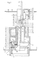
- FIG. 1 shows sections of a cistern 1, which may be formed as usual and having an actuating device, not shown here.
- the cistern 1 has at a bottom 11 a conventional outlet nozzle 12, in which a drain valve 10 is inserted.
- rinse water 66 is stored in the cistern 1 according to Figure 2 .
- the volume of the rinse water 66 is, for example, with a full cistern 1, six or nine liters.
- FIG. 2 shows the water surface 46 when the cistern 1 is filled.
- the drain valve 10 is used to empty the cistern 1, where it is opened, for example, to actuate a button, not shown here and rinse water flows through the outlet nozzle 12 in a toilet bowl, not shown here.
- the flushing takes place as mentioned, for example by pressing a button.
- a non-contact motor control is conceivable.
- the drain valve 10 has a valve housing 2, which has a valve opening 5. Over this valve opening 5 a plurality of side openings 15 are arranged in the valve housing 2, through which rinse water 66 can flow with open valve opening 5 in the outlet pipe 12 and thus in the toilet bowl.
- the valve opening 5 forms a main valve body 3 with a main valve V.
- the main valve body 3 has a valve plate 14 which rests on a valve seat 13 in FIG.
- the main valve V is closed in Figures 1 to 3.
- the valve body 3 has at its periphery a piston ring 16 which bears against an inner side 17 of a discharge chamber 4 in a vertically displaceable sealing manner.
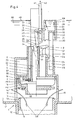
- the main valve body 3 seals with the sealing ring 16 the discharge chamber 4 down from. It forms a piston which is vertically movable between the lower position shown in FIG. 1 and an upper position shown in FIG. 4 with the stroke H3 shown in FIG.
- an auxiliary valve body 7 is mounted, which rests in Figure 1 on a valve seat 18 of a first auxiliary valve HV.
- a second valve seat 21 of a second auxiliary valve HV2 is arranged above this valve seat 18.
- This second valve seat 21 is formed by a pipe 67, which is integrally formed on the main valve body 3 by webs not shown here and has an upper edge 34.
- the tube 67 is open at an upper edge 34 and has a channel 6, which forms the valve opening of the second auxiliary valve HV2 at a lower end.
- the auxiliary valve body 3 is thus the common valve body for the first auxiliary valve HV1 and the second auxiliary valve HV2.
- the auxiliary valve body 7 has a valve disk 19 which rests on a valve seat 18 when the auxiliary valve HV1 is closed.
- the first auxiliary valve HV1 is closed and the second auxiliary valve HV2 is opened.
- the auxiliary valve body 7 is movable between the lower position shown in Figure 1 and the upper position shown in Figure 3 with a comparatively short stroke. This stroke is much shorter than the stroke H3 of the main valve body 3.
- the force required to lift the auxiliary valve body 7 is comparatively small.
- the second auxiliary valve HV2 is closed, but the first auxiliary valve HV1 is opened.
- the main valve body 3 has on an upper side 44 at least one control opening 20 which is open towards the relief chamber 4 and which connects the relief chamber 4 to an opening 68 of the first auxiliary valve HV1 when the first auxiliary valve HV1 is open.
- This opening 68 leads into the main valve opening 5.
- water present in the relief chamber 4 can flow out through the control opening 20 into the opening 68 and thus into the outlet connection 12.
- the pipe 67 of the main valve body 3 projects beyond the valve housing 2 when the main valve V is closed, as FIG. 1 shows.
- This tube 67 of the auxiliary valve body 7 is mounted.
- This auxiliary valve body 7 also projects beyond an upper end Valve housing 2 and has an overflow channel 22.
- the auxiliary valve body 7 forms in this case an overflow pipe, which determines the maximum filling of the cistern 1.
- the overflow channel 22 can also be arranged in a manner known per se outside the drainage valve 10.
- the auxiliary valve body 7 is thus not necessarily an overflow pipe.
- a float 69 is mounted, which forms an air chamber 26 and a water chamber 27 in a housing 25. These two chambers 26 and 27 are separated from each other by a bottom wall 32.
- the air in the air chamber 26 causes a buoyancy force according to arrow 28 and the water in the water chamber 27 at a partial emptying of the cistern ( Figure 5) a weight according to arrow 29.
- a rod 23 is fixed, the down in a Chamber 70 of the valve housing 2 protrudes.
- a stop cam 24 is formed, which allows a maximum stroke H1.
- FIG. 1 shows the float 69 in the lower position. Starting from this position, the float 69 can be lifted with the stroke H 1 by the buoyancy force of the air chamber 26.
- a cam 30 is mounted, with which the float 69 according to Figure 1 with empty or partially empty cistern 1 on a two-armed first pawl 8 loads.
- the pawl 8 is pivotally connected to the valve housing part 2 a with the valve housing 2 and surrounds the tube 67 in a semicircle.
- two cams 33 are mounted, which cooperate with the main valve body 3.
- the main valve body 3 has on its outer side two opposite vertically extending ribs 71 and 71 '(FIG. 6), which have an upper edge 72 and 72', respectively, against which a cam 33 according to FIG.
- the main valve body 3 In the position of the first pawl 8 shown in Figure 1, the main valve body 3 is locked in the closed position shown by the two cams 33. The main valve body 3 can thus not be raised. The illustrated position of the first pawl 8 is held in this position by the weight of the float 69. If the flushing cistern 1 according to FIG. 2 is filled with flushing water 66, the float 69 is shown in FIG raised to the highest position and thus the latch 8 relieved of the weight of the float 69. When emptying the cistern 1, the float 69 drops down again and loads with the cam 30 on the first pawl eighth
- a second also two-armed in the directions of the double arrow 65 pivotable pawl 9 is mounted, which surrounds the auxiliary valve body 7 in a semicircular shape and is connected thereto via a rotary joint 38.
- a respective driver 40 or 62 is arranged, on which a pull rod 41 or 60 (FIG. 6) engages.
- the drivers 40 and 62 each form a pin which engages in a slot 42 of the tie rod 41 and 60, respectively.
- the drawbar 41 and 60 can be raised with an actuating device, not shown here, for example with an actuating lever in the direction of arrow 43 and 63, respectively.
- a shoulder 36 is arranged, which rests with raised auxiliary valve body 7 at the edge 72 and 72 'of the rib 71 and 71' instead of the cam 33, as Figure 3 shows.
- the pull rod 41 and 60 it exerts on the second pawl 9 a torque, which acts with respect to the rotary joint 38 in Figure 1 in the counterclockwise direction.
- the first pawl 8 is rotated counterclockwise about the pivot 37 during lifting of the auxiliary valve body 7 and thus the two cams 33 are pushed away from the edge 72.
- the auxiliary valve body 7 is raised so that the main valve body 3 is locked to the auxiliary valve body 7.
- a further chamber 73 is arranged, which has according to Figure 7, an opening 75 which is closable with a slide 76.
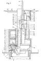
- a float 50 is arranged according to Figures 6 and 7, which is mounted pivotably about a pivot 53 on the valve housing 2.
- the float 50 is a so-called Kippschwimmer and has a lower air chamber 55 and an upper water chamber 58.
- the chambers 55 and 58 are separated by a bottom wall 57 from each other.
- the chamber 73 is filled with filled cistern according to Figure 2 with water.
- the air in the air chamber 55 causes a buoyant force according to arrow 56 and the water in the water chamber 58 at empty chamber 73 a weight according to the Arrow 59.
- a forwardly projecting nose 51 and an upwardly projecting stop cam 52 are arranged at the float 50.
- the stop cam 52 cooperates with the second pull rod 60.
- This pull rod 60 is provided for a full flush and can be raised in the direction of arrow 63.
- the second pull rod 60 has a slot 61 into which the catch 62 of the second pawl 9 engages. If the pull rod 60 is raised in the direction of the arrow 63, the pull rod 60 engages the driver 62 and thus pulls the main valve body 7 upwards.
- the pawl 8 rests simultaneously on the rib 71 and on the second opposing rib 71 '.
- the rib 71 ' also has an upper edge 72' on which the pawl 8 rests.
- the first pawl 8 and the second pawl 9 thus extend arcuately around the auxiliary valve body 7. In the figure 1, one side and in the figure 6, the other side is visible.
- the tongue 74 formed on the lower end of the second pull rod 60 is raised at the same time. In the basic position, this tongue 74 abuts the stop cam 52 according to FIG. 6 and thus prevents the float 50 from tilting about the pivot joint 53.
- the tongue 74 is raised above the stop cam 52 according to FIG. 7 and thus the float becomes 50 free and can pivot about the pivot 53 in a clockwise direction due to said torque.
- the nose 51 engages with a recess 64 of the rib 71 '. This causes a locking of the raised main valve body 3.
- the float 50 remains in this position as long as there is water in the chamber 73 and thus said torque is applied.
- the outflow of the water from the chamber 73 can be regulated with the slide 76 shown in FIG.
- This slider 76 is located in front of the opening 75 and can be moved in the directions of the double arrow 77. If the slider 76 is in the position shown in Figure 7, the opening 75 is closed. If the level of the rinse water 66 drops below the level of the opening 75, the water in the chamber 73 remains until the cistern 2 is substantially emptied. With the slide 76 raised, however, the chamber 73 empties relatively quickly, so that the chamber 73 is emptied before the cistern 1 is emptied. If the chamber 73 is emptied, said torque is no longer present and the float 50 tilts due to its weight immediately in the position shown in Figure 6.
- the main valve body 3 is thereby released and falls due to its own weight immediately on the valve seat 13, whereby the main valve V is closed.
- the auxiliary valve body 7 is unlocked prematurely and also falls due to its weight down and thus closes the first auxiliary valve HV1.
- the full amount can be set to six liters or nine liters. This is a default setting, which is usually not changed after the installation of the cistern 1.
- the cistern 1 is thus installed for a full flush with, for example, nine liters or for a full flush with six liters.
- the cistern 1 Before triggering a flushing the cistern 1 is filled with rinse water 66 according to FIG. Due to the buoyancy of the water, the float 69 is raised. The main valve body 3 is loaded in the closed position by the water 66. The discharge chamber 4 is also filled with water, which also rests on the main valve body 3.
- the pull rod 41 is raised in the direction of arrow 43.
- the comparatively small force for lifting the drawbar 41 can be done by hand or with a motor, not shown.
- the auxiliary valve body 7 is raised and, finally, in the raised position according to FIG. 3, the first pawl 8 is pivoted by a pivoting movement of the second pawl 9.
- the auxiliary valve body 7 is thus locked with the main valve body 3 and at the same time the locking of the main valve body 3 is lifted to the valve housing 2.
- the first auxiliary valve HV1 is opened and immediately thereafter the second auxiliary valve HV2 is closed with the same stroke.
- the auxiliary valve body 7 When lifting the main valve body 3, the auxiliary valve body 7 is at the same time, since it is locked as mentioned with the main valve body 3 by the second pawl 9. Since the rinse water 66 flows out of the cistern 1, the water surface 46 correspondingly decreases. If this water surface 46 reaches the float 69, the buoyancy of the float 69 subsequently decreases and the latter sinks accordingly. Finally, the cam 31 presses on the second pawl 9 and pivots it clockwise into the position shown in Figure 5. The cam 30 is now against the first pawl 8 and presses it against the ribs 71 and 71 '. The auxiliary valve body 7 is now unlocked and falls immediately due to its own weight on the valve seat 18. As a result, the first auxiliary valve HV1 is closed.
- the second pull rod 60 is raised in the direction of arrow 63 according to FIG.
- the purge is thus triggered as explained above, since in this case the main valve body 7 is raised and thus the first auxiliary valve HV1 is opened and the second auxiliary valve HV2 is closed.
- the float 50 is unlocked and this now tilts in Figure 6 clockwise about the axis of the pivot joint 53. If the main valve body 3 is raised by the stroke H2 (Fig. 6), the float 50 tilts further in the same direction and the nose 51 finally engages in the recess 64, as shown in Figure 7.
- the main valve body 3 is now locked to the valve housing 2.
- the swimmer 69 which sinks after the rinsing release, closes the auxiliary valve HV1 as in the case of a partial rinse, but remains ineffective and can not interrupt the rinsing. If the slider 76 is raised and thus the opening 75 free, the float 50 is pivoted as explained above before a complete emptying of the cistern 1 back into the position shown in Figure 6 and lifted the lock of the main valve body 3 and thus interrupted the flushing. In this case, a full flush is also carried out, but only with six instead of, for example, nine liters of rinse water 66th
Landscapes
- Health & Medical Sciences (AREA)
- Life Sciences & Earth Sciences (AREA)
- Engineering & Computer Science (AREA)
- Hydrology & Water Resources (AREA)
- Public Health (AREA)
- Water Supply & Treatment (AREA)
- Self-Closing Valves And Venting Or Aerating Valves (AREA)
- Float Valves (AREA)
- Sanitary Device For Flush Toilet (AREA)
Abstract
Description
- Die Erfindung betrifft ein Ablaufventil für einen Spülkasten, mit einem Hauptventil, das in einem Ventilgehäuse einen Hauptventilkörper aufweist, der einen Kolben bildet, über dem eine Entlastungskammer angeordnet ist, mit einem ersten Hilfsventil, mit dem die Entlastungskammer zur Spülauslösung wenigstens teilweise entleerbar ist und mit einem zweiten Hilfsventil, mit dem die Entlastungskammer für eine Spülunterbrechung flutbar ist.
- Ablaufventile für Spülkästen sind seit langem bekannt. Bewährt haben sich insbesondere Ablaufventile, welche eine Teilspülung mit beispielsweise drei Litern Spülwasser ermöglichen. Bei einem solchen Spülkasten kann wahlweise eine Vollspülung oder eine Teilspülung gewählt werden. In der Regel sind hierzu zwei Tasten für die Spülauslösung vorgesehen. Beim Drücken der einen Taste wird eine Teilspülung und beim Drücken der anderen Taste eine Vollspülung ausgelöst.
- Ein Ablaufventil, das eine solche Zweistufen-Spülung ermöglicht, ist aus der
EP 0 722 020 B bekannt geworden. Bei diesem Ablaufventil wird zur Spülauslösung der Ventilkörper angehoben. Bei einer Teilspülung steuert ein Schwimmer einen Hebel, welcher den Ventilkörper vorzeitig freigibt, so dass dieser vor der Entleerung des Spülkastens auf den Ventilsitz fällt. In der Praxis hat sich dieses Ablaufventil vielfach bewährt. Das Ablaufventil hat den Vorteil, dass es sehr kompakt gebaut werden kann. Die Betätigungskraft als auch der Betätigungsweg beim Öffnen und Schliessen des Ventils sind aber vergleichsweise gross. - Durch die
DE 92 15 972 U ist ein gattungsgemässes Ablaufventil bekannt geworden, bei dem die Spülauslösung mit einer kleineren Betätigungskraft möglich sein soll. Das Ablaufventil weist einen Hauptventilkörper auf, der durch Betätigen eines Hilfsventils mittels einer Betätigungseinrichtung aufgrund einer sich in einer Entlastungskammer einstellenden negativen Wasserbilanz von seinem Sitz abhebbar ist. Beim Entleeren der Entlastungskammer bildet sich in dieser ein Unterdruck, welcher den Hauptventilkörper in der Art eines Kolbens anhebt. Zur wahlweisen Teilentleerung ist ein Zusatz-Hilfsventil vorgesehen, das zum Fluten der Entlastungskammer zumindest kurzzeitig zu öffnen ist. Beim Fluten der Entlastungskammer bildet sich eine positive Wasserbilanz, wodurch der Hauptventilkörper vorzeitig schliesst. Dem Zusatz-Hilfsventil ist zur Teilentleerung ein Schwimmkörper zugeordnet. Das Hilfsventil besitzt einen Hilfsventilkörper, der zur Auslösung der Spülung nach unten zu bewegen ist. Hierbei wird eine Feder gespannt. Dieses Ablaufventil besteht aus vergleichsweise vielen Einzelteilen und erfordert ein vergleichsweise grosses Bauvolumen, was insbesondere bei Unterputzspülkästen nachteilig ist. - Durch die
EP 1 270 831 ist ein Ablaufventil bekannt geworden, das ebenfalls ein Hilfsventil aufweist und eine Auslösung mit einer vergleichsweise kleinen Betätigungskraft ermöglicht. Sowohl das Öffnen als auch das Schliessen des Hilfsventils ist schwimmergesteuert. Das Schliessen des Ventils erfolgt verzögert, was nachteilig ist. - Der Erfindung liegt die Aufgabe zugrunde, ein Ablaufventil der genannten Art zu schaffen, das eine Teilspülung ermöglicht und mit möglichst kleiner Betätigungskraft und kleinem Betätigungsweg geöffnet und geschlossen werden kann und das dennoch kompakt und mit vergleichsweise kleinem Volumen gebaut werden kann. Das Ablaufventil soll zudem funktionssicher sein.
- Die Aufgabe ist bei einem gattungsgemässen Ablaufventil dadurch gelöst, dass das erste und das zweite Hilfsventil einen gemeinsamen Hilfsventilkörper aufweisen, der bei einer Spülauslösung die Ventilöffnung des ersten Hilfsventils freigibt und die Ventilöffnung des zweiten Hilfsventils schliesst.
- Beim erfindungsgemässen Ablaufventil ist ein separates Zusatz-Hilfsventil mit einem entsprechenden zweiten Hilfsventilkörper nicht erforderlich. Das Hilfsventil, mit dem die Entlastungskammer wenigstens teilweise entleert wird und das zweite Hilfsventil, mit dem die Entlastungskammer geflutet wird, werden mit demselben Hilfsventilkörper bedient. Mit der gleichen Bewegung des Hilfsventilkörpers, mit dem die Ventilöffnung des ersten Hilfsventils freigegeben wird, wird auch die Ventilöffnung des zweiten Hilfsventils geschlossen. Das Öffnen der Ventilöffnung des ersten Hilfsventils und das Schliessen der Ventilöffnung des zweiten Hilfsventils kann mit einer vergleichsweise kurzen Hubbewegung des Hilfsventilkörpers und damit mit einem entsprechend kurzen Betätigungsweg erfolgen. Dies ermöglicht einen wesentlich einfacheren und kompakteren Aufbau des Ablaufventils. Aufgrund der kleinen Betätigungskraft und des kleinen Betätigungsweges eignet sich das Ablaufventil besonders für eine motorische Betätigung.
- Ein besonders kompakter Aufbau ergibt sich dann, wenn gemäss einer Weiterbildung der Erfindung die Ventilöffnung des ersten Hilfsventils und die Ventilöffnung des zweiten Hilfsventils am Hauptventilkörper angeordnet sind. Damit kann zudem die Anzahl der Einzelteile wesentlich verkleinert werden.
- Ein noch einfacherer Aufbau ergibt sich dann, wenn gemäss einer Weiterbildung der Erfindung der Hilfsventilkörper zwischen der Ventilöffnung des ersten Hilfsventils und der Ventilöffnung des zweiten Hilfsventils vertikal bewegbar ist. Vorzugsweise sind die beiden Hilfsventilöffnungen unmittelbar übereinander angeordnet. Durch eine vergleichsweise kleine vertikale Bewegung des Hauptventilkörpers kann das erste Hilfsventil geöffnet und das zweite Hilfsventil geschlossen werden. Dadurch ist ein besonders kurzer Betätigungsweg möglich.
- Vorzugsweise wird das erste Hilfsventil durch Anheben des Hauptventilkörpers geöffnet und mit dem gleichen Hub die Ventilöffnung des zweiten Hauptventilkörpers geschlossen.
- Nach einer Weiterbildung der Erfindung ist vorgesehen, dass der Hauptventilkörper in seiner Grundstellung von einer ersten Klinke nach unten gehalten ist und dass diese Klinke bei einer Spülauslösung so verschwenkt wird, dass sie den Hauptventilkörper freigibt.
- Nach einer Weiterbildung der Erfindung ist vorgesehen, dass am Hilfsventilkörper eine zweite Klinke angeordnet ist, mit welcher der Hilfsventilkörper mit dem Hauptventilkörper verbunden wird. Dies ermöglicht ein besonders funktionssicheres Öffnen der Ventilöffnung des ersten Hilfsventils.
- Nach einer Weiterbildung der Erfindung ist zur Auslösung der Teilspülung vorgesehen, dass die zweite Klinke mit einem Schwimmer zusammenarbeitet, welcher den Hilfsventilkörper beim Erreichen eines vorbestimmten Spülwassemiveaus freigibt.
- Eine besonders kostengünstige Herstellung und ein kompakter Aufbau ergibt sich dann, wenn gemäss einer Weiterbildung der Erfindung die Ventilöffnung des ersten Hilfsventils und die Ventilöffnung des zweiten Hilfsventils am Hauptventilkörper angeordnet sind.
- Weitere vorteilhafte Merkmale ergeben sich aus den abhängigen Patentansprüchen, der nachfolgenden Beschreibung sowie der Zeichnung.
- Ein Ausführungsbeispiel der Erfindung wird nachfolgend anhand der Zeichnung näher erläutert. Es zeigen:
- Figur 1
- schematisch ein Schnitt durch ein erfindungsgemässes Ablaufventil in einem hier lediglich teilweise gezeigten Spülkasten, wobei einzelne Teile aus zeichnerischen Gründen weggelassen sind.
- Figur 2
- eine Ansicht gemäss Figur 1, wobei der Spülkasten mit Wasser gefüllt ist,
- Figur 3
- ein Schnitt durch das Ablaufventil unmittelbar nach dem Öffnen des ersten Hilfsventils und dem Schliessen des zweiten Hilfsventils,
- Figur 4
- ein Schnitt durch das Ablaufventil bei geöffnetem Hauptventil,
- Figur 5
- ein Schnitt durch das Ablaufventil unmittelbar vor einer Spülunterbrechung nach einer Teilspülung,
- Figur 6
- ein weiterer Schnitt durch das Ablaufventil zur Erläuterung einer Vollspülung und
- Figur 7
- ein Schnitt gemäss Figur 6, wobei das Hauptventil geöffnet und eine volle Spülung ausgelöst ist.
- Die Figur 1 zeigt abschnittsweise einen Spülkasten 1, der wie üblich ausgebildet sein kann und eine hier nicht gezeigte Betätigungsvorrichtung aufweist. Der Spülkasten 1 weist an einem Boden 11 einen üblichen Ablaufstutzen 12 auf, in den ein Ablaufventil 10 eingesetzt ist. Im Spülkasten 1 ist gemäss Figur 2 Spülwasser 66 gelagert. Das Volumen des Spülwassers 66 beträgt beispielsweise bei gefülltem Spülkasten 1, sechs oder neun Liter. In Figur 2 ist die Wasseroberfläche 46 bei gefüllten Spülkasten 1 gezeigt. Das Ablaufventil 10 dient zum Entleeren des Spülkastens 1, wobei es beispielsweise zur Betätigung einer hier nicht gezeigten Taste geöffnet wird und Spülwasser durch den Auslaufstutzen 12 in eine hier nicht gezeigte WC-Schüssel strömt. Die Spülauslösung erfolgt wie erwähnt beispielsweise durch Betätigen einer Taste. Grundsätzlich ist aber auch eine berührungslose motorische Betätigung denkbar.
- Das Ablaufventil 10 besitzt ein Ventilgehäuse 2, das eine Ventilöffnung 5 besitzt. Über dieser Ventilöffnung 5 sind im Ventilgehäuse 2 mehrere seitliche Öffnungen 15 angeordnet, durch welche Spülwasser 66 bei geöffneter Ventilöffnung 5 in den Auslaufstutzen 12 und damit in die WC-Schüssel strömen kann.
- Die Ventilöffnung 5 bildet mit einem Hauptventilkörper 3 ein Hauptventil V. Der Hauptventilkörper 3 besitzt einen Ventilteller 14, der in Figur 1 auf einem Ventilsitz 13 aufliegt. Das Hauptventil V ist in den Figuren 1 bis 3 geschlossen.
- Der Ventilkörper 3 besitzt an seinem Umfang einen Kolbenring 16, der an einer Innenseite 17 einer Entlastungskammer 4 vertikal verschiebbar dichtend anliegt. Der Hauptventilkörper 3 dichtet mit dem Dichtungsring 16 die Entlastungskammer 4 nach unten ab. Er bildet einen Kolben, der zwischen der in Figur 1 gezeigten unteren Stellung und einer in Figur 4 gezeigten oberen Stellung mit dem in Figur 6 gezeigten Hub H3 begrenzt vertikal bewegbar ist.
- Am Hauptventilkörper 3 ist ein Hilfsventilkörper 7 gelagert, der in Figur 1 auf einem Ventilsitz 18 eines ersten Hilfsventils HV 1 aufliegt. Über diesem Ventilsitz 18 ist ein zweiter Ventilsitz 21 eines zweiten Hilfsventils HV2 angeordnet. Dieser zweite Ventilsitz 21 wird durch ein Rohr 67 gebildet, welches am Hauptventilkörper 3 durch hier nicht gezeigte Stege angeformt ist und einen oberen Rand 34 aufweist. Das Rohr 67 ist an einer oberen Kante 34 offen und weist einen Kanal 6 auf, welcher an einem unteren Ende die Ventilöffnung des zweiten Hilfsventils HV2 bildet. Der Hilfsventilkörper 3 ist somit der gemeinsame Ventilkörper für das erste Hilfsventil HV1 und das zweite Hilfsventil HV2. Der Hilfsventilkörper 7 weist einen Ventilteller 19 auf, der bei geschlossenem Hilfsventil HV1 auf einem Ventilsitz 18 aufliegt. In der Figur 1 ist das erste Hilfsventil HV1 geschlossen und das zweite Hilfsventil HV2 geöffnet. Der Hilfsventilkörper 7 ist zwischen der in Figur 1 gezeigten unteren Stellung und der in Figur 3 gezeigten oberen Stellung mit einem vergleichsweisen kurzen Hub bewegbar. Dieser Hub ist wesentlich kürzer als der Hub H3 des Hauptventilkörpers 3. Zudem ist die zum Anheben des Hilfsventilkörpers 7 erforderliche Kraft vergleichsweise klein. Bei der in Figur 3 gezeigten Stellung ist das zweite Hilfsventil HV2 geschlossen, das erste Hilfsventil HV1 jedoch geöffnet.
- Der Hauptventilkörper 3 besitzt an einer Oberseite 44 wenigstens eine Steueröffnung 20, welche zur Entlastungskammer 4 hin offen ist und welche bei geöffnetem ersten Hilfsventil HV1 die Entlastungskammer 4 mit einer Öffnung 68 des ersten Hilfsventil HV1 verbindet. Diese Öffnung 68 führt in die Hauptventilöffnung 5. Bei geöffnetem ersten Hilfsventil HV1 kann in der Entlastungskammer 4 vorhandenes Wasser durch die Steueröffnung 20 in die Öffnung 68 und damit in den Auslaufstutzen 12 abfliessen.
- Das Rohr 67 des Hauptventilkörpers 3 überragt bei geschlossenem Hauptventil V das Ventilgehäuse 2, wie die Figur 1 zeigt. In diesem Rohr 67 ist der Hilfsventilkörper 7 gelagert. Dieser Hilfsventilkörper 7 überragt mit einem oberen Ende ebenfalls das Ventilgehäuse 2 und besitzt einen Überlaufkanal 22. Der Hilfsventilkörper 7 bildet in diesem Fall ein Überlaufrohr, welches die maximale Füllung des Spülkastens 1 bestimmt. Der Überlaufkanal 22 kann aber in an sich bekannter Weise auch ausserhalb des Ablaufventils 10 angeordnet sein. Der Hilfsventilkörper 7 ist somit nicht zwingend ein Überlaufrohr.
- Am Ventilgehäuse 2 ist ein Schwimmer 69 gelagert, der in einem Gehäuse 25 eine Luftkammer 26 sowie eine Wasserkammer 27 bildet. Diese beiden Kammern 26 und 27 sind durch eine Bodenwandung 32 voneinander getrennt. In der Luftkammer 26 befindet sich auch bei gefülltem Spülkasten immer Luft und in der Wasserkammer 27 immer Wasser. Die Luft in der Luftkammer 26 verursacht eine Auftriebskraft gemäss Pfeil 28 und das Wasser in der Wasserkammer 27 bei einer teilweisen Entleerung des Spülkastens (Fig. 5) ein Gewicht gemäss Pfeil 29. Am Schwimmer 69 ist ein Stab 23 befestigt, der nach unten in eine Kammer 70 des Ventilgehäuses 2 ragt. Am Stab 23 ist ein Anschlagnocken 24 angeformt, der einen maximalen Hub H1 ermöglicht. Die Figur 1 zeigt den Schwimmer 69 in der unteren Stellung. Ausgehend von dieser Stellung kann der Schwimmer 69 mit dem Hub H 1 durch die Auftriebskraft der Luftkammer 26 angehoben werden.
- Am Schwimmer 69 ist ein Nocken 30 angebracht, mit dem der Schwimmer 69 gemäss Figur 1 bei leerem oder teilweise leerem Spülkasten 1 auf einer zweiarmigen ersten Klinke 8 lastet. Die Klinke 8 ist an dem Ventilgehäuseteil 2a schwenkbar mit dem Ventilgehäuse 2 verbunden und umgreift das Rohr 67 halbkreisförmig. An der Klinke 8 sind zwei Nocken 33 angebracht, die mit dem Hauptventilkörper 3 zusammenarbeiten. Dazu besitzt der Hauptventilkörper 3 an seiner Aussenseite zwei gegenüberliegende vertikal verlaufende Rippen 71 und 71' (Fig. 6), die einen oberen Rand 72 bzw. 72' aufweisen, an welchen jeweils ein Nocken 33 gemäss Figur 1 anliegt. In der in Figur 1 gezeigten Stellung der ersten Klinke 8 wird der Hauptventilkörper 3 in der gezeigten geschlossenen Stellung durch die beiden Nocken 33 verriegelt. Der Hauptventilkörper 3 kann somit nicht angehoben werden. Die gezeigte Stellung der ersten Klinke 8 wird in dieser Stellung durch das Gewicht des Schwimmers 69 gehalten. Ist der Spülkasten 1 gemäss Figur 2 mit Spülwasser 66 gefüllt, so ist der Schwimmer 69 wie gezeigt in der obersten Stellung angehoben und damit die Klinke 8 vom Gewicht des Schwimmers 69 entlastet. Beim Entleeren des Spülkastens 1 sinkt der Schwimmer 69 wieder nach unten und lastet mit den Nocken 30 auf der ersten Klinke 8.
- Am Hilfsventilkörper 7 ist eine zweite ebenfalls zweiarmige in den Richtungen des Doppelpfeils 65 verschwenkbare Klinke 9 gelagert, welche den Hilfsventilkörper 7 halbkreisförmig umgreift und mit diesem über ein Drehgelenk 38 verbunden ist. An zwei horizontalen Armen 39 der Klinke 9 ist jeweils ein Mitnehmer 40 bzw. 62 angeordnet, an dem eine Zugstange 41 bzw. 60 (Fig. 6) angreift. Die Mitnehmer 40 bzw. 62 bilden jeweils einen Zapfen, der in ein Langloch 42 der Zugstange 41 bzw. 60 eingreift. Die Zugstange 41 bzw. 60 kann mit einer hier nicht gezeigten Betätigungseinrichtung, beispielsweise mit einem Betätigungshebel in Richtung des Pfeiles 43 bzw. 63 angehoben werden. An einem nach unten gerichteten Arm 35 ist eine Schulter 36 angeordnet, die bei angehobenem Hilfsventilkörper 7 am Rand 72 bzw. 72' der Rippe 71 bzw. 71' anstelle der Nocken 33 aufliegt, wie die Figur 3 zeigt. Wird an der Zugstange 41 bzw. 60 gezogen, so übt diese auf die zweite Klinke 9 ein Drehmoment aus, welches bezüglich des Drehgelenkes 38 in Figur 1 im Gegenuhrzeigersinn wirkt. Durch dieses Drehmoment wird beim Anheben des Hilfsventilkörpers 7 die erste Klinke 8 im Gegenuhrzeigersinn um das Drehgelenk 37 gedreht und damit werden die beiden Nocken 33 vom Rand 72 weggeschoben. Bei angehobenem Hilfsventilkörper 7 ist damit der Hauptventilkörper 3 mit dem Hilfsventilkörper 7 verriegelt.
- Über der Entlastungskammer 4 ist eine weitere Kammer 73 angeordnet, die gemäss Figur 7 eine Öffnung 75 aufweist, welche mit einem Schieber 76 verschliessbar ist. In dieser Kammer 73 ist gemäss den Figuren 6 und 7 ein Schwimmer 50 angeordnet, der um ein Drehgelenk 53 schwenkbar am Ventilgehäuse 2 gelagert ist. Der Schwimmer 50 ist ein so genannter Kippschwimmer und besitzt eine untere Luftkammer 55 sowie eine obere Wasserkammer 58. Die Kammern 55 und 58 sind durch eine Bodenwandung 57 voneinander getrennt. Die Kammer 73 ist bei gefülltem Spülkasten gemäss Figur 2 mit Wasser gefüllt. Die Luft in der Luftkammer 55 bewirkt eine Auftriebskraft gemäss Pfeil 56 und das Wasser in der Wasserkammer 58 bei leerer Kammer 73 ein Gewicht gemäss dem Pfeil 59. Bei gefüllter Kammer 73 wirkt auf den Schwimmer 50 ein Drehmoment im Uhrzeigersinn gemäss Doppelpfeil 54.
- Am Schwimmer 50 sind eine nach vorne ragende Nase 51 und ein nach oben ragender Anschlagnocken 52 angeordnet. Der Anschlagnocken 52 arbeitet mit der zweiten Zugstange 60 zusammen. Diese Zugstange 60 ist für eine Vollspülung vorgesehen und kann in Richtung des Pfeiles 63 angehoben werden. Die zweite Zugstange 60 besitzt ein Langloch 61, in das der Mitnehmer 62 der zweiten Klinke 9 eingreift. Wird die Zugstange 60 in Richtung des Pfeiles 63 angehoben, so greift die Zugstange 60 am Mitnehmer 62 an und zieht damit den Hauptventilkörper 7 nach oben. Wie beim Anheben mit der Zugstange 41 wird auf die Klinke 9 gemäss Fig. 6 im Gegenuhrzeigersinn um das Drehgelenk 38 ein Drehmoment ausgeübt, durch welches die Klinke 8 verschwenkt wird. Die Klinke 8 liegt gleichzeitig auf der Rippe 71 und auf der zweiten gegenüberliegenden Rippe 71' auf. Die Rippe 71' besitzt ebenfalls einen oberen Rand 72', auf welcher die Klinke 8 aufliegt. Die erste Klinke 8 als auch die zweite Klinke 9 erstrecken sich somit bogenförmig um den Hilfsventilkörper 7. In der Figur 1 ist die eine Seite und in der Figur 6 die andere Seite sichtbar.
- Wird die zweite Zugstange 60 angehoben, so wird gleichzeitig die am unteren Ende der zweiten Zugstange 60 angeformte Zunge 74 angehoben. In der Grundstellung liegt diese Zunge 74 gemäss Figur 6 am Anschlagnocken 52 an und verhindert damit ein Kippen des Schwimmers 50 um das Drehgelenk 53. Beim Anheben der zweiten Zugstange 60 wird die Zunge 74 gemäss Figur 7 über den Anschlagnocken 52 angehoben und damit wird der Schwimmer 50 frei und kann aufgrund des genannten Drehmomentes um das Drehgelenk 53 im Uhrzeigersinn schwenken. Dadurch gelangt die Nase 51 in Eingriff mit einer Ausnehmung 64 der Rippe 71'. Dies bewirkt eine Verriegelung des angehobenen Hauptventilkörpers 3. Der Schwimmer 50 bleibt in dieser Stellung solang sich in der Kammer 73 Wasser befindet und damit das genannte Drehmoment ausgeübt wird.
- Das Ausfliessen des Wassers aus der Kammer 73 kann mit dem in Figur 7 gezeigten Schieber 76 reguliert werden. Dieser Schieber 76 befindet sich vor der Öffnung 75 und kann in den Richtungen des Doppelpfeiles 77 verschoben werden. Ist der Schieber 76 in der in Figur 7 gezeigten Stellung, so ist die Öffnung 75 geschlossen. Sinkt das Niveau des Spülwassers 66 unterhalb das Niveau der Öffnung 75, so bleibt das Wasser in der Kammer 73 bis der Spülkasten 2 im Wesentlichen entleert ist. Bei angehobenem Schieber 76 entleert sich die Kammer 73 jedoch vergleichsweise schnell, so dass die Kammer 73 geleert ist, bevor der Spülkasten 1 entleert ist. Ist die Kammer 73 entleert, so ist das genannte Drehmoment nicht mehr vorhanden und der Schwimmer 50 kippt aufgrund seines Gewichtes sofort in die in Figur 6 gezeigte Stellung. Der Hauptventilkörper 3 wird dadurch frei und fällt aufgrund seines Eigengewichtes sofort auf den Ventilsitz 13, womit das Hauptventil V geschlossen wird. Der Hilfsventilkörper 7 wird vorzeitig entriegelt und fällt ebenfalls aufgrund seines Gewichtes nach unten und schliesst damit das erste Hilfsventil HV1. Am Schieber 76 kann damit die Vollmenge bei einer Spülung reguliert werden. Beispielsweise kann die Vollmenge auf sechs Liter oder neun Liter eingestellt werden. Es handelt sich hier um eine Voreinstellung, die nach der Installation des Spülkastens 1 in der Regel nicht verändert wird. Der Spülkasten 1 wird somit für eine Vollspülung mit beispielsweise neun Litern oder für eine Vollspülung mit sechs Litern installiert.
- Nachfolgend wird die Wirkungsweise des erfindungsgemässen Ablaufventils 10 näher erläutert.
- Vor der Auslösung einer Spülung ist der Spülkasten 1 mit Spülwasser 66 gemäss Figur 2 gefüllt. Durch den Auftrieb des Wassers ist der Schwimmer 69 angehoben. Der Hauptventilkörper 3 ist in der geschlossenen Stellung vom Wasser 66 belastet. Die Entlastungskammer 4 ist ebenfalls mit Wasser gefüllt, das ebenfalls auf dem Hauptventilkörper 3 lastet.
- Zur Auslösung einer Teilspülung mit beispielsweise drei Litern Wasser wird die Zugstange 41 in Richtung des Pfeils 43 angehoben. Die vergleichsweise kleine Kraft zum Anheben der Zugstange 41 kann mit Handkraft oder mit einem nicht gezeigten Motor erfolgen. Durch Anheben der Zugstange 41 wird der Hilfsventilkörper 7 angehoben und schliesslich wird in der angehobenen Stellung gemäss Figur 3 die erste Klinke 8 durch eine Schwenkbewegung der zweiten Klinke 9 verschwenkt. Der Hilfsventilkörper 7 ist damit mit dem Hauptventilkörper 3 verriegelt und gleichzeitig wird die Verriegelung des Hauptventilkörpers 3 zum Ventilgehäuse 2 aufgehoben. Beim genannten Anheben des Hilfsventilkörpers 7 wird das erste Hilfsventil HV1 geöffnet und unmittelbar danach mit dem gleichen Hub das zweite Hilfsventil HV2 geschlossen. Ist das erste Hilfsventil HV1 geöffnet, so strömt gemäss Figur 3 in Richtung des Pfeiles 47 Wasser aus der Entlastungskammer 4 nach unten in den Auslaufstutzen 12. Dadurch entsteht ein Differenzdruck am Hauptventilkörper 3, der nach oben in die in Figur 4 gezeigte Stellung gefahren wird. Dadurch wird das Hauptventil V geöffnet und das Wasser 66 strömt gemäss Figur 4 durch die Öffnungen 15 in Richtung der Pfeile 48 aus dem Spülkasten 1 in die WC-Schüssel.
- Beim Anheben des Hauptventilkörpers 3 geht der Hilfsventilkörper 7 gleichzeitig mit, da er wie erwähnt mit dem Hauptventilkörper 3 durch die zweite Klinke 9 verriegelt ist. Da das Spülwasser 66 aus dem Spülkasten 1 herausfliesst, sinkt entsprechend die Wasseroberfläche 46. Erreicht diese Wasseroberfläche 46 den Schwimmer 69, so nimmt nachfolgend der Auftrieb des Schwimmers 69 ab und dieser sinkt entsprechend nach unten. Schliesslich drückt der Nocken 31 auf die zweite Klinke 9 und schwenkt diese im Uhrzeigersinn in die in Figur 5 gezeigte Stellung. Der Nocken 30 liegt nun an der ersten Klinke 8 an und drückt diesen gegen die Rippen 71 bzw. 71'. Der Hilfsventilkörper 7 ist nun entriegelt und fällt sofort aufgrund seines Eigengewichtes auf den Ventilsitz 18. Dadurch wird das erste Hilfsventil HV1 geschlossen. Durch eine obere Öffnung 45 des Kanals 6 fliesst von oben gemäss Figur 5 in Richtung des Pfeiles 49 Spülwasser 66 in die Steueröffnung 20 und schliesslich in die Entlastungskammer 4. Dieses Wasser lastet auf dem Hauptventilkörper 3, der dadurch sofort nach unten auf den Ventilsitz 13 fällt. Dadurch wird das Hauptventil V geschlossen. Der Spülkasten 1 ist jedoch erst teilweise entleert, da sich die Wasseroberfläche 46 erst bis etwa in den Bereich des Schwimmers 69 gesenkt hat. Im Spülkasten 1 verbleiben somit beispielsweise noch sechs Liter Spülwasser. Befindet sich der Hauptventilkörper 3 auf dem Ventilsitz 13, so befindet sich auch der Hilfsventilkörper 7 in der in Figur 2 gezeigten unteren Stellung. Durch den Druck des Schwimmers 69 auf die erste Klinke 8 wird diese Klinke 8 wieder in die in Figur 2 gezeigte Stellung verschwenkt, in welcher der Hauptventilkörper 3 mit dem Ventilgehäuse 2 verriegelt ist. Mit dem Sinken der Wasseroberfläche 46 wird ein hier nicht gezeigtes an sich übliches Einlaufventil geöffnet und damit strömt Spülwasser in den Spülkasten 1 und dieser wird schliesslich wieder nachgefüllt, bis die Wasseroberfläche 46 etwa das in Figur 2 gezeigte Niveau erreicht. Der Spülkasten 1 ist damit wieder in der in Figur 2 gezeigten Ausgangsstellung und damit für eine weitere Spülung bereit.
- Für die Auslösung einer Vollspülung wird die zweite Zugstange 60 gemäss Figur 6 in Richtung des Pfeiles 63 angehoben. Die Spülung wird damit wie oben erläutert ausgelöst, da auch in diesem Fall der Hauptventilkörper 7 angehoben und damit das erste Hilfsventil HV1 geöffnet und das zweite Hilfsventil HV2 geschlossen wird. Etwa gleichzeitig wird aber der Schwimmer 50 entriegelt und dieser kippt nun in Figur 6 im Uhrzeigersinn um die Achse des Drehgelenks 53. Ist der Hauptventilkörper 3 um den Hub H2 (Fig. 6) angehoben, kippt der Schwimmer 50 weiter in gleicher Drehrichtung und die Nase 51 greift schliesslich in die Ausnehmung 64 ein, wie dies in Figur 7 gezeigt ist. Der Hauptventilkörper 3 ist nun mit dem Ventilgehäuse 2 verriegelt. Der nach der Spülauslösung sinkende Schwimmer 69 schliesst wie bei einer Teilspülung das Hilfsventil HV1 bleibt aber wirkungslos und kann die Spülung nicht unterbrechen. Ist der Schieber 76 angehoben und damit die Öffnung 75 frei, so wird der Schwimmer 50 wie oben erläutert vor einer vollständigen Entleerung des Spülkastens 1 wieder in die in Figur 6 gezeigte Stellung verschwenkt und die Verriegelung des Hauptventilkörpers 3 aufgehoben und damit die Spülung unterbrochen. In diesem Fall wird ebenfalls eine Vollspülung ausgeführt, jedoch lediglich mit sechs statt beispielsweise neun Litern Spülwasser 66.
-
- 1
- Spülkasten
- 2
- Ventilgehäuse
- 2a
- Ventilgehäuseteil
- 3
- Hauptventilkörper
- 4
- Entlastungskammer
- 5
- Ventilöffnung
- 6
- Kanal (Ventilöffnung)
- 7
- Hilfsventilkörper
- 8
- erste Klinke
- 9
- zweite Klinke
- 10
- Ablaufventil
- 11
- Spülkastenboden
- 12
- Auslaufstutzen
- 13
- Ventilsitz
- 14
- Ventilteller
- 15
- Öffnung
- 16
- Kolbenring
- 17
- Innenseite
- 18
- Ventilsitz
- 19
- Ventilteller
- 20
- Steueröffnung
- 21
- Ventilsitz
- 22
- Überlaufkanal
- 23
- Stab
- 24
- Anschlagnocken
- 25
- Gehäuse
- 26
- Luftkammer
- 27
- Wasserkammer
- 28
- Pfeil
- 29
- Pfeil
- 30
- Nocken
- 31
- Nocken
- 32
- Bodenwandung
- 33
- Nocken
- 34
- Rand
- 35
- Arm
- 36
- Schulter
- 37
- Drehgelenk
- 38
- Drehgelenk
- 39
- Arm
- 40
- Mitnehmer
- 41
- Zugstange
- 42
- Langloch
- 43
- Pfeil
- 44
- Oberseite
- 45
- Öffnung
- 46
- Wasseroberfläche
- 47
- Pfeil
- 48
- Pfeil
- 49
- Pfeil
- 50
- Schwimmer
- 51
- Nase
- 52
- Anschlagnocken
- 53
- Drehgelenk
- 54
- Doppelpfeil
- 55
- Luftkammer
- 56
- Pfeil
- 57
- Bodenwandung
- 58
- Wasserkammer
- 59
- Pfeil
- 60
- zweite Zugstange
- 61
- Langloch
- 62
- Mitnehmer
- 63
- Pfeil
- 64
- Ausnehmung
- 65
- Doppelpfeil
- 66
- Spülwasser
- 67
- Rohr
- 68
- Öffnung
- 69
- Schwimmer
- 70
- Kammer
- 71
- Rippe
- 72
- Rand
- 73
- Kammer
- 74
- Zunge
- 75
- Öffnung
- 76
- Schieber
- 77
- Doppelpfeil
- H1
- Hub
- H2
- Hub
- H3
- Hub
- HV1
- erstes Hilfsventil
- HV2
- zweites Hilfsventil
- V
- Hauptventil
Claims (11)
- Ablaufventil für einen Spülkasten (1), mit einem Hauptventil (V), das in einem Ventilgehäuse (2) einen Hauptventilkörper (3) aufweist, der einen Kolben bildet, über dem eine Entlastungskammer (4) angeordnet ist, mit einem ersten Hilfsventil (HV1), mit dem die Entlastungskammer (4) zur Spülauslösung wenigstens teilweise entleerbar ist und mit einem zweiten Hilfsventil (HV2), mit dem die Entlastungskammer (4) für eine Spülunterbrechung flutbar ist, dadurch gekennzeichnet, dass das erste Hilfsventil (HV1) und das zweite Hilfsventil (HV2) einen gemeinsamen Hilfsventilkörper (7) aufweisen, der bei einer Spülauslösung die Ventilöffnung (68) des ersten Hilfsventils (HV1) freigibt und die Ventilöffnung (6) des zweiten Hilfsventils (HV2) schliesst.
- Ablaufventil nach Anspruch 1, dadurch gekennzeichnet, dass ein Ventilsitz (18) des ersten Hilfsventils (HV1) und ein Ventilsitz (21) des zweiten Hilfsventils (HV2) am Hauptventilkörper angeordnet sind.
- Ablaufventil nach Anspruch 1 oder 2, dadurch gekennzeichnet, dass der Hilfsventilkörper (7) zum Öffnen des ersten Hilfsventils (HV1) und zum Schliessen des zweiten Hilfsventils (HV2) mit einem Hub vertikal nach oben bewegbar ist.
- Ablaufventil nach einem der Ansprüche 1 bis 3, dadurch gekennzeichnet, dass eine Ventilöffnung (68) des ersten Hilfsventils (HV1) und eine Ventilöffnung (6) des zweiten Hilfsventils (HV2) übereinander angeordnet sind.
- Ablaufventil nach einem der Ansprüche 1 bis 4, dadurch gekennzeichnet, dass der Hauptventilkörper (3) in einer Ausgangsstellung von einer ersten Klinke (8) mit dem Ventilgehäuse (2) lösbar verriegelt ist.
- Ablaufventil nach Anspruch 5, dadurch gekennzeichnet, dass am Hilfsventilkörper (7) eine zweite Klinke (9) angeordnet ist, mit welcher beim Anheben des Hilfsventilkörpers (7) die erste Klinke (8) zum Entriegeln des Hauptventilkörpers (3) vom Ventilgehäuse (2) verschwenkbar ist.
- Ablaufventil nach Anspruch 6, dadurch gekennzeichnet, dass die zweite Klinke (9) mit einem Schwimmer (69) zusammenarbeitet, welcher den Hilfsventilkörper (7) nach der Auslösung einer Teilspülung beim Erreichen eines vorbestimmten Spülwasserniveaus freigibt.
- Ablaufventil nach einem der Ansprüche 1 bis 7, dadurch gekennzeichnet, dass das erste Hilfsventil (HV1) und das zweite Hilfsventil (HV2) im Inneren des Hauptventilkörpers (3) angeordnet sind.
- Ablaufventil nach einem der Ansprüche 1 bis 8, dadurch gekennzeichnet, dass im Ventilgehäuse (2) eine weitere Kammer (73) angeordnet ist, in der ein Schwimmer (50) angeordnet, der kippbar am Ventilgehäuse (2) gelagert ist.
- Ablaufventil nach Anspruch 9, dadurch gekennzeichnet, dass der Schwimmer (50) zum Auslösen einer Vollspülung entriegelbar ist, worauf dieser Schwimmer (50) den Hauptventilkörper (3) im angehobenen Zustand mit dem Ventilgehäuse (2) verriegelt.
- Ablaufventil nach Anspruch 9 oder 10, dadurch gekennzeichnet, dass die genannte weitere Kammer (73) eine Auslauföffnung (76) aufweist, die mit einem Schieber (76) verschliessbar ist.
Priority Applications (6)
| Application Number | Priority Date | Filing Date | Title |
|---|---|---|---|
| PT54053392T PT1719844T (pt) | 2005-05-06 | 2005-05-06 | Válvula de descarga para um autoclismo |
| EP05405339.2A EP1719844B1 (de) | 2005-05-06 | 2005-05-06 | Ablaufventil für einen Spülkasten |
| ES05405339.2T ES2574651T3 (es) | 2005-05-06 | 2005-05-06 | Válvula de desagüe para una cisterna |
| AU2006201757A AU2006201757B2 (en) | 2005-05-06 | 2006-04-27 | Discharge valve for a flushing cistern |
| CN200610077365XA CN1858371B (zh) | 2005-05-06 | 2006-04-29 | 用于冲洗水箱的排水阀 |
| US11/418,116 US7353547B2 (en) | 2005-05-06 | 2006-05-05 | Discharge valve for a flushing cistern |
Applications Claiming Priority (1)
| Application Number | Priority Date | Filing Date | Title |
|---|---|---|---|
| EP05405339.2A EP1719844B1 (de) | 2005-05-06 | 2005-05-06 | Ablaufventil für einen Spülkasten |
Publications (2)
| Publication Number | Publication Date |
|---|---|
| EP1719844A1 true EP1719844A1 (de) | 2006-11-08 |
| EP1719844B1 EP1719844B1 (de) | 2016-04-27 |
Family
ID=35005672
Family Applications (1)
| Application Number | Title | Priority Date | Filing Date |
|---|---|---|---|
| EP05405339.2A Expired - Lifetime EP1719844B1 (de) | 2005-05-06 | 2005-05-06 | Ablaufventil für einen Spülkasten |
Country Status (6)
| Country | Link |
|---|---|
| US (1) | US7353547B2 (de) |
| EP (1) | EP1719844B1 (de) |
| CN (1) | CN1858371B (de) |
| AU (1) | AU2006201757B2 (de) |
| ES (1) | ES2574651T3 (de) |
| PT (1) | PT1719844T (de) |
Cited By (5)
| Publication number | Priority date | Publication date | Assignee | Title |
|---|---|---|---|---|
| CN103321285A (zh) * | 2013-07-12 | 2013-09-25 | 深圳市博电电子技术有限公司 | 一种用于马桶冲水的爆破型排水阀 |
| EP2767639A1 (de) * | 2013-02-15 | 2014-08-20 | Geberit International AG | Ablaufgarnitur für einen Spülkasten |
| EP2865819A1 (de) * | 2013-10-28 | 2015-04-29 | Geberit International AG | Ablaufgarnitur für einen Spülkasten |
| EP4112830A4 (de) * | 2020-02-28 | 2023-08-02 | Toto Ltd. | Spülwassertankvorrichtung und damit versehene spültoilettenvorrichtung |
| EP4112828A4 (de) * | 2020-02-28 | 2023-12-06 | Toto Ltd. | Waschwassertankvorrichtung und spültoilettenvorrichtung damit |
Families Citing this family (22)
| Publication number | Priority date | Publication date | Assignee | Title |
|---|---|---|---|---|
| US20080147126A1 (en) * | 2001-10-18 | 2008-06-19 | Fxdevices, Llc | System and method for a cap used in the fixation of bone fractures |
| US8702768B2 (en) | 2001-10-18 | 2014-04-22 | Orthoip, Llc | Cannulated bone screw system and method |
| US8828067B2 (en) | 2001-10-18 | 2014-09-09 | Orthoip, Llc | Bone screw system and method |
| US8679167B2 (en) | 2001-10-18 | 2014-03-25 | Orthoip, Llc | System and method for a cap used in the fixation of bone fractures |
| US20110034925A1 (en) * | 2001-10-18 | 2011-02-10 | Orthoip, Llc | Lagwire system and method for the fixation of bone fractures |
| US20100268285A1 (en) * | 2001-10-18 | 2010-10-21 | Orthoip, Llc | Bone screw system and method for the fixation of bone fractures |
| EP2006458B1 (de) * | 2007-06-19 | 2015-07-22 | Geberit International AG | Ablaufventil für einen Spülkasten |
| JP2010103274A (ja) * | 2008-10-23 | 2010-05-06 | Nec Electronics Corp | 半導体パッケージ |
| US9371639B1 (en) * | 2011-07-02 | 2016-06-21 | Danco, Inc. | Toilet flush valve with bowl overflow prevention |
| SI24367A (sl) * | 2013-05-16 | 2014-11-28 | Rajšter Aleš | Sprožilni mehanizem odvodnega ventila izplakovalnika |
| EP2865817B1 (de) * | 2013-10-28 | 2016-03-02 | Geberit International AG | Ablaufgarnitur für einen Spülkasten |
| CN104975640A (zh) * | 2014-04-10 | 2015-10-14 | 李飞宇 | 一种提高排水稳定性的排水阀及其提高排水稳定性的方法 |
| CN104975641B (zh) * | 2014-04-10 | 2017-03-22 | 厦门威迪亚科技有限公司 | 一种排水阀及其提高排水稳定性的方法 |
| WO2016100158A1 (en) | 2014-12-15 | 2016-06-23 | Smith & Nephew, Inc. | Active fracture compression implants |
| CN215948375U (zh) | 2018-06-28 | 2022-03-04 | As 美国股份有限公司 | 冲洗阀总成及包括其的马桶 |
| EP4112831B1 (de) * | 2020-02-28 | 2024-11-06 | Toto Ltd. | Reinigungswassertank |
| JP7341400B2 (ja) * | 2020-02-28 | 2023-09-11 | Toto株式会社 | 洗浄水タンク装置、及びそれを備えた水洗便器装置 |
| CN113597493B (zh) * | 2020-02-28 | 2023-09-08 | Toto株式会社 | 清洗水箱装置以及具备该清洗水箱装置的水洗便器装置 |
| JP7341399B2 (ja) * | 2020-02-28 | 2023-09-11 | Toto株式会社 | 洗浄水タンク装置、及びそれを備えた水洗便器装置 |
| JP7643049B2 (ja) * | 2020-02-28 | 2025-03-11 | Toto株式会社 | 洗浄水タンク装置、及びそれを備えた水洗便器装置 |
| JP7350231B2 (ja) * | 2020-02-28 | 2023-09-26 | Toto株式会社 | 洗浄水タンク装置、及びそれを備えた水洗便器装置 |
| JP7446562B2 (ja) * | 2020-06-09 | 2024-03-11 | Toto株式会社 | 洗浄水タンク装置、及びそれを備えた水洗便器装置 |
Citations (4)
| Publication number | Priority date | Publication date | Assignee | Title |
|---|---|---|---|---|
| DE3400800A1 (de) * | 1983-12-19 | 1985-06-27 | Geberit Ag, Jona, St.Gallen | Ablaufgarnitur mit sperrvorrichtung |
| DE9215972U1 (de) | 1992-11-24 | 1994-04-14 | Rost GmbH & Co KG, 32457 Porta Westfalica | Spülkasten-Ablaufventil |
| EP0722020A1 (de) | 1995-01-16 | 1996-07-17 | Geberit Technik Ag | Spüleinrichtung in einem WC-Spülkasten |
| EP1270831A2 (de) | 2001-06-26 | 2003-01-02 | Geberit Technik Ag | Ablaufventil für einen Spülkasten |
Family Cites Families (4)
| Publication number | Priority date | Publication date | Assignee | Title |
|---|---|---|---|---|
| ATE17142T1 (de) * | 1982-09-15 | 1986-01-15 | Rost & Soehne Georg | Spuelkasten-ablaufventil. |
| JP2666031B2 (ja) | 1992-12-18 | 1997-10-22 | 株式会社イナックス | フラッシュバルブ |
| CN2266616Y (zh) * | 1996-02-13 | 1997-11-05 | 中山市榄源洁具实业有限公司 | 带操作装置的直落式两档冲水排水阀 |
| JPH1151224A (ja) | 1997-08-05 | 1999-02-26 | Inax Corp | 自閉弁装置 |
-
2005
- 2005-05-06 PT PT54053392T patent/PT1719844T/pt unknown
- 2005-05-06 EP EP05405339.2A patent/EP1719844B1/de not_active Expired - Lifetime
- 2005-05-06 ES ES05405339.2T patent/ES2574651T3/es not_active Expired - Lifetime
-
2006
- 2006-04-27 AU AU2006201757A patent/AU2006201757B2/en not_active Ceased
- 2006-04-29 CN CN200610077365XA patent/CN1858371B/zh not_active Expired - Fee Related
- 2006-05-05 US US11/418,116 patent/US7353547B2/en not_active Expired - Fee Related
Patent Citations (4)
| Publication number | Priority date | Publication date | Assignee | Title |
|---|---|---|---|---|
| DE3400800A1 (de) * | 1983-12-19 | 1985-06-27 | Geberit Ag, Jona, St.Gallen | Ablaufgarnitur mit sperrvorrichtung |
| DE9215972U1 (de) | 1992-11-24 | 1994-04-14 | Rost GmbH & Co KG, 32457 Porta Westfalica | Spülkasten-Ablaufventil |
| EP0722020A1 (de) | 1995-01-16 | 1996-07-17 | Geberit Technik Ag | Spüleinrichtung in einem WC-Spülkasten |
| EP1270831A2 (de) | 2001-06-26 | 2003-01-02 | Geberit Technik Ag | Ablaufventil für einen Spülkasten |
Cited By (7)
| Publication number | Priority date | Publication date | Assignee | Title |
|---|---|---|---|---|
| EP2767639A1 (de) * | 2013-02-15 | 2014-08-20 | Geberit International AG | Ablaufgarnitur für einen Spülkasten |
| WO2014124788A1 (de) * | 2013-02-15 | 2014-08-21 | Geberit International Ag | Ablaufgarnitur für einen spülkasten |
| AU2014218200B2 (en) * | 2013-02-15 | 2017-07-13 | Geberit International Ag | Drain assembly for a flushing tank |
| CN103321285A (zh) * | 2013-07-12 | 2013-09-25 | 深圳市博电电子技术有限公司 | 一种用于马桶冲水的爆破型排水阀 |
| EP2865819A1 (de) * | 2013-10-28 | 2015-04-29 | Geberit International AG | Ablaufgarnitur für einen Spülkasten |
| EP4112830A4 (de) * | 2020-02-28 | 2023-08-02 | Toto Ltd. | Spülwassertankvorrichtung und damit versehene spültoilettenvorrichtung |
| EP4112828A4 (de) * | 2020-02-28 | 2023-12-06 | Toto Ltd. | Waschwassertankvorrichtung und spültoilettenvorrichtung damit |
Also Published As
| Publication number | Publication date |
|---|---|
| ES2574651T3 (es) | 2016-06-21 |
| US7353547B2 (en) | 2008-04-08 |
| US20060248638A1 (en) | 2006-11-09 |
| CN1858371A (zh) | 2006-11-08 |
| CN1858371B (zh) | 2010-10-06 |
| AU2006201757A1 (en) | 2006-11-23 |
| EP1719844B1 (de) | 2016-04-27 |
| PT1719844T (pt) | 2016-08-01 |
| AU2006201757B2 (en) | 2011-04-28 |
Similar Documents
| Publication | Publication Date | Title |
|---|---|---|
| EP1719844B1 (de) | Ablaufventil für einen Spülkasten | |
| EP1507933B1 (de) | Spülvorrichtung für ein wasserklosett | |
| EP0722020B1 (de) | Spüleinrichtung in einem WC-Spülkasten | |
| EP2865817B1 (de) | Ablaufgarnitur für einen Spülkasten | |
| EP2006458B1 (de) | Ablaufventil für einen Spülkasten | |
| DE102007001718A1 (de) | Ablaufventil mit einstellbarer Vollspülmenge | |
| EP2092128B1 (de) | Zwei-mengen-ablaufventil | |
| EP1197607B1 (de) | Spülkasten für ein WC | |
| EP1672130B1 (de) | Ablaufventil für einen Spülkasten | |
| EP4095325B1 (de) | Füllventil | |
| EP1270831B1 (de) | Ablaufventil für einen Spülkasten | |
| EP2767639A1 (de) | Ablaufgarnitur für einen Spülkasten | |
| DE202006018159U1 (de) | Zweimengen-Ablaufventil mit einer durch Federkraft beaufschlagten Klinke | |
| EP2072696B1 (de) | Betätigungsvorrichtung zum Auslösung einer Spülung | |
| EP1719845A2 (de) | Ablaufarmatur für einen Spülkasten | |
| EP1270829B1 (de) | Betätigungsvorrichtung für das Ablaufventil eines Spülkastens | |
| EP1580338B1 (de) | Ablaufarmatur für einen Spülkasten | |
| EP0962600A2 (de) | Ablaufgarnitur für einen Spülkasten | |
| DE69105268T2 (de) | Druckknopfspülmechanismus mit eintauchbarem Körper. | |
| DE102004046721B4 (de) | Spülsystem mit Luftmengensteuerung | |
| EP0859093B1 (de) | Ablaufvorrichtung an einem WC-Spülkasten mit wahlweiser Voll- oder Teilspülung | |
| DE102008027225A1 (de) | Ablaufventil für einen Spülwasserkasten | |
| EP2175077B1 (de) | Spülkasten mit Füllkörper | |
| EP0715033A1 (de) | Spüleinrichtung in einem WC-Spülkasten | |
| EP4095327A1 (de) | Spülventil |
Legal Events
| Date | Code | Title | Description |
|---|---|---|---|
| PUAI | Public reference made under article 153(3) epc to a published international application that has entered the european phase |
Free format text: ORIGINAL CODE: 0009012 |
|
| AK | Designated contracting states |
Kind code of ref document: A1 Designated state(s): AT BE BG CH CY CZ DE DK EE ES FI FR GB GR HU IE IS IT LI LT LU MC NL PL PT RO SE SI SK TR |
|
| AX | Request for extension of the european patent |
Extension state: AL BA HR LV MK YU |
|
| 17P | Request for examination filed |
Effective date: 20061118 |
|
| AKX | Designation fees paid |
Designated state(s): AT BE BG CH CY CZ DE DK EE ES FI FR GB GR HU IE IS IT LI LT LU MC NL PL PT RO SE SI SK TR |
|
| 17Q | First examination report despatched |
Effective date: 20081125 |
|
| RAP1 | Party data changed (applicant data changed or rights of an application transferred) |
Owner name: GEBERIT INTERNATIONAL AG |
|
| GRAP | Despatch of communication of intention to grant a patent |
Free format text: ORIGINAL CODE: EPIDOSNIGR1 |
|
| INTG | Intention to grant announced |
Effective date: 20151105 |
|
| GRAS | Grant fee paid |
Free format text: ORIGINAL CODE: EPIDOSNIGR3 |
|
| GRAA | (expected) grant |
Free format text: ORIGINAL CODE: 0009210 |
|
| AK | Designated contracting states |
Kind code of ref document: B1 Designated state(s): AT BE BG CH CY CZ DE DK EE ES FI FR GB GR HU IE IS IT LI LT LU MC NL PL PT RO SE SI SK TR |
|
| REG | Reference to a national code |
Ref country code: GB Ref legal event code: FG4D Free format text: NOT ENGLISH |
|
| REG | Reference to a national code |
Ref country code: CH Ref legal event code: EP |
|
| REG | Reference to a national code |
Ref country code: AT Ref legal event code: REF Ref document number: 794986 Country of ref document: AT Kind code of ref document: T Effective date: 20160515 |
|
| REG | Reference to a national code |
Ref country code: IE Ref legal event code: FG4D Free format text: LANGUAGE OF EP DOCUMENT: GERMAN |
|
| REG | Reference to a national code |
Ref country code: DE Ref legal event code: R096 Ref document number: 502005015204 Country of ref document: DE |
|
| REG | Reference to a national code |
Ref country code: ES Ref legal event code: FG2A Ref document number: 2574651 Country of ref document: ES Kind code of ref document: T3 Effective date: 20160621 Ref country code: DE Ref legal event code: R082 Ref document number: 502005015204 Country of ref document: DE Representative=s name: HOEGER, STELLRECHT & PARTNER PATENTANWAELTE MB, DE |
|
| REG | Reference to a national code |
Ref country code: PT Ref legal event code: SC4A Ref document number: 1719844 Country of ref document: PT Date of ref document: 20160801 Kind code of ref document: T Free format text: AVAILABILITY OF NATIONAL TRANSLATION Effective date: 20160722 |
|
| REG | Reference to a national code |
Ref country code: SE Ref legal event code: TRGR |
|
| REG | Reference to a national code |
Ref country code: LT Ref legal event code: MG4D |
|
| PG25 | Lapsed in a contracting state [announced via postgrant information from national office to epo] |
Ref country code: BE Free format text: LAPSE BECAUSE OF NON-PAYMENT OF DUE FEES Effective date: 20160531 |
|
| REG | Reference to a national code |
Ref country code: NL Ref legal event code: MP Effective date: 20160427 |
|
| PG25 | Lapsed in a contracting state [announced via postgrant information from national office to epo] |
Ref country code: NL Free format text: LAPSE BECAUSE OF FAILURE TO SUBMIT A TRANSLATION OF THE DESCRIPTION OR TO PAY THE FEE WITHIN THE PRESCRIBED TIME-LIMIT Effective date: 20160427 |
|
| PG25 | Lapsed in a contracting state [announced via postgrant information from national office to epo] |
Ref country code: FI Free format text: LAPSE BECAUSE OF FAILURE TO SUBMIT A TRANSLATION OF THE DESCRIPTION OR TO PAY THE FEE WITHIN THE PRESCRIBED TIME-LIMIT Effective date: 20160427 Ref country code: PL Free format text: LAPSE BECAUSE OF FAILURE TO SUBMIT A TRANSLATION OF THE DESCRIPTION OR TO PAY THE FEE WITHIN THE PRESCRIBED TIME-LIMIT Effective date: 20160427 Ref country code: LT Free format text: LAPSE BECAUSE OF FAILURE TO SUBMIT A TRANSLATION OF THE DESCRIPTION OR TO PAY THE FEE WITHIN THE PRESCRIBED TIME-LIMIT Effective date: 20160427 |
|
| PG25 | Lapsed in a contracting state [announced via postgrant information from national office to epo] |
Ref country code: GR Free format text: LAPSE BECAUSE OF FAILURE TO SUBMIT A TRANSLATION OF THE DESCRIPTION OR TO PAY THE FEE WITHIN THE PRESCRIBED TIME-LIMIT Effective date: 20160728 |
|
| PG25 | Lapsed in a contracting state [announced via postgrant information from national office to epo] |
Ref country code: IT Free format text: LAPSE BECAUSE OF FAILURE TO SUBMIT A TRANSLATION OF THE DESCRIPTION OR TO PAY THE FEE WITHIN THE PRESCRIBED TIME-LIMIT Effective date: 20160427 |
|
| REG | Reference to a national code |
Ref country code: CH Ref legal event code: PL |
|
| REG | Reference to a national code |
Ref country code: DE Ref legal event code: R097 Ref document number: 502005015204 Country of ref document: DE |
|
| PG25 | Lapsed in a contracting state [announced via postgrant information from national office to epo] |
Ref country code: SK Free format text: LAPSE BECAUSE OF FAILURE TO SUBMIT A TRANSLATION OF THE DESCRIPTION OR TO PAY THE FEE WITHIN THE PRESCRIBED TIME-LIMIT Effective date: 20160427 Ref country code: CZ Free format text: LAPSE BECAUSE OF FAILURE TO SUBMIT A TRANSLATION OF THE DESCRIPTION OR TO PAY THE FEE WITHIN THE PRESCRIBED TIME-LIMIT Effective date: 20160427 Ref country code: CH Free format text: LAPSE BECAUSE OF NON-PAYMENT OF DUE FEES Effective date: 20160531 Ref country code: LI Free format text: LAPSE BECAUSE OF NON-PAYMENT OF DUE FEES Effective date: 20160531 Ref country code: RO Free format text: LAPSE BECAUSE OF FAILURE TO SUBMIT A TRANSLATION OF THE DESCRIPTION OR TO PAY THE FEE WITHIN THE PRESCRIBED TIME-LIMIT Effective date: 20160427 Ref country code: MC Free format text: LAPSE BECAUSE OF FAILURE TO SUBMIT A TRANSLATION OF THE DESCRIPTION OR TO PAY THE FEE WITHIN THE PRESCRIBED TIME-LIMIT Effective date: 20160427 Ref country code: DK Free format text: LAPSE BECAUSE OF FAILURE TO SUBMIT A TRANSLATION OF THE DESCRIPTION OR TO PAY THE FEE WITHIN THE PRESCRIBED TIME-LIMIT Effective date: 20160427 Ref country code: EE Free format text: LAPSE BECAUSE OF FAILURE TO SUBMIT A TRANSLATION OF THE DESCRIPTION OR TO PAY THE FEE WITHIN THE PRESCRIBED TIME-LIMIT Effective date: 20160427 |
|
| REG | Reference to a national code |
Ref country code: IE Ref legal event code: MM4A |
|
| PLBE | No opposition filed within time limit |
Free format text: ORIGINAL CODE: 0009261 |
|
| STAA | Information on the status of an ep patent application or granted ep patent |
Free format text: STATUS: NO OPPOSITION FILED WITHIN TIME LIMIT |
|
| GBPC | Gb: european patent ceased through non-payment of renewal fee |
Effective date: 20160727 |
|
| REG | Reference to a national code |
Ref country code: FR Ref legal event code: ST Effective date: 20170228 |
|
| 26N | No opposition filed |
Effective date: 20170130 |
|
| PG25 | Lapsed in a contracting state [announced via postgrant information from national office to epo] |
Ref country code: FR Free format text: LAPSE BECAUSE OF NON-PAYMENT OF DUE FEES Effective date: 20160627 |
|
| PG25 | Lapsed in a contracting state [announced via postgrant information from national office to epo] |
Ref country code: GB Free format text: LAPSE BECAUSE OF NON-PAYMENT OF DUE FEES Effective date: 20160727 Ref country code: IE Free format text: LAPSE BECAUSE OF NON-PAYMENT OF DUE FEES Effective date: 20160506 Ref country code: SI Free format text: LAPSE BECAUSE OF FAILURE TO SUBMIT A TRANSLATION OF THE DESCRIPTION OR TO PAY THE FEE WITHIN THE PRESCRIBED TIME-LIMIT Effective date: 20160427 |
|
| REG | Reference to a national code |
Ref country code: AT Ref legal event code: MM01 Ref document number: 794986 Country of ref document: AT Kind code of ref document: T Effective date: 20160506 |
|
| PG25 | Lapsed in a contracting state [announced via postgrant information from national office to epo] |
Ref country code: AT Free format text: LAPSE BECAUSE OF NON-PAYMENT OF DUE FEES Effective date: 20160506 |
|
| PG25 | Lapsed in a contracting state [announced via postgrant information from national office to epo] |
Ref country code: CY Free format text: LAPSE BECAUSE OF FAILURE TO SUBMIT A TRANSLATION OF THE DESCRIPTION OR TO PAY THE FEE WITHIN THE PRESCRIBED TIME-LIMIT Effective date: 20160427 Ref country code: HU Free format text: LAPSE BECAUSE OF FAILURE TO SUBMIT A TRANSLATION OF THE DESCRIPTION OR TO PAY THE FEE WITHIN THE PRESCRIBED TIME-LIMIT; INVALID AB INITIO Effective date: 20050506 |
|
| PG25 | Lapsed in a contracting state [announced via postgrant information from national office to epo] |
Ref country code: LU Free format text: LAPSE BECAUSE OF NON-PAYMENT OF DUE FEES Effective date: 20160506 Ref country code: IS Free format text: LAPSE BECAUSE OF FAILURE TO SUBMIT A TRANSLATION OF THE DESCRIPTION OR TO PAY THE FEE WITHIN THE PRESCRIBED TIME-LIMIT Effective date: 20160427 Ref country code: TR Free format text: LAPSE BECAUSE OF FAILURE TO SUBMIT A TRANSLATION OF THE DESCRIPTION OR TO PAY THE FEE WITHIN THE PRESCRIBED TIME-LIMIT Effective date: 20160427 |
|
| PG25 | Lapsed in a contracting state [announced via postgrant information from national office to epo] |
Ref country code: BG Free format text: LAPSE BECAUSE OF FAILURE TO SUBMIT A TRANSLATION OF THE DESCRIPTION OR TO PAY THE FEE WITHIN THE PRESCRIBED TIME-LIMIT Effective date: 20160427 |
|
| PGFP | Annual fee paid to national office [announced via postgrant information from national office to epo] |
Ref country code: SE Payment date: 20180518 Year of fee payment: 14 |
|
| PG25 | Lapsed in a contracting state [announced via postgrant information from national office to epo] |
Ref country code: SE Free format text: LAPSE BECAUSE OF NON-PAYMENT OF DUE FEES Effective date: 20190507 |
|
| REG | Reference to a national code |
Ref country code: SE Ref legal event code: EUG |
|
| PGFP | Annual fee paid to national office [announced via postgrant information from national office to epo] |
Ref country code: PT Payment date: 20200423 Year of fee payment: 16 |
|
| PGFP | Annual fee paid to national office [announced via postgrant information from national office to epo] |
Ref country code: ES Payment date: 20200728 Year of fee payment: 16 |
|
| PGFP | Annual fee paid to national office [announced via postgrant information from national office to epo] |
Ref country code: DE Payment date: 20210520 Year of fee payment: 17 |
|
| PG25 | Lapsed in a contracting state [announced via postgrant information from national office to epo] |
Ref country code: PT Free format text: LAPSE BECAUSE OF NON-PAYMENT OF DUE FEES Effective date: 20211108 |
|
| REG | Reference to a national code |
Ref country code: ES Ref legal event code: FD2A Effective date: 20220727 |
|
| PG25 | Lapsed in a contracting state [announced via postgrant information from national office to epo] |
Ref country code: ES Free format text: LAPSE BECAUSE OF NON-PAYMENT OF DUE FEES Effective date: 20210507 |
|
| REG | Reference to a national code |
Ref country code: DE Ref legal event code: R119 Ref document number: 502005015204 Country of ref document: DE |
|
| PG25 | Lapsed in a contracting state [announced via postgrant information from national office to epo] |
Ref country code: DE Free format text: LAPSE BECAUSE OF NON-PAYMENT OF DUE FEES Effective date: 20221201 |