EP1717823A2 - Antennenspulenvorrichtung - Google Patents
Antennenspulenvorrichtung Download PDFInfo
- Publication number
- EP1717823A2 EP1717823A2 EP06008566A EP06008566A EP1717823A2 EP 1717823 A2 EP1717823 A2 EP 1717823A2 EP 06008566 A EP06008566 A EP 06008566A EP 06008566 A EP06008566 A EP 06008566A EP 1717823 A2 EP1717823 A2 EP 1717823A2
- Authority
- EP
- European Patent Office
- Prior art keywords
- antenna coil
- coil device
- base member
- latch
- terminal board
- Prior art date
- Legal status (The legal status is an assumption and is not a legal conclusion. Google has not performed a legal analysis and makes no representation as to the accuracy of the status listed.)
- Granted
Links
Images



Classifications
-
- H—ELECTRICITY
- H01—ELECTRIC ELEMENTS
- H01R—ELECTRICALLY-CONDUCTIVE CONNECTIONS; STRUCTURAL ASSOCIATIONS OF A PLURALITY OF MUTUALLY-INSULATED ELECTRICAL CONNECTING ELEMENTS; COUPLING DEVICES; CURRENT COLLECTORS
- H01R4/00—Electrically-conductive connections between two or more conductive members in direct contact, i.e. touching one another; Means for effecting or maintaining such contact; Electrically-conductive connections having two or more spaced connecting locations for conductors and using contact members penetrating insulation
- H01R4/24—Connections using contact members penetrating or cutting insulation or cable strands
- H01R4/2416—Connections using contact members penetrating or cutting insulation or cable strands the contact members having insulation-cutting edges, e.g. of tuning fork type
- H01R4/242—Connections using contact members penetrating or cutting insulation or cable strands the contact members having insulation-cutting edges, e.g. of tuning fork type the contact members being plates having a single slot
- H01R4/2425—Flat plates, e.g. multi-layered flat plates
-
- H—ELECTRICITY
- H01—ELECTRIC ELEMENTS
- H01F—MAGNETS; INDUCTANCES; TRANSFORMERS; SELECTION OF MATERIALS FOR THEIR MAGNETIC PROPERTIES
- H01F5/00—Coils
- H01F5/04—Arrangements of electric connections to coils, e.g. leads
-
- H—ELECTRICITY
- H01—ELECTRIC ELEMENTS
- H01F—MAGNETS; INDUCTANCES; TRANSFORMERS; SELECTION OF MATERIALS FOR THEIR MAGNETIC PROPERTIES
- H01F17/00—Fixed inductances of the signal type
- H01F17/04—Fixed inductances of the signal type with magnetic core
- H01F17/045—Fixed inductances of the signal type with magnetic core with core of cylindric geometry and coil wound along its longitudinal axis, i.e. rod or drum core
-
- H—ELECTRICITY
- H01—ELECTRIC ELEMENTS
- H01F—MAGNETS; INDUCTANCES; TRANSFORMERS; SELECTION OF MATERIALS FOR THEIR MAGNETIC PROPERTIES
- H01F37/00—Fixed inductances not covered by group H01F17/00
-
- H—ELECTRICITY
- H01—ELECTRIC ELEMENTS
- H01R—ELECTRICALLY-CONDUCTIVE CONNECTIONS; STRUCTURAL ASSOCIATIONS OF A PLURALITY OF MUTUALLY-INSULATED ELECTRICAL CONNECTING ELEMENTS; COUPLING DEVICES; CURRENT COLLECTORS
- H01R13/00—Details of coupling devices of the kinds covered by groups H01R12/70 or H01R24/00 - H01R33/00
- H01R13/40—Securing contact members in or to a base or case; Insulating of contact members
- H01R13/42—Securing in a demountable manner
- H01R13/428—Securing in a demountable manner by resilient locking means on the contact members; by locking means on resilient contact members
-
- H—ELECTRICITY
- H01—ELECTRIC ELEMENTS
- H01R—ELECTRICALLY-CONDUCTIVE CONNECTIONS; STRUCTURAL ASSOCIATIONS OF A PLURALITY OF MUTUALLY-INSULATED ELECTRICAL CONNECTING ELEMENTS; COUPLING DEVICES; CURRENT COLLECTORS
- H01R2201/00—Connectors or connections adapted for particular applications
- H01R2201/02—Connectors or connections adapted for particular applications for antennas
-
- H—ELECTRICITY
- H01—ELECTRIC ELEMENTS
- H01R—ELECTRICALLY-CONDUCTIVE CONNECTIONS; STRUCTURAL ASSOCIATIONS OF A PLURALITY OF MUTUALLY-INSULATED ELECTRICAL CONNECTING ELEMENTS; COUPLING DEVICES; CURRENT COLLECTORS
- H01R2201/00—Connectors or connections adapted for particular applications
- H01R2201/22—Connectors or connections adapted for particular applications for transformers or coils
Definitions
- the present invention relates to, for example, an antenna coil device provided on a busbar of defogging heating elements of a rear window glass of a vehicle. More particularly, the present invention relates to an antenna coil device that facilitates easy assembly and the like.
- An automobile glass antenna has been known that uses heating elements of a defogger provided in a rear window or an antenna element provided around the heating elements as a receiving antenna for radio broadcast or TV broadcast in order to listen to radio broadcast or view TV broadcast in a vehicle.
- radio wave signals of radio broadcast or TV broadcast received by such an automobile glass antenna are affected by noise included in the output of a battery for supplying power to the heating elements of the defogger, or by the received radio wave signals leaking to a body or a DC power supply through a feeder that connects the defogging heating elements and a battery.
- a device having various kinds of structures has been proposed as this kind of antenna coil device.
- a device has been proposed that, from a standpoint of securing resistant to vibrations received from the automobile, has a structure in which two relatively thick terminal boards are provided along the longitudinal axial direction of a coil formed in a solenoid form, and which also includes a resin member that holds the two terminal boards and the coil in an integrated condition (for example, see Japanese Unexamined Patent Publication No. 2005-86402 ).
- the specific holding structure is one that ensures ease of assembly while, at the same time, reliably holding the terminal boards after assembly.
- the present invention is achieved in view of such circumstances, and an object of the invention is to provide a highly reliable antenna coil device that is easy to assemble and that surely prevents dislodgment of terminal boards after assembly is completed.
- the antenna coil device of this invention is an antenna coil device having a coil held by means of a base member comprising an insulator, and two terminal boards that are fixed to the base member and that connect, respectively, to winding ends of the coil, wherein in one of the two terminal boards, one end side to be inserted into the base member is formed so as to be bendable in an orthogonal direction with respect to an insertion direction, and a latch portion that prevents dislodgment of the terminal board in a direction opposite to the insertion direction when the one end side is inserted into the base member is formed in the one end side and the base member.
- the one end side of one of the two terminal boards that is to be inserted into the base member is preferably formed in a split shape by providing a latch recess in an opposite direction to the insertion direction from a tip portion thereof.
- the latch portion preferably has, at a site that is formed in the split shape, an engagement portion that protrudes in a lateral direction with respect to the insertion direction, and a latch protrusion that is formed in a protruding manner in an interior side wall of an insertion groove of the base member into which the one end side is inserted.
- a cross section of the latch recess is preferably formed in a U-shape or a V-shape.
- a notch is formed that thins the width of the terminal board.
- a recess with which the latch protrusion interfits is preferably formed at a site adjoining the engagement portion that is located on an opposite side to a tip side of a site formed in the split shape sandwiching the engagement portion.
- a tapered portion is formed in a region from a tip thereof to the engagement portion.
- a configuration is preferably adopted whereby a width W2 between tip portions of the two engagement portions of one of the two terminal boards is larger than a width W1 of one end side thereof to be inserted into the base member.
- FIG. 1 shows an antenna coil device 100 according to an embodiment of the present invention, in which FIG. 1A is a top perspective view, FIG. 1B is a bottom perspective view, and FIG. 1C is a perspective view of terminal boards only.
- a coil portion 12 having a lead wire 2 wound around a magnetic core 1 is mounted on a case 3 made of plastic resin as a base member, and on one side (hereinafter referred to as a front side) of the case 3, a terminal board 4 and a terminal board 5 that electrically connect one end and the other end of the lead wire 2 of the coil portion 12 to an external device (not shown), respectively, are placed in a protruding manner.
- the two terminal boards 4 and 5 can be connected with outer wiring at protruding end portions 4A and 5A provided so as to protrude from the front side of the case 3, and are thus vertically spaced at a predetermined distance.
- FIG. 1C schematically shows a placement state of the terminal boards 4 and 5 only.
- the terminal boards 4 and 5 are formed of metal plates of brass or the like, and actually, a portion of the case 3 is placed between the terminal boards 4 and 5.
- the terminal board 4 is generally formed into a crank shape, and has a rising portion 4B continued to the protruding end portion 4A and placed along a front board 3A of the case 3, and an inserting end portion 4C inserted (press fitted) into the case 3.
- One end of the lead wire 2 of the coil portion 12 is electrically connected to the inserting end portion 4C seated below the coil portion 12.
- the terminal board 5 is long axially of the coil portion 12, and has, at both ends thereof, mounting surfaces 5B and 5C to be joined by soldering onto a busbar provided, for example, on the rear window of a vehicle.
- Each end of the terminal board 5 including the mounting surfaces 5B and 5C has a substantial crank shape, and has a rising portion 5E continued to the rear mounting surface 5C and placed along a rear end of the case 3, and a connecting portion 5F of the lead wire 2 placed in the case 3.
- the other end of the lead wire 2 of the coil portion 12 is inserted into a notch 5I and bent at the connecting portion 5F, and is electrically connected to the terminal board 5.
- the terminal board 5 also has a central flat portion 5G that connects the both ends having the substantial crank shape.
- the inserting end portion 4C of the terminal board 4 is seated below the coil portion 12, while the central flat portion 5G of the terminal board 5 is placed above the mounting surfaces 5B and 5C so as to be spaced from a surface of the busbar (not shown), and thus the inserting end portion 4C of the terminal board 4 and the central flat portion 5G of the terminal board 5 are placed close to and opposite each other.
- the inserting end portion 4C of the terminal board 4 has a shape as described hereunder, and a latch portion is formed for latching together the inserting end portion 4C of the terminal board 4 and the case 3 (see FIG. 4).
- a latch recess 4D is formed at an appropriate length from a tip portion thereof along the insertion direction of the terminal board 4 into the case 3, and the portion in which the latch recess 4D is formed has a split shape.
- the latch recess 4D according to the embodiment of this invention has a substantially U-shape, naturally the latch recess is not limited thereto. For example, a V-shaped groove may also be used.
- the insertion direction of the terminal board 4 is the direction from the left side to the right side when FIG. 2 is viewed with the protruding end portion 4A of the terminal board 4 located on the left side and the inserting end portion 4C located on the right side.
- a tapered portion 7 is formed so as to extend outward in an anti-insertion direction from the tip.
- the end portion of the tapered portion 7 is joined to an engagement portion 8 formed in a protruding manner in the lateral direction of the inserting end portion 4C.
- a width W2 between the tip portions of the engagement portions 8 is designed to be slightly larger than the breadth W 1 of the inserting end portion 4C (see FIG. 3).
- a notch 10 is formed on both sides of one portion of the central flat portion 5G of the terminal board 5 facing the latch recess 4D that is formed in the inserting end portion 4C.
- the breadth of the terminal board 5 in that portion is thinner than in other regions (see FIG. 2).
- an insertion groove 3B into which the above described inserting end portion 4C is inserted from the front side thereof (see FIG. 4).
- the insertion groove 3B is formed so that the breadth thereof (the vertical direction on the page surface in FIG. 4) is substantially equal to the breadth W1 of the inserting end portion 4C, and the thickness thereof (the direction from the top surface to rear surface on the page surface in FIG. 4) is substantially equal to the plate thickness of the inserting end portion 4C.
- the length of the insertion groove 3B that is, the length of the inserting end portion 4C in the direction of insertion into the case 3, is substantially equal to the length of the inserting end portion 4C along the longitudinal axial direction of the terminal board 4.
- a latch protrusion 3C is formed in a protruding manner that latches the engagement portion 8 when the inserting end portion 4C is inserted (see FIG. 4), such that the latch protrusion 3C and the engagement portion 8 constitute a latch portion.
- the tip portion of the inserting end portion 4C of the terminal board 4 is disposed at the opening portion of the insertion groove 3B at the front side of the case 3, and a force is applied from the protruding end portion 4A side to push the entire inserting end portion 4C into the insertion groove 3B.
- the tip portion of the inserting end portion 4C enters the insertion groove 3B as a result of the pushing pressure from the protruding end portion 4A side, because of the fact that, according to this embodiment of the invention, the latch recess 4D is formed in the inserting end portion 4C and the tip portion can bend easily toward the inner side in the width direction of the latch recess 4D coupled with the fact that a tapered portion 7 is formed on both sides, the inserting end portion 4C can be inserted to the forward part of the insertion groove 3B with relative ease.
- the engagement portion 8 contacts against the latch protrusion 3C provided inside the insertion groove 3B. Since each of the sites 4E and 4F that are formed in a split shape can bend by a large amount towards the latch recess 4D side in response to that insertion operation, the engagement portion 8 can also pass over the latch protrusion 3C while moving toward the latch recess 4D side to thereby advance further. At a position where the engagement portion 8 has completely passed over the latch protrusion 3C, the latch protrusion 3C fits into the recess 9 of the inserting end portion 4C to thereby complete the insertion of the terminal board 4 into the insertion groove 3B of the case 3.
- the width W 1 of the inserting end portion 4C and the width of the insertion groove 3B are made substantially equal, and the width W2 between the tips of the two engagement portions 8 is configured to be slightly larger than the width W1, the configuration is not necessarily limited thereto. More specifically, for example, the width W2 between the tips of the engagement portions 8 and the width of the insertion groove 3B may be made substantially equal, and the width W1 of the inserting end portion 4C may be made slightly smaller than the width W2.
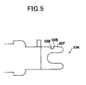
- tapered portion 7 and the engagement portion 8 are formed in each of the two split shape sites 4E and 4F of the inserting end portion 4C, for example, as shown in FIG. 5, a simple configuration may also naturally be adopted whereby a tapered portion 107, an engagement portion 108 and a recess 109 are formed in either one of the regions only. In this case, only one of the latch protrusions 3C needs be provided inside the insertion groove 3B, on the side corresponding to the recess 109. Further, a simpler configuration may be adopted for the inserting end portion 4C by omitting the tapered portion 7.
- the antenna coil device of the embodiment of this invention since a notch 10 is formed in a region of the terminal board 5 facing each of the sites 4E and 4F formed in the split shape of the inserting end portion 4C, and the region of the inserting end portion 4C that faces a portion of the central flat portion 5G of the terminal board 5 in which the notch 10 is formed is a latch recess 4D (see FIG. 2), the stray capacitance between the terminal board 4 and the terminal board 5 is reduced in comparison to the conventional device. It is therefore possible to provide a device that has a higher self resonant frequency as an antenna coil device than the conventional device.
- the antenna coil device of this embodiment since a configuration is adopted in which one end side of a terminal board to be inserted into a base member is formed so that it can bend in a lateral direction with respect to the insertion direction, an operation to insert the terminal board into the base member is easily performed, enabling assembly work to be carried out with a high degree of efficiency. Further, since a latch portion that latches together a terminal board and the base member is provided to surely fasten the terminal board to the base member, a highly reliable antenna coil device can be provided that surely prevents the terminal board that was inserted into the base member from easily dislodging after assembly.
- a coil portion 12 having a lead wire 2 wound around a magnetic core 1 is mounted on a case 3 made of plastic resin, and on one side of the case 3, terminal boards 4 and 5 that electrically connect one end and the other end of the lead wire 2 of the coil portion 12 to an external device are placed in a protruding manner.
- a latch recess 4D is formed in an inserting end portion 4C of the terminal board 4 to form a tip portion into split shape sites 4E and 4F.
- a tapered portion 7 is formed on the outside of the split shape sites 4E and 4F, and an end portion of the tapered portion 7 joins an engagement portion 8 that is formed in a protruding manner in the lateral direction of the inserting end portion 4C.
Landscapes
- Engineering & Computer Science (AREA)
- Power Engineering (AREA)
- Coils Or Transformers For Communication (AREA)
- Details Of Aerials (AREA)
Applications Claiming Priority (1)
| Application Number | Priority Date | Filing Date | Title |
|---|---|---|---|
| JP2005132154A JP4270569B2 (ja) | 2005-04-28 | 2005-04-28 | アンテナ用コイル装置 |
Publications (3)
| Publication Number | Publication Date |
|---|---|
| EP1717823A2 true EP1717823A2 (de) | 2006-11-02 |
| EP1717823A3 EP1717823A3 (de) | 2013-04-24 |
| EP1717823B1 EP1717823B1 (de) | 2016-11-16 |
Family
ID=36644938
Family Applications (1)
| Application Number | Title | Priority Date | Filing Date |
|---|---|---|---|
| EP06008566.9A Expired - Lifetime EP1717823B1 (de) | 2005-04-28 | 2006-04-25 | Antennenspulenvorrichtung |
Country Status (3)
| Country | Link |
|---|---|
| US (1) | US7289081B2 (de) |
| EP (1) | EP1717823B1 (de) |
| JP (1) | JP4270569B2 (de) |
Cited By (1)
| Publication number | Priority date | Publication date | Assignee | Title |
|---|---|---|---|---|
| WO2016071498A1 (de) * | 2014-11-06 | 2016-05-12 | Hirschmann Car Communication Gmbh | Kontaktierungspin aus kupferdraht |
Families Citing this family (5)
| Publication number | Priority date | Publication date | Assignee | Title |
|---|---|---|---|---|
| JP2008205898A (ja) * | 2007-02-21 | 2008-09-04 | Nippon Soken Inc | アンテナモジュール |
| JP2009118270A (ja) * | 2007-11-07 | 2009-05-28 | Sumida Corporation | アンテナ用コイル装置 |
| JP5027761B2 (ja) * | 2008-08-21 | 2012-09-19 | メタウォーター株式会社 | 覆蓋装置及びその使用方法 |
| JP2015201260A (ja) * | 2014-04-04 | 2015-11-12 | 矢崎総業株式会社 | コネクタ装置 |
| USD920912S1 (en) | 2019-01-23 | 2021-06-01 | Sumida Corporation | Core component |
Family Cites Families (7)
| Publication number | Priority date | Publication date | Assignee | Title |
|---|---|---|---|---|
| US3371302A (en) * | 1965-04-23 | 1968-02-27 | Dynamic Instr Corp | Power supply and improved transformer structure therefor |
| US4275400A (en) * | 1977-08-08 | 1981-06-23 | Masashi Miyakoshi | Antenna coil and its support structure mounting |
| JPH09293550A (ja) * | 1996-04-25 | 1997-11-11 | Nichifu Co Ltd | タブ端子 |
| JPH10189350A (ja) * | 1996-12-24 | 1998-07-21 | Tokin Corp | チョークコイル |
| US6010362A (en) * | 1997-07-31 | 2000-01-04 | The Whitaker Corporation | Transformer board mount |
| US5959587A (en) * | 1997-09-12 | 1999-09-28 | Ppg Industries Ohio, Inc. | On the glass antenna system |
| JP4018608B2 (ja) * | 2003-09-08 | 2007-12-05 | セントラル硝子株式会社 | アンテナ用コイル装置 |
-
2005
- 2005-04-28 JP JP2005132154A patent/JP4270569B2/ja not_active Expired - Lifetime
-
2006
- 2006-04-24 US US11/409,122 patent/US7289081B2/en active Active
- 2006-04-25 EP EP06008566.9A patent/EP1717823B1/de not_active Expired - Lifetime
Cited By (2)
| Publication number | Priority date | Publication date | Assignee | Title |
|---|---|---|---|---|
| WO2016071498A1 (de) * | 2014-11-06 | 2016-05-12 | Hirschmann Car Communication Gmbh | Kontaktierungspin aus kupferdraht |
| CN107078443A (zh) * | 2014-11-06 | 2017-08-18 | 赫希曼汽车通讯有限公司 | 由铜线制成的接通销 |
Also Published As
| Publication number | Publication date |
|---|---|
| US20060246787A1 (en) | 2006-11-02 |
| JP2006311281A (ja) | 2006-11-09 |
| EP1717823B1 (de) | 2016-11-16 |
| EP1717823A3 (de) | 2013-04-24 |
| JP4270569B2 (ja) | 2009-06-03 |
| US7289081B2 (en) | 2007-10-30 |
Similar Documents
| Publication | Publication Date | Title |
|---|---|---|
| US6375510B2 (en) | Electrical noise-reducing assembly and member | |
| KR101667231B1 (ko) | 루프 톱 안테나, 특히 관련 플러그형 연결 장치를 구비한 자동차 루프 톱 안테나 | |
| US7318742B2 (en) | Shield terminal for coaxial cable | |
| GB2321796A (en) | Ultrasonic cable connection and cable clamp | |
| CN101926062A (zh) | 同轴连接器以及同轴连接器的组装方法 | |
| KR20000034964A (ko) | 스위치 부착 동축커넥터 | |
| EP1122825B1 (de) | Auf einem Substrat montierter Kontaktstift | |
| US7755232B2 (en) | DC motor with suppressor | |
| EP1717823B1 (de) | Antennenspulenvorrichtung | |
| US7377812B2 (en) | Electrical connector | |
| TWI733851B (zh) | 同軸連接器、高頻單元及接收裝置 | |
| EP2642601A1 (de) | Steckverbinder zur verwendung unter hochspannung | |
| JP4377736B2 (ja) | シールド電線用コネクタおよびそのシールド電線との接続方法 | |
| JP3321566B2 (ja) | ケーブル取付構造 | |
| US7468705B2 (en) | Anti-resonant circuit arrangement | |
| JP2006107809A (ja) | 車両用ワイヤハーネスをアース及び固定するための方法及びアースコネクタ | |
| US8277261B2 (en) | Electrical connector | |
| US7708591B2 (en) | Shield connector | |
| JP6395263B2 (ja) | アンテナ装置およびそれを備えた車両 | |
| JP2000294335A (ja) | コネクタの係止構造 | |
| JP3378751B2 (ja) | 接続端子 | |
| TWI394329B (zh) | 端子結構 | |
| JP2002008743A (ja) | 電気接続装置 | |
| JP4700716B2 (ja) | 車両用アンテナのキャッチャに嵌合するコネクタ | |
| CN221861429U (zh) | 一种线圈电连接装置和感性器件 |
Legal Events
| Date | Code | Title | Description |
|---|---|---|---|
| PUAI | Public reference made under article 153(3) epc to a published international application that has entered the european phase |
Free format text: ORIGINAL CODE: 0009012 |
|
| 17P | Request for examination filed |
Effective date: 20060425 |
|
| AK | Designated contracting states |
Kind code of ref document: A2 Designated state(s): AT BE BG CH CY CZ DE DK EE ES FI FR GB GR HU IE IS IT LI LT LU LV MC NL PL PT RO SE SI SK TR |
|
| AX | Request for extension of the european patent |
Extension state: AL BA HR MK YU |
|
| PUAL | Search report despatched |
Free format text: ORIGINAL CODE: 0009013 |
|
| AK | Designated contracting states |
Kind code of ref document: A3 Designated state(s): AT BE BG CH CY CZ DE DK EE ES FI FR GB GR HU IE IS IT LI LT LU LV MC NL PL PT RO SE SI SK TR |
|
| AX | Request for extension of the european patent |
Extension state: AL BA HR MK YU |
|
| RIC1 | Information provided on ipc code assigned before grant |
Ipc: H01F 37/00 20060101ALN20130319BHEP Ipc: H01F 5/04 20060101AFI20130319BHEP Ipc: H01R 4/24 20060101ALN20130319BHEP Ipc: H01F 17/04 20060101ALN20130319BHEP |
|
| AKX | Designation fees paid |
Designated state(s): AT BE BG CH CY CZ DE DK EE ES FI FR GB GR HU IE IS IT LI LT LU LV MC NL PL PT RO SE SI SK TR |
|
| GRAJ | Information related to disapproval of communication of intention to grant by the applicant or resumption of examination proceedings by the epo deleted |
Free format text: ORIGINAL CODE: EPIDOSDIGR1 |
|
| GRAP | Despatch of communication of intention to grant a patent |
Free format text: ORIGINAL CODE: EPIDOSNIGR1 |
|
| RIC1 | Information provided on ipc code assigned before grant |
Ipc: H01F 17/04 20060101ALN20160601BHEP Ipc: H01R 4/24 20060101ALN20160601BHEP Ipc: H01F 37/00 20060101ALN20160601BHEP Ipc: H01F 5/04 20060101AFI20160601BHEP |
|
| INTG | Intention to grant announced |
Effective date: 20160621 |
|
| RIN1 | Information on inventor provided before grant (corrected) |
Inventor name: MITO, TOMOKO Inventor name: SAITO, MASAKI |
|
| GRAS | Grant fee paid |
Free format text: ORIGINAL CODE: EPIDOSNIGR3 |
|
| GRAA | (expected) grant |
Free format text: ORIGINAL CODE: 0009210 |
|
| RAP1 | Party data changed (applicant data changed or rights of an application transferred) |
Owner name: SUMIDA CORPORATION |
|
| RIN1 | Information on inventor provided before grant (corrected) |
Inventor name: SAITO, MASAKI Inventor name: MITO, TOMOKO |
|
| AK | Designated contracting states |
Kind code of ref document: B1 Designated state(s): AT BE BG CH CY CZ DE DK EE ES FI FR GB GR HU IE IS IT LI LT LU LV MC NL PL PT RO SE SI SK TR |
|
| REG | Reference to a national code |
Ref country code: GB Ref legal event code: FG4D |
|
| REG | Reference to a national code |
Ref country code: CH Ref legal event code: EP |
|
| REG | Reference to a national code |
Ref country code: IE Ref legal event code: FG4D |
|
| REG | Reference to a national code |
Ref country code: AT Ref legal event code: REF Ref document number: 846595 Country of ref document: AT Kind code of ref document: T Effective date: 20161215 |
|
| REG | Reference to a national code |
Ref country code: DE Ref legal event code: R096 Ref document number: 602006050907 Country of ref document: DE |
|
| PG25 | Lapsed in a contracting state [announced via postgrant information from national office to epo] |
Ref country code: LV Free format text: LAPSE BECAUSE OF FAILURE TO SUBMIT A TRANSLATION OF THE DESCRIPTION OR TO PAY THE FEE WITHIN THE PRESCRIBED TIME-LIMIT Effective date: 20161116 |
|
| REG | Reference to a national code |
Ref country code: NL Ref legal event code: MP Effective date: 20161116 |
|
| REG | Reference to a national code |
Ref country code: LT Ref legal event code: MG4D |
|
| REG | Reference to a national code |
Ref country code: AT Ref legal event code: MK05 Ref document number: 846595 Country of ref document: AT Kind code of ref document: T Effective date: 20161116 |
|
| REG | Reference to a national code |
Ref country code: FR Ref legal event code: PLFP Year of fee payment: 12 |
|
| PG25 | Lapsed in a contracting state [announced via postgrant information from national office to epo] |
Ref country code: LT Free format text: LAPSE BECAUSE OF FAILURE TO SUBMIT A TRANSLATION OF THE DESCRIPTION OR TO PAY THE FEE WITHIN THE PRESCRIBED TIME-LIMIT Effective date: 20161116 Ref country code: SE Free format text: LAPSE BECAUSE OF FAILURE TO SUBMIT A TRANSLATION OF THE DESCRIPTION OR TO PAY THE FEE WITHIN THE PRESCRIBED TIME-LIMIT Effective date: 20161116 Ref country code: GR Free format text: LAPSE BECAUSE OF FAILURE TO SUBMIT A TRANSLATION OF THE DESCRIPTION OR TO PAY THE FEE WITHIN THE PRESCRIBED TIME-LIMIT Effective date: 20170217 Ref country code: NL Free format text: LAPSE BECAUSE OF FAILURE TO SUBMIT A TRANSLATION OF THE DESCRIPTION OR TO PAY THE FEE WITHIN THE PRESCRIBED TIME-LIMIT Effective date: 20161116 |
|
| PG25 | Lapsed in a contracting state [announced via postgrant information from national office to epo] |
Ref country code: PL Free format text: LAPSE BECAUSE OF FAILURE TO SUBMIT A TRANSLATION OF THE DESCRIPTION OR TO PAY THE FEE WITHIN THE PRESCRIBED TIME-LIMIT Effective date: 20161116 Ref country code: PT Free format text: LAPSE BECAUSE OF FAILURE TO SUBMIT A TRANSLATION OF THE DESCRIPTION OR TO PAY THE FEE WITHIN THE PRESCRIBED TIME-LIMIT Effective date: 20170316 Ref country code: ES Free format text: LAPSE BECAUSE OF FAILURE TO SUBMIT A TRANSLATION OF THE DESCRIPTION OR TO PAY THE FEE WITHIN THE PRESCRIBED TIME-LIMIT Effective date: 20161116 Ref country code: FI Free format text: LAPSE BECAUSE OF FAILURE TO SUBMIT A TRANSLATION OF THE DESCRIPTION OR TO PAY THE FEE WITHIN THE PRESCRIBED TIME-LIMIT Effective date: 20161116 Ref country code: AT Free format text: LAPSE BECAUSE OF FAILURE TO SUBMIT A TRANSLATION OF THE DESCRIPTION OR TO PAY THE FEE WITHIN THE PRESCRIBED TIME-LIMIT Effective date: 20161116 |
|
| PG25 | Lapsed in a contracting state [announced via postgrant information from national office to epo] |
Ref country code: CZ Free format text: LAPSE BECAUSE OF FAILURE TO SUBMIT A TRANSLATION OF THE DESCRIPTION OR TO PAY THE FEE WITHIN THE PRESCRIBED TIME-LIMIT Effective date: 20161116 Ref country code: RO Free format text: LAPSE BECAUSE OF FAILURE TO SUBMIT A TRANSLATION OF THE DESCRIPTION OR TO PAY THE FEE WITHIN THE PRESCRIBED TIME-LIMIT Effective date: 20161116 Ref country code: EE Free format text: LAPSE BECAUSE OF FAILURE TO SUBMIT A TRANSLATION OF THE DESCRIPTION OR TO PAY THE FEE WITHIN THE PRESCRIBED TIME-LIMIT Effective date: 20161116 Ref country code: SK Free format text: LAPSE BECAUSE OF FAILURE TO SUBMIT A TRANSLATION OF THE DESCRIPTION OR TO PAY THE FEE WITHIN THE PRESCRIBED TIME-LIMIT Effective date: 20161116 Ref country code: DK Free format text: LAPSE BECAUSE OF FAILURE TO SUBMIT A TRANSLATION OF THE DESCRIPTION OR TO PAY THE FEE WITHIN THE PRESCRIBED TIME-LIMIT Effective date: 20161116 |
|
| REG | Reference to a national code |
Ref country code: DE Ref legal event code: R097 Ref document number: 602006050907 Country of ref document: DE |
|
| PG25 | Lapsed in a contracting state [announced via postgrant information from national office to epo] |
Ref country code: IT Free format text: LAPSE BECAUSE OF FAILURE TO SUBMIT A TRANSLATION OF THE DESCRIPTION OR TO PAY THE FEE WITHIN THE PRESCRIBED TIME-LIMIT Effective date: 20161116 Ref country code: BE Free format text: LAPSE BECAUSE OF FAILURE TO SUBMIT A TRANSLATION OF THE DESCRIPTION OR TO PAY THE FEE WITHIN THE PRESCRIBED TIME-LIMIT Effective date: 20161116 Ref country code: BG Free format text: LAPSE BECAUSE OF FAILURE TO SUBMIT A TRANSLATION OF THE DESCRIPTION OR TO PAY THE FEE WITHIN THE PRESCRIBED TIME-LIMIT Effective date: 20170216 |
|
| PLBE | No opposition filed within time limit |
Free format text: ORIGINAL CODE: 0009261 |
|
| STAA | Information on the status of an ep patent application or granted ep patent |
Free format text: STATUS: NO OPPOSITION FILED WITHIN TIME LIMIT |
|
| 26N | No opposition filed |
Effective date: 20170817 |
|
| PG25 | Lapsed in a contracting state [announced via postgrant information from national office to epo] |
Ref country code: SI Free format text: LAPSE BECAUSE OF FAILURE TO SUBMIT A TRANSLATION OF THE DESCRIPTION OR TO PAY THE FEE WITHIN THE PRESCRIBED TIME-LIMIT Effective date: 20161116 |
|
| REG | Reference to a national code |
Ref country code: CH Ref legal event code: PL |
|
| REG | Reference to a national code |
Ref country code: IE Ref legal event code: MM4A |
|
| PG25 | Lapsed in a contracting state [announced via postgrant information from national office to epo] |
Ref country code: MC Free format text: LAPSE BECAUSE OF FAILURE TO SUBMIT A TRANSLATION OF THE DESCRIPTION OR TO PAY THE FEE WITHIN THE PRESCRIBED TIME-LIMIT Effective date: 20161116 |
|
| PG25 | Lapsed in a contracting state [announced via postgrant information from national office to epo] |
Ref country code: LU Free format text: LAPSE BECAUSE OF NON-PAYMENT OF DUE FEES Effective date: 20170425 Ref country code: LI Free format text: LAPSE BECAUSE OF NON-PAYMENT OF DUE FEES Effective date: 20170430 Ref country code: CH Free format text: LAPSE BECAUSE OF NON-PAYMENT OF DUE FEES Effective date: 20170430 |
|
| REG | Reference to a national code |
Ref country code: FR Ref legal event code: PLFP Year of fee payment: 13 |
|
| PG25 | Lapsed in a contracting state [announced via postgrant information from national office to epo] |
Ref country code: IE Free format text: LAPSE BECAUSE OF NON-PAYMENT OF DUE FEES Effective date: 20170425 |
|
| PG25 | Lapsed in a contracting state [announced via postgrant information from national office to epo] |
Ref country code: HU Free format text: LAPSE BECAUSE OF FAILURE TO SUBMIT A TRANSLATION OF THE DESCRIPTION OR TO PAY THE FEE WITHIN THE PRESCRIBED TIME-LIMIT; INVALID AB INITIO Effective date: 20060425 |
|
| PG25 | Lapsed in a contracting state [announced via postgrant information from national office to epo] |
Ref country code: CY Free format text: LAPSE BECAUSE OF NON-PAYMENT OF DUE FEES Effective date: 20161116 |
|
| PG25 | Lapsed in a contracting state [announced via postgrant information from national office to epo] |
Ref country code: TR Free format text: LAPSE BECAUSE OF FAILURE TO SUBMIT A TRANSLATION OF THE DESCRIPTION OR TO PAY THE FEE WITHIN THE PRESCRIBED TIME-LIMIT Effective date: 20161116 |
|
| PG25 | Lapsed in a contracting state [announced via postgrant information from national office to epo] |
Ref country code: IS Free format text: LAPSE BECAUSE OF FAILURE TO SUBMIT A TRANSLATION OF THE DESCRIPTION OR TO PAY THE FEE WITHIN THE PRESCRIBED TIME-LIMIT Effective date: 20170316 |
|
| PGFP | Annual fee paid to national office [announced via postgrant information from national office to epo] |
Ref country code: DE Payment date: 20250422 Year of fee payment: 20 |
|
| PGFP | Annual fee paid to national office [announced via postgrant information from national office to epo] |
Ref country code: GB Payment date: 20250418 Year of fee payment: 20 |
|
| PGFP | Annual fee paid to national office [announced via postgrant information from national office to epo] |
Ref country code: FR Payment date: 20250423 Year of fee payment: 20 |