EP1714818A1 - Doppelkupplungsgetriebe - Google Patents
Doppelkupplungsgetriebe Download PDFInfo
- Publication number
- EP1714818A1 EP1714818A1 EP05103119A EP05103119A EP1714818A1 EP 1714818 A1 EP1714818 A1 EP 1714818A1 EP 05103119 A EP05103119 A EP 05103119A EP 05103119 A EP05103119 A EP 05103119A EP 1714818 A1 EP1714818 A1 EP 1714818A1
- Authority
- EP
- European Patent Office
- Prior art keywords
- clutch
- drive unit
- dual
- gear
- shaft
- Prior art date
- Legal status (The legal status is an assumption and is not a legal conclusion. Google has not performed a legal analysis and makes no representation as to the accuracy of the status listed.)
- Granted
Links
Images

Classifications
-
- B—PERFORMING OPERATIONS; TRANSPORTING
- B60—VEHICLES IN GENERAL
- B60K—ARRANGEMENT OR MOUNTING OF PROPULSION UNITS OR OF TRANSMISSIONS IN VEHICLES; ARRANGEMENT OR MOUNTING OF PLURAL DIVERSE PRIME-MOVERS IN VEHICLES; AUXILIARY DRIVES FOR VEHICLES; INSTRUMENTATION OR DASHBOARDS FOR VEHICLES; ARRANGEMENTS IN CONNECTION WITH COOLING, AIR INTAKE, GAS EXHAUST OR FUEL SUPPLY OF PROPULSION UNITS IN VEHICLES
- B60K6/00—Arrangement or mounting of plural diverse prime-movers for mutual or common propulsion, e.g. hybrid propulsion systems comprising electric motors and internal combustion engines ; Control systems therefor, i.e. systems controlling two or more prime movers, or controlling one of these prime movers and any of the transmission, drive or drive units Informative references: mechanical gearings with secondary electric drive F16H3/72; arrangements for handling mechanical energy structurally associated with the dynamo-electric machine H02K7/00; machines comprising structurally interrelated motor and generator parts H02K51/00; dynamo-electric machines not otherwise provided for in H02K see H02K99/00
- B60K6/20—Arrangement or mounting of plural diverse prime-movers for mutual or common propulsion, e.g. hybrid propulsion systems comprising electric motors and internal combustion engines ; Control systems therefor, i.e. systems controlling two or more prime movers, or controlling one of these prime movers and any of the transmission, drive or drive units Informative references: mechanical gearings with secondary electric drive F16H3/72; arrangements for handling mechanical energy structurally associated with the dynamo-electric machine H02K7/00; machines comprising structurally interrelated motor and generator parts H02K51/00; dynamo-electric machines not otherwise provided for in H02K see H02K99/00 the prime-movers consisting of electric motors and internal combustion engines, e.g. HEVs
- B60K6/22—Arrangement or mounting of plural diverse prime-movers for mutual or common propulsion, e.g. hybrid propulsion systems comprising electric motors and internal combustion engines ; Control systems therefor, i.e. systems controlling two or more prime movers, or controlling one of these prime movers and any of the transmission, drive or drive units Informative references: mechanical gearings with secondary electric drive F16H3/72; arrangements for handling mechanical energy structurally associated with the dynamo-electric machine H02K7/00; machines comprising structurally interrelated motor and generator parts H02K51/00; dynamo-electric machines not otherwise provided for in H02K see H02K99/00 the prime-movers consisting of electric motors and internal combustion engines, e.g. HEVs characterised by apparatus, components or means specially adapted for HEVs
- B60K6/40—Arrangement or mounting of plural diverse prime-movers for mutual or common propulsion, e.g. hybrid propulsion systems comprising electric motors and internal combustion engines ; Control systems therefor, i.e. systems controlling two or more prime movers, or controlling one of these prime movers and any of the transmission, drive or drive units Informative references: mechanical gearings with secondary electric drive F16H3/72; arrangements for handling mechanical energy structurally associated with the dynamo-electric machine H02K7/00; machines comprising structurally interrelated motor and generator parts H02K51/00; dynamo-electric machines not otherwise provided for in H02K see H02K99/00 the prime-movers consisting of electric motors and internal combustion engines, e.g. HEVs characterised by apparatus, components or means specially adapted for HEVs characterised by the assembly or relative disposition of components
-
- B—PERFORMING OPERATIONS; TRANSPORTING
- B60—VEHICLES IN GENERAL
- B60K—ARRANGEMENT OR MOUNTING OF PROPULSION UNITS OR OF TRANSMISSIONS IN VEHICLES; ARRANGEMENT OR MOUNTING OF PLURAL DIVERSE PRIME-MOVERS IN VEHICLES; AUXILIARY DRIVES FOR VEHICLES; INSTRUMENTATION OR DASHBOARDS FOR VEHICLES; ARRANGEMENTS IN CONNECTION WITH COOLING, AIR INTAKE, GAS EXHAUST OR FUEL SUPPLY OF PROPULSION UNITS IN VEHICLES
- B60K6/00—Arrangement or mounting of plural diverse prime-movers for mutual or common propulsion, e.g. hybrid propulsion systems comprising electric motors and internal combustion engines ; Control systems therefor, i.e. systems controlling two or more prime movers, or controlling one of these prime movers and any of the transmission, drive or drive units Informative references: mechanical gearings with secondary electric drive F16H3/72; arrangements for handling mechanical energy structurally associated with the dynamo-electric machine H02K7/00; machines comprising structurally interrelated motor and generator parts H02K51/00; dynamo-electric machines not otherwise provided for in H02K see H02K99/00
- B60K6/20—Arrangement or mounting of plural diverse prime-movers for mutual or common propulsion, e.g. hybrid propulsion systems comprising electric motors and internal combustion engines ; Control systems therefor, i.e. systems controlling two or more prime movers, or controlling one of these prime movers and any of the transmission, drive or drive units Informative references: mechanical gearings with secondary electric drive F16H3/72; arrangements for handling mechanical energy structurally associated with the dynamo-electric machine H02K7/00; machines comprising structurally interrelated motor and generator parts H02K51/00; dynamo-electric machines not otherwise provided for in H02K see H02K99/00 the prime-movers consisting of electric motors and internal combustion engines, e.g. HEVs
- B60K6/22—Arrangement or mounting of plural diverse prime-movers for mutual or common propulsion, e.g. hybrid propulsion systems comprising electric motors and internal combustion engines ; Control systems therefor, i.e. systems controlling two or more prime movers, or controlling one of these prime movers and any of the transmission, drive or drive units Informative references: mechanical gearings with secondary electric drive F16H3/72; arrangements for handling mechanical energy structurally associated with the dynamo-electric machine H02K7/00; machines comprising structurally interrelated motor and generator parts H02K51/00; dynamo-electric machines not otherwise provided for in H02K see H02K99/00 the prime-movers consisting of electric motors and internal combustion engines, e.g. HEVs characterised by apparatus, components or means specially adapted for HEVs
- B60K6/36—Arrangement or mounting of plural diverse prime-movers for mutual or common propulsion, e.g. hybrid propulsion systems comprising electric motors and internal combustion engines ; Control systems therefor, i.e. systems controlling two or more prime movers, or controlling one of these prime movers and any of the transmission, drive or drive units Informative references: mechanical gearings with secondary electric drive F16H3/72; arrangements for handling mechanical energy structurally associated with the dynamo-electric machine H02K7/00; machines comprising structurally interrelated motor and generator parts H02K51/00; dynamo-electric machines not otherwise provided for in H02K see H02K99/00 the prime-movers consisting of electric motors and internal combustion engines, e.g. HEVs characterised by apparatus, components or means specially adapted for HEVs characterised by the transmission gearings
-
- B—PERFORMING OPERATIONS; TRANSPORTING
- B60—VEHICLES IN GENERAL
- B60K—ARRANGEMENT OR MOUNTING OF PROPULSION UNITS OR OF TRANSMISSIONS IN VEHICLES; ARRANGEMENT OR MOUNTING OF PLURAL DIVERSE PRIME-MOVERS IN VEHICLES; AUXILIARY DRIVES FOR VEHICLES; INSTRUMENTATION OR DASHBOARDS FOR VEHICLES; ARRANGEMENTS IN CONNECTION WITH COOLING, AIR INTAKE, GAS EXHAUST OR FUEL SUPPLY OF PROPULSION UNITS IN VEHICLES
- B60K6/00—Arrangement or mounting of plural diverse prime-movers for mutual or common propulsion, e.g. hybrid propulsion systems comprising electric motors and internal combustion engines ; Control systems therefor, i.e. systems controlling two or more prime movers, or controlling one of these prime movers and any of the transmission, drive or drive units Informative references: mechanical gearings with secondary electric drive F16H3/72; arrangements for handling mechanical energy structurally associated with the dynamo-electric machine H02K7/00; machines comprising structurally interrelated motor and generator parts H02K51/00; dynamo-electric machines not otherwise provided for in H02K see H02K99/00
- B60K6/20—Arrangement or mounting of plural diverse prime-movers for mutual or common propulsion, e.g. hybrid propulsion systems comprising electric motors and internal combustion engines ; Control systems therefor, i.e. systems controlling two or more prime movers, or controlling one of these prime movers and any of the transmission, drive or drive units Informative references: mechanical gearings with secondary electric drive F16H3/72; arrangements for handling mechanical energy structurally associated with the dynamo-electric machine H02K7/00; machines comprising structurally interrelated motor and generator parts H02K51/00; dynamo-electric machines not otherwise provided for in H02K see H02K99/00 the prime-movers consisting of electric motors and internal combustion engines, e.g. HEVs
- B60K6/42—Arrangement or mounting of plural diverse prime-movers for mutual or common propulsion, e.g. hybrid propulsion systems comprising electric motors and internal combustion engines ; Control systems therefor, i.e. systems controlling two or more prime movers, or controlling one of these prime movers and any of the transmission, drive or drive units Informative references: mechanical gearings with secondary electric drive F16H3/72; arrangements for handling mechanical energy structurally associated with the dynamo-electric machine H02K7/00; machines comprising structurally interrelated motor and generator parts H02K51/00; dynamo-electric machines not otherwise provided for in H02K see H02K99/00 the prime-movers consisting of electric motors and internal combustion engines, e.g. HEVs characterised by the architecture of the hybrid electric vehicle
- B60K6/46—Series type
-
- B—PERFORMING OPERATIONS; TRANSPORTING
- B60—VEHICLES IN GENERAL
- B60K—ARRANGEMENT OR MOUNTING OF PROPULSION UNITS OR OF TRANSMISSIONS IN VEHICLES; ARRANGEMENT OR MOUNTING OF PLURAL DIVERSE PRIME-MOVERS IN VEHICLES; AUXILIARY DRIVES FOR VEHICLES; INSTRUMENTATION OR DASHBOARDS FOR VEHICLES; ARRANGEMENTS IN CONNECTION WITH COOLING, AIR INTAKE, GAS EXHAUST OR FUEL SUPPLY OF PROPULSION UNITS IN VEHICLES
- B60K6/00—Arrangement or mounting of plural diverse prime-movers for mutual or common propulsion, e.g. hybrid propulsion systems comprising electric motors and internal combustion engines ; Control systems therefor, i.e. systems controlling two or more prime movers, or controlling one of these prime movers and any of the transmission, drive or drive units Informative references: mechanical gearings with secondary electric drive F16H3/72; arrangements for handling mechanical energy structurally associated with the dynamo-electric machine H02K7/00; machines comprising structurally interrelated motor and generator parts H02K51/00; dynamo-electric machines not otherwise provided for in H02K see H02K99/00
- B60K6/20—Arrangement or mounting of plural diverse prime-movers for mutual or common propulsion, e.g. hybrid propulsion systems comprising electric motors and internal combustion engines ; Control systems therefor, i.e. systems controlling two or more prime movers, or controlling one of these prime movers and any of the transmission, drive or drive units Informative references: mechanical gearings with secondary electric drive F16H3/72; arrangements for handling mechanical energy structurally associated with the dynamo-electric machine H02K7/00; machines comprising structurally interrelated motor and generator parts H02K51/00; dynamo-electric machines not otherwise provided for in H02K see H02K99/00 the prime-movers consisting of electric motors and internal combustion engines, e.g. HEVs
- B60K6/42—Arrangement or mounting of plural diverse prime-movers for mutual or common propulsion, e.g. hybrid propulsion systems comprising electric motors and internal combustion engines ; Control systems therefor, i.e. systems controlling two or more prime movers, or controlling one of these prime movers and any of the transmission, drive or drive units Informative references: mechanical gearings with secondary electric drive F16H3/72; arrangements for handling mechanical energy structurally associated with the dynamo-electric machine H02K7/00; machines comprising structurally interrelated motor and generator parts H02K51/00; dynamo-electric machines not otherwise provided for in H02K see H02K99/00 the prime-movers consisting of electric motors and internal combustion engines, e.g. HEVs characterised by the architecture of the hybrid electric vehicle
- B60K6/48—Parallel type
-
- B—PERFORMING OPERATIONS; TRANSPORTING
- B60—VEHICLES IN GENERAL
- B60K—ARRANGEMENT OR MOUNTING OF PROPULSION UNITS OR OF TRANSMISSIONS IN VEHICLES; ARRANGEMENT OR MOUNTING OF PLURAL DIVERSE PRIME-MOVERS IN VEHICLES; AUXILIARY DRIVES FOR VEHICLES; INSTRUMENTATION OR DASHBOARDS FOR VEHICLES; ARRANGEMENTS IN CONNECTION WITH COOLING, AIR INTAKE, GAS EXHAUST OR FUEL SUPPLY OF PROPULSION UNITS IN VEHICLES
- B60K6/00—Arrangement or mounting of plural diverse prime-movers for mutual or common propulsion, e.g. hybrid propulsion systems comprising electric motors and internal combustion engines ; Control systems therefor, i.e. systems controlling two or more prime movers, or controlling one of these prime movers and any of the transmission, drive or drive units Informative references: mechanical gearings with secondary electric drive F16H3/72; arrangements for handling mechanical energy structurally associated with the dynamo-electric machine H02K7/00; machines comprising structurally interrelated motor and generator parts H02K51/00; dynamo-electric machines not otherwise provided for in H02K see H02K99/00
- B60K6/20—Arrangement or mounting of plural diverse prime-movers for mutual or common propulsion, e.g. hybrid propulsion systems comprising electric motors and internal combustion engines ; Control systems therefor, i.e. systems controlling two or more prime movers, or controlling one of these prime movers and any of the transmission, drive or drive units Informative references: mechanical gearings with secondary electric drive F16H3/72; arrangements for handling mechanical energy structurally associated with the dynamo-electric machine H02K7/00; machines comprising structurally interrelated motor and generator parts H02K51/00; dynamo-electric machines not otherwise provided for in H02K see H02K99/00 the prime-movers consisting of electric motors and internal combustion engines, e.g. HEVs
- B60K6/50—Architecture of the driveline characterised by arrangement or kind of transmission units
- B60K6/54—Transmission for changing ratio
- B60K6/547—Transmission for changing ratio the transmission being a stepped gearing
-
- B—PERFORMING OPERATIONS; TRANSPORTING
- B60—VEHICLES IN GENERAL
- B60Y—INDEXING SCHEME RELATING TO ASPECTS CROSS-CUTTING VEHICLE TECHNOLOGY
- B60Y2400/00—Special features of vehicle units
- B60Y2400/42—Clutches or brakes
- B60Y2400/428—Double clutch arrangements; Dual clutches
-
- F—MECHANICAL ENGINEERING; LIGHTING; HEATING; WEAPONS; BLASTING
- F16—ENGINEERING ELEMENTS AND UNITS; GENERAL MEASURES FOR PRODUCING AND MAINTAINING EFFECTIVE FUNCTIONING OF MACHINES OR INSTALLATIONS; THERMAL INSULATION IN GENERAL
- F16H—GEARING
- F16H3/00—Toothed gearings for conveying rotary motion with variable gear ratio or for reversing rotary motion
- F16H3/006—Toothed gearings for conveying rotary motion with variable gear ratio or for reversing rotary motion power being selectively transmitted by either one of the parallel flow paths
-
- Y—GENERAL TAGGING OF NEW TECHNOLOGICAL DEVELOPMENTS; GENERAL TAGGING OF CROSS-SECTIONAL TECHNOLOGIES SPANNING OVER SEVERAL SECTIONS OF THE IPC; TECHNICAL SUBJECTS COVERED BY FORMER USPC CROSS-REFERENCE ART COLLECTIONS [XRACs] AND DIGESTS
- Y02—TECHNOLOGIES OR APPLICATIONS FOR MITIGATION OR ADAPTATION AGAINST CLIMATE CHANGE
- Y02T—CLIMATE CHANGE MITIGATION TECHNOLOGIES RELATED TO TRANSPORTATION
- Y02T10/00—Road transport of goods or passengers
- Y02T10/60—Other road transportation technologies with climate change mitigation effect
- Y02T10/62—Hybrid vehicles
-
- Y—GENERAL TAGGING OF NEW TECHNOLOGICAL DEVELOPMENTS; GENERAL TAGGING OF CROSS-SECTIONAL TECHNOLOGIES SPANNING OVER SEVERAL SECTIONS OF THE IPC; TECHNICAL SUBJECTS COVERED BY FORMER USPC CROSS-REFERENCE ART COLLECTIONS [XRACs] AND DIGESTS
- Y10—TECHNICAL SUBJECTS COVERED BY FORMER USPC
- Y10T—TECHNICAL SUBJECTS COVERED BY FORMER US CLASSIFICATION
- Y10T74/00—Machine element or mechanism
- Y10T74/19—Gearing
- Y10T74/19219—Interchangeably locked
- Y10T74/19223—Disconnectable counter shaft
-
- Y—GENERAL TAGGING OF NEW TECHNOLOGICAL DEVELOPMENTS; GENERAL TAGGING OF CROSS-SECTIONAL TECHNOLOGIES SPANNING OVER SEVERAL SECTIONS OF THE IPC; TECHNICAL SUBJECTS COVERED BY FORMER USPC CROSS-REFERENCE ART COLLECTIONS [XRACs] AND DIGESTS
- Y10—TECHNICAL SUBJECTS COVERED BY FORMER USPC
- Y10T—TECHNICAL SUBJECTS COVERED BY FORMER US CLASSIFICATION
- Y10T74/00—Machine element or mechanism
- Y10T74/19—Gearing
- Y10T74/19219—Interchangeably locked
- Y10T74/19228—Multiple concentric clutch shafts
-
- Y—GENERAL TAGGING OF NEW TECHNOLOGICAL DEVELOPMENTS; GENERAL TAGGING OF CROSS-SECTIONAL TECHNOLOGIES SPANNING OVER SEVERAL SECTIONS OF THE IPC; TECHNICAL SUBJECTS COVERED BY FORMER USPC CROSS-REFERENCE ART COLLECTIONS [XRACs] AND DIGESTS
- Y10—TECHNICAL SUBJECTS COVERED BY FORMER USPC
- Y10T—TECHNICAL SUBJECTS COVERED BY FORMER US CLASSIFICATION
- Y10T74/00—Machine element or mechanism
- Y10T74/19—Gearing
- Y10T74/19219—Interchangeably locked
- Y10T74/19233—Plurality of counter shafts
-
- Y—GENERAL TAGGING OF NEW TECHNOLOGICAL DEVELOPMENTS; GENERAL TAGGING OF CROSS-SECTIONAL TECHNOLOGIES SPANNING OVER SEVERAL SECTIONS OF THE IPC; TECHNICAL SUBJECTS COVERED BY FORMER USPC CROSS-REFERENCE ART COLLECTIONS [XRACs] AND DIGESTS
- Y10—TECHNICAL SUBJECTS COVERED BY FORMER USPC
- Y10T—TECHNICAL SUBJECTS COVERED BY FORMER US CLASSIFICATION
- Y10T74/00—Machine element or mechanism
- Y10T74/19—Gearing
- Y10T74/19219—Interchangeably locked
- Y10T74/19284—Meshing assisters
- Y10T74/19288—Double clutch and interposed transmission
Definitions
- the invention relates to a dual-clutch transmission, in particular for a motor vehicle.
- a dual-clutch transmission which comprises a first clutch and a second clutch, which are arranged coaxially with each other and therefore have a common axis of rotation. Furthermore, the dual-clutch transmission comprises a first input shaft and a second input shaft. The first input shaft can be connected to a motor via the first clutch. The second input shaft can be connected to the motor via the second clutch.
- a gear pair consists of a fixed gear and a loose wheel.
- the idler gear is assigned in each case a gearshift clutch, by which the idler gear can be rotatably connected to the shaft on which the idler gear is arranged. With the gearshift clutch closed, the gear pair transmits torque from one of the input shafts to the output shaft.
- the dual-clutch transmission has the US 6,499,370 a first drive unit and a second drive unit.
- the two drive units are each designed as electric machines, which are arranged coaxially to the two clutches and coaxial with the two input shafts.
- the dual-clutch transmission Due to the coaxial arrangement of the two clutches, the two input shafts with the fixed wheels or loose wheels including gearshift clutches arranged thereon and by the coaxially arranged electric machines, the dual-clutch transmission has a comparatively large axial length.
- this can lead to problems. So is the space inside the engine compartment of the vehicle especially then very limited when the dual-clutch transmission is to be installed together with the engine transversely to the direction of travel. The problem of limited space is getting worse, as there is a trend in manual transmissions to increase the number of forward gears.
- An additional forward gear usually means another gear, which is arranged on one of the input shafts and further increases the axial length.
- the invention is therefore based on the object to provide a dual-clutch transmission with two drive units, which has a comparatively small axial length despite a high number of forward gears.
- the first drive unit is arranged coaxially with the first and second clutch and engages the clutches in the radial direction and that the second drive unit has a drive shaft with an axis of rotation which is different from the axis of rotation of the clutches, can a manual transmission with comparatively short realize axial length.
- the arrangement of the first drive unit has virtually no influence on the axial length if the axial extent of the first drive unit is less than the axial extent of the dual clutch arrangement.
- the first drive unit closes as seen in the radial direction of the dual clutch assembly wherein an inner diameter of the first drive unit corresponds approximately to an outer diameter of the dual clutch assembly.
- the second drive shaft can be arranged spatially separated from the clutches and also from the first drive unit. In principle, the arrangement of the second drive unit is freely selectable.
- the axis of rotation of the drive shaft of the second drive unit extends parallel to the axis of rotation of the two clutches.
- Such an arrangement of the two axes of rotation facilitates coupling of the second drive unit to one of the two input shafts or to the at least one output shaft, which is usually parallel to the input shafts.
- the first and second input shafts are arranged coaxially with the axis of rotation of the clutches.
- one of the input shafts is designed as a hollow shaft.
- the first drive unit can be designed as an electric machine with a stator and with a rotor.
- the annular rotor is arranged between the annular stator and the dual clutch arrangement.
- the first drive unit is connected to an input side of the dual clutch assembly.
- the first drive unit is an electric machine with stator and rotor, in this case the rotor is non-rotatably connected to the motor or to a crankshaft of the motor. Consequently, the rotor and crankshaft always have the same speed.
- the first drive unit may be connected to one of the input shafts.
- the rotor is rotatably connected to one of the input shafts.
- the first drive unit is thus connected behind the dual clutch arrangement when viewed from the engine.
- the second drive unit is connected to one of the input shafts.
- the second drive unit should expediently be connected to the other input shaft. This opens up the possibility of independently controlling the speed of the two input shafts via the respective drive unit.
- the rotational speed of an input shaft can be synchronized with the rotational speed of the output shaft, whereby the gearshift clutches can be designed as positive clutches without synchronization unit.
- a torque to assist the engine can be switched by the drive units to the input shafts.
- the second drive unit is connected to the output shaft instead of an input shaft.
- a gear is arranged on the drive shaft of the second drive unit, which meshes with a gear on one of the input shafts.
- the gear on the corresponding input shaft may be a fixed gear or a loose wheel of a gear pair, which is provided for connecting the input shaft to the output shaft. This saves a separate gear for the connection of the second drive unit.
- a sprocket may be arranged on the drive shaft of the drive unit, a sprocket, which is connected via a chain with a sprocket on one of the input shafts. Due to the chain (length, course), the distance of the second drive unit to the axis of rotation of the input shaft is basically freely selectable.
- chain is to be understood here in the sense of closed, circulating traction means.
- a sprocket for a wheel or for a disc that allows a frictional or positive connection of the traction means with the shaft that carries the wheel or disc.
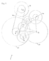
- FIG. 1 shows a dual-clutch transmission, which is designated 1 in its entirety.
- the dual-clutch transmission 1 has a dual-clutch arrangement 2 with a first clutch 3 and a second clutch 4.
- On a flange 5 can be rotationally fixed here only indicated motor 6 to an input side 7 of the dual clutch assembly 2.
- the first clutch 3 and the second clutch 4 have a common axis of rotation 8. Coaxially to this axis of rotation 8, a first input shaft 9 and a second input shaft 10 are arranged. Input shaft 9 is formed as a hollow shaft.
- the first clutch 3 connects in a closed state, the first input shaft 9 with the input side 7 of the dual clutch assembly 2 and with the motor 6.
- the second clutch 4 serves to connect the second input shaft 10 with the motor 6.
- the dual-clutch transmission 1 further has a first output shaft 11 and a second output shaft 12.
- the respective axes of rotation of the two output shafts 11, 12 extend parallel to the axis of rotation 8, but are spaced therefrom.
- To connect the two input shafts 9, 10 with the two output shafts 11, 12 five gear pairs 13, 14, 15, 16, 17 are provided.
- Each gear pair includes a fixed gear and a loose wheel, the fixed gear with the index f and the idler gear with the index I is occupied.
- a fixed gear 13f of the gear pair 13 is arranged, which meshes with a loose wheel 131, which sits on the second output shaft 12.
- only the fixed wheels 13f, 14f, 15f, 16f, 17f of the gear pairs 13 to 17 are arranged on the input shafts 9, 10.
- gearshift clutch 18 On the output shafts 11, 12 a plurality of gearshift clutches 18, 19, 20, 21, 22 are arranged.
- the gear shift clutches are shown here only schematically by rectangles with diagonals drawn, with two partially shift clutches are represented by only one rectangle.
- the gearshift clutch 18 serves to rotatably connect the idler gear 161 associated therewith to the first output shaft 11. If such a rotationally fixed connection between the idler gear 161 and the first output shaft 11 made, the gear pair 16 can transmit a torque from the second input shaft 10 to the first output shaft 11.
- a torque applied to the output shafts 11, 12 can be transmitted to a ring gearwheel 25.
- the ring gear then passes there applied torque to a differential 26, which distributes the torque to the axles 27, 28.
- the dual-clutch transmission 1 comprises a further output shaft, a third output shaft 29.
- This third output shaft 29 has a rotationally fixed gear 30 which is in engagement with the ring gear 25.
- the third output shaft 29 is rotatably connected to a parking gear 31, through which the ring gear 25 can be locked via the gear 30.
- the gears 23, 24, 30 each have a same diameter and lie in a common plane.
- an intermediate shaft 32 is arranged between the first output shaft 11 and the third output shaft 29, an intermediate shaft 32 is arranged.
- the intermediate shaft 32 carries a gear 33 which meshes with the idler gear 14l.
- a gear 34 is also rotatably on the intermediate shaft 32 also arranged. which meshes with a loose wheel 35 on the third output shaft 29.
- the idler gear 35 can be rotatably connected to the third output shaft 29. With engaged gearshift clutch 36, the first forward gear I of the dual-clutch transmission 1 is inserted.
- the gearshift clutch 19 In order to transmit torque in the first forward gear I from the second input shaft 9 to the third output shaft 29, the gearshift clutch 19 is opened or must be opened.
- the idler gear 141 transmits no torque to the first output shaft 11, but serves only the torque transmission from the fixed gear 14f to the gear 33 through which the corresponding torque via the intermediate shaft 32, the gear 34, the now rotationally fixed idler gear 35 on the third output shaft 29 is passed. If, however, the third forward gear III is engaged, transmits the idler gear 14 I due to the now closed gearshift clutch 19, a torque on the first output shaft 11.
- Gearshift clutch 36 must be open.
- the dual-clutch transmission 1 comprises a first drive unit 37 and a second drive unit 38. Both drive units 37, 38 are designed as electric machines.
- the first drive unit 37 or the first electric machine 37 is arranged coaxially with the clutches 3, 4 and surrounds them in the radial direction.
- the axial expansions of the first electric machine 37 correspond approximately to the axial dimensions of the clutches 3, 4 or of the dual clutch arrangement 2, so that the electric machine 37 has no or only a very small influence on the axial length of the dual clutch transmission 1.
- the first electric machine 37 has a stator 39 and a rotor 40.
- Stator 39 and rotor 40 are each annular, wherein the stator 39 engages around the rotor 40 in the radial direction from the outside.
- the rotor 40 in turn, lies on the outside of the dual clutch arrangement 2, viewed in the radial direction.
- the rotor 40 is rotatably connected via a disc-shaped connection 41 with the first input shaft 9.
- the second drive unit 38 or the second electric machine 38 is connected via a toothed or sprocket 42 and via a closed traction means in the form of a chain 43 to the second input shaft 10 (see FIG. In Figure 1, the chain 43 is shown schematically as a double arrow, which should indicate that a connection between the second electric machine 38 and the second input shaft 10 with the gear 42 arranged thereon.
- the electric machines 37, 38 can fulfill a wide variety of tasks in the operation of the dual-clutch transmission 1. For example, they are adapted to synchronize the rotational speed of each associated with its input shaft either with the rotational speed of an output shaft or with a rotational speed of the motor 6. These synchronizations make it possible to form the gear shift clutches in the dual-clutch transmission 1, the first clutch 3 and the second clutch 4 as positive clutches without any slip operation.
- the electric machines 37, 38 may be used to start or start the engine 6 or to assist it at high load. Both electric machines 37, 38 can be operated both as a generator and as a motor.
- the dual-clutch transmission 1 does not provide a mechanical reverse gear.
- a reversing of the motor vehicle equipped with this transmission is realized in that one of the two electric machines 37, 38 or both electric machines rotate in a direction of rotation, which is opposite to the rotation of the motor 6.
- the torque of the first electric machine 37 can be used for reversing the vehicle, wherein the power flow is passed over the gears that are under load even at the first forward gear I.
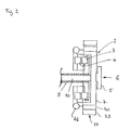
- Figure 3 shows a variant of the dual clutch assembly 2 together with the first electric machine 37, which surrounds the former in the radial direction. While in the embodiment of Figure 1, the rotor 40 is rotatably connected to the first input shaft 9, the rotor 40 is rotatably connected to the input side 7 of the dual clutch assembly 2 here. This means that via the flange 5, the rotor 40 always rotates at the speed of the motor 6. Between the rotor 40 and the two clutches 9, 10, a torsion damper 46 is arranged.
Abstract
Description
- Die Erfindung betrifft ein Doppelkupplungsgetriebe insbesondere für ein Kraftfahrzeug.
- Aus der
US 6,499,370 beispielsweise ist ein Doppelkupplungsgetriebe bekannt, das eine erste Kupplung und eine zweite Kupplung umfasst, die koaxial zueinander angeordnet sind und demzufolge eine gemeinsame Drehachse aufweisen. Des weiteren umfasst das Doppelkupplungsgetriebe eine erste Eingangswelle und eine zweite Eingangswelle. Dabei lässt sich die erste Eingangswelle über die erste Kupplung mit einem Motor verbinden. Die zweite Eingangswelle kann über die zweite Kupplung mit dem Motor verbunden werden. - Über mehrere schaltbare Zahnradpaare lässt sich ein Drehmoment von den Eingangswellen auf eine Ausgangswelle übertragen. Ein Zahnradpaar besteht dabei aus einem Festrad und einem Losrad. Dem Losrad ist jeweils eine Gangschaltkupplung zugeordnet, durch die das Losrad mit der Welle, auf der das Losrad angeordnet ist, drehfest verbunden werden kann. Bei geschlossener Gangschaltkupplung überträgt das Zahnradpaar ein Drehmoment von einer der Eingangswellen auf die Ausgangswelle.
- Um einen seriellen und/oder parallelen Hybridmodus des Doppelkupplungsgetriebes zu ermöglichen, weist das Doppelkupplungsgetriebe der
US 6,499,370 eine erste Antriebseinheit und eine zweite Antriebseinheit auf. Die beiden Antriebseinheiten sind dabei jeweils als Elektromaschinen ausgebildet, die koaxial zu den beiden Kupplungen und koaxial zu den beiden Eingangswellen angeordnet sind. - Durch die koaxiale Anordnung der beiden Kupplungen, der beiden Eingangswellen mit den darauf angeordneten Festrädern bzw. Losrädern inklusive Gangschaltkupplungen sowie durch die dazu koaxial angeordneten Elektromaschinen weist das Doppelkupplungsgetriebe eine vergleichsweise große axiale Baulänge auf. Beim Einbau in ein Kraftfahrzeug mit vorgegebenem Platzangebot kann dies zu Problemen führen. So ist das Platzangebot innerhalb des Motorraumes des Kraftfahrzeugs insbesondere dann sehr begrenzt, wenn das Doppelkupplungsgetriebe gemeinsam mit dem Motor quer zur Fahrrichtung eingebaut werden soll. Das Problem des begrenzten Platzangebots verschärft sich, da bei Schaltgetrieben ein Trend zu beobachten ist, die Anzahl der Vorwärtsgänge zu vergrößern. Ein zusätzlicher Vorwärtsgang bedeutet in der Regel ein weiteres Zahnrad, das auf einer der Eingangswellen angeordnet ist und die axiale Baulänge weiter vergrößert.
- Aus der
DE 198 50 549 ist ein Doppelkupplungsgetriebe mit nur einer Elektromaschine bekannt, die je nach Bedarf durch eine Umschaltvorrichtung auf die erste oder auf die zweite Eingangswelle geschaltet werden kann. Zwar kann durch eine derartige Umschaltvorrichtung eine Elektromaschine eingespart werden. Im Vergleich zu einem Doppelkupplungsgetriebe mit zwei Elektromaschinen, deren paralleler Betrieb beispielsweise bei maximaler Last vorgesehen ist, muss jedoch diese einzelne Elektromaschine größer dimensioniert werden, um eine Leistung bereitzustellen, die der Summe der Einzelleistungen der beiden Elektromaschinen entspricht. Eine derart große Elektromaschine kann jedoch auch wieder zu Packaging-Problemen führen. - Der Erfindung liegt daher die Aufgabe zugrunde, ein Doppelkupplungsgetriebe mit zwei Antriebseinheiten bereitzustellen, das trotz einer hohen Anzahl von Vorwärtsgängen eine vergleichsweise kleine axiale Baulänge aufweist.
- Die der Erfindung zugrunde liegende Aufgabe wird durch das Doppelkupplungsgetriebe mit den Merkmalen des Anspruchs 1 gelöst. Bevorzugte Ausführungsformen können den Unteransprüchen entnommen werden.
- Dadurch, das die erste Antriebseinheit koaxial zu der ersten und zweiten Kupplung angeordnet ist und die Kupplungen in radialer Richtung umgreift und dass die zweite Antriebseinheit eine Antriebswelle mit einer Drehachse aufweist, die von der Drehachse der Kupplungen verschieden ist, lässt sich ein Schaltgetriebe mit vergleichsweise kurzer axialer Baulänge realisieren. Die Anordnung der ersten Antriebseinheit hat praktisch keinen Einfluss auf die axiale Baulänge, wenn die axiale Ausdehnung der ersten Antriebseinheit geringer ist als die axiale Ausdehnung der Doppelkupplungsanordnung. Die erste Antriebseinheit schließt sich in radialer Richtung gesehen an die Doppelkupplungsanordnung an, wobei ein Innendurchmesser der ersten Antriebseinheit in etwa einem Außendurchmesser der Doppelkupplungsanordnung entspricht.
- Da die Antriebswelle der zweiten Antriebseinheit nicht mit der Drehachse der beiden Kupplungen zusammenfällt, kann die zweite Antriebswelle von den Kupplungen und auch von der ersten Antriebseinheit räumlich getrennt angeordnet werden. Dabei ist die Anordnung der zweiten Antriebseinheit grundsätzlich frei wählbar.
- In einem bevorzugten Ausführungsbeispiel verläuft die Drehachse der Antriebswelle der zweiten Antriebseinheit parallel beabstandet zur Drehachse der beiden Kupplungen. Eine derartige Anordnung der beiden Drehachsen erleichtert eine Ankopplung der zweiten Antriebseinheit an eine der beiden Eingangswellen bzw. an die wenigstens eine Ausgangswelle, die üblicherweise parallel zu den Eingangswellen verläuft.
- In einem bevorzugten Ausführungsbeispiel sind die erste und die zweite Eingangswelle koaxial zu der Drehachse der Kupplungen angeordnet. Vorzugsweise ist dabei eine der Eingangswellen als Hohlwelle ausgebildet.
- Die erste Antriebseinheit kann als Elektromaschine mit einem Stator und mit einem Rotor ausgebildet sein. Bei der erfindungsgemäßen Anordnung der ersten Antriebseinheit ist der ringförmige Rotor zwischen dem ringförmigen Stator und der Doppelkupplungsanordnung angeordnet.
- In einem bevorzugten Ausführungsbeispiel ist die erste Antriebseinheit mit einer Eingangsseite der Doppelkupplungsanordnung verbunden. Soweit es sich bei der ersten Antriebseinheit um eine Elektromaschine mit Stator und Rotor handelt, ist in diesem Fall der Rotor drehfest mit dem Motor bzw. mit einer Kurbelwelle des Motors verbunden. Rotor und Kurbelwelle weisen folglich jeweils immer die gleiche Drehzahl auf.
- Alternativ dazu kann die erste Antriebseinheit mit einer der Eingangswellen verbunden sein. In diesem Fall, wenn wieder eine Elektromaschine mit Stator und Rotor als Antriebseinheit zugrunde gelegt wird, ist der Rotor drehfest mit einer der Eingangswellen verbunden. Getriebetechnisch gesehen ist damit die erste Antriebseinheit vom Motor aus gesehen hinter der Doppelkupplungsanordnung geschaltet.
- Vorzugsweise ist die zweite Antriebseinheit mit einer der Eingangswellen verbunden. In dem Ausführungsbeispiel, in dem die erste Antriebseinheit mit einer der Eingangswellen verbunden ist, sollte die zweite Antriebseinheit zweckmäßigerweise mit der anderen Eingangswelle verbunden sein. Dies eröffnet die Möglichkeit, die Drehzahl der beiden Eingangswellen über die jeweilige Antriebseinheit unabhängig voneinander zu steuern. So kann beispielsweise die Drehzahl einer Eingangswelle mit der Drehzahl der Ausgangswelle synchronisiert werden, wodurch die Gangschaltkupplungen als formschlüssige Kupplungen ohne Synchronisationseinheit ausgebildet sein können. Darüber hinaus kann durch die Antriebseinheiten auf die Eingangswellen ein Drehmoment zur Unterstützung des Motors geschaltet werden. Alternativ ist es auch möglich, dass die zweite Antriebseinheit anstatt mit einer Eingangswelle mit der Ausgangswelle verbunden ist.
- Vorzugsweise ist auf der Antriebswelle der zweiten Antriebseinheit ein Zahnrad angeordnet, das mit einem Zahnrad auf einer der Eingangswellen kämmt. Dabei kann das Zahnrad auf der entsprechenden Eingangswelle ein Festrad oder ein Losrad eines Zahnradpaares sein, das zur Verbindung der Eingangswelle mit der Ausgangswelle vorgesehen ist. Dies spart ein gesondertes Zahnrad für die Anbindung der zweiten Antriebseinheit ein.
- Alternativ dazu kann auf der Antriebswelle der Antriebseinheit ein Kettenrad angeordnet sein, das über eine Kette mit einem Kettenrad auf einer der Eingangswellen verbunden ist. Aufgrund der Kette (Länge, Verlauf) ist der Abstand der zweiten Antriebseinheit zu der Drehachse der Eingangswelle grundsätzlich frei wählbar.
- Der Begriff "Kette" soll hier im Sinne von geschlossenem, umlaufenden Zugmittel verstanden werden. Korrespondierend dazu steht ein Kettenrad für ein Rad oder für eine Scheibe, die eine kraftschlüssige oder formschlüssige Verbindung des Zugmittels mit der Welle ermöglicht, die das Rad oder die Scheibe trägt.
- Anhand der in den Figuren dargestellten Ausführungsbeispiele wird die Erfindung näher erläutert. Es zeigen:
- Figur 1
- eine schematische Darstellung eines erfindungsgemäßen Ausführungsbeispiels von der Seite;
- Figur 2
- schematisch das Ausführungsbeispiel der Figur 1 im Querschnitt; und
- Figur 3
- eine schematische Darstellung einer Doppelkupplungsanordnung, die von der in der Figur 1 gezeigten Doppelkupplungsanordnung abweicht.
- Figur 1 zeigt ein Doppelkupplungsgetriebe, das in seiner Gesamtheit mit 1 bezeichnet wird. Das Doppelkupplungsgetriebe 1 weist eine Doppelkupplungsanordnung 2 mit einer ersten Kupplung 3 und einer zweiten Kupplung 4 auf. An einem Flansch 5 lässt sich drehfest ein hier nur angedeuteter Motor 6 an eine Eingangsseite 7 der Doppelkupplungsanordnung 2 befestigen.
- Die erste Kupplung 3 und die zweite Kupplung 4 weisen eine gemeinsame Drehachse 8 auf. Koaxial zu dieser Drehachse 8 sind eine erste Eingangswelle 9 und eine zweite Eingangswelle 10 angeordnet. Eingangswelle 9 ist als Hohlwelle ausgebildet. Die erste Kupplung 3 verbindet dabei in einem geschlossenen Zustand die erste Eingangswelle 9 mit der Eingangsseite 7 der Doppelkupplungsanordnung 2 bzw. mit dem Motor 6. Die zweite Kupplung 4 dient dazu, die zweite Eingangswelle 10 mit dem Motor 6 zu verbinden.
- Das Doppelkupplungsgetriebe 1 weist des weiteren eine erste Ausgangswelle 11 und eine zweite Ausgangswelle 12 auf. Die jeweiligen Drehachsen der beiden Ausgangswellen 11, 12 verlaufen zur Drehachse 8 parallel, sind jedoch von ihr beabstandet. Zur Verbindung der beiden Eingangswellen 9, 10 mit den beiden Ausgangswellen 11, 12 sind fünf Zahnradpaare 13, 14, 15, 16, 17 vorgesehen. Jedes Zahnradpaar umfasst dabei jeweils ein Festrad und ein Losrad, wobei das Festrad mit dem Index f und das Losrad mit dem Index I belegt ist. Beispielsweise ist drehfest an der ersten Eingangswelle 9 ein Festrad 13f des Zahnradpaares 13 angeordnet, das mit einem Losrad 131 kämmt, das auf der zweiten Ausgangswelle 12 sitzt. Wie in Figur 1 zu erkennen ist, sind auf den Eingangswellen 9, 10 nur die Festräder 13f, 14f, 15f, 16f, 17f der Zahnradpaare 13 bis 17 angeordnet.
- Auf den Ausgangswellen 11, 12 sind mehrere Gangschaltkupplungen 18, 19, 20, 21, 22 angeordnet. Die Gangschaltkupplungen sind hier nur schematisch durch Rechtecke mit eingezeichneten Diagonalen dargestellt, wobei teilweise zwei Gangschaltkupplungen durch lediglich ein Rechteck abgebildet werden. Beispielsweise dient die Gangschaltkupplung 18 dazu, das ihr zugeordnete Losrad 161 drehfest mit der ersten Ausgangswelle 11 zu verbinden. Ist eine derartige drehfeste Verbindung zwischen Losrad 161 und erster Ausgangswelle 11 hergestellt, kann das Zahnradpaar 16 ein Drehmoment von der zweiten Eingangswelle 10 auf die erste Ausgangswelle 11 übertragen.
- Ist die Gangschaltkupplung 18 geschlossen bzw. eingerückt, ist ein sechster Vorwärtsgang des Doppelkupplungsgetriebes 1 eingelegt. Die einzelnen Vorwärtsgänge II, III, IV, V, VI, die jeweils durch eines der Zahnradpaare 13, 14, 15, 16, 17 festgelegt werden, werden durch die römischen Ziffern in der Figur 1 gekennzeichnet.
- Über Zahnräder 23, 24, die jeweils drehfest mit der ersten Ausgangswelle 11 bzw. mit der zweiten Ausgangswelle 12 verbunden sind, kann ein an den Ausgangswellen 11, 12 anliegendes Drehmoment auf ein Ringzahnrad 25 übertragen werden. Das Ringzahnrad leitet dann dort anliegende Drehmoment auf ein Differential 26 weiter, das das Drehmoment auf die Achsen 27, 28 verteilt.
- Neben der ersten Ausgangswelle 11 und der zweiten Ausgangswelle 12 umfasst das Doppelkupplungsgetriebe 1 eine weitere Ausgangswelle, eine dritte Ausgangswelle 29. Auch diese dritte Ausgangswelle 29 weist ein drehfest angeordnetes Zahnrad 30 auf, das mit dem Ringzahnrad 25 in Eingriff steht. Darüber hinaus ist die dritte Ausgangswelle 29 mit einem Parkrad 31 drehfest verbunden, durch das über das Zahnrad 30 das Ringzahnrad 25 arretiert werden kann. Die Zahnräder 23, 24, 30 weisen jeweils einen gleichen Durchmesser auf und liegen in einer gemeinsamen Ebene.
- Zwischen der ersten Ausgangswelle 11 und der dritten Ausgangswelle 29 ist eine Zwischenwelle 32 angeordnet. Die Zwischenwelle 32 trägt ein Zahnrad 33, das mit dem Losrad 14l kämmt. Des weiteren ist auf der Zwischenwelle 32 ebenfalls drehfest ein Zahnrad 34 angeordnet. das mit einem Losrad 35 auf der dritten Ausgangswelle 29 kämmt. Durch eine dem Losrad 35 zugeordnete Gangschaltkupplung 36 lässt sich das Losrad 35 drehfest mit der dritten Ausgangswelle 29 verbinden. Bei eingerückter Gangschaltkupplung 36 ist der erste Vorwärtsgang I des Doppelkupplungsgetriebes 1 eingelegt.
- Um Drehmoment im ersten Vorwärtsgang I von der zweiten Eingangswelle 9 auf die dritte Ausgangswelle 29 zu übertragen, wird die Gangschaltkupplung 19 geöffnet bzw. muss diese geöffnet sein. In diesem Fall überträgt das Losrad 141 kein Drehmoment auf die erste Ausgangswelle 11, sondern dient lediglich der Drehmomentübertragung von dem Festrad 14f auf das Zahnrad 33, durch das das entsprechende Drehmoment über die Zwischenwelle 32, das Zahnrad 34, das nunmehr drehfest verbundene Losrad 35 auf die dritte Ausgangswelle 29 geleitet wird. Ist hingegen der dritte Vorwärtsgang III eingelegt, überträgt das Losrad 14 I aufgrund der nun geschlossenen Gangschaltkupplung 19 ein Drehmoment auf die erste Ausgangswelle 11. Gangschaltkupplung 36 muss dabei geöffnet sein.
- Des weiteren umfasst das Doppelkupplungsgetriebe 1 eine erste Antriebseinheit 37 und eine zweite Antriebseinheit 38. Beide Antriebseinheiten 37, 38 sind als Elektromaschinen ausgebildet. Die erste Antriebseinheit 37 bzw. die erste Elektromaschine 37 ist koaxial zu den Kupplungen 3, 4 angeordnet und umgreift diese in radialer Richtung. Die axialen Ausdehnungen der ersten Elektromaschine 37 entsprechen dabei in etwa den axialen Ausmaßen der Kupplungen 3, 4 bzw. der Doppelkupplungsanordnung 2, so dass die Elektromaschine 37 keinen oder nur einen sehr kleinen Einfluss auf die axiale Baulänge des Doppelkupplungsgetriebes 1 hat.
- Die erste Elektromaschine 37 weist einen Stator 39 und einen Rotor 40 auf. Stator 39 und Rotor 40 sind jeweils ringförmig ausgebildet, wobei der Stator 39 den Rotor 40 in radialer Richtung von außen umgreift. Der Rotor 40 wiederum liegt in radialer Richtung gesehen außen an der Doppelkupplungsanordnung 2 an. Der Rotor 40 ist über eine scheibenförmige Verbindung 41 drehfest mit der ersten Eingangswelle 9 verbunden.
- Die zweite Antriebseinheit 38 bzw. die zweite Elektromaschine 38 ist über ein Zahn- oder Kettenrad 42 und über ein geschlossenes Zugmittel in Form einer Kette 43 mit der zweiten Eingangswelle 10 verbunden (vgl. Figur 2). In Figur 1 ist die Kette 43 als Doppelpfeil schematisch dargestellt, der anzeigen soll, dass eine Verbindung zwischen der zweiten Elektromaschine 38 und der zweiten Eingangswelle 10 mit dem darauf angeordneten Zahnrad 42 besteht.
- Die Elektromaschinen 37, 38 können bei dem Betrieb des Doppelkupplungsgetriebes 1 verschiedenste Aufgaben erfüllen. Beispielsweise sind sie geeignet, die Drehzahl der jeweils mit ihr verbundenen Eingangswelle entweder mit der Drehzahl einer Ausgangswelle oder mit einer Drehzahl des Motors 6 zu synchronisieren. Diese Synchronisationen ermöglichen es, die Gangschaltkupplungen im Doppelkupplungsgetriebe 1, die erste Kupplung 3 und die zweite Kupplung 4 als formschlüssige Kupplungen ohne jeglichen Schlupfbetrieb auszubilden. Darüber hinaus können die Elektromaschinen 37, 38 zum Anwerfen oder Starten des Motors 6 oder zu dessen Unterstützung bei hoher Last verwendet werden. Beide Elektromaschinen 37, 38 können sowohl generatorisch als auch motorisch betrieben werden.
- Das Doppelkupplungsgetriebe 1 sieht keinen mechanischen Rückwärtsgang vor. Ein Rückwärtsfahren des mit diesem Getriebe ausgestatteten Kraftfahrzeugs wird dadurch realisiert, dass einer der beiden Elektromaschinen 37, 38 bzw. beide Elektromaschinen in einem Drehsinn rotieren, der der Drehung des Motors 6 entgegengerichtet ist. Beispielsweise kann das Drehmoment der ersten Elektromaschine 37 zum Rückwärtsfahren des Fahrzeuges verwendet werden, wobei der Kraftfluss über die Zahnräder geleitet wird, die auch beim ersten Vorwärtsgang I unter Last stehen.
- Aus Figur 2 ist zu entnehmen, wie die einzelnen Wellen 9, 10, 11, 12, 32, 29 und eine Drehachse 44 des Ringzahnrads 25 zueinander angeordnet sind. Des weiteren wir deutlich, dass eine Drehachse 45 der zweiten Elektromaschine 38 von der Drehachse 8 beabstandet angeordnet ist.
- Figur 3 zeigt eine Variante der Doppelkupplungsanordnung 2 zusammen mit der ersten Elektromaschine 37, die die Erstgenannte in radialer Richtung umgreift. Während im Ausführungsbeispiel der Figur 1 der Rotor 40 drehfest mit der ersten Eingangswelle 9 verbunden ist, ist hier der Rotor 40 drehfest mit der Eingangsseite 7 der Doppelkupplungsanordnung 2 verbunden. Dies bedeutet, dass über den Flansch 5 der Rotor 40 immer mit der Drehzahl des Motors 6 rotiert. Zwischen dem Rotor 40 und den beiden Kupplungen 9, 10 ist ein Torsionsdämpfer 46 angeordnet.
-
- 1
- Doppelkupplungsgetriebe
- 2
- Doppelkupplungsanordnung
- 3
- erste Kupplung
- 4
- zweite Kupplung
- 5
- Flansch
- 6
- Motor
- 7
- Eingangsseite
- 8
- Drehachse
- 9
- erste Eingangswelle
- 10
- zweite Eingangswelle
- 11
- erste Ausgangswelle
- 12
- zweite Ausgangswelle
- 13
- Zahnradpaar
- 14
- Zahnradpaar
- 15
- Zahnradpaar
- 16
- Zahnradpaar
- 17
- Zahnradpaar
- 18
- Gangschaltkupplung
- 19
- Gangschaltkupplung
- 20
- Gangschaltkupplung
- 21
- Gangschaltkupplung
- 22
- Gangschaltkupplung
- 23
- Zahnrad
- 24
- Zahnrad
- 25
- Ringzahnrad
- 26
- Differential
- 27
- Achse
- 28
- Achse
- 29
- dritte Ausgangswelle
- 30
- Zahnrad
- 31
- Parkzahnrad
- 32
- Zwischenwelle
- 33
- Zahnrad
- 34
- Zahnrad
- 35
- Losrad
- 36
- Gangschaltkupplung
- 37
- erste Antriebseinheit
- 38
- zweite Antriebseinheit
- 39
- Stator
- 40
- Rotor
- 41
- Verbindung
- 42
- Zahnrad
- 43
- Kette
- 44
- Drehachse
- 45
- Drehachse
- 46
- Torsionsdämpfer
Claims (11)
- Doppelkupplungsgetriebe (1) insbesondere für ein Kraftfahrzeug,
mit einer Doppelkupplungsanordnung (2), die eine erste Kupplung (3) und eine zweite Kupplung (4) umfasst, wobei die erste Kupplung (3) und die zweite Kupplung (4) eine gemeinsame Drehachse (8) aufweisen;
mit einer ersten Eingangswelle (9) und einer zweiten Ausgangswelle (10), wobei sich die erste Eingangswelle (9) über die erste Kupplung (3) und die zweite Eingangswelle (10) über die zweite Kupplung (4) mit einem Motor (6) verbinden lassen;
mit mehreren schaltbaren Zahnradpaaren zum Verbinden der Eingangswellen (9, 10) mit wenigstens einer Ausgangswelle (11, 12, 29); und
mit einer ersten Antriebseinheit (37) und einer zweiten Antriebseinheit (38), durch die ein serieller und/oder paralleler Hybridmodus des Doppelkupplungsgetriebes (1) realisierbar ist,
dadurch gekennzeichnet, dass die erste Antriebseinheit (37) koaxial zu der ersten und zweiten Kupplung (3, 4) angeordnet ist und die Kupplungen (3, 4) in radialer Richtung umgreift und dass die zweite Antriebseinheit (38) eine Antriebswelle mit einer Drehachse (44) aufweist, die von der Drehachse (8) der Kupplungen verschieden ist. - Doppelkupplungsgetriebe (1) nach Anspruch 1, dadurch gekennzeichnet, dass die Drehachse (44) der Antriebswelle der zweiten Antriebseinheit (38) parallel beabstandet zur Drehachse (8) der Kupplungen (3, 4) verläuft.
- Doppelkupplungsgetriebe (1) nach Anspruch 1 oder 2, dadurch gekennzeichnet, dass die erste und die zweite Eingangswelle (9, 10) koaxial zu der Drehachse (8) der Kupplungen (3, 4) angeordnet sind.
- Doppelkupplungsgetriebe (1) nach einem der Ansprüche 1 bis 3, dadurch gekennzeichnet, dass die erste Antriebseinheit (37) als Elektromaschine mit einem Stator (39) und einem Rotor (40) ausgebildet ist.
- Doppelkupplungsgetriebe (1) nach einem der Ansprüche 1 bis 4, dadurch gekennzeichnet, dass die erste Antriebseinheit (37) mit einer Eingangsseite (7) der Doppelkupplungsanordnung (2) verbunden ist.
- Doppelkupplungsgetriebe (1) nach Anspruch 5, dadurch gekennzeichnet, dass der Rotor (40) der ersten Antriebseinheit (37) drehfest mit einem drehbaren Kupplungsgehäuse der Doppelkupplungsanordnung (2) verbunden ist.
- Doppelkupplungsgetriebe (1) nach einem der Ansprüche 1 bis 4, dadurch gekennzeichnet, dass die erste Antriebseinheit (37) mit einer der Eingangswellen (9, 10) verbunden ist.
- Doppelkupplungsgetriebe (1) nach Anspruch 7, dadurch gekennzeichnet, dass der Rotor (40) der ersten Antriebseinheit (37) drehfest mit einer der Eingangswellen (9, 10) verbunden ist.
- Doppelkupplungsgetriebe (1) nach einem der Ansprüche 1 bis 8, dadurch gekennzeichnet dass die zweite Antriebseinheit (38) mit einer der Eingangswellen (9, 10) verbunden ist.
- Doppelkupplungsgetriebe (1) nach Anspruch 9, dadurch gekennzeichnet, dass auf der Antriebswelle der zweiten Antriebseinheit (38) ein Zahnrad angeordnet ist, das mit einem Zahnrad auf einer der Eingangswellen (9, 10) kämmt.
- Doppelkupplungsgetriebe (1) nach Anspruch 9, dadurch gekennzeichnet, dass auf der Antriebswelle der zweiten Antriebseinheit (38) ein Kettenrad angeordnet ist, das über eine Kette (43) mit einem weiteren Kettenrad (42) auf einer der Eingangswellen (9, 10) verbunden ist.
Priority Applications (5)
| Application Number | Priority Date | Filing Date | Title |
|---|---|---|---|
| EP05103119A EP1714818B1 (de) | 2005-04-19 | 2005-04-19 | Doppelkupplungsgetriebe |
| DE502005003092T DE502005003092D1 (de) | 2005-04-19 | 2005-04-19 | Doppelkupplungsgetriebe |
| JP2006114509A JP4914633B2 (ja) | 2005-04-19 | 2006-04-18 | ダブルクラッチギア装置 |
| CN200610075262XA CN1854561B (zh) | 2005-04-19 | 2006-04-19 | 双离合器变速器 |
| US11/406,580 US7469613B2 (en) | 2005-04-19 | 2006-04-19 | Twin-clutch transmission |
Applications Claiming Priority (1)
| Application Number | Priority Date | Filing Date | Title |
|---|---|---|---|
| EP05103119A EP1714818B1 (de) | 2005-04-19 | 2005-04-19 | Doppelkupplungsgetriebe |
Publications (2)
| Publication Number | Publication Date |
|---|---|
| EP1714818A1 true EP1714818A1 (de) | 2006-10-25 |
| EP1714818B1 EP1714818B1 (de) | 2008-03-05 |
Family
ID=35520760
Family Applications (1)
| Application Number | Title | Priority Date | Filing Date |
|---|---|---|---|
| EP05103119A Expired - Fee Related EP1714818B1 (de) | 2005-04-19 | 2005-04-19 | Doppelkupplungsgetriebe |
Country Status (5)
| Country | Link |
|---|---|
| US (1) | US7469613B2 (de) |
| EP (1) | EP1714818B1 (de) |
| JP (1) | JP4914633B2 (de) |
| CN (1) | CN1854561B (de) |
| DE (1) | DE502005003092D1 (de) |
Cited By (1)
| Publication number | Priority date | Publication date | Assignee | Title |
|---|---|---|---|---|
| EP2289751A1 (de) * | 2009-08-29 | 2011-03-02 | Volkswagen AG | Hybridantriebsstrang für ein Kraftfahrzeug und Verfahren zu dessen Betrieb |
Families Citing this family (20)
| Publication number | Priority date | Publication date | Assignee | Title |
|---|---|---|---|---|
| EP1714817A1 (de) * | 2005-04-19 | 2006-10-25 | Getrag Ford Transmissions GmbH | Hybrid-Doppelkupplungsgetriebe |
| EP1714818B1 (de) | 2005-04-19 | 2008-03-05 | Getrag Ford Transmissions GmbH | Doppelkupplungsgetriebe |
| ITMO20050209A1 (it) * | 2005-08-05 | 2007-02-06 | Giorgio Bordini | Sistema di trazione ibrido |
| DE102006058947A1 (de) * | 2006-12-14 | 2008-06-19 | Dr.Ing.H.C. F. Porsche Ag | Doppelkupplung für einen Hybrid-Antrieb |
| DE102007049263B4 (de) * | 2007-10-15 | 2017-05-18 | Zf Friedrichshafen Ag | Doppelkupplungsgetriebe |
| US7980340B2 (en) | 2007-12-27 | 2011-07-19 | Byd Co. Ltd. | Hybrid vehicle having power assembly arranged transversely in engine compartment |
| GB2458899B (en) * | 2008-03-31 | 2010-03-31 | Gm Global Tech Operations Inc | Gearbox for a motor vehicle |
| DE102009014939A1 (de) * | 2008-03-31 | 2010-01-07 | GM Global Technology Operations, Inc., Detroit | Doppelkupplungsgetriebe für Kraftfahrzeuge |
| EP2113684B1 (de) * | 2008-05-03 | 2012-04-18 | GM Global Technology Operations LLC | Getriebe für ein Kraftfahrzeug |
| JP5218173B2 (ja) * | 2009-03-12 | 2013-06-26 | 富士通株式会社 | 無線送信機の位相補正装置、無線送信機の歪補償装置 |
| US8117933B2 (en) * | 2009-04-02 | 2012-02-21 | GM Global Technology Operations LLC | Five speed dual clutch transmission |
| DE102009002358B4 (de) * | 2009-04-14 | 2017-10-19 | Zf Friedrichshafen Ag | Doppelkupplungsgetriebe |
| US9249863B2 (en) * | 2009-04-22 | 2016-02-02 | Gm Global Technology Operations, Llc | Dual clutch transmission |
| US8375817B2 (en) * | 2009-04-22 | 2013-02-19 | GM Global Technology Operations LLC | Dual clutch transmission |
| US8302500B2 (en) * | 2009-04-22 | 2012-11-06 | GM Global Technology Operations LLC | Dual clutch transmission |
| ITTO20090750A1 (it) * | 2009-10-02 | 2011-04-03 | Oerlikon Graziano Spa | Trasmissione a due marce per veicoli elettrici |
| KR101567646B1 (ko) * | 2013-12-18 | 2015-11-09 | 현대자동차주식회사 | 차량의 dct 제어방법 |
| DE102014209833A1 (de) * | 2014-05-23 | 2015-11-26 | Schaeffler Technologies AG & Co. KG | Lageanordnung für eine Zwischenwelle in einer Trennkupplung für ein Hybridmodul mit getrennter axialer und radialer Lagerung |
| DE102016002908A1 (de) * | 2015-04-14 | 2016-10-20 | Borgwarner Inc. | Antriebsstang für ein Hybridfahrzeug |
| DE112017003948A5 (de) * | 2016-08-08 | 2019-04-25 | Schaeffler Engineering GmbH | Antriebsstrang für ein Kraftfahrzeug und Verfahren zum Betrieb eines Antriebsstrangs |
Citations (5)
| Publication number | Priority date | Publication date | Assignee | Title |
|---|---|---|---|---|
| DE19850549A1 (de) * | 1998-11-03 | 2000-05-04 | Bosch Gmbh Robert | Getriebe für ein Kraftfahrzeug, insbesondere Doppelkupplungs-Schaltgetriebe, und Verfahren zum Betreiben des Getriebes |
| US20020088288A1 (en) * | 2001-01-10 | 2002-07-11 | Bowen Thomas C. | Dual countershaft twin clutch automated transmission |
| US20020088291A1 (en) * | 2001-01-10 | 2002-07-11 | Bowen Thomas C. | Twin clutch automated transmission with integrated transfer case |
| US20020088290A1 (en) * | 2001-01-10 | 2002-07-11 | Bowen Thomas C. | Twin clutch automated transaxle with motor/generator synchronization |
| DE10160884A1 (de) * | 2001-12-12 | 2003-06-26 | Volkswagen Ag | Automatikgetriebe |
Family Cites Families (17)
| Publication number | Priority date | Publication date | Assignee | Title |
|---|---|---|---|---|
| US4771647A (en) * | 1987-10-21 | 1988-09-20 | Caterpillar Inc. | Countershaft transmission |
| BR9814469A (pt) * | 1997-12-23 | 2000-10-10 | Luk Lamellen & Kupplungsbau | Caixa de câmbio |
| DE19981966D2 (de) * | 1998-10-02 | 2003-03-27 | Luk Lamellen & Kupplungsbau | Kraftfahrzeug |
| DE19940288C1 (de) * | 1999-08-25 | 2001-03-15 | Daimler Chrysler Ag | Doppelkupplungs-Mehrganggetriebe |
| DE19950679B4 (de) * | 1999-10-21 | 2010-01-07 | Volkswagen Ag | Automatisiertes Doppelkupplungsgetriebe und Verfahren zur Steuerung eines automatisierten Doppelkupplungsgetriebes |
| DE10165097B3 (de) * | 2000-07-18 | 2015-07-23 | Schaeffler Technologies AG & Co. KG | Doppelkupplungsgetriebe |
| US6427547B1 (en) | 2001-02-08 | 2002-08-06 | New Venture Gear, Inc. | Dual-countershaft twin-clutch automated transmission with bi-directional clutches |
| JP3621916B2 (ja) * | 2001-06-19 | 2005-02-23 | 株式会社日立製作所 | 自動車の動力伝達装置 |
| JP2003237393A (ja) * | 2002-02-12 | 2003-08-27 | Aisin Ai Co Ltd | 動力源を備えた変速装置 |
| JP2003336701A (ja) * | 2002-05-22 | 2003-11-28 | Hitachi Ltd | 自動変速機 |
| JP4293545B2 (ja) * | 2003-07-09 | 2009-07-08 | Gkn ドライブライン トルクテクノロジー株式会社 | 減速駆動装置 |
| JP3952005B2 (ja) * | 2003-11-18 | 2007-08-01 | 日産自動車株式会社 | ハイブリッド車両の駆動装置 |
| JP2005163807A (ja) * | 2003-11-28 | 2005-06-23 | Nissan Motor Co Ltd | ハイブリッド車両の駆動装置 |
| KR100634589B1 (ko) * | 2003-12-24 | 2006-10-13 | 현대자동차주식회사 | 하이브리드 전기자동차용 이중 클러치 변속기 및 그모드별 작동방법 |
| JP4093370B2 (ja) * | 2004-05-20 | 2008-06-04 | 日野自動車株式会社 | デュアルクラッチ式変速機を搭載したハイブリッド車両 |
| DE102004050757A1 (de) * | 2004-10-16 | 2006-04-27 | Daimlerchrysler Ag | Satz von Getrieben und Hybrid-Doppelkupplungsgetriebe |
| EP1714818B1 (de) | 2005-04-19 | 2008-03-05 | Getrag Ford Transmissions GmbH | Doppelkupplungsgetriebe |
-
2005
- 2005-04-19 EP EP05103119A patent/EP1714818B1/de not_active Expired - Fee Related
- 2005-04-19 DE DE502005003092T patent/DE502005003092D1/de active Active
-
2006
- 2006-04-18 JP JP2006114509A patent/JP4914633B2/ja not_active Expired - Fee Related
- 2006-04-19 CN CN200610075262XA patent/CN1854561B/zh not_active Expired - Fee Related
- 2006-04-19 US US11/406,580 patent/US7469613B2/en active Active
Patent Citations (5)
| Publication number | Priority date | Publication date | Assignee | Title |
|---|---|---|---|---|
| DE19850549A1 (de) * | 1998-11-03 | 2000-05-04 | Bosch Gmbh Robert | Getriebe für ein Kraftfahrzeug, insbesondere Doppelkupplungs-Schaltgetriebe, und Verfahren zum Betreiben des Getriebes |
| US20020088288A1 (en) * | 2001-01-10 | 2002-07-11 | Bowen Thomas C. | Dual countershaft twin clutch automated transmission |
| US20020088291A1 (en) * | 2001-01-10 | 2002-07-11 | Bowen Thomas C. | Twin clutch automated transmission with integrated transfer case |
| US20020088290A1 (en) * | 2001-01-10 | 2002-07-11 | Bowen Thomas C. | Twin clutch automated transaxle with motor/generator synchronization |
| DE10160884A1 (de) * | 2001-12-12 | 2003-06-26 | Volkswagen Ag | Automatikgetriebe |
Cited By (1)
| Publication number | Priority date | Publication date | Assignee | Title |
|---|---|---|---|---|
| EP2289751A1 (de) * | 2009-08-29 | 2011-03-02 | Volkswagen AG | Hybridantriebsstrang für ein Kraftfahrzeug und Verfahren zu dessen Betrieb |
Also Published As
| Publication number | Publication date |
|---|---|
| CN1854561A (zh) | 2006-11-01 |
| US7469613B2 (en) | 2008-12-30 |
| US20060230853A1 (en) | 2006-10-19 |
| DE502005003092D1 (de) | 2008-04-17 |
| JP4914633B2 (ja) | 2012-04-11 |
| CN1854561B (zh) | 2010-10-06 |
| JP2006298368A (ja) | 2006-11-02 |
| EP1714818B1 (de) | 2008-03-05 |
Similar Documents
| Publication | Publication Date | Title |
|---|---|---|
| EP1714818B1 (de) | Doppelkupplungsgetriebe | |
| EP1714816B1 (de) | Schaltgetriebe | |
| DE10326677A1 (de) | Planetengetriebe | |
| WO2016131599A1 (de) | Doppelkupplungsgetriebe für ein kraftfahrzeug | |
| DE102019131754B3 (de) | Antriebsvorrichtung für ein Kraftfahrzeug | |
| EP2655924B1 (de) | Doppelkupplungswindungsgetriebe | |
| DE112016002706B4 (de) | Doppelkupplungsgetriebe und Fahrzeuggetriebe | |
| WO2009000755A2 (de) | Getriebe für ein fahrzeug | |
| DE102016218893A1 (de) | Doppelkupplungsgetriebe für Kraftfahrzeuge | |
| EP2739878B1 (de) | Schaltgetriebe für ein kraftfahrzeug | |
| WO2020015927A1 (de) | Doppelkupplungsgetriebe | |
| DE102019119947A1 (de) | Antriebsvorrichtung für ein Kraftfahrzeug mit drehfest verbundenen Planeten-radträgern und drehfest verbundenen Sonnenrädern | |
| WO2019137799A1 (de) | Getriebeeinrichtung für ein kraftfahrzeug, insbesondere für einen kraftwagen | |
| DE102019111738B3 (de) | Planetengetriebe für ein Kraftfahrzeug | |
| WO2017220388A1 (de) | Doppelkupplungsgetriebe mit brückenwelle | |
| DE102015205409A1 (de) | Getriebeanordnung | |
| EP2864661B1 (de) | Getriebe-kupplungseinheit und verfahren zur steuerung einer getriebeanordnung damit | |
| DE102015204600B4 (de) | Getriebe für ein Kraftfahrzeug und Verfahren zum Betreiben eines solchen | |
| EP3889463B1 (de) | Hybrid-antriebsbaugruppe | |
| DE102019119946B3 (de) | Antriebsvorrichtung für ein Kraftfahrzeug mit drehfester Hohlrad-Planetenradträger-Doppelbindung | |
| DE102019202598B4 (de) | Doppelkupplungsgetriebe | |
| EP3472490A1 (de) | Doppelkupplungsgetriebe mit brückenkupplung | |
| DE102007043211A1 (de) | Differentialgetriebe | |
| DE102016122706B3 (de) | Schaltgetriebe mit Ölpumpe | |
| DE102017201484B4 (de) | Kompaktes Kraftfahrzeuggetriebe |
Legal Events
| Date | Code | Title | Description |
|---|---|---|---|
| PUAI | Public reference made under article 153(3) epc to a published international application that has entered the european phase |
Free format text: ORIGINAL CODE: 0009012 |
|
| AK | Designated contracting states |
Kind code of ref document: A1 Designated state(s): AT BE BG CH CY CZ DE DK EE ES FI FR GB GR HU IE IS IT LI LT LU MC NL PL PT RO SE SI SK TR |
|
| AX | Request for extension of the european patent |
Extension state: AL BA HR LV MK YU |
|
| 17P | Request for examination filed |
Effective date: 20070425 |
|
| AKX | Designation fees paid |
Designated state(s): DE FR GB |
|
| GRAP | Despatch of communication of intention to grant a patent |
Free format text: ORIGINAL CODE: EPIDOSNIGR1 |
|
| GRAS | Grant fee paid |
Free format text: ORIGINAL CODE: EPIDOSNIGR3 |
|
| GRAA | (expected) grant |
Free format text: ORIGINAL CODE: 0009210 |
|
| AK | Designated contracting states |
Kind code of ref document: B1 Designated state(s): DE FR GB |
|
| REG | Reference to a national code |
Ref country code: GB Ref legal event code: FG4D Free format text: NOT ENGLISH |
|
| RIC1 | Information provided on ipc code assigned before grant |
Ipc: B60K 6/22 20071001AFI20080131BHEP |
|
| REF | Corresponds to: |
Ref document number: 502005003092 Country of ref document: DE Date of ref document: 20080417 Kind code of ref document: P |
|
| ET | Fr: translation filed | ||
| PLBI | Opposition filed |
Free format text: ORIGINAL CODE: 0009260 |
|
| 26 | Opposition filed |
Opponent name: LUK LAMELLEN UND KUPPLUNGSBAU BETEILIGUNGS KG Effective date: 20081203 |
|
| PLAX | Notice of opposition and request to file observation + time limit sent |
Free format text: ORIGINAL CODE: EPIDOSNOBS2 |
|
| PLBB | Reply of patent proprietor to notice(s) of opposition received |
Free format text: ORIGINAL CODE: EPIDOSNOBS3 |
|
| PLAB | Opposition data, opponent's data or that of the opponent's representative modified |
Free format text: ORIGINAL CODE: 0009299OPPO |
|
| R26 | Opposition filed (corrected) |
Opponent name: LUK VERMOEGENSVERWALTUNGSGESELLSCHAFT MBH Effective date: 20081203 |
|
| PLCK | Communication despatched that opposition was rejected |
Free format text: ORIGINAL CODE: EPIDOSNREJ1 |
|
| APBM | Appeal reference recorded |
Free format text: ORIGINAL CODE: EPIDOSNREFNO |
|
| APBP | Date of receipt of notice of appeal recorded |
Free format text: ORIGINAL CODE: EPIDOSNNOA2O |
|
| APAH | Appeal reference modified |
Free format text: ORIGINAL CODE: EPIDOSCREFNO |
|
| APBQ | Date of receipt of statement of grounds of appeal recorded |
Free format text: ORIGINAL CODE: EPIDOSNNOA3O |
|
| PLAB | Opposition data, opponent's data or that of the opponent's representative modified |
Free format text: ORIGINAL CODE: 0009299OPPO |
|
| REG | Reference to a national code |
Ref country code: DE Ref legal event code: R100 Ref document number: 502005003092 Country of ref document: DE |
|
| R26 | Opposition filed (corrected) |
Opponent name: LUK VERMOEGENSVERWALTUNGSGESELLSCHAFT MBH Effective date: 20081203 |
|
| APBU | Appeal procedure closed |
Free format text: ORIGINAL CODE: EPIDOSNNOA9O |
|
| REG | Reference to a national code |
Ref country code: FR Ref legal event code: PLFP Year of fee payment: 12 |
|
| PLBN | Opposition rejected |
Free format text: ORIGINAL CODE: 0009273 |
|
| STAA | Information on the status of an ep patent application or granted ep patent |
Free format text: STATUS: OPPOSITION REJECTED |
|
| 27O | Opposition rejected |
Effective date: 20140507 |
|
| REG | Reference to a national code |
Ref country code: FR Ref legal event code: PLFP Year of fee payment: 13 |
|
| REG | Reference to a national code |
Ref country code: FR Ref legal event code: PLFP Year of fee payment: 14 |
|
| PGFP | Annual fee paid to national office [announced via postgrant information from national office to epo] |
Ref country code: GB Payment date: 20200327 Year of fee payment: 16 |
|
| PGFP | Annual fee paid to national office [announced via postgrant information from national office to epo] |
Ref country code: FR Payment date: 20200320 Year of fee payment: 16 |
|
| PGFP | Annual fee paid to national office [announced via postgrant information from national office to epo] |
Ref country code: DE Payment date: 20200317 Year of fee payment: 16 |
|
| REG | Reference to a national code |
Ref country code: DE Ref legal event code: R119 Ref document number: 502005003092 Country of ref document: DE |
|
| GBPC | Gb: european patent ceased through non-payment of renewal fee |
Effective date: 20210419 |
|
| PG25 | Lapsed in a contracting state [announced via postgrant information from national office to epo] |
Ref country code: DE Free format text: LAPSE BECAUSE OF NON-PAYMENT OF DUE FEES Effective date: 20211103 Ref country code: FR Free format text: LAPSE BECAUSE OF NON-PAYMENT OF DUE FEES Effective date: 20210430 Ref country code: GB Free format text: LAPSE BECAUSE OF NON-PAYMENT OF DUE FEES Effective date: 20210419 |