EP1713153A1 - Leitungsverbund - Google Patents
Leitungsverbund Download PDFInfo
- Publication number
- EP1713153A1 EP1713153A1 EP05008161A EP05008161A EP1713153A1 EP 1713153 A1 EP1713153 A1 EP 1713153A1 EP 05008161 A EP05008161 A EP 05008161A EP 05008161 A EP05008161 A EP 05008161A EP 1713153 A1 EP1713153 A1 EP 1713153A1
- Authority
- EP
- European Patent Office
- Prior art keywords
- lines
- line
- assembly according
- connecting elements
- cable
- Prior art date
- Legal status (The legal status is an assumption and is not a legal conclusion. Google has not performed a legal analysis and makes no representation as to the accuracy of the status listed.)
- Granted
Links
- 238000010168 coupling process Methods 0.000 title 1
- 238000005859 coupling reaction Methods 0.000 title 1
- 239000002131 composite material Substances 0.000 claims description 6
- 239000011248 coating agent Substances 0.000 claims description 5
- 238000000576 coating method Methods 0.000 claims description 5
- 230000001681 protective effect Effects 0.000 claims description 4
- 239000011324 bead Substances 0.000 claims description 3
- 238000007789 sealing Methods 0.000 claims description 3
- 239000012530 fluid Substances 0.000 description 3
- 238000004026 adhesive bonding Methods 0.000 description 1
- 238000005452 bending Methods 0.000 description 1
- 238000006073 displacement reaction Methods 0.000 description 1
- 230000000694 effects Effects 0.000 description 1
- 238000002347 injection Methods 0.000 description 1
- 239000007924 injection Substances 0.000 description 1
- 238000009434 installation Methods 0.000 description 1
- 238000004519 manufacturing process Methods 0.000 description 1
- 239000000463 material Substances 0.000 description 1
- 230000003287 optical effect Effects 0.000 description 1
- 239000013307 optical fiber Substances 0.000 description 1
Images


Classifications
-
- F—MECHANICAL ENGINEERING; LIGHTING; HEATING; WEAPONS; BLASTING
- F16—ENGINEERING ELEMENTS AND UNITS; GENERAL MEASURES FOR PRODUCING AND MAINTAINING EFFECTIVE FUNCTIONING OF MACHINES OR INSTALLATIONS; THERMAL INSULATION IN GENERAL
- F16L—PIPES; JOINTS OR FITTINGS FOR PIPES; SUPPORTS FOR PIPES, CABLES OR PROTECTIVE TUBING; MEANS FOR THERMAL INSULATION IN GENERAL
- F16L3/00—Supports for pipes, cables or protective tubing, e.g. hangers, holders, clamps, cleats, clips, brackets
- F16L3/22—Supports for pipes, cables or protective tubing, e.g. hangers, holders, clamps, cleats, clips, brackets specially adapted for supporting a number of parallel pipes at intervals
- F16L3/222—Supports for pipes, cables or protective tubing, e.g. hangers, holders, clamps, cleats, clips, brackets specially adapted for supporting a number of parallel pipes at intervals having single supports directly connected together
-
- H—ELECTRICITY
- H02—GENERATION; CONVERSION OR DISTRIBUTION OF ELECTRIC POWER
- H02G—INSTALLATION OF ELECTRIC CABLES OR LINES, OR OF COMBINED OPTICAL AND ELECTRIC CABLES OR LINES
- H02G11/00—Arrangements of electric cables or lines between relatively-movable parts
-
- H—ELECTRICITY
- H02—GENERATION; CONVERSION OR DISTRIBUTION OF ELECTRIC POWER
- H02G—INSTALLATION OF ELECTRIC CABLES OR LINES, OR OF COMBINED OPTICAL AND ELECTRIC CABLES OR LINES
- H02G3/00—Installations of electric cables or lines or protective tubing therefor in or on buildings, equivalent structures or vehicles
- H02G3/30—Installations of cables or lines on walls, floors or ceilings
-
- H—ELECTRICITY
- H02—GENERATION; CONVERSION OR DISTRIBUTION OF ELECTRIC POWER
- H02G—INSTALLATION OF ELECTRIC CABLES OR LINES, OR OF COMBINED OPTICAL AND ELECTRIC CABLES OR LINES
- H02G9/00—Installations of electric cables or lines in or on the ground or water
- H02G9/06—Installations of electric cables or lines in or on the ground or water in underground tubes or conduits; Tubes or conduits therefor
Definitions
- the invention relates to a line network of at least two parallel flexible lines, which can move axially in the composite to each other.
- lines in the context of the invention includes cables and hoses of all kinds.
- energy-carrying lines eg. B. single or multi-core electrical lines, fluid lines, optical fiber cable, coaxial cable and the like.
- Out DE-U 295 02 257 is a woven cable network known in which adjacent lines are integrated.
- the well-known line network is intended for a fixed installation of electrical lines and has an advantageous for laying high bending tolerance and good ductility, since there is no continuous flow of material between the wires or lines and adjacent lines in the tissue can move freely against each other.
- the cable assembly is not suitable, because he does not have sufficient stability to keep the parallel juxtaposed cables in the desired order. There is a risk that the lines laid in parallel will rotate uncontrollably against each other during operation.
- the invention has for its object to provide a line network of parallel juxtaposed flexible lines that allows arcuate movements to all three spatial axes, but reliably prevents twisting or twisting individual lines of the composite around the longitudinal axis.
- the line network should be able to follow almost any movements of a machine part and always ensure a parallel alignment of the lines.
- the line network should also be subsequently expandable by adding more lines almost unlimited.
- the object is achieved in that fasteners are attached to the lines or formed, which produce the composite between the lines and allow only axial relative movements between adjacent lines.
- the direct line connection according to the invention is similar to a multi-core flat cable, in which, however, the individual wires or lines in the direction of the line are in each case displaceable relative to one another.
- the lines are exclusively axially displaceable.
- the connecting elements provided on the lines, the composite at the same time has a high torsional capability.
- the connecting elements are formed as part of the conduit jacket or the hose wall.
- connecting elements are attached as separate parts such as shrink tubing, sleeve or hose clamp subsequently.
- the lines are only partially provided with connecting elements, as well as Embodiments in which the connecting elements extend over the entire length of the cable.
- the connecting elements consist of plastic bodies which have two cable bushings for each line, wherein one of the cable bushings is firmly connected to the associated line and the other line rotatably and axially movable in their associated cable feedthrough is arranged
- the lines have at least one longitudinal groove or a bead extending in the longitudinal direction, which cooperates as an anti-rotation device with a projection or a groove in the associated cable feedthrough.
- On the lines and clamping rings may be attached, which have on the outer circumference of a profile of projections and recesses, wherein the profile of the clamping rings cooperates with a corresponding profile in the associated cable bushings as rotation.
- connecting elements arranged or fastened to adjacent lines engage in one another in a form-fitting manner and are displaceable relative to one another in the longitudinal direction of the lines.
- the connecting elements may consist of plastic bodies, which have a permanently connected to an associated line line bushing and on the outer sides of a profile for connecting further connecting elements.
- the functional principle according to the invention that the connecting elements arranged or fastened to adjacent lines can engage in one another in a form-fitting manner and are displaceable relative to one another in the longitudinal direction of the lines can also be realized by integrally forming the connecting elements on the jacket of the lines.
- the connecting elements point expedient a T-shaped connection profile in the form of a T-shaped groove and / or a corresponding T-shaped projection or other geometries with linear guide function.
- the connecting elements may extend as a strand molded product over the entire length of the line in the longitudinal direction of the lines. It is also possible, the fasteners z. B. as plastic injection molded parts at predetermined intervals to attach to the plastic sheath of the lines.
- the connecting elements can also be formed on a flexible protective tube, which forms a receiving space for energy-carrying lines.
- the protective tube is formed, for example, as a corrugated hose, in which a power-carrying line can be fed.
- a further embodiment of the invention provides that the connecting elements are integrally formed on a coating tube, which firmly adheres to a power-carrying line.
- the cover tube is designed as a shrink tube or consists of a film which is applied with overlapping edge regions of the jacket of an energy-carrying line and closed in a tubular manner by means of a sealing seam at the overlapping edge regions.
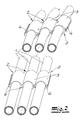
- the line network illustrated in FIG. 1 has a plurality of parallel flexible lines 1.
- the term "cables" should include cables and hoses of all kinds.
- the term especially includes energy-carrying lines, for example single- or multi-core electrical lines, fluid lines, optical cables, coaxial cables and the like.
- the lines 1 can move axially to each other in the composite.
- the line network can thereby carry out almost any movements in space while maintaining a given directional stability and always ensures an orderly, twist-free guidance of the lines.
- the cable network is just as suitable for fixed laying of cables as it is for laying cables that connect a stationary or machine-fixed connection with a movable machine part.
- the cable network is also suitable for the parallel guidance of lines on multi-axis machines and robot arms.
- the connecting elements 2 are made of plastic bodies 3, which have a line bushing fixedly connected to an associated line 1 as well as a profile 4 on the outside for connecting further connecting elements.
- the connection profile 4 is T-shaped formed as a tongue and groove and allows at a curvature of the cable network an axial displacement of the lines 1 to each other.
- FIGS. 3 to 5 are also based on the principle that the connecting elements 2 arranged or fastened to adjacent lines engage in one another in a form-fitting manner and are displaceable relative to one another in the longitudinal direction of the lines 1.
- the connecting elements 2 are integrally formed on the jacket 5 energy-carrying lines.
- the connecting elements 2 on a flexible protective tube 6, for example, a corrugated hose, integrally formed, which forms a receiving space 7 for a power line 1.
- the connecting elements 2 are integrally formed on a covering hose 8 which firmly adheres to an energy-carrying line 1.
- the coating tube 8 is, for example, a shrink tube or consists of a film which is applied with overlapping edge regions to an energy-carrying line and is closed in a tubular manner by means of a sealing seam at the overlapping edge regions.
- the cover tube 8 can also be attached by gluing on the line.
- the connecting elements 2 have a T-shaped connection profile 4 in the form of a T-shaped groove and / or a corresponding T-shaped projection or other geometries with a linear guiding function.
- the groove / spring geometries allow relative axial movements of the lines 1 to each other.
- One of the cable bushings 10 is fixedly connected to the associated line 1, while the other line 1 'rotatably and axially movable in the associated cable feedthrough 10' is arranged.
- the lines 1, 1 ' for example, an electric cable or a hose for a fluid, have a longitudinal groove 11 or a bead extending in the longitudinal direction, which cooperates as anti-rotation with a projection 12 and a groove in the associated cable feedthrough.
- the plastic body 9 is realized as a double-slip sleeve, which are formed with different inner diameters D, D 'and a projection.
- the cable bushing 10 with the smaller diameter D sits firmly with a clamping fit on the associated line 1, wherein the line is additionally secured by the engaging in the longitudinal groove 11 projection 12 against rotation.
- the line 1 ' which has a larger diameter D', the line 1 'is performed with play.
- the engaging in the longitudinal groove 11 of the line 1 'projection 12 secures the line 1' against rotation.
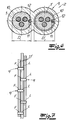
- FIG. 6 a line network of a plurality of juxtaposed lines 1, 1 'are formed. Such an arrangement is shown in FIG.
- the illustration shows how fixed connections F and loose connections L alternate on a line 1 in the longitudinal direction of the line.
Landscapes
- Engineering & Computer Science (AREA)
- General Engineering & Computer Science (AREA)
- Architecture (AREA)
- Civil Engineering (AREA)
- Structural Engineering (AREA)
- Mechanical Engineering (AREA)
- Supports For Pipes And Cables (AREA)
- Electric Cable Arrangement Between Relatively Moving Parts (AREA)
- Installation Of Indoor Wiring (AREA)
- Flexible Shafts (AREA)
- Rigid Pipes And Flexible Pipes (AREA)
- Details Of Indoor Wiring (AREA)
- Details Of Connecting Devices For Male And Female Coupling (AREA)
Abstract
Description
- Die Erfindung betrifft einen Leitungsverbund aus mindestens zwei parallelen flexiblen Leitungen, die sich im Verbund axial zueinander verschieben können. Der Begriff "Leitungen" umfasst im Rahmen der Erfindung Kabel und Schläuche aller Art. Insbesondere fallen unter den Begriff energieführende Leitungen, z. B. ein- oder mehradrige elektrische Leitungen, Fluidleitungen, Lichtleiterkabel, Koaxialkabel und dergleichen.
- Aus
DE-U 295 02 257 ist ein gewebter Leitungsverbund bekannt, in dem nebeneinander liegende Leitungen integriert sind. Der bekannte Leitungsverbund ist für eine ortsfeste Verlegung von elektrischen Leitungen bestimmt und weist eine für die Verlegung vorteilhafte hohe Biegewechselverträglichkeit und gute Verformbarkeit auf, da kein kontinuierlicher Materialfluss zwischen den Adern bzw. Leitungen besteht und sich benachbarte Leitungen im Gewebe frei gegeneinander verschieben können. Für Leitungen, die beispielsweise an einem Roboterarm oder einer Maschine einen orts- oder maschinenfesten Anschluss mit einem beweglichen Anschluss verbinden, ist der Leitungsverbund nicht geeignet, denn er weist keine ausreichende Stabilität auf, um die parallel nebeneinander verlegten Leitungen in der gewünschten Ordnung zu halten. Es besteht die Gefahr, dass die parallel verlegten Leitungen sich beim Betrieb unkontrolliert gegeneinander verdrehen. - Der Stand der Technik sieht für Leitungen, die an Roboterarmen geführt werden müssen, Energieführungsketten aus mehraxial schwenkbaren Kettengliedern vor. Energieführungsketten, die mehrachsige Bewegungen zulassen, sind in der Fertigung aufwändig und teuer. Häufig erzielt man mit solchen Energieführungsketten auch nicht den gewünschten Effekt, einerseits die Leitungen in bestimmten Bereichen richtungsstabil zu führen und gleichzeitig in anderen Bereichen die hier erforderliche Flexibilität zu gewährleisten. Ferner besteht bei diesen Ketten keine Möglichkeit, nach Ausschöpfung des vorhandenen Kettenquerschnitts zusätzliche Leitungen aufzunehmen.
- Der Erfindung liegt die Aufgabe zugrunde, einen Leitungsverbund aus parallel nebeneinander angeordneten flexiblen Leitungen anzugeben, der bogenförmige Bewegungen um alle drei Raumachsen zulässt, aber eine Verdrehung oder Verdrallung einzelner Leitungen des Verbundes um deren Längsachse sicher verhindert. Der Leitungsverbund soll nahezu beliebigen Bewegungen eines Maschinenteils folgen können und dabei stets eine parallele Ausrichtung der Leitungen gewährleisten. Der Leitungsverbund soll auch nachträglich noch durch zufügen weiterer Leitungen nahezu unbegrenzt erweiterbar sein.
- Ausgehend von einem Leitungsverbund mit den eingangs beschriebenen Merkmalen wird die Aufgabe erfindungsgemäß dadurch gelöst, dass an den Leitungen Verbindungselemente befestigt oder angeformt sind, die den Verbund zwischen den Leitungen herstellen und nur axiale Relativbewegungen zwischen benachbarten Leitungen zulassen. Der erfindungsgemäße direkte Leitungsverbund gleicht einem mehradrigen Flachkabel, bei dem jedoch die einzelnen Adern bzw. Leitungen in Leitungsrichtung jeweils gegeneinander verschiebbar sind. Die Leitungen sind ausschließlich axial zueinander verschiebbar. Durch die an den Leitungen vorgesehenen Verbindungselemente weist der Verbund gleichzeitig eine große Torsionsfähigkeit auf. Für die konstruktive Ausgestaltung ergeben sich eine Vielzahl von Möglichkeiten. So sind Konstruktionsvarianten möglich, bei denen die Verbindungselemente als Teil des Leitungsmantels oder der Schlauchwand ausgeformt sind. Unter die erfindungsgemäße Lehre fallen ferner indirekte Varianten, bei denen die Verbindungselemente als separate Teile etwa als Schrumpfschlauch, Hülse oder Schlauchschelle nachträglich befestigt werden. Unter die erfindungsgemäße Lehre fallen Intervall-Ausführungen, bei denen die Leitungen nur abschnittsweise mit Verbindungselementen versehen sind, ebenso wie Ausgestaltungen, bei denen sich die Verbindungselemente über die gesamte Leitungslänge erstrecken.
- Eine mögliche Ausgestaltung der erfindungsgemäßen Lehre sieht vor, dass die Verbindungselemente aus Kunststoffkörpern bestehen, die zwei Leitungsdurchführungen für jeweils eine Leitung aufweisen, wobei eine der Leitungsdurchführungen fest mit der zugeordneten Leitung verbindbar ist und die andere Leitung drehfest und axial beweglich in ihrer zugeordneten Leitungsdurchführung angeordnet ist. Zweckmäßig weisen die Leitungen mindestens eine Längsrille oder eine sich in Längsrichtung erstreckende Wulst auf, die als Verdrehsicherung mit einem Vorsprung bzw. einer Nut in der zugeordneten Leitungsdurchführung zusammenwirkt. Auf den Leitungen können auch Klemmringe befestigt sein, die am Außenumfang ein Profil aus Vor- und Rücksprüngen aufweisen, wobei das Profil der Klemmringe mit einem korrespondierendem Profil in den zugeordneten Leitungsdurchführungen als Verdrehsicherung zusammenwirkt.
- Eine andere Ausgestaltung der erfindungsgemäßen Lehre sieht vor, dass die an benachbarten Leitungen angeordneten oder befestigten Verbindungselemente formschlüssig ineinander greifen und in Längsrichtung der Leitungen gegeneinander verschiebbar sind. Die Verbindungselemente können aus Kunststoffkörpern bestehen, die eine mit einer zugeordneten Leitung fest verbindbarer Leitungsdurchführung sowie an den Außenseiten ein Profil zum Anschluss weiterer Verbindungselemente aufweisen.
- Das erfindungsgemäße Funktionsprinzip, dass die an benachbarten Leitungen angeordneten oder befestigten Verbindungselemente formschlüssig ineinander greifen und in Längsrichtung der Leitungen gegeneinander verschiebbar sind, lässt sich auch dadurch realisieren, dass die Verbindungselemente an dem Mantel der Leitungen einteilig angeformt sind. Die Verbindungselemente weisen zweckmäßig ein T-förmiges Anschlussprofil in Form einer T-förmigen Nut und/oder eines korrespondierenden T-förmigen Vorsprungs oder andere Geometrien mit linearer Führungsfunktion auf. Die Verbindungselemente können sich als Strangformerzeugnis über die gesamte Leitungslänge in Längsrichtung der Leitungen erstrecken. Ferner besteht die Möglichkeit, die Verbindungselemente z. B. als Kunststoffspritzgussteile in vorgegebenen Abständen an dem Kunststoffmantel der Leitungen anzubringen.
- Die Verbindungselemente können auch an einem biegsamen Schutzschlauch angeformt sein, der einen Aufnahmeraum für energieführende Leitungen bildet. Der Schutzschlauch ist beispielsweise als Wellschlauch ausgebildet, in den eine energieführende Leitung eingezogen werden kann.
- Eine weitere Ausführungsform der Erfindung sieht vor, dass die Verbindungselemente an einem Überzugsschlauch angeformt sind, der auf einer energieführenden Leitung fest haftet. Der Überzugschlauch ist als Schrumpfschlauch ausführbar oder besteht aus einer Folie, die mit überlappenden Randbereichen an den Mantel einer energieführenden Leitung angelegt und mittels einer Siegelnaht an den überlappenden Randbereichen schlauchförmig geschlossen wird.
- Im Folgenden wird die Erfindung anhand einer lediglich ein Ausführungsbeispiel darstellenden Zeichnung erläutert: Es zeigen schematisch
- Fig. 1
- eine Leitungsverbund aus mehreren parallelen Leitungen in einer perspektivischen Darstellung,
- Fig. 2
- einen Ausschnitt aus Fig. 1 in einer im Vergleich zur Fig. 1 vergrößerten Darstellung,
- Fig. 3 bis 6
- weitere Ausgestaltungen des Leitungsverbundes, jeweils im Querschnitt.
- Fig. 7
- einen Leitungsverbund aus mehreren parallelen Leitungen unter Verwendung der in Fig. 6 dargestellten Elemente.
- Der in Fig. 1 dargestellte Leitungsverbund weist mehrere parallele flexible Leitungen 1 auf. unter den Begriff "Leitungen" sollen Kabel und Schläuche aller Art fallen. Unter den Begriff fallen insbesondere energieführende Leitungen, beispielsweise ein- oder mehradrige elektrische Leitungen, Fluidleitungen, Lichtleiterkabel, Koaxialkabel und ähnliches. Die Leitungen 1 können sich im Verbund axial zueinander verschieben. Der Leitungsverbund kann dadurch unter Beibehaltung einer vorgegebenen Richtungsstabilität nahezu beliebige Bewegungen im Raum vollziehen und gewährleistet dabei immer eine geordnete, verdrallfreie Führung der Leitungen. Der Leitungsverbund ist für eine ortfeste Verlegungen von Leitungen ebenso geeignet wie zur Verlegung von Leitungen, die einen orts- oder maschinenfesten Anschluss mit einem beweglichen Maschinenteil verbinden. Insbesondere ist der Leitungsverbund auch für die Parallelführung von Leitungen an mehrachsigen Maschinen und Roboterarmen geeignet. An den Leitungen sind Verbindungselemente 2 befestigt oder angeformt, die den Verbund zwischen den Leitungen 1 herstellen und nur axiale Relativbewegungen zwischen benachbarten Leitungen zulassen. Im Ausführungsbeispiel der Fig. 2 bestehen die Verbindungselemente 2 aus Kunststoffkörpern 3, die eine mit einer zugeordneten Leitung 1 fest verbundene Leitungsdurchführung sowie an den Außenseiten ein Profil 4 zum Anschluss weiterer Verbindungselemente aufweisen. Das Anschlussprofil 4 ist T-förmig als Nut und Feder ausgebildet und erlaubt bei einer Krümmung des Leitungsverbundes eine axiale Verschiebung der Leitungen 1 zueinander.
- Auch die in den Figuren 3 bis 5 dargestellten Ausführungen beruhen auf dem Prinzip, dass die an benachbarten Leitungen angeordneten oder befestigten Verbindungselemente 2 formschlüssig ineinander greifen und in Längsrichtung der Leitungen 1 gegeneinander verschiebbar sind. In Fig. 3 sind die Verbindungselemente 2 an dem Mantel 5 energieführender Leitungen einteilig angeformt. Im Ausführungsbeispiel der Fig. 4 sind die Verbindungselemente 2 an einem biegsamen Schutzschlauch 6, beispielsweise einem Wellschlauch, angeformt, der einen Aufnahmeraum 7 für eine energieführende Leitung 1 bildet. Gemäß der Ausgestaltung in Fig. 5 sind die Verbindungselemente 2 an einem Überzugsschlauch 8 angeformt, der auf einer energieführenden Leitung 1 fest haftet. Der Überzugsschlauch 8 ist beispielsweise ein Schrumpfschlauch oder besteht aus einer Folie, die mit überlappenden Randbereichen an eine energieführenden Leitung angelegt und mittels einer Siegelnaht an den überlappenden Randbereichen schlauchförmig geschlossen wird. Der Überzugsschlauch 8 kann auch durch Kleben auf der Leitung befestigt werden. Bei allen beschriebenen Ausführungen weisen die Verbindungselemente 2 ein T-förmiges Anschlussprofil 4 in Form einer T-förmigen Nut und/oder eines korrespondierenden T-förmigen Vorsprungs oder andere Geometrien mit linearer Führungsfunktion auf. Die Nut/Federgeormetrien lassen axiale Relativbewegungen der Leitungen 1 zueinander zu.
- Im Ausführungsbeispiel der Fig. 6 bestehen die Verbindungselemente 2 aus Kunststoffkörpern 9, die zwei Leitungsdurchführungen 10, 10'für jeweils eine Leitung 1, 1' aufweisen. Eine der Leitungsdurchführungen 10 ist fest mit der zugeordneten Leitung 1 verbunden, während die andere Leitung 1' drehfest und axial beweglich in der zugeordneten Leitungsdurchführung 10' angeordnet ist. Die Leitungen 1, 1', beispielsweise ein Elektrokabel oder ein Schlauch für ein Fluid, weisen eine Längsrille 11 oder eine sich in Längsrichtung erstreckende Wulst auf, die als Verdrehsicherung mit einem Vorsprung 12 bzw. einer Nut in der zugeordneten Leitungsdurchführung zusammenwirkt. Im Ausführungsbeispiel ist der Kunststoffkörper 9 als Doppelaufsteckhülse realisiert, die mit unterschiedlichen Innendurchmessern D, D' und einem Vorsprung ausgebildet sind. Die Leitungsdurchführung 10 mit dem kleineren Durchmesser D sitzt fest mit einem Klemmsitz auf der zugeordneten Leitung 1, wobei die Leitung durch den in die Längsrille 11 eingreifenden Vorsprung 12 zusätzlich gegen Verdrehen gesichert ist. In der anderen Leitungsdurchführung 10, 10' die einen größeren Durchmesser D' aufweist, ist die Leitung 1' mit Spiel geführt. Der in die Längsrille 11 der Leitung 1' eingreifende Vorsprung 12 sichert dabei die Leitung 1' gegen Verdrehen.
- Mit den in Fig. 6 dargestellten Kunststoffkörpern 9 kann ein Leitungsverbund aus einer Mehrzahl nebeneinander liegender Leitungen 1, 1' gebildet werden. Eine solche Anordnung ist in Fig. 7 dargestellt. Der Darstellung entnimmt man, wie sich feste Verbindungen F und lose Verbindungen L auf einer Leitung 1 in Leitungslängsrichtung abwechseln.
Claims (12)
- Leitungsverbund aus mindestens zwei parallelen flexiblen Leitungen (1), die sich im Verbund axial zueinander verschieben können, dadurch gekennzeichnet, dass an den Leitungen (1) Verbindungselemente (2) befestigt oder angeformt sind, die den Verbund zwischen den Leitungen (1) herstellen und nur axiale Relativbewegungen zwischen benachbarten Leitungen (1) zulassen.
- Leitungsverbund nach Anspruch 1, dadurch gekennzeichnet, dass die Verbindungselemente aus Kunststoffkörpern (9) bestehen, die zwei Leitungsdurchführungen (10, 10') für jeweils eine Leitung (1, 1') aufweisen, wobei eine der Leitungsdurchführungen (10) fest mit der zugeordneten Leitung (1) verbindbar ist und die andere Leitung (1') drehfest und axial beweglich in ihrer zugeordneten Leitungsdurchführung (10') angeordnet ist.
- Leitungsverbund nach Anspruch 2, dadurch gekennzeichnet, dass die Leitungen (11') mindestens eine Längsrille (11) oder eine sich in Längsrichtung erstreckende Wulst aufweisen, die als Verdrehsicherung mit einem Vorsprung (12) bzw. einer Nut in der zugeordneten Leitungsdurchführung (10, 10') zusammenwirkt.
- Leitungsverbund nach Anspruch 2, dadurch gekennzeichnet, dass auf den Leitungen (1, 1') Klemmringe befestigt sind, die am Außenumfang ein Profil aus Vor- und Rücksprüngen aufweisen, und dass das Profil der Klemmringe mit einem korrespondierenden Profil in den zugeordneten Leitungsdurchführungen (10, 10') als verdrehgesicherte Linearführung zusammenwirkt.
- Leitungsverbund nach Anspruch 1, dadurch gekennzeichnet, dass die an benachbarten Leitungen (1) angeordneten oder befestigten Verbindungselemente (2) formschlüssig ineinander greifen und in Längsrichtung der Leitungen (1) gegeneinander verschiebbar sind.
- Leitungsverbund nach Anspruch 5, dadurch gekennzeichnet, dass die Verbindungselemente (2) aus Kunststoffkörpern (3) bestehen, die eine mit einer zugeordneten Leitung (1) fest verbindbare Leitungsdurchführung sowie an den Außenseiten ein Profil (4) zum Anschluss weiterer Verbindungselemente (2) aufweisen.
- Leitungsverbund nach Anspruch 5, dadurch gekennzeichnet, dass die Verbindungselemente (2) an dem Mantel (5) der Leitungen (1) einteilig angeformt sind.
- Leitungsverbund nach Anspruch 5, dadurch gekennzeichnet, dass die Verbindungselemente (2) an einem biegsamen Schutzschlauch (6) angeformt sind, der einen Aufnahmeraum für eine energieführende Leitung (1) bildet.
- Leitungsverbund nach Anspruch 5, dadurch gekennzeichnet, dass die Verbindungselemente (2) an einem Überzugsschlauch (8) angeformt sind, der auf einer energieführenden Leitung (1) fest haftet.
- Leitungsverbund nach Anspruch 9, dadurch gekennzeichnet, dass der Überzugsschlauch (8) ein Schrumpfschlauch ist.
- Leitungsverbund nach Anspruch 9, dadurch gekennzeichnet, dass der Überzugsschlauch (8) aus einer Folie besteht, die mit überlappenden Randbereichen an einer energieführenden Leitung angelegt und mittels einer Siegelnaht an den überlappenden Randbereichen schlauchförmig geschlossen wird.
- Leitungsverbund nach einem der Ansprüche 5 bis 11, dadurch gekennzeichnet, dass die Verbindungselemente (2) ein T-förmiges Anschlussprofil (4) in Form einer T-förmigen Nut und/oder eines korrespondierenden T-förmigen Vorsprungs oder andere Geometrie mit linearer Führungsfunktion aufweisen.
Priority Applications (9)
| Application Number | Priority Date | Filing Date | Title |
|---|---|---|---|
| AT07005232T ATE399282T1 (de) | 2005-04-14 | 2005-04-14 | Leitungsverbund |
| EP05008161A EP1713153B1 (de) | 2005-04-14 | 2005-04-14 | Leitungsverbund |
| AT05008161T ATE399381T1 (de) | 2005-04-14 | 2005-04-14 | Leitungsverbund |
| EP07005232A EP1793151B1 (de) | 2005-04-14 | 2005-04-14 | Leitungsverbund |
| DE502005004539T DE502005004539D1 (de) | 2005-04-14 | 2005-04-14 | Leitungsverbund |
| ES07005232T ES2306444T3 (es) | 2005-04-14 | 2005-04-14 | Acoplamiento de lineas. |
| DE502005004521T DE502005004521D1 (de) | 2005-04-14 | 2005-04-14 | Leitungsverbund |
| JP2006102921A JP2006292171A (ja) | 2005-04-14 | 2006-04-04 | 導管結合体 |
| US11/402,771 US7437052B2 (en) | 2005-04-14 | 2006-04-12 | Line combination |
Applications Claiming Priority (1)
| Application Number | Priority Date | Filing Date | Title |
|---|---|---|---|
| EP05008161A EP1713153B1 (de) | 2005-04-14 | 2005-04-14 | Leitungsverbund |
Related Child Applications (1)
| Application Number | Title | Priority Date | Filing Date |
|---|---|---|---|
| EP07005232A Division EP1793151B1 (de) | 2005-04-14 | 2005-04-14 | Leitungsverbund |
Publications (2)
| Publication Number | Publication Date |
|---|---|
| EP1713153A1 true EP1713153A1 (de) | 2006-10-18 |
| EP1713153B1 EP1713153B1 (de) | 2008-06-25 |
Family
ID=35530850
Family Applications (2)
| Application Number | Title | Priority Date | Filing Date |
|---|---|---|---|
| EP07005232A Expired - Lifetime EP1793151B1 (de) | 2005-04-14 | 2005-04-14 | Leitungsverbund |
| EP05008161A Expired - Lifetime EP1713153B1 (de) | 2005-04-14 | 2005-04-14 | Leitungsverbund |
Family Applications Before (1)
| Application Number | Title | Priority Date | Filing Date |
|---|---|---|---|
| EP07005232A Expired - Lifetime EP1793151B1 (de) | 2005-04-14 | 2005-04-14 | Leitungsverbund |
Country Status (6)
| Country | Link |
|---|---|
| US (1) | US7437052B2 (de) |
| EP (2) | EP1793151B1 (de) |
| JP (1) | JP2006292171A (de) |
| AT (2) | ATE399381T1 (de) |
| DE (2) | DE502005004521D1 (de) |
| ES (1) | ES2306444T3 (de) |
Cited By (4)
| Publication number | Priority date | Publication date | Assignee | Title |
|---|---|---|---|---|
| DE102007042067A1 (de) * | 2007-09-05 | 2009-03-26 | Zimmer Medizinsysteme Gmbh | Leitungsanordnung |
| EP2818402A1 (de) | 2013-06-28 | 2014-12-31 | Airbus Helicopters | Verbindungssystem eines Fahrzeugs, das mit einem Gurtzeug ausgestattet ist, Fahrzeug und Herstellungsverfahren |
| CN108528364A (zh) * | 2018-04-18 | 2018-09-14 | 安徽江淮汽车集团股份有限公司 | 线路固定装置 |
| CN110873250A (zh) * | 2018-09-04 | 2020-03-10 | 佛山市美的清湖净水设备有限公司 | 接头、接头组件及净水设备 |
Families Citing this family (18)
| Publication number | Priority date | Publication date | Assignee | Title |
|---|---|---|---|---|
| JP2011185376A (ja) * | 2010-03-09 | 2011-09-22 | Tigers Polymer Corp | 可撓管結束部材 |
| CN103807253B (zh) * | 2014-02-19 | 2016-08-17 | 四川上恩科技发展有限公司 | 用于燃料电池中储氢瓶位置固定的多功能卡环 |
| CA2950189C (en) * | 2014-03-12 | 2022-05-31 | Winielsen Pty Ltd | A fastener and installation device |
| WO2015143646A1 (zh) * | 2014-03-26 | 2015-10-01 | 奇点新源国际技术开发(北京)有限公司 | 光电复合缆 |
| CN103953791B (zh) * | 2014-04-24 | 2016-04-20 | 安徽正华电气有限公司 | 一种塑料电缆夹板 |
| JP7031958B2 (ja) * | 2016-12-27 | 2022-03-08 | 株式会社ディスコ | 伝達線カバーアセンブリ及び加工装置 |
| CN107294027A (zh) * | 2017-07-18 | 2017-10-24 | 国网甘肃省电力公司经济技术研究院 | 电气设备布线用支架 |
| TWM560042U (zh) * | 2017-12-29 | 2018-05-11 | 艾維克科技股份有限公司 | 管路固定裝置 |
| CN109859890B (zh) * | 2018-12-03 | 2024-05-10 | 扬州华宇电缆有限公司 | 军用智能装备用轻型高密度编织防波套 |
| DE202019103276U1 (de) * | 2019-06-11 | 2020-02-20 | Igus Gmbh | Kompakte Leitungsschutzführung für Reinraumanwendungen sowie Hülleinheit und Klemmvorrichtung hierfür |
| DE202019100169U1 (de) * | 2019-01-14 | 2020-02-20 | Igus Gmbh | Kompakte flexible Leitungsschutzführung, insbesondere für Reinraumanwendungen |
| WO2020148596A1 (de) * | 2019-01-14 | 2020-07-23 | Igus Gmbh | Kompakte leitungsschutzführung für reinraumanwendungen, sowie hülleinheit und klemmvorrichtung hierfür |
| JP6987096B2 (ja) * | 2019-03-07 | 2021-12-22 | サムウォン アクト カンパニー リミテッド | ベルト部材及びこれを含むケーブル案内装置 |
| JP7188244B2 (ja) * | 2019-04-05 | 2022-12-13 | 株式会社オートネットワーク技術研究所 | 配線部材 |
| CN111555206B (zh) * | 2020-04-24 | 2021-08-24 | 泰州市博泰电子有限公司 | 一种新能源汽车线束管夹 |
| JP7593038B2 (ja) * | 2020-10-05 | 2024-12-03 | 住友電装株式会社 | 複合ワイヤハーネス |
| JP7344253B2 (ja) * | 2021-07-13 | 2023-09-13 | 株式会社デンソーテン | 電子機器 |
| FR3151510A1 (fr) * | 2023-07-25 | 2025-01-31 | Rodrigue Peraste | Pommeau de douche double aimanté |
Citations (6)
| Publication number | Priority date | Publication date | Assignee | Title |
|---|---|---|---|---|
| US3160175A (en) * | 1961-10-02 | 1964-12-08 | Rob Ric Co | Conduit cap and spacer |
| US3420275A (en) * | 1965-03-10 | 1969-01-07 | Ideal Ind | Conduit closer and positioner |
| US3654668A (en) * | 1970-05-15 | 1972-04-11 | Arthur I Appleton | Wrapping device |
| DE8203814U1 (de) * | 1982-02-12 | 1982-08-12 | Steckermeier, Johann, 8332 Massing | Isoliertes Kabel, insbesondere elektrisches Flachkabel |
| DE4343229A1 (de) * | 1993-06-01 | 1994-12-08 | Spinner Gmbh Elektrotech | Steckverbinder für Wellrohrkoaxialkabel |
| US6061880A (en) * | 1997-05-28 | 2000-05-16 | Plastic Productions A Llc | Water supply line fastener |
Family Cites Families (5)
| Publication number | Priority date | Publication date | Assignee | Title |
|---|---|---|---|---|
| DE1449670B2 (de) * | 1962-12-03 | 1973-03-29 | Klein, Ernst, 4000 Düsseldorf | Selbsttragender energieleitungstraeger zwischen einem beweglichen verbraucher und einem ortsfesten anschluss |
| DE3333543C3 (de) * | 1983-09-16 | 1995-02-09 | Ernst Klein | Selbsttragender Energieleitungsträger |
| GB8507820D0 (en) * | 1985-03-26 | 1985-05-01 | Coal Industry Patents Ltd | Heat shield |
| DE29502257U1 (de) | 1995-02-11 | 1995-03-30 | Jährig, Mike, Dipl.-Ing., 02625 Bautzen | Leitungsverbund |
| DE19617900A1 (de) * | 1995-05-10 | 1996-12-05 | Ernst Moeckl | Kabelkette |
-
2005
- 2005-04-14 EP EP07005232A patent/EP1793151B1/de not_active Expired - Lifetime
- 2005-04-14 DE DE502005004521T patent/DE502005004521D1/de not_active Expired - Lifetime
- 2005-04-14 EP EP05008161A patent/EP1713153B1/de not_active Expired - Lifetime
- 2005-04-14 AT AT05008161T patent/ATE399381T1/de not_active IP Right Cessation
- 2005-04-14 AT AT07005232T patent/ATE399282T1/de not_active IP Right Cessation
- 2005-04-14 DE DE502005004539T patent/DE502005004539D1/de not_active Expired - Fee Related
- 2005-04-14 ES ES07005232T patent/ES2306444T3/es not_active Expired - Lifetime
-
2006
- 2006-04-04 JP JP2006102921A patent/JP2006292171A/ja active Pending
- 2006-04-12 US US11/402,771 patent/US7437052B2/en not_active Expired - Fee Related
Patent Citations (6)
| Publication number | Priority date | Publication date | Assignee | Title |
|---|---|---|---|---|
| US3160175A (en) * | 1961-10-02 | 1964-12-08 | Rob Ric Co | Conduit cap and spacer |
| US3420275A (en) * | 1965-03-10 | 1969-01-07 | Ideal Ind | Conduit closer and positioner |
| US3654668A (en) * | 1970-05-15 | 1972-04-11 | Arthur I Appleton | Wrapping device |
| DE8203814U1 (de) * | 1982-02-12 | 1982-08-12 | Steckermeier, Johann, 8332 Massing | Isoliertes Kabel, insbesondere elektrisches Flachkabel |
| DE4343229A1 (de) * | 1993-06-01 | 1994-12-08 | Spinner Gmbh Elektrotech | Steckverbinder für Wellrohrkoaxialkabel |
| US6061880A (en) * | 1997-05-28 | 2000-05-16 | Plastic Productions A Llc | Water supply line fastener |
Cited By (6)
| Publication number | Priority date | Publication date | Assignee | Title |
|---|---|---|---|---|
| DE102007042067A1 (de) * | 2007-09-05 | 2009-03-26 | Zimmer Medizinsysteme Gmbh | Leitungsanordnung |
| EP2818402A1 (de) | 2013-06-28 | 2014-12-31 | Airbus Helicopters | Verbindungssystem eines Fahrzeugs, das mit einem Gurtzeug ausgestattet ist, Fahrzeug und Herstellungsverfahren |
| FR3007899A1 (fr) * | 2013-06-28 | 2015-01-02 | Eurocopter France | Systeme de liaison d'un vehicule pourvu d'un harnais, vehicule et procede de fabrication |
| CN108528364A (zh) * | 2018-04-18 | 2018-09-14 | 安徽江淮汽车集团股份有限公司 | 线路固定装置 |
| CN108528364B (zh) * | 2018-04-18 | 2020-01-14 | 安徽江淮汽车集团股份有限公司 | 线路固定装置 |
| CN110873250A (zh) * | 2018-09-04 | 2020-03-10 | 佛山市美的清湖净水设备有限公司 | 接头、接头组件及净水设备 |
Also Published As
| Publication number | Publication date |
|---|---|
| ES2306444T3 (es) | 2008-11-01 |
| DE502005004521D1 (de) | 2008-08-07 |
| US7437052B2 (en) | 2008-10-14 |
| ATE399282T1 (de) | 2008-07-15 |
| DE502005004539D1 (de) | 2008-08-07 |
| EP1793151B1 (de) | 2008-06-25 |
| EP1793151A1 (de) | 2007-06-06 |
| ATE399381T1 (de) | 2008-07-15 |
| US20060233513A1 (en) | 2006-10-19 |
| JP2006292171A (ja) | 2006-10-26 |
| EP1713153B1 (de) | 2008-06-25 |
Similar Documents
| Publication | Publication Date | Title |
|---|---|---|
| EP1713153B1 (de) | Leitungsverbund | |
| EP1200753B1 (de) | Energiezuführungskette | |
| DE3640226C2 (de) | ||
| EP1492967B1 (de) | Roboter mit einer leitungsführungseinrichtung | |
| EP1964651B1 (de) | Roboterarm für einen Industrieroboter | |
| DE102010003282B4 (de) | Leitungsführungseinrichtung, insbesondere Energieführungskette | |
| DE102010032920A1 (de) | Räumlich auslenkbare Leitungsführungseinrichtung mit Krümmungsradiusbegrenzern | |
| EP1761982B1 (de) | Vorrichtung mit zwei relativ zueinander beweglichen teilen sowie schleppkettenanordnung | |
| DE102010039133B4 (de) | Luft- oder Raumfahrzeug mit einer Halterungsanordnung zur Halterung von Systemen | |
| DE102007041663A1 (de) | Einrichtung zum Führen von Leitungen, Schläuchen oder dergleichen | |
| EP1847745A2 (de) | Leitungsverbund | |
| DE1285035B (de) | Verfahren zum Ummanteln von Straengen, insbesondere von Kabeln | |
| DE202012011535U1 (de) | Haltevorrichtung für wenigstens eine Leitung in einem Manipulatorarm und Manipulatorarm mit einer solchen Haltevorrichtung | |
| EP0419524B1 (de) | Verfahren und vorrichtung zur kabelbaum-herstellung | |
| DE9203633U1 (de) | Freitragendes Versorgungskabel | |
| DE9014571U1 (de) | Werkzeug für die Herstellung von Kabelführungsrohren | |
| DE102016008112A1 (de) | Handhabungssystem | |
| DE102014109270B4 (de) | Leitungsfixierung, Stecker mit einer Leitungsfixierung und Verfahren zum Fixieren einer elektrischen Leitung an einem Stecker | |
| EP0979706B1 (de) | Werkzeugmaschine | |
| DE19841812C1 (de) | Stumpfschweißmaschine für Kunststoffrohre | |
| DE10125175B4 (de) | Bewegliche Führung eines flexiblen Leitungsstranges in einem Fahrzeug | |
| DE102018218363B4 (de) | Vorrichtung und Verfahren zum Auftragen einer aushärtbaren Masse | |
| DE19611586A1 (de) | Verfahren zur Herstellung einer Kabelschutzhülle und Kunststofffolie zur Durchführung des Verfahrens | |
| EP3402952B1 (de) | Kraftfahrzeugtürverschluss | |
| DE102004064009B4 (de) | Rohrverbinder |
Legal Events
| Date | Code | Title | Description |
|---|---|---|---|
| PUAI | Public reference made under article 153(3) epc to a published international application that has entered the european phase |
Free format text: ORIGINAL CODE: 0009012 |
|
| 17P | Request for examination filed |
Effective date: 20060323 |
|
| AK | Designated contracting states |
Kind code of ref document: A1 Designated state(s): AT BE BG CH CY CZ DE DK EE ES FI FR GB GR HU IE IS IT LI LT LU MC NL PL PT RO SE SI SK TR |
|
| AX | Request for extension of the european patent |
Extension state: AL BA HR LV MK YU |
|
| 17Q | First examination report despatched |
Effective date: 20061016 |
|
| 17Q | First examination report despatched |
Effective date: 20061016 |
|
| AKX | Designation fees paid |
Designated state(s): AT BE BG CH CY CZ DE DK EE ES FI FR GB GR HU IE IS IT LI LT LU MC NL PL PT RO SE SI SK TR |
|
| GRAP | Despatch of communication of intention to grant a patent |
Free format text: ORIGINAL CODE: EPIDOSNIGR1 |
|
| GRAS | Grant fee paid |
Free format text: ORIGINAL CODE: EPIDOSNIGR3 |
|
| GRAA | (expected) grant |
Free format text: ORIGINAL CODE: 0009210 |
|
| AK | Designated contracting states |
Kind code of ref document: B1 Designated state(s): AT BE BG CH CY CZ DE DK EE ES FI FR GB GR HU IE IS IT LI LT LU MC NL PL PT RO SE SI SK TR |
|
| REG | Reference to a national code |
Ref country code: GB Ref legal event code: FG4D Free format text: NOT ENGLISH |
|
| REG | Reference to a national code |
Ref country code: CH Ref legal event code: EP |
|
| REF | Corresponds to: |
Ref document number: 502005004521 Country of ref document: DE Date of ref document: 20080807 Kind code of ref document: P |
|
| REG | Reference to a national code |
Ref country code: IE Ref legal event code: FG4D Free format text: LANGUAGE OF EP DOCUMENT: GERMAN |
|
| PG25 | Lapsed in a contracting state [announced via postgrant information from national office to epo] |
Ref country code: SI Free format text: LAPSE BECAUSE OF FAILURE TO SUBMIT A TRANSLATION OF THE DESCRIPTION OR TO PAY THE FEE WITHIN THE PRESCRIBED TIME-LIMIT Effective date: 20080625 Ref country code: FI Free format text: LAPSE BECAUSE OF FAILURE TO SUBMIT A TRANSLATION OF THE DESCRIPTION OR TO PAY THE FEE WITHIN THE PRESCRIBED TIME-LIMIT Effective date: 20080625 |
|
| PG25 | Lapsed in a contracting state [announced via postgrant information from national office to epo] |
Ref country code: PL Free format text: LAPSE BECAUSE OF FAILURE TO SUBMIT A TRANSLATION OF THE DESCRIPTION OR TO PAY THE FEE WITHIN THE PRESCRIBED TIME-LIMIT Effective date: 20080625 Ref country code: NL Free format text: LAPSE BECAUSE OF FAILURE TO SUBMIT A TRANSLATION OF THE DESCRIPTION OR TO PAY THE FEE WITHIN THE PRESCRIBED TIME-LIMIT Effective date: 20080625 |
|
| NLV1 | Nl: lapsed or annulled due to failure to fulfill the requirements of art. 29p and 29m of the patents act | ||
| PG25 | Lapsed in a contracting state [announced via postgrant information from national office to epo] |
Ref country code: PT Free format text: LAPSE BECAUSE OF FAILURE TO SUBMIT A TRANSLATION OF THE DESCRIPTION OR TO PAY THE FEE WITHIN THE PRESCRIBED TIME-LIMIT Effective date: 20081125 Ref country code: LT Free format text: LAPSE BECAUSE OF FAILURE TO SUBMIT A TRANSLATION OF THE DESCRIPTION OR TO PAY THE FEE WITHIN THE PRESCRIBED TIME-LIMIT Effective date: 20080625 Ref country code: ES Free format text: LAPSE BECAUSE OF FAILURE TO SUBMIT A TRANSLATION OF THE DESCRIPTION OR TO PAY THE FEE WITHIN THE PRESCRIBED TIME-LIMIT Effective date: 20081006 Ref country code: SE Free format text: LAPSE BECAUSE OF FAILURE TO SUBMIT A TRANSLATION OF THE DESCRIPTION OR TO PAY THE FEE WITHIN THE PRESCRIBED TIME-LIMIT Effective date: 20080925 Ref country code: CZ Free format text: LAPSE BECAUSE OF FAILURE TO SUBMIT A TRANSLATION OF THE DESCRIPTION OR TO PAY THE FEE WITHIN THE PRESCRIBED TIME-LIMIT Effective date: 20080625 Ref country code: IS Free format text: LAPSE BECAUSE OF FAILURE TO SUBMIT A TRANSLATION OF THE DESCRIPTION OR TO PAY THE FEE WITHIN THE PRESCRIBED TIME-LIMIT Effective date: 20081025 |
|
| REG | Reference to a national code |
Ref country code: IE Ref legal event code: FD4D |
|
| PG25 | Lapsed in a contracting state [announced via postgrant information from national office to epo] |
Ref country code: SK Free format text: LAPSE BECAUSE OF FAILURE TO SUBMIT A TRANSLATION OF THE DESCRIPTION OR TO PAY THE FEE WITHIN THE PRESCRIBED TIME-LIMIT Effective date: 20080625 Ref country code: RO Free format text: LAPSE BECAUSE OF FAILURE TO SUBMIT A TRANSLATION OF THE DESCRIPTION OR TO PAY THE FEE WITHIN THE PRESCRIBED TIME-LIMIT Effective date: 20080625 |
|
| PG25 | Lapsed in a contracting state [announced via postgrant information from national office to epo] |
Ref country code: EE Free format text: LAPSE BECAUSE OF FAILURE TO SUBMIT A TRANSLATION OF THE DESCRIPTION OR TO PAY THE FEE WITHIN THE PRESCRIBED TIME-LIMIT Effective date: 20080625 Ref country code: BG Free format text: LAPSE BECAUSE OF FAILURE TO SUBMIT A TRANSLATION OF THE DESCRIPTION OR TO PAY THE FEE WITHIN THE PRESCRIBED TIME-LIMIT Effective date: 20080925 Ref country code: DK Free format text: LAPSE BECAUSE OF FAILURE TO SUBMIT A TRANSLATION OF THE DESCRIPTION OR TO PAY THE FEE WITHIN THE PRESCRIBED TIME-LIMIT Effective date: 20080625 Ref country code: IE Free format text: LAPSE BECAUSE OF FAILURE TO SUBMIT A TRANSLATION OF THE DESCRIPTION OR TO PAY THE FEE WITHIN THE PRESCRIBED TIME-LIMIT Effective date: 20080625 |
|
| PLBE | No opposition filed within time limit |
Free format text: ORIGINAL CODE: 0009261 |
|
| STAA | Information on the status of an ep patent application or granted ep patent |
Free format text: STATUS: NO OPPOSITION FILED WITHIN TIME LIMIT |
|
| 26N | No opposition filed |
Effective date: 20090326 |
|
| PG25 | Lapsed in a contracting state [announced via postgrant information from national office to epo] |
Ref country code: IT Free format text: LAPSE BECAUSE OF FAILURE TO SUBMIT A TRANSLATION OF THE DESCRIPTION OR TO PAY THE FEE WITHIN THE PRESCRIBED TIME-LIMIT Effective date: 20080625 |
|
| PGFP | Annual fee paid to national office [announced via postgrant information from national office to epo] |
Ref country code: FR Payment date: 20090414 Year of fee payment: 5 |
|
| BERE | Be: lapsed |
Owner name: EKD GELENKROHR G.M.B.H. Effective date: 20090430 |
|
| PGFP | Annual fee paid to national office [announced via postgrant information from national office to epo] |
Ref country code: GB Payment date: 20090421 Year of fee payment: 5 |
|
| REG | Reference to a national code |
Ref country code: CH Ref legal event code: PL |
|
| PG25 | Lapsed in a contracting state [announced via postgrant information from national office to epo] |
Ref country code: CH Free format text: LAPSE BECAUSE OF NON-PAYMENT OF DUE FEES Effective date: 20090430 Ref country code: LI Free format text: LAPSE BECAUSE OF NON-PAYMENT OF DUE FEES Effective date: 20090430 |
|
| PG25 | Lapsed in a contracting state [announced via postgrant information from national office to epo] |
Ref country code: MC Free format text: LAPSE BECAUSE OF NON-PAYMENT OF DUE FEES Effective date: 20090430 |
|
| PG25 | Lapsed in a contracting state [announced via postgrant information from national office to epo] |
Ref country code: BE Free format text: LAPSE BECAUSE OF NON-PAYMENT OF DUE FEES Effective date: 20090430 |
|
| PG25 | Lapsed in a contracting state [announced via postgrant information from national office to epo] |
Ref country code: AT Free format text: LAPSE BECAUSE OF NON-PAYMENT OF DUE FEES Effective date: 20090414 |
|
| PG25 | Lapsed in a contracting state [announced via postgrant information from national office to epo] |
Ref country code: GR Free format text: LAPSE BECAUSE OF FAILURE TO SUBMIT A TRANSLATION OF THE DESCRIPTION OR TO PAY THE FEE WITHIN THE PRESCRIBED TIME-LIMIT Effective date: 20080926 |
|
| GBPC | Gb: european patent ceased through non-payment of renewal fee |
Effective date: 20100414 |
|
| REG | Reference to a national code |
Ref country code: FR Ref legal event code: ST Effective date: 20101230 |
|
| PG25 | Lapsed in a contracting state [announced via postgrant information from national office to epo] |
Ref country code: GB Free format text: LAPSE BECAUSE OF NON-PAYMENT OF DUE FEES Effective date: 20100414 |
|
| PG25 | Lapsed in a contracting state [announced via postgrant information from national office to epo] |
Ref country code: LU Free format text: LAPSE BECAUSE OF NON-PAYMENT OF DUE FEES Effective date: 20090414 |
|
| PG25 | Lapsed in a contracting state [announced via postgrant information from national office to epo] |
Ref country code: HU Free format text: LAPSE BECAUSE OF FAILURE TO SUBMIT A TRANSLATION OF THE DESCRIPTION OR TO PAY THE FEE WITHIN THE PRESCRIBED TIME-LIMIT Effective date: 20081226 |
|
| PG25 | Lapsed in a contracting state [announced via postgrant information from national office to epo] |
Ref country code: TR Free format text: LAPSE BECAUSE OF FAILURE TO SUBMIT A TRANSLATION OF THE DESCRIPTION OR TO PAY THE FEE WITHIN THE PRESCRIBED TIME-LIMIT Effective date: 20080625 |
|
| PG25 | Lapsed in a contracting state [announced via postgrant information from national office to epo] |
Ref country code: CY Free format text: LAPSE BECAUSE OF FAILURE TO SUBMIT A TRANSLATION OF THE DESCRIPTION OR TO PAY THE FEE WITHIN THE PRESCRIBED TIME-LIMIT Effective date: 20080625 |
|
| PG25 | Lapsed in a contracting state [announced via postgrant information from national office to epo] |
Ref country code: FR Free format text: LAPSE BECAUSE OF NON-PAYMENT OF DUE FEES Effective date: 20100430 |
|
| PGFP | Annual fee paid to national office [announced via postgrant information from national office to epo] |
Ref country code: DE Payment date: 20150422 Year of fee payment: 11 |
|
| REG | Reference to a national code |
Ref country code: DE Ref legal event code: R119 Ref document number: 502005004521 Country of ref document: DE |
|
| PG25 | Lapsed in a contracting state [announced via postgrant information from national office to epo] |
Ref country code: DE Free format text: LAPSE BECAUSE OF NON-PAYMENT OF DUE FEES Effective date: 20161101 |