EP1710074A1 - Werkzeug mit einem Sensorchip und Verfahren dafür - Google Patents
Werkzeug mit einem Sensorchip und Verfahren dafür Download PDFInfo
- Publication number
- EP1710074A1 EP1710074A1 EP06014251A EP06014251A EP1710074A1 EP 1710074 A1 EP1710074 A1 EP 1710074A1 EP 06014251 A EP06014251 A EP 06014251A EP 06014251 A EP06014251 A EP 06014251A EP 1710074 A1 EP1710074 A1 EP 1710074A1
- Authority
- EP
- European Patent Office
- Prior art keywords
- tool
- packaging machine
- data
- machine
- sensor chip
- Prior art date
- Legal status (The legal status is an assumption and is not a legal conclusion. Google has not performed a legal analysis and makes no representation as to the accuracy of the status listed.)
- Granted
Links
Images


Classifications
-
- B—PERFORMING OPERATIONS; TRANSPORTING
- B26—HAND CUTTING TOOLS; CUTTING; SEVERING
- B26D—CUTTING; DETAILS COMMON TO MACHINES FOR PERFORATING, PUNCHING, CUTTING-OUT, STAMPING-OUT OR SEVERING
- B26D5/00—Arrangements for operating and controlling machines or devices for cutting, cutting-out, stamping-out, punching, perforating, or severing by means other than cutting
- B26D5/02—Means for moving the cutting member into its operative position for cutting
-
- B—PERFORMING OPERATIONS; TRANSPORTING
- B26—HAND CUTTING TOOLS; CUTTING; SEVERING
- B26D—CUTTING; DETAILS COMMON TO MACHINES FOR PERFORATING, PUNCHING, CUTTING-OUT, STAMPING-OUT OR SEVERING
- B26D5/00—Arrangements for operating and controlling machines or devices for cutting, cutting-out, stamping-out, punching, perforating, or severing by means other than cutting
-
- B—PERFORMING OPERATIONS; TRANSPORTING
- B29—WORKING OF PLASTICS; WORKING OF SUBSTANCES IN A PLASTIC STATE IN GENERAL
- B29C—SHAPING OR JOINING OF PLASTICS; SHAPING OF MATERIAL IN A PLASTIC STATE, NOT OTHERWISE PROVIDED FOR; AFTER-TREATMENT OF THE SHAPED PRODUCTS, e.g. REPAIRING
- B29C51/00—Shaping by thermoforming, i.e. shaping sheets or sheet like preforms after heating, e.g. shaping sheets in matched moulds or by deep-drawing; Apparatus therefor
- B29C51/26—Component parts, details or accessories; Auxiliary operations
- B29C51/46—Measuring, controlling or regulating
-
- B—PERFORMING OPERATIONS; TRANSPORTING
- B65—CONVEYING; PACKING; STORING; HANDLING THIN OR FILAMENTARY MATERIAL
- B65B—MACHINES, APPARATUS OR DEVICES FOR, OR METHODS OF, PACKAGING ARTICLES OR MATERIALS; UNPACKING
- B65B57/00—Automatic control, checking, warning, or safety devices
-
- B—PERFORMING OPERATIONS; TRANSPORTING
- B65—CONVEYING; PACKING; STORING; HANDLING THIN OR FILAMENTARY MATERIAL
- B65B—MACHINES, APPARATUS OR DEVICES FOR, OR METHODS OF, PACKAGING ARTICLES OR MATERIALS; UNPACKING
- B65B9/00—Enclosing successive articles, or quantities of material, e.g. liquids or semiliquids, in flat, folded, or tubular webs of flexible sheet material; Subdividing filled flexible tubes to form packages
- B65B9/02—Enclosing successive articles, or quantities of material between opposed webs
- B65B9/04—Enclosing successive articles, or quantities of material between opposed webs one or both webs being formed with pockets for the reception of the articles, or of the quantities of material
-
- B—PERFORMING OPERATIONS; TRANSPORTING
- B29—WORKING OF PLASTICS; WORKING OF SUBSTANCES IN A PLASTIC STATE IN GENERAL
- B29C—SHAPING OR JOINING OF PLASTICS; SHAPING OF MATERIAL IN A PLASTIC STATE, NOT OTHERWISE PROVIDED FOR; AFTER-TREATMENT OF THE SHAPED PRODUCTS, e.g. REPAIRING
- B29C51/00—Shaping by thermoforming, i.e. shaping sheets or sheet like preforms after heating, e.g. shaping sheets in matched moulds or by deep-drawing; Apparatus therefor
- B29C51/08—Deep drawing or matched-mould forming, i.e. using mechanical means only
-
- B—PERFORMING OPERATIONS; TRANSPORTING
- B65—CONVEYING; PACKING; STORING; HANDLING THIN OR FILAMENTARY MATERIAL
- B65B—MACHINES, APPARATUS OR DEVICES FOR, OR METHODS OF, PACKAGING ARTICLES OR MATERIALS; UNPACKING
- B65B59/00—Arrangements to enable machines to handle articles of different sizes, to produce packages of different sizes, to vary the contents of packages, to handle different types of packaging material, or to give access for cleaning or maintenance purposes
- B65B59/02—Arrangements to enable adjustments to be made while the machine is running
Definitions
- the present invention relates to a tool, in particular in a packaging machine, for deep-drawing of packaging troughs and / or seals and cutting of packages, in which the tool is raised and lowered with a lifting device.
- the present invention further includes a packaging machine having this tool and a method for automatically adjusting the machine parameters of a packaging machine.
- Packaging machines today are operable with a variety of tools.
- the machine parameters such as the bottom and top dead center of the lifting devices in the packaging machines, but also the cooling or the temperature must be reset during sealing. Since this is very expensive, attempts have been made in the past to unify the tools, such as their height, to minimize the adjustment effort. However, these tools are then not optimally designed for the particular application.
- the present invention is therefore based on the object of providing tools, in particular for packaging machines, which do not have the disadvantages of the prior art.
- a tool in particular in a packaging machine for deep-drawing of packaging troughs and / or sealing and cutting of packages, in which the tool is lifted and lowered with a lifting device, wherein the tool a sensor chip is installed, which has a descriptive and retrievable data storage having stored thereon data for identifying the tool and / or including setpoints for automatic adjustment of adjustable machine parameters.
- the tool accordingly has a writable and retrievable data memory on which data is stored.
- data may be on the one hand data such as a sequence of numbers, with a unique identifier of the tool is possible, so that an electronic device, for example a computer or a process control system, which is arranged in the packaging machine, unambiguously identifies the tool and then assigns this tool certain machine parameters and automatically adjusts them accordingly.
- the data memory already has the setpoint values for the automatic setting of the machine parameters.
- An electronic device such as a computer or process control system, reads these machine parameters from the data store and automatically adjusts them accordingly.
- These machine parameters can be, for example, the upper and the lower dead center of the lifting device, with which the respective tool is raised or lowered, the temperature to which the tool is heated or cooled, and the contact pressure with which the tool is pressed against another tool ,
- the data memory preferably contains setpoint values for the upper and particularly preferably additionally for the bottom dead center of the lifting device.
- the data memory includes identifier data with which a unique correlation and adjustment of the upper and preferably the bottom dead center of the lifting device is possible.
- the correlation data is preferably stored in a computer or process control system connected to the sensor chip.
- the two preferred embodiments of the tool according to the invention have the advantage that the height of the tool can be optimally designed. The different height is then automatically compensated by the adjustment of the top and bottom dead center of the lifting device.
- the tool according to the invention avoids long changeover times and in particular errors in the setting of machine parameters, which can lead to damage to the packaging machine and / or defective products.
- Another object of the present invention is a tool, in particular in a packaging machine, wherein in the tool, a sensor chip is installed, which has a writable and queriable data memory in which data are stored, the actual values for comparison with the data of a second, the packaging machine associated data storage are used, which are adapted to the tool data as setpoints for an actual setpoint comparison and the control of the packaging machine is designed so that it is not in operation, if the actual values of the setpoints differ.
- the tool according to the invention it is first of all ensured that its replacement by a tool not provided for the associated packaging machine is unsuccessful, because in such a case the actual setpoint comparison fails and the packaging machine can not be set in motion at all. This is true both when a non-matching tool from the same manufacturer as well as a tool from another manufacturer has been installed; in both cases, the operator is made aware of the error and a malfunction of the machine is safely avoided.
- the sensor chip is provided on the tool in a closed cavity, so that it can neither be found by unauthorized persons nor be manipulated.
- the chip is advantageously sunk in the cavity so that it, if it is discovered by accident, unusable when expanding the data storage and the sensor chip is destroyed.
- the sensor chip is attached to a tool, preferably detachably.
- the tools according to the invention can be any tools that are interchangeable in a machine, in particular a packaging machine.
- the tools are thermoforming, sealing or cutting tools.
- Data retrieval from the data memories integrated in the tools is best achieved with a packaging machine if the sensor chip is bidirectionally wirelessly coupled to a transmitting or receiving system arranged on the packaging machine or mobile. Another object of the present invention is therefore such a packaging machine.
- the transmitting and receiving system is connected via an amplifier to a second data memory and / or an electronic machine control, such as a process control system, so that the data status of the tool can be made readable and the data either to enable the commissioning of the packaging machine or automatic Adjustment of machine parameters can be used.
- the transmitting and receiving system is particularly advantageous provided in the immediate vicinity of the respective tool.
- the transmitting and receiving system can also be designed to be mobile.
- the packaging machine according to the invention has the advantage that the changeover times are minimal that when setting the process parameters no errors can happen and the pairs of tools that do not match, can not be used.
- Another object of the present invention is a method for automatically setting machine parameters using the packaging machine according to the invention, in which interrogates at least the conversion of the packaging machine, the data of the data memory at least one tool and then via the electronic control, the adjustable machine parameters according to the identifier of the tool and / or the stored setpoints are set automatically.
- the setting of the machine parameters is checked at least once via a desired-actual comparison.
- the adjustment is particularly preferably checked at regular intervals in order to ensure, in particular, a consistent quality of the products produced.
- all machine parameters that have to be set during a tool change are set automatically by the electronics of the packaging machine.
- at least the upper and lower dead center of the lifting device are automatically adapted to the tool.
- FIG. 1 shows the tool 1 according to the invention.
- the tool is a thermoforming die.
- the tool according to the invention can just as well be a sealing tool, a cutting tool or the like.
- a cavity 3 is provided, in which the sensor chip 2 is located. The cavity is closed, so that the chip is not visible from the outside and the chip is not exposed to mechanical stress.
- FIG. 2 shows a part of a packaging machine according to the invention, the thermoforming station.
- the film F1 is unrolled from a roll V1 and z. B. transported to a deep drawing station T with a chain drive. There, the film is fixed and heated with heating elements 9, wherein the heating of the film before the Thermoforming station can be done.
- the tool 1 according to the invention is located on a lifting device 5, with which it is raised and lowered. Once the tool 1 is fixed to the lifting device, the data on the sensor chip 2, which is located in the tool 1, are queried via a transmitting and receiving system. These data are then processed by a computer and this computer then controls the automatic adjustment of the machine parameters, such as the top and bottom dead center of the lifting device. Under top and bottom dead center is understood the upper or lower maximum position of the stroke.
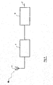
- FIG. 3 is a chemical diagram of a data acquisition and processing device according to the present invention.
- the transmitting and receiving system 4 is bidirectionally also bidirectionally connected via an amplifier 6 to a computer 7.
- This computer 7 processes the received data and forwards them via an interface 8 to the control electronics of the packaging machine, which carries out the adjustment of the machine parameters and in turn reports this position back to the computer 7.
- the computer uses a target / actual comparison to determine whether the settings are correct and then releases the machine. Similarly, the verification works, whether the tool used to the packaging machine or the counterparts is suitable.
Landscapes
- Mechanical Engineering (AREA)
- Engineering & Computer Science (AREA)
- Life Sciences & Earth Sciences (AREA)
- Forests & Forestry (AREA)
- Auxiliary Devices For And Details Of Packaging Control (AREA)
- Containers And Plastic Fillers For Packaging (AREA)
- Cutting Tools, Boring Holders, And Turrets (AREA)
- Slot Machines And Peripheral Devices (AREA)
- Measurement Of The Respiration, Hearing Ability, Form, And Blood Characteristics Of Living Organisms (AREA)
- Pinball Game Machines (AREA)
- External Artificial Organs (AREA)
- Diaphragms For Electromechanical Transducers (AREA)
- Processing Of Stones Or Stones Resemblance Materials (AREA)
- Control Of Positive-Displacement Air Blowers (AREA)
- Supply And Installment Of Electrical Components (AREA)
- Measuring Fluid Pressure (AREA)
Abstract
Description
- Die vorliegende Erfindung betrifft ein Werkzeug, insbesondere in einer Verpackungsmaschine, zum Tiefziehen von Verpackungsmulden und/oder Siegeln und Schneiden von Verpackungen, bei der das Werkzeug mit einer Hubvorrichtung angehoben und abgesenkt wird. Die vorliegende Erfindung beinhaltet des weiteren eine Verpackungsmaschine, die dieses Werkzeug aufweist und ein Verfahren zum automatischen Einstellen der Maschinenparameter einer Verpackungsmaschine.
- Verpackungsmaschinen sind heutzutage mit einer Vielzahl von Werkzeugen betreibbar. Bei einem Wechsel dieser Werkzeuge müssen die Maschinenparameter, wie beispielsweise der untere und obere Totpunkt der Hubvorrichtungen in den Verpackungsmaschinen, aber auch die Kühlung bzw. die Temperatur beim Siegeln neu eingestellt werden. Da dies sehr aufwendig ist, hat man in der Vergangenheit versucht, die Werkzeuge, beispielsweise deren Bauhöhe, zu vereinheitlichen, um den Einstellaufwand zu minimieren. Diese Werkzeuge sind dann jedoch für den jeweiligen Anwendungsfall nicht optimal gestaltet.
- Der vorliegenden Erfindung liegt deshalb die Aufgabe zugrunde, Werkzeuge, insbesondere für Verpackungsmaschinen, zur Verfügung zu stellen, die die Nachteile des Standes der Technik nicht aufweisen.
- Gelöst wird diese Aufgabe durch ein Werkzeug, insbesondere in einer Verpackungsmaschine zum Tiefziehen von Verpackungsmulden und/oder Siegeln und Schneiden von Verpackungen, bei der das Werkzeug mit einer Hubvorrichtung angehoben und abgesenkt wird, wobei in das Werkzeug ein Sensorchip eingebaut ist, der einen beschreib- und abfragbaren Datenspeicher aufweist, auf dem Daten gespeichert sind, die zur Kennung des Werkzeuges dienen und/oder Sollwerte für die automatische Einstellung von verstellbaren Maschinenparametern beinhalten.
- Erfindungsgemäß weist das Werkzeug demnach einen beschreib- und abfragbaren Datenspeicher auf, auf dem Daten gespeichert sind. Diese Daten können zum einen Daten wie beispielsweise eine Zahlenfolge sein, mit der eine eindeutige Kennung des Werkzeuges möglich ist, so daß eine elektronische Vorrichtung, beispielsweise ein Computer oder ein Prozeßleistsystem, die in der Verpackungsmaschine angeordnet ist, zweifelsfrei das Werkzeug identifiziert und dann diesem Werkzeug bestimmte Maschinenparameter zuordnet und diese automatisch entsprechend einstellt.
- Ebenfalls erfindungsgemäß weist der Datenspeicher bereits die Sollwerte für die automatische Einstellung der Maschinenparameter auf. Eine elektronische Vorrichtung, beispielsweise ein Computer oder ein Prozeßteitsystem, lesen diese Maschinenparameter von dem Datenspeicher und stellen sie automatisch entsprechend ein.
- Diese Maschinenparameter können beispielsweise der obere und der untere Totpunkt der Hubvorrichtung, mit der das jeweilige Werkzeug angehoben bzw. abgesenkt wird, die Temperatur auf die das Werkzeug erwärmt oder gekühlt wird sowie der Anpreßdruck, mit dem das Werkzeug gegen ein anderes Werkzeug gedrückt wird, sein.
- Vorzugsweise beinhaltet der Datenspeicher Sollwerte für den oberen und besonders bevorzugt zusätzlich für den unteren Totpunkt der Hubvorrichtung.
- In einer anderen bevorzugten Ausführungsform beinhaltet der Datenspeicher Kennungsdaten, mit denen eine eindeutige Korrelierung und Einstellung des oberen und vorzugsweise des unteren Totpunktes der Hubvorrichtung möglich ist. Die Korrelationsdaten sind vorzugsweise in einen Computer oder einem Prozeßleitsystem gespeichert, der/das mit dem Sensorchip verbunden ist.
- Diese beiden bevorzugten Ausführungsformen des erfindungsgemäßen Werkzeuges haben den Vorteil, daß die Höhe des Werkzeuges optimal gestaltet werden kann. Die unterschiedliche Höhe wird dann automatisch durch die Einstellung des oberen und des unteren Totpunktes der Hubvorrichtung kompensiert. Durch das erfindungsgemäße Werkzeug werden lange Umrüstzeiten und insbesondere Fehler bei der Einstellung von Maschinenparametern, die zu einer Beschädigung der Verpackungsmaschine und/oder mangelhaften Produkten führen kann, vermieden.
- Ein weiterer Gegenstand der vorliegenden Erfindung ist ein Werkzeug, insbesondere in einer Verpackungsmaschine, wobei in das Werkzeug ein Sensorchip eingebaut ist, der ein beschreib- und abfragbaren Datenspeicher aufweist, in dem Daten gespeichert sind, die als Ist-Werte zum Abgleich mit den Daten eines zweiten, der Verpackungsmaschine zugeordneten Datenspeichers verwendet werden, dessen auf das Werkzeug abgestimmte Daten als Sollwerte für einen Ist-Sollwert-Vergleich dienen und die Steuerung der Verpackungsmaschine so ausgelegt ist, daß diese nicht in Betrieb nehmbar ist, wenn die Ist-Werte von den Sollwerten abweichen.
- Bei dem erfindungsgemäßen Werkzeug ist zunächst einmal sichergestellt, daß dessen Ersatz durch ein für die zugehörige Verpackungsmaschine nicht vorgesehenes Werkzeug nicht gelingt, weil in einem solchen Fall der Ist-Sollwert-Vergleich mißlingt und die Verpackungsmaschine überhaupt nicht in Gang setzbar ist. Das trifft sowohl dann zu, wenn ein nicht passendes Werkzeug desselben Herstellers als auch ein Werkzeug eines anderen Herstellers eingebaut worden ist; in beiden Fällen wird der Betreiber auf den Fehler aufmerksam gemacht und eine Fehlfunktion der Maschine wird sicher vermieden.
- Zusätzlich ist es nunmehr möglich, daß auch bei solchen Verpackungsmaschinen, bei dem außer dem Werkzeug auch das dazugehörige Gegenstück, beispielsweise der Stempel beim Tiefziehen und/oder das Oberwerkzeug beim Siegeln auswechselbar ist, gewährleistet werden kann, daß nur eine solche Paarung ausgebildet werden kann, bei der die einzelnen Werkzeuge zueinander passend sind. Ist dies nicht der Fall, verhindert die Steuerung der Verpackungsmaschine wiederum deren Inbetriebnahme.
- Bei den beiden o. g. Gegenständen der vorliegenden Erfindung ist es besonders vorteilhaft, wenn der Sensorchip an dem Werkzeug in einem abgeschlossenen Hohlraum vorgesehen ist, so daß er für Unbefugte weder auffindbar ist, noch manipuliert werden kann. Der Chip wird vorteilhafterweise so in dem Hohlraum versenkt, daß er, wenn er zufällig entdeckt wird, beim Ausbau der Datenspeicher unbrauchbar und der Sensorchip zerstört wird. Ebenfalls bevorzugt wird der Sensorchip an einem Werkzeug, vorzugsweise lösbar befestigt.
- Die erfindungsgemäßen Werkzeuge können jegliche Werkzeuge sein, die bei einer Maschine, insbesondere einer Verpackungsmaschine auswechselbar sind. Vorzugsweise sind die Werkzeuge jedoch Tiefzieh-, Siegel- oder Schneidwerkzeuge.
- Die Datenabfrage aus den in den Werkzeugen integrierten Datenspeichern gelingt bei einer Verpackungsmaschine am besten, wenn der Sensorchip mit einer an der Verpackungsmaschine angeordneten oder mobilen Sende- und Empfangsanlage bidirektional drahtlos gekoppelt ist. Ein weiteren Gegenstand der vorliegenden Erfindung ist deshalb eine solche Verpackungsmaschine.
- Vorzugsweise ist die Sende- und Empfangsanlage über einen Verstärker mit einem zweiten Datenspeicher und/oder einer elektronischen Maschinensteuerung, beispielsweise einem Prozeßleitsystem, verbunden, so daß der Datenstand des Werkzeug ablesbar gemacht werden kann und die Daten entweder zur Freigabe der Inbetriebnahme der Verpackungsmaschine oder zur automatischen Einstellung von Maschinenparametern herangezogen werden können. Die Sende- und Empfangsanlage ist besonders vorteilhaft in unmittelbarer Nähe des jeweiligen Werkzeuges vorgesehen.
- Vorteilhaft kann die Sende- und Empfangsanlage auch mobil ausgebildet sein.
- Die erfindungsgemäße Verpackungsmaschine hat den Vorteil, daß die Umrüstzeiten minimal sind, daß bei der Einstellung der Verfahrensparameter keine Fehler passieren können und das Werkzeugpaare, die nicht zusammenpassen, nicht eingesetzt werden können.
- Ein weiterer Gegenstand der vorliegenden Erfindung ist ein Verfahren zum automatischen Einstellen von Maschinenparametern unter Verwendung der erfindungsgemäßen Verpackungsmaschine, bei dem zumindest beim Umrüsten der Verpackungsmaschine die Daten des Datenspeichers mindestens eines Werkzeuges abgefragt und dann über die elektronische Steuerung die einstellbaren Maschinenparameter entsprechend der Kennung des Werkzeuges und/oder den gespeicherten Sollwerten automatisch eingestellt werden.
- In einer vorteilhaften Ausführungsform der vorliegenden Erfindung wird über einen Soll-Ist-Vergleich die Einstellung der Maschinenparameter zumindest einmal überprüft. Besonders bevorzugt wird die Einstellung jedoch in regelmäßigen Abständen überprüft, um insbesondere eine gleichbleibende Qualität der hergestellten Produkte sicherzustellen.
- Vorzugsweise werden alle Maschinenparameter, die bei einem Werkzeugwechsel eingestellt werden müssen, von der Elektronik der Verpackungsmaschine automatisch eingestellt. Besonders bevorzugt werden jedoch zumindest der obere und der untere Totpunkt der Hubvorrichtung automatisch an das Werkzeug angepaßt.
- Im folgenden wird die Erfindung anhand der Figuren 1 bis 3 erläutert. Diese Erläuterungen sind lediglich beispielhaft und schränken den allgemeinen Erfindungsgedanken nicht ein.
- Figur 1 zeigt ein erfindungsgemäßes Werkzeug.
- Figur 2 zeigt die erfindungsgemäße Verpackungsmaschine.
- Figur 3 zeigt die Empfangs- und Verstärkeranlage.
- In Figur 1 ist das erfindungsgemäße Werkzeug 1 dargestellt. In dem vorliegenden Beispiel ist das Werkzeug eine Tiefziehmatrize. Der Fachmann erkennt, daß das erfindungsgemäße Werkzeug genauso gut ein Siegelwerkzeug, ein Schneidwerkzeug oder dergleichen sein kann. In dem Werkzeug 1 ist ein Hohlraum 3 vorgesehen, in dem sich der Sensorchip 2 befindet. Der Hohlraum ist abgeschlossen, so daß der Chip von außen nicht sichtbar ist und der Chip keinen mechanischen Belastungen ausgesetzt ist.
- In Figur 2 ist ein Teil einer erfindungsgemäßen Verpackungsmaschine, die Tiefziehstation, dargestellt. Die Folie F1 wird von einer Rolle V1 abgerollt und z. B. mit einem Kettenantrieb zur Tiefziehstation T transportiert. Dort wird die Folie fixiert und mit Heizelementen 9 erwärmt, wobei das Erwärmen der Folie auch vor der Tiefziehstation erfolgen kann. Das erfindungsgemäße Werkzeug 1 befindet sich auf einer Hubvorrichtung 5, mit der es angehoben und abgesenkt wird. Sobald das Werkzeug 1 an der Hubvorrichtung fixiert wird, werden über eine Sende- und Empfangsanlage die Daten auf dem Sensorchip 2, der sich in dem Werkzeug 1 befindet, abgefragt. Diese Daten werden sodann mit einem Computer verarbeitet und dieser Computer steuert sodann die automatische Einstellung der Maschinenparameter, wie beispielsweise des oberen und unteren Totpunktes der Hubvorrichtung. Unter oberem und unterem Totpunkt wird die obere bzw. untere Maximalstellung des Hubes verstanden.
- Figur 3 ist eine chematische Darstellung einer Einrichtung zur Datenerfassung und Verarbeitung gemäß der vorliegenden Erfindung dargestellt. Die Sende- und Empfangsanlage 4 ist bidirektional über einen Verstärker 6 mit einem Computer 7 ebenfalls bidirektional verbunden. Dieser Computer 7 verarbeitet die empfangenen Daten und leitet diese über ein Interface 8 an die Steuerelektronik der Verpackungsmaschine weiter, die die Einstellung der Maschinenparameter vornimmt und diese Stellung wiederum an den Computer 7 zurückmeldet. Der Computer ermittelt über einen Soll-Ist-Vergleich, ob die Einstellungen richtig sind und gibt erst dann die Maschine frei. Analog funktioniert auch die Überprüfung, ob das eingesetzte Werkzeug zu der Verpackungsmaschine bzw. den Gegenstücken passend ist.
Claims (13)
- Werkzeug (1), insbesondere in einer Verpackungsmaschine zum Tiefziehen von Verpackungsmulden und/oder Siegeln und Schneiden von Verpackungen, bei der das Werkzeug mit einer Hubvorrichtung (5) angehoben und abgesenkt wird, dadurch gekennzeichnet, daß in das Werkzeug ein Sensor-Chip (2) eingebaut ist, der einen beschreib- und abfragbaren Datenspeicher aufweist, auf dem Daten gespeichert sind, die zur Kennung des Werkzeuges dienen und/oder Sollwerte für die automatische Einstellung von verstellbaren Maschinenparametern beinhalten.
- Werkzeug nach Anspruch 1, dadurch gekennzeichnet, daß als Sollwert der obere und vorzugsweise des untere Totpunktes der Hubvorrichtung gespeichert ist.
- Werkzeug nach Anspruch 1, dadurch gekennzeichnet, daß anhand der Kennung in dem Datenspeicher der obere und vorzugsweise der untere Totpunktes der Hubvorrichtung korrelierbar ist.
- Werkzeug, insbesondere in einer Verpackungsmaschine, dadurch gekennzeichnet, daß in das Werkzeug ein Sensor-Chip (2) eingebaut ist, der einen beschreib- und abfragbaren Datenspeicher aufweist, in dem Daten gespeichert sind, die als Ist-Werte zum Abgleich mit den Daten eines zweiten, der Verpackungsmaschine zugeordneten Datenspeichers verwendet werden, dessen auf das Werkzeug abgestimmte Daten als Sollwert für einen Istwert-Sollwert-Vergleich dienen, wobei die Steuerung der Verpackungsmaschine so ausgelegt ist, daß diese nicht in Betrieb nehmbar ist, wenn die Ist-Werte von den Sollwerten abweichen.
- Werkzeug nach einem der Ansprüche 1-4, dadurch gekennzeichnet, daß der Sensor-Chip in einem abgeschlossenen Hohlraum vorgesehen ist oder außen am Werkzeug angebracht ist.
- Werkzeug nach einem der Ansprüche 1-5, dadurch gekennzeichnet, daß es ein Tiefzieh-, Siegel- oder Schneidwerkzeug ist.
- Verpackungsmaschine mit mindestens einem Werkzeug gemäß einem der Ansprüche 1-6, dadurch gekennzeichnet, daß der Sensor-Chip mit einer an der Verpackungsmaschine angeordneten oder mobilen Sende- und Empfangsanlage (4) bidirektional drahtlos gekoppelt ist.
- Verpackungsmaschine nach Anspruch 7, dadurch gekennzeichnet, daß die Sende- und Empfangsanlage (4) über einen Verstärker (6) mit dem zweiten Datenspeicher und/oder einer elektronischen Maschinensteuerung verbunden ist.
- Verpackungsmaschine nach Anspruch 7 oder 8, dadurch gekennzeichnet, daß sie nur dann in Betrieb nehmbar ist, wenn die Ist-Werte mit den Soll-Werten übereinstimmen.
- Verpackungsmaschine nach einem der Ansprüche 7-9, dadurch gekennzeichnet, daß eine elektronische Steuerung aufgrund der Kennung des Werkzeuges automatisch gewisse Maschinenparameter einstellt.
- Verfahren zum automatischen Einstellen von Maschinenparametern unter Verwendung der Verpackungsmaschine gemäß einem der Patentansprüche 7-10, dadurch gekennzeichnet, daß zumindest beim Umrüsten der Verpackungsmaschine die Daten des Datenspeichers des Werkzeuges (1) abgefragt werden und dann über eine elektronische Steuerung die einstellbaren Maschinenparametern entsprechend der Kennung und/oder den Sollwerten automatisch eingestellt werden.
- Verfahren nach Anspruch 11, dadurch gekennzeichnet, daß über einen Soll-Ist-Vergleich die Einstellung der Maschinenparameter mindestens einmal überprüft wird.
- Verfahren nach Anspruch 11 oder 12, dadurch gekennzeichnet, daß die einzustellenden Maschinenparameter zumindest der obere und der untere Totpunkt der Hubvorrichtung sind.
Applications Claiming Priority (2)
| Application Number | Priority Date | Filing Date | Title |
|---|---|---|---|
| DE10129392A DE10129392A1 (de) | 2001-06-20 | 2001-06-20 | Werkzeug mit einem Sensorchip |
| EP02762294A EP1401632B1 (de) | 2001-06-20 | 2002-06-19 | Verfahren zum automatischen Einstellen von Maschinenparametern |
Related Parent Applications (1)
| Application Number | Title | Priority Date | Filing Date |
|---|---|---|---|
| EP02762294A Division EP1401632B1 (de) | 2001-06-20 | 2002-06-19 | Verfahren zum automatischen Einstellen von Maschinenparametern |
Publications (3)
| Publication Number | Publication Date |
|---|---|
| EP1710074A1 true EP1710074A1 (de) | 2006-10-11 |
| EP1710074B1 EP1710074B1 (de) | 2014-10-08 |
| EP1710074B8 EP1710074B8 (de) | 2014-11-19 |
Family
ID=7688597
Family Applications (2)
| Application Number | Title | Priority Date | Filing Date |
|---|---|---|---|
| EP06014251.0A Expired - Lifetime EP1710074B8 (de) | 2001-06-20 | 2002-06-19 | Werkzeug mit einem Sensorchip |
| EP02762294A Expired - Lifetime EP1401632B1 (de) | 2001-06-20 | 2002-06-19 | Verfahren zum automatischen Einstellen von Maschinenparametern |
Family Applications After (1)
| Application Number | Title | Priority Date | Filing Date |
|---|---|---|---|
| EP02762294A Expired - Lifetime EP1401632B1 (de) | 2001-06-20 | 2002-06-19 | Verfahren zum automatischen Einstellen von Maschinenparametern |
Country Status (9)
| Country | Link |
|---|---|
| US (2) | US7010898B2 (de) |
| EP (2) | EP1710074B8 (de) |
| CN (1) | CN1518493A (de) |
| AT (1) | ATE344127T1 (de) |
| DE (2) | DE10129392A1 (de) |
| DK (1) | DK1401632T3 (de) |
| ES (2) | ES2526808T3 (de) |
| NO (1) | NO20035614D0 (de) |
| WO (1) | WO2003000481A1 (de) |
Cited By (1)
| Publication number | Priority date | Publication date | Assignee | Title |
|---|---|---|---|---|
| WO2017021554A1 (de) | 2015-08-06 | 2017-02-09 | Multivac Sepp Haggenmüller Se & Co. Kg | Selbststeuernde verpackungsmaschine und verfahren dafür |
Families Citing this family (20)
| Publication number | Priority date | Publication date | Assignee | Title |
|---|---|---|---|---|
| DE10359479A1 (de) * | 2003-12-17 | 2005-07-21 | Cfs Germany Gmbh | Längsschneider |
| KR100836968B1 (ko) * | 2003-12-24 | 2008-06-10 | 몰렉스 인코포레이티드 | 변형 임피던스 및 납땜 랜드를 구비한 전송 라인 |
| DE102004045783B4 (de) * | 2004-09-21 | 2019-09-12 | Peter Schöberl | Thermoformwerkzeug |
| DE102005006783B4 (de) * | 2005-02-14 | 2006-10-12 | Uhlmann Pac-Systeme Gmbh & Co Kg | Arbeitsstation |
| RU2421464C2 (ru) | 2005-10-21 | 2011-06-20 | Новартис Аг | Человеческие антитела к il-13 и их терапевтическое применение |
| DE102005059312C5 (de) * | 2005-12-09 | 2019-11-28 | Multivac Sepp Haggenmüller Se & Co. Kg | Verpackungsmaschine |
| DE102007062983A1 (de) * | 2007-12-21 | 2009-06-25 | Ulma Packaging Gmbh | Verpackungsmaschine |
| US8883054B2 (en) | 2009-06-18 | 2014-11-11 | Progressive Components International Corporation | Mold monitoring |
| CN105313270B (zh) * | 2009-06-18 | 2017-09-15 | 博革新元件国际公司 | 保存模具周期计数的监视器及检索模具周期数据的方法 |
| DE102009044163A1 (de) * | 2009-10-01 | 2011-04-07 | Krones Ag | Verfahren zum Auswechseln von Werkzeugen bei einem Verpackungs- und Lagersystem, Computerprogramm hierzu und Verpackungs- und Lagersystem |
| DE102010009536A1 (de) * | 2010-02-26 | 2011-09-01 | Cfs Germany Gmbh | Verfahren zum Wechsel des Ober- und Unterwerkzeugs einer Verpackungsmaschine |
| SMT201900299T1 (it) * | 2010-11-10 | 2019-07-11 | Dellcron Innovation Ab | Metodo per posizionare almeno un condotto/cavo di comunicazione sotto una superficie stradale in un'area |
| WO2013055801A1 (en) | 2011-10-10 | 2013-04-18 | Glenn Starkey | System and method for monitoring tooling activities |
| EP2586590A1 (de) * | 2011-10-29 | 2013-05-01 | Gabler Thermoform GmbH & Co. KG | Verfahren zum Betreiben einer Thermoformmaschine und Thermoformmaschine |
| DE102012003830A1 (de) * | 2012-02-29 | 2013-08-29 | Gea Cfs Germany Gmbh | Verpackungsmaschine mit einem auswechselbaren Werkzeug |
| ITMO20140338A1 (it) * | 2014-11-19 | 2016-05-19 | Paolo Antonini | Stampo per la formatura di manufatti, semilavorati, o simili |
| DE102016216794A1 (de) * | 2015-09-29 | 2017-03-30 | Robert Bosch Gmbh | Handwerkzeugmaschine mit mindestens einem maschinenseitigem Kontaktelement |
| DE102018215913A1 (de) * | 2018-09-19 | 2020-03-19 | Multivac Sepp Haggenmüller Se & Co. Kg | Verpackungsmaschine mit automatischer Komponentenerkennung |
| DE102022115714A1 (de) | 2022-06-23 | 2023-12-28 | Multivac Sepp Haggenmüller Se & Co. Kg | Siegelvorrichtung mit Kühleinrichtung sowie Verfahren zum Kühlen eines Trays |
| DE102022122909B3 (de) | 2022-09-09 | 2023-09-21 | Multivac Sepp Haggenmüller Se & Co. Kg | Lebensmittelverarbeitungsmaschine und Verfahren zum Einschränken von durch einen Bediener an einer Lebensmittelverarbeitungsmaschine aktivierbaren Prozessen |
Citations (6)
| Publication number | Priority date | Publication date | Assignee | Title |
|---|---|---|---|---|
| JPS61252114A (ja) * | 1985-05-02 | 1986-11-10 | Japan Steel Works Ltd:The | 金型自動確認方法 |
| JPH07161745A (ja) * | 1993-12-02 | 1995-06-23 | Hitachi Ltd | 樹脂封止型半導体装置用トランスファモールド装置 |
| US5571539A (en) * | 1994-12-30 | 1996-11-05 | D & L Incorporated | Mold with an on-board counter or monitor |
| US6047579A (en) * | 1998-04-17 | 2000-04-11 | The Minster Machine Company | RF tag attached to die assembly for use in press machine |
| JP2000281361A (ja) * | 1999-03-29 | 2000-10-10 | Fuji Photo Optical Co Ltd | 光学部品成形装置、及び光学部品成形方法 |
| EP1084806A2 (de) * | 1999-09-17 | 2001-03-21 | Woschnik + Partner Maschinenbau GmbH | Identifikationssystem für die Stanzwerkzeuge einer Flachbett-Stanze |
Family Cites Families (27)
| Publication number | Priority date | Publication date | Assignee | Title |
|---|---|---|---|---|
| US4014275A (en) * | 1975-11-13 | 1977-03-29 | The Singer Company | Sewing machine re-programmable memory |
| DE3326615A1 (de) * | 1983-07-23 | 1985-01-31 | Otto Bilz, Werkzeugfabrik, 7302 Ostfildern | Werkzeug oder werkzeughalter, insbesondere fuer die zerspanende bearbeitung auf numerisch gesteuerten bearbeitungszentren |
| JPS62120945A (ja) * | 1985-11-20 | 1987-06-02 | Tokyo Keiki Co Ltd | 工具ホルダ |
| DE3541676A1 (de) * | 1985-11-26 | 1987-05-27 | Euchner & Co | Identifikationssystem |
| US4742470A (en) * | 1985-12-30 | 1988-05-03 | Gte Valeron Corporation | Tool identification system |
| US4850766A (en) * | 1987-01-09 | 1989-07-25 | Yamazaki Mazaki Corporation | Pull stud |
| US4927299A (en) * | 1987-05-21 | 1990-05-22 | Regents Of The University Of Minnesota | Integral acoustic emission sensor for manufacturing processes and mechanical components |
| US5254023A (en) * | 1989-03-08 | 1993-10-19 | Yamaha Hatsudoki Kabushiki Kaisha | Water jet propulsion unit |
| JPH03106600A (ja) * | 1989-09-20 | 1991-05-07 | Teijin Seiki Co Ltd | プレス機械 |
| US5047579A (en) * | 1990-01-26 | 1991-09-10 | Monsanto Company | Process for producing n-phosphonomethylglycine |
| US5111004A (en) * | 1991-05-23 | 1992-05-05 | Kumahira Safe Co., Inc. | Stylus for handwriting identification |
| JPH0729223B2 (ja) * | 1991-06-28 | 1995-04-05 | アイダエンジニアリング株式会社 | プレス機械の下死点位置補正装置 |
| US5419169A (en) * | 1992-04-07 | 1995-05-30 | Toyota Jidosha Kabushiki Kaisha | Method and apparatus for adjusting press operating conditions depending upon dies used |
| JP3172609B2 (ja) * | 1992-11-28 | 2001-06-04 | アピックヤマダ株式会社 | 金型装置 |
| JP3518883B2 (ja) * | 1993-10-19 | 2004-04-12 | 株式会社小松製作所 | パンチプレス機における金型管理方法 |
| ES2187540T3 (es) * | 1994-12-30 | 2003-06-16 | Progressive Components Interna | Molde con contador incorporado. |
| US5661656A (en) * | 1995-05-26 | 1997-08-26 | Breed Technologies, Inc. | Method and apparatus for improved tool set-up and adjustment using thin tactile sensors |
| ES2196202T3 (es) * | 1996-02-02 | 2003-12-16 | Georg Taubmann | Procedimiento y dispositivo para la gestion de moldes para la produccion mecanica de cuerpos moldeados de hormigon o de materiales similares. |
| US5622069A (en) * | 1996-03-11 | 1997-04-22 | Oberg Industries, Inc. | Stamping die with attached plc |
| JP4201094B2 (ja) * | 1997-12-26 | 2008-12-24 | 村田機械株式会社 | プレス機械 |
| DE19824588A1 (de) * | 1998-06-02 | 1999-12-09 | Kraemer & Grebe Kg | Matrize und Verfahren zur Herstellung einer Verpackungsmulde mit Hinterschnitt |
| US6411863B1 (en) * | 1998-11-02 | 2002-06-25 | The Minster Machine Company | Auxiliary control system for use with programmable logic controller in a press machine |
| US6101857A (en) * | 1999-04-06 | 2000-08-15 | Oberg Industries | Apparatus for monitoring and controlling progressive punch press production of articles and associated method |
| DE19925458C2 (de) | 1999-06-02 | 2002-07-18 | Fraunhofer Ges Forschung | Herstellungsverfahren für Umform-, Stanz- und Spritzgußwerkzeuge |
| DE10029133A1 (de) * | 2000-06-14 | 2002-01-03 | Hilti Ag | Elektrohandwerkzeuggerät mit Werkzeug |
| US6456898B1 (en) * | 2000-09-05 | 2002-09-24 | Rockwell Automation Technologies, Inc. | Press monitoring and control system |
| US6585628B1 (en) * | 2001-05-22 | 2003-07-01 | Dana Corporation | Cutter tool assembly and system |
-
2001
- 2001-06-20 DE DE10129392A patent/DE10129392A1/de not_active Withdrawn
-
2002
- 2002-06-19 WO PCT/EP2002/006781 patent/WO2003000481A1/de not_active Ceased
- 2002-06-19 DE DE50208603T patent/DE50208603D1/de not_active Expired - Lifetime
- 2002-06-19 AT AT02762294T patent/ATE344127T1/de active
- 2002-06-19 EP EP06014251.0A patent/EP1710074B8/de not_active Expired - Lifetime
- 2002-06-19 ES ES06014251.0T patent/ES2526808T3/es not_active Expired - Lifetime
- 2002-06-19 US US10/481,355 patent/US7010898B2/en not_active Expired - Lifetime
- 2002-06-19 ES ES02762294T patent/ES2278950T3/es not_active Expired - Lifetime
- 2002-06-19 EP EP02762294A patent/EP1401632B1/de not_active Expired - Lifetime
- 2002-06-19 DK DK02762294T patent/DK1401632T3/da active
- 2002-06-19 CN CNA028122739A patent/CN1518493A/zh active Pending
-
2003
- 2003-12-16 NO NO20035614A patent/NO20035614D0/no not_active Application Discontinuation
-
2006
- 2006-01-05 US US11/326,602 patent/US20060156690A1/en not_active Abandoned
Patent Citations (6)
| Publication number | Priority date | Publication date | Assignee | Title |
|---|---|---|---|---|
| JPS61252114A (ja) * | 1985-05-02 | 1986-11-10 | Japan Steel Works Ltd:The | 金型自動確認方法 |
| JPH07161745A (ja) * | 1993-12-02 | 1995-06-23 | Hitachi Ltd | 樹脂封止型半導体装置用トランスファモールド装置 |
| US5571539A (en) * | 1994-12-30 | 1996-11-05 | D & L Incorporated | Mold with an on-board counter or monitor |
| US6047579A (en) * | 1998-04-17 | 2000-04-11 | The Minster Machine Company | RF tag attached to die assembly for use in press machine |
| JP2000281361A (ja) * | 1999-03-29 | 2000-10-10 | Fuji Photo Optical Co Ltd | 光学部品成形装置、及び光学部品成形方法 |
| EP1084806A2 (de) * | 1999-09-17 | 2001-03-21 | Woschnik + Partner Maschinenbau GmbH | Identifikationssystem für die Stanzwerkzeuge einer Flachbett-Stanze |
Non-Patent Citations (3)
| Title |
|---|
| PATENT ABSTRACTS OF JAPAN vol. 011, no. 102 (M - 576) 31 March 1987 (1987-03-31) * |
| PATENT ABSTRACTS OF JAPAN vol. 1995, no. 09 31 October 1995 (1995-10-31) * |
| PATENT ABSTRACTS OF JAPAN vol. 2000, no. 13 5 February 2001 (2001-02-05) * |
Cited By (6)
| Publication number | Priority date | Publication date | Assignee | Title |
|---|---|---|---|---|
| WO2017021554A1 (de) | 2015-08-06 | 2017-02-09 | Multivac Sepp Haggenmüller Se & Co. Kg | Selbststeuernde verpackungsmaschine und verfahren dafür |
| WO2017021557A1 (de) | 2015-08-06 | 2017-02-09 | Multivac Sepp Haggenmüller Se & Co. Kg | Verpackungsmaschine mit feuchtigkeitssensor |
| US10843834B2 (en) | 2015-08-06 | 2020-11-24 | Multivac Sepp Haggenmüller Se & Co. Kg | Packaging machine having moisture sensor |
| US11021288B2 (en) | 2015-08-06 | 2021-06-01 | Multivac Sepp Haggenmueller Se & Co. Kg | Packaging machine having a process-controlled early start function |
| US11319100B2 (en) | 2015-08-06 | 2022-05-03 | Multivac Sepp Haggenmüller Se & Co. Kg | Self-controlling packaging machine and method for same |
| US11485534B2 (en) | 2015-08-06 | 2022-11-01 | Multivac Sepp Haggenmüller Se & Co. Kg | Packaging machine having an improved adjustment function |
Also Published As
| Publication number | Publication date |
|---|---|
| EP1401632B1 (de) | 2006-11-02 |
| NO20035614D0 (no) | 2003-12-16 |
| US20060156690A1 (en) | 2006-07-20 |
| EP1710074B8 (de) | 2014-11-19 |
| CN1518493A (zh) | 2004-08-04 |
| US7010898B2 (en) | 2006-03-14 |
| EP1401632A1 (de) | 2004-03-31 |
| EP1710074B1 (de) | 2014-10-08 |
| DE10129392A1 (de) | 2003-01-02 |
| ES2526808T3 (es) | 2015-01-15 |
| ES2278950T3 (es) | 2007-08-16 |
| WO2003000481A1 (de) | 2003-01-03 |
| US20040187443A1 (en) | 2004-09-30 |
| DE50208603D1 (de) | 2006-12-14 |
| ATE344127T1 (de) | 2006-11-15 |
| DK1401632T3 (da) | 2007-03-05 |
Similar Documents
| Publication | Publication Date | Title |
|---|---|---|
| EP1710074B1 (de) | Werkzeug mit einem Sensorchip | |
| EP2670543B1 (de) | Fertigungseinrichtung mit mitteln zur werkzeug-positionserfassung sowie verfahren zu deren betrieb | |
| EP2073970B1 (de) | Heizplatte mit einer vielzahl von heizpatronen | |
| EP3331764B1 (de) | Verpackungsmaschine mit verbesserter einstellfunktion | |
| EP2771747B1 (de) | Verfahren zum einlesen eines zweidimensionalen mustercodes und zur darstellung und verwendung von daten, ein mobiles gerät zum durchführen des verfahrens und ein verfahren zum erstellen eines zweidimensionalen mustercodes | |
| EP3818575B1 (de) | Verfahren zur herstellung einer fahrzeug-traktionsbatterie | |
| WO2009053432A1 (de) | Montagearbeitsplatz | |
| EP3274110B1 (de) | Umformwerkzeug und verfahren zur optimierung einer platinenumformung in einem umformwerkzeug | |
| DE102012221458B3 (de) | System zur automatischen Formatverstellung einer Anlage mit Automatik-unterstütztem Formatwechsel | |
| DE102017122072A1 (de) | Rotationsstanzsystem | |
| EP3999287A2 (de) | Roboterzelle zum einsatz an werkzeugmaschinen und/oder montageautomaten | |
| DE102005059312B4 (de) | Verpackungsmaschine | |
| DE102011101288B4 (de) | Verfahren zum Betrieb einer Anlage zur Herstellung von Tabletten sowie entsprechende Anlage | |
| DE102010042777A1 (de) | Laserschneidanordnung und Verfahren zum Schneiden | |
| EP3450134B1 (de) | Formstation für eine tiefziehverpackungsmaschine und verfahren zum wechseln eines formstempels | |
| EP1637946B1 (de) | Werkzeug mit einer Speichereinrichtung | |
| DE202011100305U1 (de) | Laserbearbeitungseinrichtung | |
| EP3405308B1 (de) | System zur handhabung von kennzeichen-platinen in prägepressen, sowie verfahren zum betreiben des systems | |
| EP2853340B1 (de) | Bearbeitungsmaschinensystem | |
| CN210523549U (zh) | 一种燃油箱冲孔装置 | |
| EP2333627A2 (de) | Verfahren zur automatisierten Herstellung von Halbzeugen und Produkten in Individual- und/oder Einzelfertigung | |
| DE202010017139U1 (de) | Crimpmaschine für unterschiedliche Crimp- und Pressprozesse, insbesondere zur Kabelkonfektionierung | |
| EP1832405A2 (de) | Vorrichtung zum Tiefziehen von Formteilen aus einer erwärmten thermoplastischen Kunststofffolie und Verfaren zum Einbau eines Werkzeuges | |
| DE202006020927U1 (de) | Crimpmaschine für verschiedene Crimp- und Pressprozesse, insbesondere zur Kabelmontage | |
| EP3256921A2 (de) | Bearbeitungssystem sowie verfahren, steuervorrichtung und computerprogrammprodukt zur steuerung eines bearbeitungssystems mit einer werkzeugmaschine |
Legal Events
| Date | Code | Title | Description |
|---|---|---|---|
| PUAI | Public reference made under article 153(3) epc to a published international application that has entered the european phase |
Free format text: ORIGINAL CODE: 0009012 |
|
| AC | Divisional application: reference to earlier application |
Ref document number: 1401632 Country of ref document: EP Kind code of ref document: P |
|
| AK | Designated contracting states |
Kind code of ref document: A1 Designated state(s): AT BE CH CY DE DK ES FI FR GB GR IE IT LI LU MC NL PT SE TR |
|
| 17P | Request for examination filed |
Effective date: 20060907 |
|
| AKX | Designation fees paid |
Designated state(s): AT BE CH CY DE DK ES FI FR GB GR IE IT LI LU MC NL PT SE TR |
|
| 17Q | First examination report despatched |
Effective date: 20121029 |
|
| GRAP | Despatch of communication of intention to grant a patent |
Free format text: ORIGINAL CODE: EPIDOSNIGR1 |
|
| INTG | Intention to grant announced |
Effective date: 20140429 |
|
| GRAS | Grant fee paid |
Free format text: ORIGINAL CODE: EPIDOSNIGR3 |
|
| GRAA | (expected) grant |
Free format text: ORIGINAL CODE: 0009210 |
|
| AC | Divisional application: reference to earlier application |
Ref document number: 1401632 Country of ref document: EP Kind code of ref document: P |
|
| AK | Designated contracting states |
Kind code of ref document: B1 Designated state(s): AT BE CH CY DE DK ES FI FR GB GR IE IT LI LU MC NL PT SE TR |
|
| REG | Reference to a national code |
Ref country code: GB Ref legal event code: FG4D Free format text: NOT ENGLISH |
|
| REG | Reference to a national code |
Ref country code: AT Ref legal event code: REF Ref document number: 690349 Country of ref document: AT Kind code of ref document: T Effective date: 20141015 Ref country code: CH Ref legal event code: EP |
|
| REG | Reference to a national code |
Ref country code: IE Ref legal event code: FG4D Free format text: LANGUAGE OF EP DOCUMENT: GERMAN |
|
| RAP2 | Party data changed (patent owner data changed or rights of a patent transferred) |
Owner name: GEA FOOD SOLUTIONS GERMANY GMBH |
|
| REG | Reference to a national code |
Ref country code: DE Ref legal event code: R096 Ref document number: 50215987 Country of ref document: DE Effective date: 20141120 |
|
| REG | Reference to a national code |
Ref country code: ES Ref legal event code: FG2A Ref document number: 2526808 Country of ref document: ES Kind code of ref document: T3 Effective date: 20150115 |
|
| REG | Reference to a national code |
Ref country code: NL Ref legal event code: T3 |
|
| REG | Reference to a national code |
Ref country code: AT Ref legal event code: HC Ref document number: 690349 Country of ref document: AT Kind code of ref document: T Owner name: GEA FOOD SOLUTIONS GERMANY GMBH, DE Effective date: 20150123 |
|
| PG25 | Lapsed in a contracting state [announced via postgrant information from national office to epo] |
Ref country code: PT Free format text: LAPSE BECAUSE OF FAILURE TO SUBMIT A TRANSLATION OF THE DESCRIPTION OR TO PAY THE FEE WITHIN THE PRESCRIBED TIME-LIMIT Effective date: 20150209 Ref country code: FI Free format text: LAPSE BECAUSE OF FAILURE TO SUBMIT A TRANSLATION OF THE DESCRIPTION OR TO PAY THE FEE WITHIN THE PRESCRIBED TIME-LIMIT Effective date: 20141008 |
|
| PG25 | Lapsed in a contracting state [announced via postgrant information from national office to epo] |
Ref country code: GR Free format text: LAPSE BECAUSE OF FAILURE TO SUBMIT A TRANSLATION OF THE DESCRIPTION OR TO PAY THE FEE WITHIN THE PRESCRIBED TIME-LIMIT Effective date: 20150109 Ref country code: CY Free format text: LAPSE BECAUSE OF FAILURE TO SUBMIT A TRANSLATION OF THE DESCRIPTION OR TO PAY THE FEE WITHIN THE PRESCRIBED TIME-LIMIT Effective date: 20141008 Ref country code: SE Free format text: LAPSE BECAUSE OF FAILURE TO SUBMIT A TRANSLATION OF THE DESCRIPTION OR TO PAY THE FEE WITHIN THE PRESCRIBED TIME-LIMIT Effective date: 20141008 |
|
| REG | Reference to a national code |
Ref country code: DE Ref legal event code: R097 Ref document number: 50215987 Country of ref document: DE |
|
| PG25 | Lapsed in a contracting state [announced via postgrant information from national office to epo] |
Ref country code: DK Free format text: LAPSE BECAUSE OF FAILURE TO SUBMIT A TRANSLATION OF THE DESCRIPTION OR TO PAY THE FEE WITHIN THE PRESCRIBED TIME-LIMIT Effective date: 20141008 |
|
| PLBE | No opposition filed within time limit |
Free format text: ORIGINAL CODE: 0009261 |
|
| STAA | Information on the status of an ep patent application or granted ep patent |
Free format text: STATUS: NO OPPOSITION FILED WITHIN TIME LIMIT |
|
| 26N | No opposition filed |
Effective date: 20150709 |
|
| REG | Reference to a national code |
Ref country code: DE Ref legal event code: R119 Ref document number: 50215987 Country of ref document: DE |
|
| PG25 | Lapsed in a contracting state [announced via postgrant information from national office to epo] |
Ref country code: MC Free format text: LAPSE BECAUSE OF FAILURE TO SUBMIT A TRANSLATION OF THE DESCRIPTION OR TO PAY THE FEE WITHIN THE PRESCRIBED TIME-LIMIT Effective date: 20141008 Ref country code: IT Free format text: LAPSE BECAUSE OF NON-PAYMENT OF DUE FEES Effective date: 20150619 |
|
| REG | Reference to a national code |
Ref country code: CH Ref legal event code: PL |
|
| GBPC | Gb: european patent ceased through non-payment of renewal fee |
Effective date: 20150619 |
|
| PG25 | Lapsed in a contracting state [announced via postgrant information from national office to epo] |
Ref country code: LU Free format text: LAPSE BECAUSE OF FAILURE TO SUBMIT A TRANSLATION OF THE DESCRIPTION OR TO PAY THE FEE WITHIN THE PRESCRIBED TIME-LIMIT Effective date: 20150619 |
|
| REG | Reference to a national code |
Ref country code: NL Ref legal event code: MM Effective date: 20150701 |
|
| REG | Reference to a national code |
Ref country code: IE Ref legal event code: MM4A |
|
| REG | Reference to a national code |
Ref country code: FR Ref legal event code: ST Effective date: 20160229 |
|
| PG25 | Lapsed in a contracting state [announced via postgrant information from national office to epo] |
Ref country code: NL Free format text: LAPSE BECAUSE OF NON-PAYMENT OF DUE FEES Effective date: 20150701 Ref country code: IE Free format text: LAPSE BECAUSE OF NON-PAYMENT OF DUE FEES Effective date: 20150619 Ref country code: DE Free format text: LAPSE BECAUSE OF NON-PAYMENT OF DUE FEES Effective date: 20160101 Ref country code: GB Free format text: LAPSE BECAUSE OF NON-PAYMENT OF DUE FEES Effective date: 20150619 Ref country code: LI Free format text: LAPSE BECAUSE OF NON-PAYMENT OF DUE FEES Effective date: 20150630 Ref country code: CH Free format text: LAPSE BECAUSE OF NON-PAYMENT OF DUE FEES Effective date: 20150630 |
|
| PG25 | Lapsed in a contracting state [announced via postgrant information from national office to epo] |
Ref country code: FR Free format text: LAPSE BECAUSE OF NON-PAYMENT OF DUE FEES Effective date: 20150630 |
|
| REG | Reference to a national code |
Ref country code: ES Ref legal event code: FD2A Effective date: 20160727 |
|
| REG | Reference to a national code |
Ref country code: AT Ref legal event code: MM01 Ref document number: 690349 Country of ref document: AT Kind code of ref document: T Effective date: 20150619 |
|
| PG25 | Lapsed in a contracting state [announced via postgrant information from national office to epo] |
Ref country code: AT Free format text: LAPSE BECAUSE OF NON-PAYMENT OF DUE FEES Effective date: 20150619 Ref country code: ES Free format text: LAPSE BECAUSE OF NON-PAYMENT OF DUE FEES Effective date: 20150620 |
|
| PG25 | Lapsed in a contracting state [announced via postgrant information from national office to epo] |
Ref country code: BE Free format text: LAPSE BECAUSE OF NON-PAYMENT OF DUE FEES Effective date: 20150630 |
|
| PG25 | Lapsed in a contracting state [announced via postgrant information from national office to epo] |
Ref country code: TR Free format text: LAPSE BECAUSE OF FAILURE TO SUBMIT A TRANSLATION OF THE DESCRIPTION OR TO PAY THE FEE WITHIN THE PRESCRIBED TIME-LIMIT Effective date: 20141008 |