EP1709596B1 - Steuersystem für eine banknoten-handhabungsvorrichtung - Google Patents
Steuersystem für eine banknoten-handhabungsvorrichtung Download PDFInfo
- Publication number
- EP1709596B1 EP1709596B1 EP05704683A EP05704683A EP1709596B1 EP 1709596 B1 EP1709596 B1 EP 1709596B1 EP 05704683 A EP05704683 A EP 05704683A EP 05704683 A EP05704683 A EP 05704683A EP 1709596 B1 EP1709596 B1 EP 1709596B1
- Authority
- EP
- European Patent Office
- Prior art keywords
- banknote
- transporting system
- unit
- control unit
- infeeding
- Prior art date
- Legal status (The legal status is an assumption and is not a legal conclusion. Google has not performed a legal analysis and makes no representation as to the accuracy of the status listed.)
- Expired - Lifetime
Links
- 230000001360 synchronised effect Effects 0.000 claims abstract description 8
- 238000004891 communication Methods 0.000 claims description 11
- 230000000977 initiatory effect Effects 0.000 claims description 9
- 238000007689 inspection Methods 0.000 claims description 3
- 230000001276 controlling effect Effects 0.000 description 1
- 230000007423 decrease Effects 0.000 description 1
- 230000000694 effects Effects 0.000 description 1
- 238000000034 method Methods 0.000 description 1
- 238000012986 modification Methods 0.000 description 1
- 230000004048 modification Effects 0.000 description 1
- 238000003908 quality control method Methods 0.000 description 1
- 230000001105 regulatory effect Effects 0.000 description 1
Images

Classifications
-
- G—PHYSICS
- G07—CHECKING-DEVICES
- G07D—HANDLING OF COINS OR VALUABLE PAPERS, e.g. TESTING, SORTING BY DENOMINATIONS, COUNTING, DISPENSING, CHANGING OR DEPOSITING
- G07D11/00—Devices accepting coins; Devices accepting, dispensing, sorting or counting valuable papers
- G07D11/20—Controlling or monitoring the operation of devices; Data handling
- G07D11/22—Means for sensing or detection
-
- G—PHYSICS
- G07—CHECKING-DEVICES
- G07D—HANDLING OF COINS OR VALUABLE PAPERS, e.g. TESTING, SORTING BY DENOMINATIONS, COUNTING, DISPENSING, CHANGING OR DEPOSITING
- G07D11/00—Devices accepting coins; Devices accepting, dispensing, sorting or counting valuable papers
- G07D11/40—Device architecture, e.g. modular construction
Definitions
- the present invention relates to a device for handling banknotes, which could constitute a part of, for instance, an automatic or manual cash register, an automatic teller machine or a change-giving machine.
- the present invention relates more specifically to a control system for a device for handling banknotes.
- Patent publication WO 03/053700 shows a device for the receipt and distribution of cash.
- This device comprises a transporting system, an infeeding and outfeeding unit arranged along the transporting system, which unit is adapted to the infeed and outfeed of banknotes, as well as an identifying unit arranged along the transporting system. Furthermore a first, second and so on to a last storage unit, being arranged along the transporting system, are shown, each one adapted to the storage of banknotes of different denominations.
- the device is adapted to an infeed of a banknote through the infeeding and outfeeding unit, a transportation of the banknote by means of the transporting system past the identifying unit, an identification of the banknote by means of the identifying unit, a transportation of the banknote to a storage unit intended for the banknote according to the identification, as well as an infeed of the banknote to the intended storage unit from the transporting system.
- Patent publication US A 6 131 809 also discloses a device for handling banknotes.
- the present invention is particularly adapted to a co-operation with a device according to patent publication WO 03/053700 , but it should be appreciated that there is nothing that prevents the present invention from being applied in connection with other devices for a handling of banknotes that act according to the conditions of the present invention.
- the invention is defined by the subject-mather of claim 1.
- a device for handling banknotes comprising a transporting system, an infeeding and outfeeding unit arranged along the transporting system, which unit is adapted to the infeed and outfeed of banknotes, an identifying unit as well as a first, second and so on to a last storage unit, each one adapted to the storage of banknotes, with the device being adapted to an infeed of a banknote through the infeeding and outfeeding unit, a transportation of the banknote by means of the transporting system past the identifying unit, an identification of the banknote by means of the identifying unit, a transportation of the banknote to a storage unit intended for the banknote according to the identification, as well as an infeed of the banknote to the intended storage unit from the transporting system
- the present invention teaches that the device comprises a central control unit, adapted to communicate with a first local control unit arranged at the first storage unit, a second local control unit arranged at the second storage unit and so on to a last local control unit arranged at the last storage
- the central control unit is adapted to communicate with a position sensor, as well as the identifying unit.
- the present invention teaches particularly that the central and the respective local control unit have a common synchronous apprehension of the instantaneous position of the transporting system.
- a banknote When a banknote is inserted in the device, it is transported through the device by the transporting system. This brings the banknote past the identifying unit, which makes it possible for the identifying unit to identify the banknote.
- the banknote also passes the position sensor, whereby the position of the banknote in the transporting system can be determined.
- the central control unit When the central control unit has been informed about the identity of the banknote as well as the position thereof, the position is communicated to the local control unit intended for the identified banknote.
- This local control unit directs the storage unit associated therewith to an infeed, being independent of other units, of the banknote from the transporting system to the storage unit when the banknote reaches the intended storage unit.
- the independent handling of the banknote by the local storage unit substantially decreases the requirements on the capacity of the central control unit to handle time-critical information.
- the only time critical requirement that exists is that the communication between the central control unit and intended local control unit should take place before the banknote reaches the first storage unit, so that the first local control unit has the time to get requisite information from the central control unit in order to be able to direct and check the first storage unit if the banknote in question should be stored there.
- this is not a difficult requirement to meet, even a communication link having low bandwidth meets these requirements.
- the present invention teaches that the central control unit is adapted to communicate to the local control unit associated with the storage unit storing the banknote to be fed out that the banknote should be fed out to the transporting system.
- the local control unit directs the storage unit associated therewith to an outfeed of the banknote to the transporting system, the banknote is then transported by means of the transporting system to the infeeding and outfeeding unit, which feeds out the banknote from the transporting system and out of the device.
- the identifying unit is incapable of identifying a fed-in banknote with a particular certainty
- the banknote is transported by means of the transporting system to the infeeding and outfeeding unit, and then the infeeding and outfeeding unit feeds out the unidentified banknote from the transporting system and out of the device.
- the infeeding and outfeeding unit is adapted to feed in each banknote to the transporting system that is inserted in the device, and to feed out each banknote from the transporting system that, by means of the transporting system, reaches the infeeding and outfeeding unit.
- the present invention teaches that the transporting system can be adapted to reverse back a banknote past the identifying unit for at least one additional transportation past the identifying unit for an identification before the identifying unit is regarded to be incapable of identifying the banknote.
- an infeeding and outfeeding control unit is adapted to communicate with the central control unit.
- This infeeding and outfeeding control unit is arranged at the infeeding and outfeeding unit, and it has an apprehension of the position of the transporting system that is common to and synchronous with other control units.
- the central control unit is adapted to communicate to the local control unit associated with the storage unit that stores the banknote and to the infeeding and outfeeding control unit a position of the banknote in the transporting system.
- the local control unit directs the storage unit associated therewith to an outfeed of the banknote to the transporting system in this position, and then the banknote is transported by means of the transporting system to the infeeding and outfeeding unit.
- the infeeding and outfeeding control unit then directs the infeeding and outfeeding unit to an outfeed of the banknote from the transporting system and out of the device in this position.
- This embodiment also allows a banknote to be permitted to be transported around a plurality of turns in the transporting system, and accordingly a plurality of times past the identifying unit, for identification before the identifying unit is regarded to be incapable of identifying the banknote.
- This embodiment also allows the central control unit, upon an infeed of a banknote to the transporting system by means of the infeeding and outfeeding unit, to be adapted to communicate a position of the infeed to the transporting system to the infeeding and outfeeding control unit.
- the infeeding and outfeeding control unit can direct the infeeding and outfeeding unit to an infeed of the banknote into the device and to the transporting system in this position.
- the central control unit can comprise a central index, which comprises a record of each position associated with the transporting system, which index can be adapted to contain information about whether the respective position in the transporting system carries a banknote or not.
- the present invention also teaches that the transporting system is allocated positional locations of a mutual distance that in any position permits a transportation of at least a banknote being largest in physical size of the banknotes that may be present in the handling of banknotes.
- the present invention teaches that the infeeding and outfeeding unit and the respective storing unit are adapted to an infeed and outfeed of banknotes taking place synchronously with the motion of the transporting system.
- the present invention teaches a number of different quality assuring functions of the device.
- the central control unit is adapted to be able to read the apprehension of the respective control unit regarding the position of the transporting system, which reading may constitute a part of a performance inspection carried out upon a stationary transporting system.
- An initiation of the device can be effected by the fact that the central control unit is adapted to communicate a reference position of the transporting system to all other control units upon a stationary transporting system.
- An update of the device can be effected by the fact that a current position of the transporting system is communicated to all control units upon a new position of the transporting system, where this current position can be communicated upon a transporting system in motion. Since this update takes place with a transporting system in motion, and in order to preserve a synchronous transfer of this update value, the same communication takes place autonomously.
- the present invention teaches that the central control unit is adapted to communicate the identical numerical value of the position of the transporting system to all local control units upon the initiation and the update, and that the central control unit is adapted to calculate and communicate relative position readings adapted to the respective local storage unit upon the indication of the position of a banknote in the transporting system.
- the method of the invention of handling position readings and communicate these during the time it takes to transport a banknote allows the central control unit to communicate with other control units by means of a common data link having low bandwidth requirements.
- the present invention teaches that the respective control unit comprises an index that is adapted to be incremented in order to always represent the current position of the transporting system, that the respective index is adapted to handle positions that exceed a number of turns around the transporting system, that, when the respective index is incremented from the maximum value thereof, the respective index gets the value of 0 (zero), and that all calculations are made modulo the maximum value of the respective index + 1, which entails that position distances above wrap around do not constitute any problem.
- the present invention teaches that the instantaneous position of the transporting system in operation is communicated to the respective control unit by means of a transfer mechanism adapted to utilize two signals in quadrature. A third signal is used for the zero setting of the respective index upon an initiation of the device.
- each local control unit having a storage unit associated therewith acts independently, time-critical handling between units being avoided, and that a number of storage units and the internal configurations thereof freely may be varied without major interference in the system.
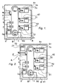
- a device A for handling banknotes comprising a transporting system 1, an infeeding and outfeeding unit 2 arranged along the transporting system 1, which unit is adapted to the infeed and outfeed of banknotes, an identifying unit 3 arranged along the transporting system 1, as well as a first, second and so on to a last storage unit 41, 42, ..., 4n, being arranged along the transporting system, each one adapted to the storage of banknotes, should accordingly be described.
- each unit may be composed of an infeeding unit and an outfeeding unit.
- the present invention is not depending on this and it should be appreciated that the following description of the mechanical part of the device only is for the purpose of exemplifying in order to facilitate the understanding of the present invention.
- the respective storage unit 41, 42, ..., 4n is adapted to store banknotes of a certain denomination and currency and the number of storage units is depending on how many currencies and denominations, respectively, that the device A should be able to handle.
- One of the objects of the invention is that the device readily should be able to be adapted to those currencies and denominations that a user want to be able to handle, among other things by the fact that the device readily can be rescaled by adding or removing storage units.
- the device A is adapted to an infeed of a banknote through the infeeding and outfeeding unit 2, a transportation of the banknote by means of the transporting system 1 past the identifying unit 3.
- An identification of the banknote takes place by means of the identifying unit 3, and then the banknote is transported to a storage unit intended for the banknote according to the identification where the banknote is fed into the intended storage unit from the transporting system.
- the device A comprises a central control unit 5, adapted to, by means of a communication system B, communicate with a first local control unit 51 arranged at the first storage unit 41, a second local control unit 52 arranged at the second storage unit 42 and so on to a last local control unit 5n arranged at the last storage unit 4n.
- central control unit 5 is adapted to communicate with a position sensor 6, as well as the identifying unit 3.
- the central control unit 5 and the respective local control unit 41, 42, ..., 4n have a common synchronous apprehension of the position of the transporting system.
- the central control unit 5 communicates the position of the banknote to the local control unit intended for the identified banknote, here exemplified by the second storage unit 42 having the second local control unit 52 associated therewith.
- the identifying unit 3 is located before the position sensor 6 in the direction of the transporting system 1.
- the mutual order between these components is not crucial to the function of the invention.
- the intended local control unit 52 directs the storage unit 42 associated therewith to an infeed, being independent of other units, of the banknote from the transporting system 1 to the storage unit 42 when the banknote reaches the intended storage unit 42.
- the present invention teaches that the communication between the central control unit 5 and intended local control unit 42 takes place before the banknote reaches the first storage unit 41 in order to guarantee that intended storage unit, even the first storage unit 41, should have time to get information about that the arriving banknote should be stored before the banknote reaches the storage unit.
- An outfeed of a banknote from the device takes place by the fact that the central control unit 5 is adapted to communicate to the local control unit associated with the storage unit that stores the banknote, here exemplified by the first storage unit 41 and the first local control unit 51 associated therewith, that a banknote should be fed out to the transporting system 1.
- the local control unit 51 directs the storage unit 41 associated therewith to an outfeed of the banknote to the transporting system, and then it is transported by means of the transporting system 1 to the infeeding and outfeeding unit 2, which feeds out the banknote from the transporting system 1 and out of the device A.
- a banknote may be damaged somehow, or two banknotes may be fed in so they overlap each other. It may also be the case that two or more banknotes are fed in entirely overlapping each other so that they visually seen look like one banknote.
- the identifying unit 3 can be adapted to, from the thickness of what is regarded to be one banknote, sense that it in effect is two or more banknotes.
- the identifying unit 3 is incapable of identifying a fed-in banknote with a particular certainty.
- the present invention teaches that the banknote should be transported by means of the transporting system 1 to the infeeding and outfeeding unit 2, which feeds out the unidentified banknote from the transporting system 1 and out of the device A.
- the infeeding and outfeeding unit 2 is adapted to feed in each banknote to the transporting system 1 that is inserted in device A, and to feed out each banknote from the transporting system 1 that, by means of the transporting system 1, reaches the infeeding and outfeeding unit 2.
- the transporting system 1 could be able to reverse back a banknote past the identifying unit 3 for at least one additional transportation of the banknote past the identifying unit 3 for identification before the identifying unit 3 is regarded to be incapable of identifying the banknote.
- an infeeding and outfeeding control unit 21' is adapted to communicate with the central control unit 5, arranged at the infeeding and outfeeding unit 2'.
- the infeeding and outfeeding control unit 21' has an apprehension of the position of the transporting system 1 that is common to and synchronous with other control units 5, 51, 52, ..., 5n.
- the central control unit 5 Upon an outfeed of a banknote from the device A, the central control unit 5 is adapted to communicate to the local control unit 51 associated with the storage unit 41 that stores the banknote and to the infeeding and outfeeding control unit 21' a position of the banknote in the transporting system.
- the local control unit 51 directs storage unit 41 associated therewith to an outfeed of the banknote to the transporting system 1 at the given position.
- the banknote is then transported to the infeeding and outfeeding unit 2', and the infeeding and outfeeding control unit 21' directs the infeeding and outfeeding unit 2' to an outfeed of banknote from the transporting system 1 and out of the device A in the position.
- a banknote can be permitted to be transported around a plurality of turns, and accordingly a plurality of times past the identifying unit 3, for identification before the identifying unit 3 is regarded to be incapable of identifying the banknote.
- Said embodiment also offers a possibility of adapting the central control unit 5, upon an infeed of a banknote to the transporting system 1 by means of the infeeding and outfeeding unit 2', to communicate a position of the infeed to the transporting system 1 to the infeeding and outfeeding control unit 21', and then the infeeding and outfeeding control unit 21' directs the infeeding and outfeeding unit 2' to an infeed of the banknote into the device A and to the transporting system 1 in this position.
- the central control unit 5 comprises a central index 5a, which comprises a record of each position associated with the transporting system 1, which index contains information about whether the respective position in the transporting system 1 carries a banknote or not.
- a central index 5a which comprises a record of each position associated with the transporting system 1, which index contains information about whether the respective position in the transporting system 1 carries a banknote or not.
- the present invention teaches that the transporting system is allocated positional locations of a mutual distance that in any position permits a transportation of at least a banknote being largest in physical size of the banknotes that may be present in the handling of banknotes.
- the present invention teaches that said infeeding and outfeeding unit 2 and the respective storing unit 41, 42, ..., 4n are adapted to an infeed and outfeed of banknotes taking place synchronously with the motion of the transporting system 1.
- the central control unit 5 is adapted to be able to read the apprehension of the respective local control unit 51, 52, ..., 5n and of the possible infeeding and outfeeding control unit 21' regarding the position of the transporting system 1.
- This reading may constitute a part of a performance inspection carried out upon a stationary transporting system 1.
- an initiation of the device A can be effected by the fact that the central control unit 5 is adapted to communicate a reference position of the transporting system 1 to all other control units 51, 52, ..., 5n (21') upon a stationary transporting system.
- An update of the device A can be effected by the fact that a current position of the transporting system 1 is communicated to all control units 5, 51, 52, ..., 5n (21') upon a new position of the transporting system, where said current position can be communicated upon a transporting system 1 in motion, and where the communication takes place autonomously.
- the central control unit 5 is adapted to communicate the identical numerical value x of the position of said transporting system to all local control units upon the initiation and update.
- Figure 4 shows that the central control unit 5 is adapted to calculate and communicate relative position readings r adapted to the respective local storage unit 41, 42, ..., 4n upon the indication of the position of a banknote in the transporting system 1.
- a relative value is calculated and communicated to this unit for an outfeed of a banknote from the correct position of the transporting system.
- the present invention teaches that the central control unit 5 communicates with other control units 51, 52, ..., 5n (21') by means of a common data link B1 having low bandwidth requirements, which may constitute a part of the communication system B.
- the present invention further teaches that the respective control unit 5, 51, 52, ..., 5n (21') comprises an index 7, 71, 72, ..., 7n, (70) that is adapted to be incremented in order to always represent the current position of the transporting system 1, that the respective index is adapted to handle positions that exceed a number of turns around the transporting system 1, that, when the respective index is incremented from the maximum value thereof, the respective index gets the value of 0 (zero), and that all calculations are made modulo the maximum value of the respective index + 1, whereby position distances above wrap around do not constitute any problem.
- the present invention teaches that the instantaneous position of the transporting system 1 in operation is communicated to the respective control unit 5, 51, 52, ..., 5n (21') by means of a transfer mechanism B2 adapted to utilize two signals in quadrature, and that a third signal is used for the zero setting of the respective index upon an initiation of the device.
- the figures show that the transfer mechanism B2 constitutes a part of the physical communication system B, but it should be appreciated that the transfer mechanism B2 is logically separated from the data link B1. It should also be appreciated that the data link B1 and the transfer mechanism B2 can be realised by two communication systems separated from each other.
Landscapes
- Physics & Mathematics (AREA)
- General Physics & Mathematics (AREA)
- Controlling Sheets Or Webs (AREA)
- Control Of Vending Devices And Auxiliary Devices For Vending Devices (AREA)
- Inspection Of Paper Currency And Valuable Securities (AREA)
- Delivering By Means Of Belts And Rollers (AREA)
Claims (20)
- Vorrichtung (A) zur Handhabung von Banknoten, die ein Transport-System (1), eine Ein- und Ausführeinheit (2), die entlang des Transport-Systems (1) angeordnet ist, wobei die Einheit für das Einführen und das Ausführen von Banknoten geeignet ist, eine Identifikationseinheit (3), die entlang des Transport-Systems (1) angeordnet ist, sowie eine erste, zweite usw, bis zu einer letzten Lagereinheit (41,42, ..., 4n), die entlang des Transport-Systems angeordnet sind, wobei jede zur Lagerung von Banknoten geeignet ist, umfasst, wobei die Vorrichtung (A) ausgelegt ist, eine Banknote durch die Ein- und Ausführeinheit einzuführen, die Banknote durch das Transport-System (1) an der ldentifikationseinheit (3) vorbei zu transportieren, die Banknote durch die Identifikationseinheit (3) zu identifizieren, die Banknote zu einer Lagereinheit (41, 42, ..., 4n), die für die Banknote entsprechend der Identifikation bestimmt ist, zu transportieren, sowie die Banknote zu der bestimmten Lagereinheit (41, 42, ..., 4n) von dem Transport-System (1) einzuführen, dadurch gekennzeichnet, dass die Vorrichtung (A) eine zentrale Steuereinheit (5) aufweist, die dafür geeignet ist, mit einer ersten lokalen Steuereinheit (51), die an der ersten Lagereinheit (41) angeordnet ist, einer zweiten lokalen Steuereinheit (52), die an der zweiten Lagereinheit (42), usw. bis zu einer letzten lokalen Steuereinheit (5n), die an der letzten Lagereinheit (4n) angeordnet ist, einem Positionssensor (6) sowie der Identifikationseinheit (3) in Verbindung zu stehen, dass die zentrale und die jeweilige lokale Steuereinheit (5, 51, 52, ..., 5n) eine gemeinsame synchrone Erfassung der Position des Transport-Systems (1) haben, so dass, sobald die Identifikationseinheit (3) eine Banknote identifiziert hat, und sobald die Position der Banknote in dem Transport-System (1) von dem Positionssensor (6) festgestellt ist, die zentrale Steuereinheit (5) die Position der Banknote an die lokale Steuereinheit übermittelt, die für die identifizierte Banknote bestimmt ist, und dass die bestimmte lokale Steuereinheit die ihr zugeordnete Lagereinheit zu einem Einführen der Banknote durch das Transport-System bis zu der Lagereinheit anweist, sobald die Banknote die bestimmte Lagereinheit erreicht, wobei das Einführen unabhängig von anderen Einheiten ist.
- Vorrichtung nach Anspruch 1, dadurch gekennzeichnet, dass die Kommunikation zwischen der zentralen Steuereinheit (5) und der bestimmten lokalen Steuereinheit stattfindet, bevor die Banknote die erste Lagereinheit (41) erreicht.
- Vorrichtung nach Anspruch 1 oder 2, dadurch gekennzeichnet, dass bei einem Auswurf einer Banknote aus der Vorrichtung (A), die zentrale Steuereinheit (5) geeignet ist, der lokalen Steuereinheit, die der Lagereinheit, die die Banknoten lagert, zugeordnet ist, zu übermitteln, dass die Banknote an das Transport-System ausgeführt werden soll, dass die lokale Steuereinheit die ihr zugeordnete Lagereinheit anweist, die Banknote an das Transport-System (1) auszuführen, dass die Banknote durch das Transport-System (1) zu der Ein- und Ausführeinheit transportiert wird, und dass die Ein- und Ausführeinheit (2) die Banknote aus dem Transport-System (1) und aus der Vorrichtung (A) ausführt.
- Vorrichtung nach Anspruch 3, dadurch gekennzeichnet, dass, falls die Identifizierungseinheit (3) nicht in der Lage ist, eine eingeführte Banknote mit einer bestimmten Sicherheit zu identifizieren, die Banknote durch das Transport-System (1) zu der Ein- und Ausführeinheit (2) transportiert wird, und dass die Ein- und Ausführeinheit (2) die unidentifizierte Banknote aus dem Transport-System (1) und aus der Vorrichtung (A) ausführt.
- Vorrichtung nach Anspruch 3 oder 4, dadurch gekennzeichnet, dass die Ein- und Ausführeinheit (2) geeignet ist, jede Banknote, die in die Vorrichtung (A) eingeführt wird, in das Transport-System (1) einzuführen, und jede Banknote aus dem Transport-System (1) auszuführen, die durch das Transport-System die Ein- und Ausführeinheit (2) erreicht.
- Vorrichtung nach Anspruch 4 und 5, dadurch gekennzeichnet, dass das Transport-System (1) die Banknote zurück hinter die Identifizierungseinheit (3) führt, um mindestens einen zusätzlichen Transport vorbei an der ldentifizierungseinheit (3) zu bewirken, bevor die ldentifizierungseinheit als nicht in der Lage zu sein betrachtet wird, die Banknote zu identifizieren.
- Vorrichtung nach Anspruch 3, dadurch gekennzeichnet, dass eine Ein- und Ausführ-Steuereinheit (21'), die geeignet ist, mit der zentralen Steuereinheit (5) in Verbindung zu stehen, an der Ein- und Ausführeinheit (2') angeordnet ist, dass die Ein- und Ausführ-Steuereinheit (21') eine Erfassung der Position des Transport-Systems (1) aufweist, die gleich und synchron mit anderen Steuereinheiten ist, dass bei einem Auswurf einer Banknote aus der Vorrichtung (A) die zentrale Steuereinheit (5) geeignet ist, der lokalen Steuereinheit, die der Lagereinheit, die die Banknote lagert, zugeordnet ist, und der Ein- und Ausführ-Steuereinheit (21') eine Position der Banknote in dem Transport-System (1) zu übermitteln, dass die lokale Steuereinheit die ihr zugeordnete Lagereinheit zu einem Ausführen der Banknote zu dem Transport-System (1) in der Position anweist, dass die Banknote durch das Transport-System (1) zu der Ein- und Ausführeinheit (2') transportiert wird, und dass die Ein- und Ausführ-Steuereinheit (21') die Ein- und Ausführeinheit (2') zu einem Ausführen der Banknote aus dem Transport-System (1) und aus der Vorrichtung (A) in der Position anweist.
- Vorrichtung nach Anspruch 4 und 7, dadurch gekennzeichnet, dass eine Banknote zur Identifizierung mehrere Runden transportiert werden kann und folglich mehrere Male an der ldentifizierungseinheit (3) vorbei transportiert werden kann, bevor die Identifizierungsehheit als nicht in der Lage zu sein betrachtet wird, die Banknote zu identifizieren.
- Vorrichtung nach einem der Ansprüche 7 oder 8, dadurch gekennzeichnet, dass die zentrale Steuereinheit (5), nach einer Einführung einer Banknote in das Transport-System (1) durch die Ein- und Ausführeinheit (2'), geeignet ist, eine Position der Einführung in das Transport-System an die Ein- und Ausführ-Steuereinheit (21) zu übermitteln, und dass die Ein- und Ausführ-Steuereinheit (21') die Ein- und Ausführeinheit (2') zu einem Einführen der Banknote in die Vorrichtung (A) und zu dem Transport-System (1) in der Position anweist.
- Vorrichtung nach einem der vorhergehenden Ansprüche, dadurch gekennzeichnet, dass die zentrale Steuereinheit (5) einen Hauptindex (5a) umfasst, der eine Aufzeichnung jeder Position, die mit dem Transport-System (1) verknüpft ist, aufweist, und dass der Index (5a) Informationen darüber umfasst, ob die entsprechende Position in dem Transport-System (1) eine Banknote trägt oder nicht.
- Vorrichtung nach einem der vorhergehenden Ansprüche, dadurch gekennzeichnet, dass dem Transport-System (1) Lagepositionen in einer beiderseitigen Entfernung zugewiesen werden, die in jeder Position einen Transport von mindestens einer Banknote erlaubt, deren physische Größe die größte von jenen Banknoten ist, die in der Banknoten-Handhabung vorhanden sind.
- Vorrichtung nach einem der vorhergehenden Ansprüche, dadurch gekennzeichnet, dass die Ein- und Ausführeinheit (2) und die entsprechende Lagereinheit (41, 42, ..., 4n) geeignet sind, Banknoten einzuführen und auszuführen, was synchron mit der Bewegung des Transport-Systems (1) erfolgt.
- Vorrichtung nach einem der vorhergehenden Ansprüche, dadurch gekennzeichnet, dass die zentrale Steuereinheit (5) geeignet ist, bezüglich der Position des Transport-Systems (1) die Erfassung aus der entsprechenden lokalen Steuereinheit (51, 52, ..., 5n) und der Ein- und Ausführ-Steuereinheit (21') beim Vorliegen einer solchen, zu lesen.
- Vorrichtung nach Anspruch 13, dadurch gekennzeichnet, dass das Lesen Teil einer Leistungsüberprüfung bildet, die an einem stationären Transport-System ausgeführt wird.
- Vorrichtung nach einem der vorhergehenden Ansprüche, dadurch gekennzeichnet, dass ein Start der Vorrichtung (A) durch den Umstand erfolgen kann, dass die zentrale Steuereinheit (5) geeignet ist, eine Referenzposition des Transport-Systems (1) an alle anderen Steuereinheiten bei einem stationären Transport-System zu übermitteln.
- Vorrichtung nach einem der vorhergehenden Ansprüche, dadurch gekennzeichnet, dass eine Aktualisierung der Vorrichtung (A) durch den Umstand erfolgen kann, dass eine aktuelle Position des Transport-Systems (1) an alle Steuereinheiten bei einer neuen Position des Transport-Systems übermittelt wird, dass die aktuelle Position nach einem in Bewegung befindlichen Transport-System (1) übermittelt werden kann und dass diese Übermittlung autonom erfolgt.
- Vorrichtung nach Anspruch 15 und 16, dadurch gekennzeichnet, dass die zentrale Steuereinheit (5) geeignet ist, den identischen numerischen Wert der Position des Transport-Systems (1) an alle lokalen Steuereinheiten nach dem Start und der Aktualisierung zu übermitteln, und dass die zentrale Steuereinheit geeignet ist, relative Positionsmessungen, die an die entsprechende Lagereinheit nach der Angabe der Position einer Banknote in dem Transport-System angepasst sind, zu berechnen und zu übermitteln.
- Vorrichtung nach einem der vorhergehenden Ansprüche, dadurch gekennzeichnet, dass die zentrale Steuereinheit (5) mit anderen Steuereinheiten durch eine gemeinsame Datenverbindung, die geringe Bandbreitenanforderungen hat, in Verbindung steht.
- Vorrichtung nach einem der vorhergehenden Ansprüche, dadurch gekennzeichnet, dass die entsprechende Steuereinheit (5, 51, 52, ..., 5n, 21') einen Index (7, 71, 72, ..., 7n, 70) aufweist, der inkrementiert wird, um ständig die aktuelle Position des Transport-Systems (1) darzustellen, dass der entsprechende Index geeignet ist, Positionen zu handhaben, die eine Anzahl von Umdrehungen um das Transport-System (1) übersteigen, so dass, falls der entsprechende Index über diesen Maximalwert erhöht wird, der entsprechende Index auf den Wert 0 (null) gesetzt wird, und dass alle Berechnungen Modulo den Maximalwert des entsprechenden Index + 1 durchgeführt werden.
- Vorrichtung nach Anspruch 15 und 19, dadurch gekennzeichnet, dass ein Übertragungsmechanismus (B2) geeignet ist, die momentane Position des Transport-Systems (1) während des Betriebs an die entsprechende Steuereinheit (5, 51, 52, ..., 5n, 21') durch die Verwendung zweier phasenverschobener Signale zu übermitteln, und dass die Vorrichtung geeignet ist, durch ein drittes Signal, das für die Nullsetzung des entsprechenden Index benutzt wird, gestartet zu werden.
Applications Claiming Priority (2)
| Application Number | Priority Date | Filing Date | Title |
|---|---|---|---|
| SE0400011A SE527837C2 (sv) | 2004-01-08 | 2004-01-08 | Styrsystem för sedelhanterare |
| PCT/SE2005/000009 WO2005066903A1 (en) | 2004-01-08 | 2005-01-07 | A control system for a banknote handler |
Publications (2)
| Publication Number | Publication Date |
|---|---|
| EP1709596A1 EP1709596A1 (de) | 2006-10-11 |
| EP1709596B1 true EP1709596B1 (de) | 2008-07-02 |
Family
ID=31492996
Family Applications (1)
| Application Number | Title | Priority Date | Filing Date |
|---|---|---|---|
| EP05704683A Expired - Lifetime EP1709596B1 (de) | 2004-01-08 | 2005-01-07 | Steuersystem für eine banknoten-handhabungsvorrichtung |
Country Status (6)
| Country | Link |
|---|---|
| US (1) | US7694877B2 (de) |
| EP (1) | EP1709596B1 (de) |
| AT (1) | ATE400042T1 (de) |
| DE (1) | DE602005007853D1 (de) |
| SE (1) | SE527837C2 (de) |
| WO (1) | WO2005066903A1 (de) |
Families Citing this family (8)
| Publication number | Priority date | Publication date | Assignee | Title |
|---|---|---|---|---|
| SE527837C2 (sv) * | 2004-01-08 | 2006-06-20 | Unjo Ab | Styrsystem för sedelhanterare |
| DE102006058549A1 (de) * | 2006-12-12 | 2008-06-19 | Wincor Nixdorf International Gmbh | Vorrichtung und Verfahren zur Handhabung von Banknoten |
| JP2010195514A (ja) * | 2009-02-24 | 2010-09-09 | Toshiba Corp | 紙葉類処理装置 |
| US9159180B2 (en) * | 2011-12-20 | 2015-10-13 | Ncr Corporation | Media conveying |
| JP5900251B2 (ja) * | 2012-09-03 | 2016-04-06 | 沖電気工業株式会社 | 紙幣処理装置 |
| CN102930633B (zh) | 2012-10-25 | 2014-08-20 | 广州广电运通金融电子股份有限公司 | 金融自助设备及其钞票识别模块和识别方法 |
| DE102012024397A1 (de) * | 2012-12-13 | 2014-06-18 | Giesecke & Devrient Gmbh | System und Verfahren zur Auswertung eines Stroms von Sensordaten für Wertdokumente |
| CN107527425B (zh) * | 2017-08-23 | 2019-09-20 | 深圳怡化电脑股份有限公司 | 一种传感器状态上报方法、系统、设备和存储介质 |
Family Cites Families (39)
| Publication number | Priority date | Publication date | Assignee | Title |
|---|---|---|---|---|
| US3608690A (en) * | 1969-05-26 | 1971-09-28 | Technology Systems Inc | Apparatus and methods for registering cash, registering a sale, and automatically dispensing change |
| US4179685A (en) * | 1976-11-08 | 1979-12-18 | Abbott Coin Counter Company, Inc. | Automatic currency identification system |
| JPS5633757A (en) * | 1979-08-24 | 1981-04-04 | Omron Tateisi Electronics Co | Circulating money reception/payment device |
| US4511794A (en) * | 1981-11-18 | 1985-04-16 | Omron Tateisi Electronics Co. | System for performing transactions |
| US4744468A (en) * | 1983-11-04 | 1988-05-17 | Laurel Bank Machine Co., Ltd. | Circulation-type bill receiving and dispensing machine |
| US4552350A (en) * | 1984-03-28 | 1985-11-12 | Ncr Corporation | Transport for diverted and purged sheets in a sheet dispenser |
| SE446567B (sv) * | 1985-08-01 | 1986-09-22 | Inter Innovation Ab | Anordning for inmatning av verdepapper, sasom sedlar, checkar etc, fran en utifran atkomlig inmatningsoppning till ett for forvaring av verdepapper avsett utrymme |
| US4775783A (en) * | 1985-08-02 | 1988-10-04 | Hitachi, Ltd. | Transaction system |
| US4745266A (en) * | 1985-09-25 | 1988-05-17 | Laurel Bank Machines Co., Ltd. | Bill bundle drawing out apparatus |
| JP2624674B2 (ja) * | 1987-04-10 | 1997-06-25 | 株式会社日立製作所 | 取引処理システム |
| ATE114065T1 (de) * | 1989-01-26 | 1994-11-15 | Mars Inc | Vorrichtung zur annahme und abgabe von banknoten und verfahren zu deren betrieb. |
| JPH02306390A (ja) * | 1989-05-22 | 1990-12-19 | Toshiba Corp | 自動取引装置 |
| US6012565A (en) * | 1997-05-07 | 2000-01-11 | Cummins-Allison Corp. | Intelligent currency handling system |
| JPH05262312A (ja) * | 1991-06-04 | 1993-10-12 | Ncr Corp | 用紙取り扱い装置 |
| GB9319180D0 (en) * | 1993-09-16 | 1993-11-03 | Ncr Int Inc | Automated financial system |
| GB9426341D0 (en) * | 1994-12-29 | 1995-03-01 | At & T Global Inf Solution | A transaction terminal |
| DE19536481A1 (de) * | 1995-09-29 | 1997-04-03 | Siemens Nixdorf Inf Syst | Geldannahme- und -ausgabeautomat |
| IT1285312B1 (it) * | 1996-03-13 | 1998-06-03 | Cts Electronics Srl | Dispositivo di acquisizione e/o rilascio per banconote |
| US6749111B2 (en) * | 1997-11-28 | 2004-06-15 | Diebold, Incorporated | Automated banking machine |
| US6131809A (en) * | 1997-11-28 | 2000-10-17 | Diebold, Incorporated | Control system communication apparatus and method for currency recycling automated banking machine |
| EP2378491A3 (de) * | 1998-06-26 | 2016-01-20 | Hitachi-Omron Terminal Solutions, Corp. | Banknoteneinzahlungs-/-auszahlungsmaschine |
| JP4135238B2 (ja) * | 1998-12-08 | 2008-08-20 | 日立オムロンターミナルソリューションズ株式会社 | 紙幣入出金機 |
| GB9906582D0 (en) * | 1999-03-22 | 1999-05-19 | Rue De Int Ltd | Sheet handling system |
| JP3815651B2 (ja) * | 1999-10-19 | 2006-08-30 | 日立オムロンターミナルソリューションズ株式会社 | 紙幣入出金機 |
| JP3959706B2 (ja) * | 2001-03-01 | 2007-08-15 | 日立オムロンターミナルソリューションズ株式会社 | 紙幣取扱装置 |
| JP4939695B2 (ja) * | 2001-04-19 | 2012-05-30 | 株式会社東芝 | 紙幣処理装置 |
| JP2002316745A (ja) * | 2001-04-20 | 2002-10-31 | Toshiba Corp | 紙葉類処理装置 |
| DE10123383A1 (de) * | 2001-05-14 | 2003-01-16 | Giesecke & Devrient Gmbh | Verfahren und Vorrichtung zum Öffnen und Schließen einer Kassette |
| US6626298B2 (en) * | 2001-05-18 | 2003-09-30 | Cashcan Corp. | High speed bill sorter with parallel data processors |
| US7387236B2 (en) * | 2001-10-09 | 2008-06-17 | Delaware Capital Formation, Inc. | Dispensing of currency |
| SE521081C2 (sv) | 2001-12-13 | 2003-09-30 | Texdot Ab | Skrivarhuvudstruktur och metod för att öka den maximala styrfrekvensen i en vätskestrålskrivare |
| US20030113910A1 (en) | 2001-12-18 | 2003-06-19 | Mike Levanduski | Pluripotent stem cells derived without the use of embryos or fetal tissue |
| US7066335B2 (en) * | 2001-12-19 | 2006-06-27 | Pretech As | Apparatus for receiving and distributing cash |
| JP3754922B2 (ja) * | 2001-12-26 | 2006-03-15 | 日立オムロンターミナルソリューションズ株式会社 | 紙幣取扱装置 |
| KR100675238B1 (ko) * | 2002-08-30 | 2007-01-30 | 후지쯔 가부시끼가이샤 | 입금기 |
| WO2004061787A2 (en) * | 2002-12-31 | 2004-07-22 | Diebold, Incorporated | Atm currency cassette arrangement |
| SE527837C2 (sv) * | 2004-01-08 | 2006-06-20 | Unjo Ab | Styrsystem för sedelhanterare |
| JP4704777B2 (ja) * | 2004-06-01 | 2011-06-22 | 日立オムロンターミナルソリューションズ株式会社 | 紙幣入出金機 |
| US20070205260A1 (en) * | 2005-12-16 | 2007-09-06 | Ncr Corporation | Media pick unit |
-
2004
- 2004-01-08 SE SE0400011A patent/SE527837C2/sv not_active IP Right Cessation
-
2005
- 2005-01-07 EP EP05704683A patent/EP1709596B1/de not_active Expired - Lifetime
- 2005-01-07 WO PCT/SE2005/000009 patent/WO2005066903A1/en not_active Ceased
- 2005-01-07 US US10/585,690 patent/US7694877B2/en not_active Expired - Fee Related
- 2005-01-07 DE DE602005007853T patent/DE602005007853D1/de not_active Expired - Lifetime
- 2005-01-07 AT AT05704683T patent/ATE400042T1/de not_active IP Right Cessation
Also Published As
| Publication number | Publication date |
|---|---|
| WO2005066903A1 (en) | 2005-07-21 |
| EP1709596A1 (de) | 2006-10-11 |
| US7694877B2 (en) | 2010-04-13 |
| US20080283450A1 (en) | 2008-11-20 |
| DE602005007853D1 (de) | 2008-08-14 |
| SE0400011D0 (sv) | 2004-01-08 |
| SE0400011L (sv) | 2005-07-09 |
| ATE400042T1 (de) | 2008-07-15 |
| SE527837C2 (sv) | 2006-06-20 |
Similar Documents
| Publication | Publication Date | Title |
|---|---|---|
| RU2414000C2 (ru) | Устройство и способ для хранения и выдачи банкнот | |
| US8505707B2 (en) | Money handling machine | |
| SE505484C2 (sv) | Anordning för in- och utmatning av värdepapper | |
| EP1709596B1 (de) | Steuersystem für eine banknoten-handhabungsvorrichtung | |
| JP2012198764A (ja) | 貨幣処理装置 | |
| EP3584771B1 (de) | Bankautomat und banknotenverarbeitungsverfahren | |
| JPWO2012127525A1 (ja) | 紙幣処理装置 | |
| KR900013431A (ko) | 자동출납 장치에서 보충지폐를 전송하기 위한 방법 및 장치 | |
| EP1123540B1 (de) | System zur behandlung von banknoten in einem geographisch begrenztem gebiet | |
| WO2011039833A1 (ja) | 紙幣処理システム | |
| US10515502B2 (en) | Paper sheet handling machine and paper sheet handling method | |
| JP2009238150A (ja) | 釣銭機システム | |
| KR20170031365A (ko) | 금융자동화기기의 지폐류 저장장치 | |
| JP2010117916A (ja) | 紙葉類処理装置及びそれを備えた紙幣入出金装置 | |
| JP4365574B2 (ja) | 紙幣処理装置 | |
| RU2636017C1 (ru) | Способ пересчета и сортировки банкнот | |
| CN105608786A (zh) | 致动器和介质交易装置 | |
| US20210331886A1 (en) | Conveying direction switching apparatus and paper sheet handling apparatus | |
| WO2010038265A1 (ja) | 紙幣処理装置 | |
| JP2014182782A (ja) | 紙幣収納繰出し機構、及び紙幣処理装置、及びシステム | |
| JP5242277B2 (ja) | 紙幣処理装置 | |
| KR101611703B1 (ko) | 매체 분기 장치 및 금융기기 | |
| KR20160097846A (ko) | 금융자동화기기 및 금융자동화기기의 게이트 롤러 | |
| EP1243537A1 (de) | Speichereinrichtung für Banknoten | |
| JP2005259084A (ja) | 紙葉類取扱装置の構築方法、及び紙葉類カセット |
Legal Events
| Date | Code | Title | Description |
|---|---|---|---|
| PUAI | Public reference made under article 153(3) epc to a published international application that has entered the european phase |
Free format text: ORIGINAL CODE: 0009012 |
|
| 17P | Request for examination filed |
Effective date: 20060808 |
|
| AK | Designated contracting states |
Kind code of ref document: A1 Designated state(s): AT BE BG CH CY CZ DE DK EE ES FI FR GB GR HU IE IS IT LI LT LU MC NL PL PT RO SE SI SK TR |
|
| DAX | Request for extension of the european patent (deleted) | ||
| 17Q | First examination report despatched |
Effective date: 20070402 |
|
| GRAP | Despatch of communication of intention to grant a patent |
Free format text: ORIGINAL CODE: EPIDOSNIGR1 |
|
| GRAS | Grant fee paid |
Free format text: ORIGINAL CODE: EPIDOSNIGR3 |
|
| GRAA | (expected) grant |
Free format text: ORIGINAL CODE: 0009210 |
|
| AK | Designated contracting states |
Kind code of ref document: B1 Designated state(s): AT BE BG CH CY CZ DE DK EE ES FI FR GB GR HU IE IS IT LI LT LU MC NL PL PT RO SE SI SK TR |
|
| REG | Reference to a national code |
Ref country code: GB Ref legal event code: FG4D |
|
| REG | Reference to a national code |
Ref country code: CH Ref legal event code: EP |
|
| REF | Corresponds to: |
Ref document number: 602005007853 Country of ref document: DE Date of ref document: 20080814 Kind code of ref document: P |
|
| REG | Reference to a national code |
Ref country code: IE Ref legal event code: FG4D |
|
| PG25 | Lapsed in a contracting state [announced via postgrant information from national office to epo] |
Ref country code: SI Free format text: LAPSE BECAUSE OF FAILURE TO SUBMIT A TRANSLATION OF THE DESCRIPTION OR TO PAY THE FEE WITHIN THE PRESCRIBED TIME-LIMIT Effective date: 20080702 |
|
| PG25 | Lapsed in a contracting state [announced via postgrant information from national office to epo] |
Ref country code: NL Free format text: LAPSE BECAUSE OF FAILURE TO SUBMIT A TRANSLATION OF THE DESCRIPTION OR TO PAY THE FEE WITHIN THE PRESCRIBED TIME-LIMIT Effective date: 20080702 |
|
| NLV1 | Nl: lapsed or annulled due to failure to fulfill the requirements of art. 29p and 29m of the patents act | ||
| PG25 | Lapsed in a contracting state [announced via postgrant information from national office to epo] |
Ref country code: LT Free format text: LAPSE BECAUSE OF FAILURE TO SUBMIT A TRANSLATION OF THE DESCRIPTION OR TO PAY THE FEE WITHIN THE PRESCRIBED TIME-LIMIT Effective date: 20080702 Ref country code: IS Free format text: LAPSE BECAUSE OF FAILURE TO SUBMIT A TRANSLATION OF THE DESCRIPTION OR TO PAY THE FEE WITHIN THE PRESCRIBED TIME-LIMIT Effective date: 20081102 |
|
| PG25 | Lapsed in a contracting state [announced via postgrant information from national office to epo] |
Ref country code: ES Free format text: LAPSE BECAUSE OF FAILURE TO SUBMIT A TRANSLATION OF THE DESCRIPTION OR TO PAY THE FEE WITHIN THE PRESCRIBED TIME-LIMIT Effective date: 20081013 Ref country code: FI Free format text: LAPSE BECAUSE OF FAILURE TO SUBMIT A TRANSLATION OF THE DESCRIPTION OR TO PAY THE FEE WITHIN THE PRESCRIBED TIME-LIMIT Effective date: 20080702 Ref country code: BG Free format text: LAPSE BECAUSE OF FAILURE TO SUBMIT A TRANSLATION OF THE DESCRIPTION OR TO PAY THE FEE WITHIN THE PRESCRIBED TIME-LIMIT Effective date: 20081002 Ref country code: AT Free format text: LAPSE BECAUSE OF FAILURE TO SUBMIT A TRANSLATION OF THE DESCRIPTION OR TO PAY THE FEE WITHIN THE PRESCRIBED TIME-LIMIT Effective date: 20080702 |
|
| PG25 | Lapsed in a contracting state [announced via postgrant information from national office to epo] |
Ref country code: BE Free format text: LAPSE BECAUSE OF FAILURE TO SUBMIT A TRANSLATION OF THE DESCRIPTION OR TO PAY THE FEE WITHIN THE PRESCRIBED TIME-LIMIT Effective date: 20080702 |
|
| PG25 | Lapsed in a contracting state [announced via postgrant information from national office to epo] |
Ref country code: EE Free format text: LAPSE BECAUSE OF FAILURE TO SUBMIT A TRANSLATION OF THE DESCRIPTION OR TO PAY THE FEE WITHIN THE PRESCRIBED TIME-LIMIT Effective date: 20080702 Ref country code: DK Free format text: LAPSE BECAUSE OF FAILURE TO SUBMIT A TRANSLATION OF THE DESCRIPTION OR TO PAY THE FEE WITHIN THE PRESCRIBED TIME-LIMIT Effective date: 20080702 |
|
| PLBE | No opposition filed within time limit |
Free format text: ORIGINAL CODE: 0009261 |
|
| STAA | Information on the status of an ep patent application or granted ep patent |
Free format text: STATUS: NO OPPOSITION FILED WITHIN TIME LIMIT |
|
| PG25 | Lapsed in a contracting state [announced via postgrant information from national office to epo] |
Ref country code: RO Free format text: LAPSE BECAUSE OF FAILURE TO SUBMIT A TRANSLATION OF THE DESCRIPTION OR TO PAY THE FEE WITHIN THE PRESCRIBED TIME-LIMIT Effective date: 20080702 Ref country code: CZ Free format text: LAPSE BECAUSE OF FAILURE TO SUBMIT A TRANSLATION OF THE DESCRIPTION OR TO PAY THE FEE WITHIN THE PRESCRIBED TIME-LIMIT Effective date: 20080702 Ref country code: SK Free format text: LAPSE BECAUSE OF FAILURE TO SUBMIT A TRANSLATION OF THE DESCRIPTION OR TO PAY THE FEE WITHIN THE PRESCRIBED TIME-LIMIT Effective date: 20080702 |
|
| 26N | No opposition filed |
Effective date: 20090403 |
|
| PG25 | Lapsed in a contracting state [announced via postgrant information from national office to epo] |
Ref country code: MC Free format text: LAPSE BECAUSE OF NON-PAYMENT OF DUE FEES Effective date: 20090131 Ref country code: IT Free format text: LAPSE BECAUSE OF FAILURE TO SUBMIT A TRANSLATION OF THE DESCRIPTION OR TO PAY THE FEE WITHIN THE PRESCRIBED TIME-LIMIT Effective date: 20080702 |
|
| REG | Reference to a national code |
Ref country code: CH Ref legal event code: PL |
|
| PG25 | Lapsed in a contracting state [announced via postgrant information from national office to epo] |
Ref country code: LI Free format text: LAPSE BECAUSE OF NON-PAYMENT OF DUE FEES Effective date: 20090131 Ref country code: CH Free format text: LAPSE BECAUSE OF NON-PAYMENT OF DUE FEES Effective date: 20090131 |
|
| PG25 | Lapsed in a contracting state [announced via postgrant information from national office to epo] |
Ref country code: SE Free format text: LAPSE BECAUSE OF FAILURE TO SUBMIT A TRANSLATION OF THE DESCRIPTION OR TO PAY THE FEE WITHIN THE PRESCRIBED TIME-LIMIT Effective date: 20081002 Ref country code: IE Free format text: LAPSE BECAUSE OF NON-PAYMENT OF DUE FEES Effective date: 20090107 |
|
| PG25 | Lapsed in a contracting state [announced via postgrant information from national office to epo] |
Ref country code: PL Free format text: LAPSE BECAUSE OF FAILURE TO SUBMIT A TRANSLATION OF THE DESCRIPTION OR TO PAY THE FEE WITHIN THE PRESCRIBED TIME-LIMIT Effective date: 20080702 |
|
| PG25 | Lapsed in a contracting state [announced via postgrant information from national office to epo] |
Ref country code: GR Free format text: LAPSE BECAUSE OF FAILURE TO SUBMIT A TRANSLATION OF THE DESCRIPTION OR TO PAY THE FEE WITHIN THE PRESCRIBED TIME-LIMIT Effective date: 20081003 |
|
| PG25 | Lapsed in a contracting state [announced via postgrant information from national office to epo] |
Ref country code: LU Free format text: LAPSE BECAUSE OF NON-PAYMENT OF DUE FEES Effective date: 20090107 |
|
| PG25 | Lapsed in a contracting state [announced via postgrant information from national office to epo] |
Ref country code: HU Free format text: LAPSE BECAUSE OF FAILURE TO SUBMIT A TRANSLATION OF THE DESCRIPTION OR TO PAY THE FEE WITHIN THE PRESCRIBED TIME-LIMIT Effective date: 20090103 |
|
| PG25 | Lapsed in a contracting state [announced via postgrant information from national office to epo] |
Ref country code: TR Free format text: LAPSE BECAUSE OF FAILURE TO SUBMIT A TRANSLATION OF THE DESCRIPTION OR TO PAY THE FEE WITHIN THE PRESCRIBED TIME-LIMIT Effective date: 20080702 |
|
| PG25 | Lapsed in a contracting state [announced via postgrant information from national office to epo] |
Ref country code: CY Free format text: LAPSE BECAUSE OF FAILURE TO SUBMIT A TRANSLATION OF THE DESCRIPTION OR TO PAY THE FEE WITHIN THE PRESCRIBED TIME-LIMIT Effective date: 20080702 |
|
| PG25 | Lapsed in a contracting state [announced via postgrant information from national office to epo] |
Ref country code: PT Free format text: LAPSE BECAUSE OF FAILURE TO SUBMIT A TRANSLATION OF THE DESCRIPTION OR TO PAY THE FEE WITHIN THE PRESCRIBED TIME-LIMIT Effective date: 20080702 |
|
| PGFP | Annual fee paid to national office [announced via postgrant information from national office to epo] |
Ref country code: DE Payment date: 20140121 Year of fee payment: 10 |
|
| PGFP | Annual fee paid to national office [announced via postgrant information from national office to epo] |
Ref country code: FR Payment date: 20140131 Year of fee payment: 10 |
|
| PGFP | Annual fee paid to national office [announced via postgrant information from national office to epo] |
Ref country code: GB Payment date: 20140122 Year of fee payment: 10 |
|
| REG | Reference to a national code |
Ref country code: DE Ref legal event code: R119 Ref document number: 602005007853 Country of ref document: DE |
|
| GBPC | Gb: european patent ceased through non-payment of renewal fee |
Effective date: 20150107 |
|
| PG25 | Lapsed in a contracting state [announced via postgrant information from national office to epo] |
Ref country code: DE Free format text: LAPSE BECAUSE OF NON-PAYMENT OF DUE FEES Effective date: 20150801 Ref country code: GB Free format text: LAPSE BECAUSE OF NON-PAYMENT OF DUE FEES Effective date: 20150107 |
|
| REG | Reference to a national code |
Ref country code: FR Ref legal event code: ST Effective date: 20150930 |
|
| PG25 | Lapsed in a contracting state [announced via postgrant information from national office to epo] |
Ref country code: FR Free format text: LAPSE BECAUSE OF NON-PAYMENT OF DUE FEES Effective date: 20150202 |