EP1705453A1 - Verbundpanzerplatte zum Schutz von Fahrzeugen oder Gebäuden vor panzerbrechenden Geschossen mit hoher kinetischer Energie - Google Patents
Verbundpanzerplatte zum Schutz von Fahrzeugen oder Gebäuden vor panzerbrechenden Geschossen mit hoher kinetischer Energie Download PDFInfo
- Publication number
- EP1705453A1 EP1705453A1 EP06005843A EP06005843A EP1705453A1 EP 1705453 A1 EP1705453 A1 EP 1705453A1 EP 06005843 A EP06005843 A EP 06005843A EP 06005843 A EP06005843 A EP 06005843A EP 1705453 A1 EP1705453 A1 EP 1705453A1
- Authority
- EP
- European Patent Office
- Prior art keywords
- composite armor
- armor plate
- plate according
- hardness elements
- hardness
- Prior art date
- Legal status (The legal status is an assumption and is not a legal conclusion. Google has not performed a legal analysis and makes no representation as to the accuracy of the status listed.)
- Granted
Links
- 239000002131 composite material Substances 0.000 title claims abstract description 51
- 238000010304 firing Methods 0.000 claims abstract description 13
- 150000001875 compounds Chemical class 0.000 claims description 9
- 238000004382 potting Methods 0.000 claims description 9
- 239000007787 solid Substances 0.000 claims description 8
- 229910052751 metal Inorganic materials 0.000 claims description 6
- 239000002184 metal Substances 0.000 claims description 6
- 229910018072 Al 2 O 3 Inorganic materials 0.000 claims description 2
- QEAHZNBILUSCGM-UHFFFAOYSA-N B([O-])([O-])[O-].B(O)(O)O.B([O-])(O)O.[Ti+4] Chemical compound B([O-])([O-])[O-].B(O)(O)O.B([O-])(O)O.[Ti+4] QEAHZNBILUSCGM-UHFFFAOYSA-N 0.000 claims description 2
- 229910052580 B4C Inorganic materials 0.000 claims description 2
- INAHAJYZKVIDIZ-UHFFFAOYSA-N boron carbide Chemical compound B12B3B4C32B41 INAHAJYZKVIDIZ-UHFFFAOYSA-N 0.000 claims description 2
- 229910010293 ceramic material Inorganic materials 0.000 claims description 2
- 239000002657 fibrous material Substances 0.000 claims description 2
- 239000007769 metal material Substances 0.000 claims description 2
- HBMJWWWQQXIZIP-UHFFFAOYSA-N silicon carbide Chemical compound [Si+]#[C-] HBMJWWWQQXIZIP-UHFFFAOYSA-N 0.000 claims description 2
- 229910010271 silicon carbide Inorganic materials 0.000 claims description 2
- PNEYBMLMFCGWSK-UHFFFAOYSA-N Alumina Chemical compound [O-2].[O-2].[O-2].[Al+3].[Al+3] PNEYBMLMFCGWSK-UHFFFAOYSA-N 0.000 claims 1
- 239000000919 ceramic Substances 0.000 description 3
- 238000010276 construction Methods 0.000 description 2
- 229920001971 elastomer Polymers 0.000 description 2
- 239000011159 matrix material Substances 0.000 description 2
- 230000001681 protective effect Effects 0.000 description 2
- 229920000049 Carbon (fiber) Polymers 0.000 description 1
- 229910000760 Hardened steel Inorganic materials 0.000 description 1
- 239000004952 Polyamide Substances 0.000 description 1
- 229910000831 Steel Inorganic materials 0.000 description 1
- 239000004760 aramid Substances 0.000 description 1
- 229920003235 aromatic polyamide Polymers 0.000 description 1
- 239000004917 carbon fiber Substances 0.000 description 1
- 230000001419 dependent effect Effects 0.000 description 1
- 238000011161 development Methods 0.000 description 1
- 230000018109 developmental process Effects 0.000 description 1
- 239000000806 elastomer Substances 0.000 description 1
- 239000003822 epoxy resin Substances 0.000 description 1
- 230000002349 favourable effect Effects 0.000 description 1
- 239000003365 glass fiber Substances 0.000 description 1
- LNEPOXFFQSENCJ-UHFFFAOYSA-N haloperidol Chemical compound C1CC(O)(C=2C=CC(Cl)=CC=2)CCN1CCCC(=O)C1=CC=C(F)C=C1 LNEPOXFFQSENCJ-UHFFFAOYSA-N 0.000 description 1
- 239000000463 material Substances 0.000 description 1
- VNWKTOKETHGBQD-UHFFFAOYSA-N methane Chemical compound C VNWKTOKETHGBQD-UHFFFAOYSA-N 0.000 description 1
- 229910052574 oxide ceramic Inorganic materials 0.000 description 1
- 239000011224 oxide ceramic Substances 0.000 description 1
- TWNQGVIAIRXVLR-UHFFFAOYSA-N oxo(oxoalumanyloxy)alumane Chemical compound O=[Al]O[Al]=O TWNQGVIAIRXVLR-UHFFFAOYSA-N 0.000 description 1
- 239000008188 pellet Substances 0.000 description 1
- 239000004033 plastic Substances 0.000 description 1
- 229920003023 plastic Polymers 0.000 description 1
- 229920002647 polyamide Polymers 0.000 description 1
- 229920000647 polyepoxide Polymers 0.000 description 1
- 229920000728 polyester Polymers 0.000 description 1
- 229920002635 polyurethane Polymers 0.000 description 1
- 239000004814 polyurethane Substances 0.000 description 1
- 230000035939 shock Effects 0.000 description 1
- 239000007779 soft material Substances 0.000 description 1
- 239000010959 steel Substances 0.000 description 1
Images



Classifications
-
- F—MECHANICAL ENGINEERING; LIGHTING; HEATING; WEAPONS; BLASTING
- F41—WEAPONS
- F41H—ARMOUR; ARMOURED TURRETS; ARMOURED OR ARMED VEHICLES; MEANS OF ATTACK OR DEFENCE, e.g. CAMOUFLAGE, IN GENERAL
- F41H5/00—Armour; Armour plates
- F41H5/02—Plate construction
- F41H5/04—Plate construction composed of more than one layer
- F41H5/0492—Layered armour containing hard elements, e.g. plates, spheres, rods, separated from each other, the elements being connected to a further flexible layer or being embedded in a plastics or an elastomer matrix
-
- F—MECHANICAL ENGINEERING; LIGHTING; HEATING; WEAPONS; BLASTING
- F41—WEAPONS
- F41H—ARMOUR; ARMOURED TURRETS; ARMOURED OR ARMED VEHICLES; MEANS OF ATTACK OR DEFENCE, e.g. CAMOUFLAGE, IN GENERAL
- F41H5/00—Armour; Armour plates
- F41H5/02—Plate construction
- F41H5/023—Armour plate, or auxiliary armour plate mounted at a distance of the main armour plate, having cavities at its outer impact surface, or holes, for deflecting the projectile
Definitions
- the invention relates to a composite armor plate for the protection of vehicles or buildings from armor-piercing projectiles with high kinetic energy with the features of the preamble of claim 1.
- Composite armor plates containing at least one layer of high-hardness elements are known per se.
- EP 0843149 B1 there is disclosed a composite armor plate containing an inner layer of high density ceramics pellets disposed within a solidified material and which may also be cylindrical in shape.
- EP 0929788 B1 ceramic bodies are described for a composite armor plate, which are cylindrically shaped and have at least one convexly curved end surface.
- the invention has for its object to design a composite armor plate with the features of the preamble of claim 1 so that an extremely lightweight protective structure is realized against modern ammunition, which is able to ensure even with very close hit locations still excellent ballistic security ,
- the invention is based on the finding that it is important to realize a favorable impact angle when hitting a projectile, as this leads to an advanced break of the projectile core, especially in the high-hardness cores of modern ammunition. This optimizes the protective effect with a minimum basis weight.
- the basic idea of the invention is to provide the surfaces of the high-hardness elements facing the firing direction with a conical or pyramid-shaped end face. To the front, the conical or pyramidal surfaces can be closed, for example, open or by a potting compound and a cover layer.
- the back of the composite panel can be made of a solid Layer which has shock-absorbing properties and for certain applications can also have the highest possible tensile strength.
- the composite armor plate may be self-supporting mounted in a frame construction or applied to a housing made of armored steel.
- the high-hardness elements may consist of ceramic materials, that is, for example, of an aluminum oxide ceramic, wherein it has proved to be particularly advantageous if the Al 2 O 3 content is 96-99.9%.
- the high-hardness elements may also consist of boron carbide, silicon carbide or titanium triborate or else of a metallic material such as hardened steel.
- the high-hardness elements can be designed and arranged such that they have a triangular, quadrangular, pentagonal, hexagonal or generally polygonal cross-section in a plane parallel to the plate center plane, but they can also have a round or oval cross-section.
- Particularly advantageous high-hardness elements have proven to have a cylindrical body.
- the high-hardness elements may have a planar surface, but they may also have on this side an outwardly or inwardly projecting conical or pyramidal surface or concave inwardly curved.
- the majority of the high-hardness elements has an overall height in the direction normal to the plate center plane, which is in the range of 13-80 mm.
- the cylindrical basic body has at least one conical end face, in which the ratio of the cone height to the maximum diameter is in the range of 0.1 to 0.7. Furthermore, it is advantageous if the majority of the high-hardness elements of the cylindrical base body is formed with a ratio between the cylinder height and maximum diameter of 0.4 to 2.5.
- the tips of the conical or pyramid-shaped end faces may be rounded, the ratio between the radius of curvature of the rounded tips and the diameter of the largest cross section in a plane parallel to the plate center plane being less than 0.25.
- the space between the cones or pyramids on the face of the high-hardness elements may be filled with a potting compound which is connected to one or more continuous outer terminations. But it may also be advantageous if the space between the high-hardness elements is formed only to the base of the cones or pyramids on the end faces of the firing direction with a potting compound, such that the cones or pyramids are exposed to the outside.
- elastomers or plastics e.g. Polyurethane, epoxy resins, polyesters, rubber etc. can be used.
- the high-hardness element for a composite armor plate shown in Fig. 1 has a cylindrical body 1 with the height h in the direction normal to the plate center plane PM of the composite armor plate shown in Fig. 3 and the diameter d.
- the upper end face 1.1 of the main body 1, which in FIG. 1 faces the firing direction in the assembled state of the composite armor plate, has a tapered outward configuration.
- the cone has the height 1.
- the total height h + 1 can be in the range of 13-80 mm, while in the conical face 1.1 the ratio between the cone height 1 and the maximum diameter d of the main body in the range of 0.1 to 0, 7 can lie.
- the ratio between cylinder height h and maximum diameter d can be 0.4 to 2.5.
- FIG. 2 shows, as a further exemplary embodiment, a high-hardness element for a composite armor plate with a basic body 2 which has a pentagonal cross-section and has the height h 1 and the maximum diameter d 1 .
- the upper surface 2.1 of the main body 2, which faces the direction of bombardment in FIG. 2, is designed in the shape of a pyramid with the height l 1 .
- the tip of the cone or the pyramid can be rounded.
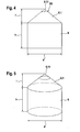
- the high-hardness element here has a main body 6, whose upper end face 6.1 facing the firing direction in the mounted state of the composite armor plate is conical, the tip of the cone having a rounding 6.11.
- the ratio between the radius of curvature R1 of the rounded tip and the diameter d of the largest cross-section of the base body 6 in a plane parallel to the plate-plane plane PM is advantageously less than 0.25.
- 6 and 7 show an embodiment of a high-hardness element with a cylindrical base body 7, whose upper end face 7.1 is cone-shaped, wherein the tip 7.11 of the cone is cut parallel to the plate center plane PM.
- FIGS. 8 and 9 show an embodiment of a high-hardness element with a cylindrical base body 8, the upper end face 8.1 is cone-shaped and in which the mounted in the assembled state of the composite armor plate facing away from the shooting direction back 8.2 is concave inwardly curved with the radius of curvature R2 ,
- Fig. 3 shows a highly schematic representation of a composite armor plate, which is equipped with high-hardness elements of FIG.
- the composite armor plate whose plate center plane is denoted by PM, has on the side facing the firing direction, which is referred to in Fig. 3 with "outside", a cover plate 4 and on the side facing away from the firing direction, in Fig. 3 with "inside is designated, ie the back, a base plate 3, which may be constructed in a manner not shown also of several layers having shock absorbing properties.
- one or more solid layers may be present, which consist of fiber material having a particularly high tensile strength, that is, for example, aramid, glass fiber, polyamide, carbon fiber, etc.
- the base plate 3 may be formed in a non-self-illustrated manner as a solid, existing metal layer, wherein the layer may also be part of a vehicle structure. If the base plate 3 is made up of several layers, the outermost layer on the rear side can be a solid layer of metal, in front of which further layers can be arranged. In this case, an air gap or an intermediate layer of soft material can be arranged between the outermost layer of metal and the inner layers. Above the base plate 3, the high-hardness elements I are arranged side by side with flat backs 1.2, wherein the main body of adjacent elements 1 may be in contact with each other.
- the space 5 between the cones 1.1 may be filled with a potting compound, which may be connected to the cover plate 4.
- the main body 1 of the high-ranking elements can likewise be arranged within a matrix of a potting compound. It is also possible to leave the spaces 5 between the cones free and fill the space between the bodies only to the base of the cone 1.1 with a potting compound, so that the conical tips are exposed to the outside.
Landscapes
- Engineering & Computer Science (AREA)
- General Engineering & Computer Science (AREA)
- Aiming, Guidance, Guns With A Light Source, Armor, Camouflage, And Targets (AREA)
- Vehicle Interior And Exterior Ornaments, Soundproofing, And Insulation (AREA)
- Building Environments (AREA)
- Buildings Adapted To Withstand Abnormal External Influences (AREA)
Abstract
Description
- Die Erfindung betrifft eine Verbundpanzerplatte zum Schutz von Fahrzeugen oder Gebäuden vor panzerbrechenden Geschossen mit hoher kinetischer Energie mit den Merkmalen aus dem Oberbegriff des Patentanspruchs 1.
- Verbundpanzerplatten, welche mindestens eine Lage aus hochharten Elementen enthalten, sind an sich bekannt.
- So ist beispielsweise in
DE-A-1578324 eine Verbundpanzerplatte beschrieben, bei der in einer Grundmasse energieverbrauchende Teile eingebettet sind, die als keramische Elemente ausgebildet sind und als Kugeln oder Zylinder ausgebildet sein können. - In
EP 0843149 B1 ist eine Verbundpanzerplatte geoffenbart, die eine innere Schicht aus hochdichten Keramitpellels enthält, die innerhalb eines verfestigten Materials angeordnet sind und die ebenfalls zylindrische Gestalt aufweisen können. - In
EP 0929788 B1 sind keramische Körper für eine Verbundpanzerplatte beschrieben, die zylindrisch geformt sind und wenigstens eine konvex gekrümmte Abschlussfläche aufweisen. - Der Erfindung liegt die Aufgabe zugrunde, eine Verbundpanzerplatte mit den Merkmalen aus dem Oberbegriff des Patentanspruchs 1 so auszugestalten, dass ein extrem leichter Schutzaufbau gegen moderne Munitionen realisiert wird, der in der Lage ist, auch bei sehr engen Trefferlagen noch eine hervorragende ballistische Sicherheit zu gewährleisten.
- Die Lösung dieser Aufgabe geschieht erfindungsgemäß mit den Merkmalen aus dem kennzeichnenden Teil des Patentanspruchs 1. Vorteilhafte Weiterbildungen der Erfindung sind in den abhängigen Ansprüchen beschrieben.
- Ausgehend von dem bekannten Aufbau von Verbundpanzerplatten mit hochharten Elementen, liegt der Erfindung die Erkenntnis zugrunde, dass es wichtig ist, beim Auftreffen eines Geschosses einen günstigen Auftreffwinkel zu realisieren, da dies besonders bei den hochharten Kernen moderner Munitionen zu einem vorgezogenen Bruch des Geschosskerns führt. Damit wird die Schutzwirkung bei minimalem Flächengewicht optimiert. Der Grundgedanke der Erfindung besteht darin, die der Beschussrichtung zugewandten Oberflächen der hochharten Elemente mit einer kegel- oder pyramidenförmig ausgebildeten Stirnfläche zu versehen. Nach vorne können die Kegel- bzw. Pyramidenflächen beispielsweise offen oder durch eine Vergussmasse und eine Deckschicht abgeschlossen sein. Die Rückseite der Verbundplatte kann aus einer festen Schicht bestehen, die schockabsorbierende Eigenschaften hat und für bestimmte Anwendungen auch eine möglichst hohe Zugfestigkeit aufweisen kann. Die Verbundpanzerplatte kann selbsttragend in einer Rahmenkonstruktion montiert sein oder auf ein Gehäuse aus Panzerstahl aufgebracht werden.
- Die hochharten Elemente können aus keramischen Werkstoffen, also beispielsweise aus einer Aluminiumoxyd-Keramik bestehen, wobei sich als besonders vorteilhaft erwiesen hat, wenn der Al2O3-Gehalt 96-99,9 % beträgt. Die hochharten Elemente können aber auch aus Borkarbid, Siliziumkarbid oder Titantriborat oder auch aus einem metallischen Werkstoff, wie beispielsweise gehärtetem Stahl bestehen.
- Bei besonders vorteilhaften Ausführungsformen der Verbundpanzerplatte können die hochharten Elemente so ausgebildet und angeordnet sein, dass sie in einer Ebene parallel zur Plattenmittelebene einen dreieckigen, viereckigen, fünfeckigen, sechseckigen oder allgemein vieleckigen Querschnitt aufweisen, sie können aber auch einen runden oder ovalen Querschnitt aufweisen. Als besonders vorteilhaft haben sich hochharte Elemente erwiesen, die einen zylinderförmigen Grundkörper besitzen.
- An der von der Beschussrichtung abgewandten Seite können die hochharten Elemente eine ebene Oberfläche aufweisen, sie können aber auch an dieser Seite eine nach außen oder innen ragende kegelförmige oder pyramidenförmige Oberfläche besitzen oder konkav nach innen gekrümmt ausgebildet sein.
- Es hat sich weiterhin als vorteilhaft erwiesen, wenn die Mehrzahl der hochharten Elemente eine Gesamthöhe in Richtung normal zur Plattenmittelebene besitzt, die im Bereich von 13-80 mm liegt.
- Weiterhin ist es vorteilhaft, wenn bei der Mehrzahl der hochharten Elemente der hylindrische Grundkörper mindestens eine kegelförmige Stirnfläche besitzt, bei der das Verhältnis der Kegelhöhe zum maximalen Durchmesser im Bereich von 0,1 bis 0,7 liegt. Weiterhin ist es vorteilhaft, wenn bei der Mehrzahl der hochharten Elemente der zylindrische Grundkörper mit einem Verhältnis zwischen Zylinderhöhe und maximalem Durchmesser von 0,4 bis 2,5 ausgebildet ist.
- Weiterhin können bei einer Mehrzahl der hochharten Elemente die Spitzen der kegelförmigen oder pyramidenförmigen Stirnflächen abgerundet sein, wobei das Verhältnis zwischen dem Krümmungsradius der abgerundeten Spitzen und dem Durchmesser des größten Querschnitts in einer Ebene parallel zur Plattenmittelebene kleiner als 0,25 ist.
- Der Raum zwischen den Kegeln oder Pyramiden an der Stirnfläche der hochharten Elemente kann mit einer Vergussmasse ausgefüllt sein, die mit einer oder mehreren durchgehenden äußeren Abschlusschichten verbunden ist. Es kann aber auch vorteilhaft sein, wenn der Raum zwischen den hochharten Elementen nur bis zur Basis der Kegel oder Pyramiden an den der Beschussrichtung zugewandten Stirnflächen mit einer Vergussmasse ausgebildet ist, derart, dass die Kegel oder Pyramiden nach außen offen liegen.
- Als Vergussmasse können Elastomere oder Kunststoffe, z.B. Polyurethan, Epoxitharze, Polyester, Kautschuk etc. verwendet werden.
- Im folgenden werden anhand der beigefügten Zeichnungen Ausfübrungsbeispiele für eine Verbundpanzerplatte nach der Erfindung näher erläutert.
- In den Zeichnungen zeigen:
- Fig. 1
- in isometrischer Darstellung eine erste Ausführungsform eines hochharten Elements mit zylindrischem Grundkörper für eine Verbundpanzerplatte;
- Fig. 2
- in einer Darstellung analog Fig. 1 eine zweite Ausführungsform eines hochharten Elements mit fünfeckigem Querschnitt für eine Verbundpanzerplatte;
- Fig. 3
- in einem Querschnitt eine Verbundpanzerplatte, die hochharte Elemente nach Fig. 1 enthält.
- Fig. 4
- in Seitenansicht eine dritte Ausführungsform eines hochharten Elements mit abgerundeter Kegelspitze;
- Fig. 5
- das hochharte Element nach Fig. 4 in isometrischer Darstellung;
- Fig. 6
- in einer Darstellung analog Fig. 4 eine vierte Ausführungsform eines hochharten Elements mit abgeschnittener Kegelspitze;
- Fig. 7
- in einer Darstellung analog Fig. 5 das hochharte Element nach Fig. 6;
- Fig. 8
- in einer Darstellung analog Fig. 4 eine fünfte Ausführungsform eines hochharten Elements mit konkaver Rückseite;
- Fig. 9
- in einer Darstellung analog Fig. 5 das hochharte Element nach Fig. 8.
- Das in Fig. 1 dargestellte hochharte Element für eine Verbundpanzerplatte besitzt einen zylindrischen Grundkörper 1 mit der Höhe h in Richtung normal zur Plattenmittelebene PM der in Fig. 3 dargestellten Verbundpanzerplatte und dem Durchmesser d. Die in Fig. 1 obere Stirnfläche 1.1 des Grundkörpers 1, die im montierten Zustand der Verbundpanzerplatte der Beschussrichtung zugewandt ist, ist nach außen ragend kegelförmig ausgebildet. Der Kegel besitzt die Höhe 1.
- Bei dem in Fig. 1 dargestellten Grundkörper kann beispielsweise die Gesamthöhe h+1 im Bereich von 13-80 mm liegen, während bei der kegelförmigen Stirnfläche 1.1 das Verhältnis zwischen Kegelhöhe 1 und maximalem Durchmesser d des Grundkörpers im Bereich von 0,1 bis 0,7 liegen kann. Das Verhältnis zwischen Zylinderhöhe h und maximalem Durchmesser d kann 0,4 bis 2,5 betragen.
- In Fig. 2 ist als weiteres Ausführungsbeispiel ein hochhartes Element für eine Verbundpanzerplatte dargestellt mit einem Grundkörper 2, der einen fünfeckigen Querschnitt besitzt und die Höhe h1 sowie den maximalen Durchmesser d1 aufweist. Die in Fig. 2 obere, der Beschussrichtung zugewandte Stirnfläche 2.1 des Grundkörpers 2 ist pyramidenförmig mit der Höhe l1 ausgebildet.
- Bei allen Ausführungsformen der hochharten Elemente kann jeweils die Spitze des Kegels oder der Pyramide abgerundet ausgebildet sein. Eine derartige Ausführungsform ist beispielsweise in Fig. 4 und 5 dargestellt. Das hochharte Element besitzt hier einen Grundkörper 6, dessen im montierten Zustand der Verbundpanzerplatte der Beschussrichtung zugewandte obere Stirnfläche 6.1 kegelförmig ausgebildet ist, wobei die Spitze des Kegels eine Abrundung 6.11 besitzt. Das Verhältnis zwischen dem Krümmungsradius R1 der abgerundeten Spitze und dem Durchmesser d des größten Querschnitts des Grundkörpers 6 in einer Ebene parallel zur Plattenmibelebene PM ist vorteilhaft kleiner als 0,25. Die Fig. 6 und 7 zeigen ein Ausführungsbeispiel eines hochharten Elements mit einem zylindrischen Grundkörper 7, dessen obere Stirnfläche 7.1 kegelförmig ausgebildet ist, wobei die Spitze 7.11 des Kegels parallel zur Plattenmittelebene PM abgeschnitten ist.
- Die Fig. 8 und 9 zeigen ein Ausführungsbeispiel eines hochharten Elements mit einem zylindrischen Grundkörper 8, dessen obere Stirnfläche 8.1 kegelförmig ausgebildet ist und bei dem die im montierten Zustand der Verbundpanzerplatte von der Beschussrichtung abgewandte Rückseite 8.2 konkav nach innen gekrümmt mit dem Krümmungsradius R2 ausgebildet ist.
- Fig. 3 zeigt in stark schematisierter Darstellung eine Verbundpanzerplatte, die mit hochharten Elementen nach Fig. 1 ausgestattet ist.
- Die Verbundpanzerplatte, deren Plattenmittelebene mit PM bezeichnet ist, besitzt an der der Beschussrichtung zugewandten Seite, die in Fig. 3 mit "außen" bezeichnet ist, eine Deckplatte 4 und an der von der Beschussrichtung abgewandten Seite, die in Fig. 3 mit "innen" bezeichnet ist, also der Rückseite, eine Grundplatte 3, die in nicht dargestellter Weise auch aus mehreren Schichten aufgebaut sein kann, die schockabsorbierende Eigenschaften besitzen. So können beispielsweise ein oder mehrere feste Schichten vorhanden sein, die aus Fasermaterial mit besonders hoher Zugfestigkeit, also beispielsweise aus Aramid, Glasfaser, Polyamid, Kohlefaser etc. bestehen.
- Die Grundplatte 3 kann in nicht eigens dargestellter Weise auch als feste, aus Metall bestehende Schicht ausgebildet sein, wobei die Schicht auch Teil einer Fahrzeugstruktur sein kann. Wenn die Grundplatte 3 aus mehreren Schichten aufgebaut ist, kann die äußerste Schicht an der Rückseite eine feste Schicht aus Metall sein, vor der weitere Schichten angeordnet sein können. Hierbei kann zwischen der äußersten Schicht aus Metall und den inneren Schichten ein Luftspalt oder eine Zwischenschicht aus weichem Material angeordnet sein. Oberhalb der Grundplatte 3 sind die hochharten Elemente I nebeneinanderliegend mit ebenen Rückseiten 1.2 angeordnet, wobei die Grundkörper nebeneinanderliegender Elemente 1 im Kontakt miteinander sein können.
- Der Raum 5 zwischen den Kegeln 1.1 kann mit einer Vergussmasse gefüllt sein, die mit der Deckplatte 4 verbunden sein kann. Die Grundkörper 1 der hochhanen Elemente können ebenfalls innerhalb einer Matrix aus einer Vergussmasse angeordnet sein. Es ist auch möglich, die Räume 5 zwischen den Kegeln frei zu lassen und den Raum zwischen den Grundkörpern nur bis zur Basis der Kegel 1.1 mit einer Vergussmasse zu füllen, so dass die Kegelspitzen nach außen offen liegen.
Claims (25)
- Verbundpanzerplatte zum Schutz von Fahrzeugen oder Gebäuden vor panzerbrechenden Geschossen mit hoher kinetischer Energie, wobei die Verbundpanzerplatte im montierten Zustand eine der Beschussrichtung zugewandte Vorderseite und eine von der Beschussrichtung abgewandte Rückseite aufweist und mindestens eine Lage aus hochhazten Elementen enthält, dadurch gekennzeichnet, dass die der Beschussrichtung zugewandten Oberflächen der hochharten Elemente nach außen ragend kegelförmig (1.1) oder pyramidenförmig (2.1) ausgebildet sind.
- Verbundpanzerplatte nach Anspruch 1, dadurch gekennzeichnet, dass ihre Rückseite aus mindestens einer festen Schicht (3) besteht, die schockabsorbierende Eigenschaften besitzt.
- Verbundpanzerplatte nach Anspruch 1 oder 2, dadurch gekennzeichnet, dass ihre Rückseite mindestens eine feste Schicht (3) aufweist, die aus Fasermaterial mit besonders hoher Zugfestigkeit besteht.
- Verbundpanzerplatte nach einem der Ansprüche 1 bis 3, dadurch gekennzeichnet, dass ihre Rückseite mindestens eine weiche Schicht (3) aufweist, die schockabsorbierende Eigenschaften besitzt.
- Verbundpanzerplatte nach einem der Ansprüche 1 bis 4, dadurch gekennzeichnet, dass ihre Rückseite mindestens eine feste Schicht (3) aufweist, die aus Metall besteht.
- Verbundpanzerplatte nach Anspruch 5, dadurch gekennzeichnet, dass die aus Metall bestehende Schicht Teil einer Fahrzeugstruktur ist.
- Verbundpanzerplatte nach einem der Ansprüche 2 bis 6, dadurch gekennzeichnet, dass ihre Rückseite aus mehreren Schichten aufgebaut ist, von denen die äußerste die feste Schicht aus Metall ist.
- Verbundpanzerplatte nach Anspruch 7, dadurch gekennzeichnet, dass zwischen der äußersten Schicht und den inneren Schichten der Rückseite ein Luftspalt angeordnet ist.
- Verbundpanzerplatte nach einem der Ansprüche 1 bis 8, dadurch gekennzeichnet, dass die hochharten Elemente (1-1.1, 2-2.1) aus keramischen Werkstoffen bestehen.
- Verbundpanzerplatte nach Anspruch 9, dadurch gekennzeichnet, dass die hochharten Elemente aus Aluminiumoxyd-Keramik mit einem Al2O3-Gehalt von 96-99,9 % bestehen.
- Verbundpanzerplatte nach Anspruch 9, dadurch gekennzeichnet, dass die hochharten Elemente aus Borkarbid, Siliziumkarbid oder Titantriborat bestehen.
- Verbundpanzerplatte nach einem der Ansprüche 1 bis 8, dadurch gekennzeichnet, dass die hochharten Elemente aus metallischen Werkstoffen bestehen.
- Verbundpanzerplatte nach einem der Ansprüche 1 bis 12, dadurch gekennzeichnet, dass die hochharten Elemente in einer Ebene parallel zur Plattenmittelebene (PM) einen dreieckigen, viereckigen, fünfeckigen, sechseckigen oder vieleckigen Querschnitt aufweisen.
- Verbundpanzerplatte nach einem der Ansprüche 1 bis 12, dadurch gekennzeichnet, dass die hochharten Elemente in einer Ebene parallel zur Plattenmittelebene (PM) einen runden oder ovalen Querschnitt aufweisen.
- Verbundpanzerplatte nach Anspruch 12, dadurch gekennzeichnet, dass die hochharten Elemente einen zylindrischen Grundkörper (1) aufweisen.
- Verbundpanzerplatte nach einem der Ansprüche 1 bis 15, dadurch gekennzeichnet, dass die von der Beschussrichtung abgewandten Seiten (1.2) der hochharten Elemente eine ebene Oberfläche aufweisen.
- Verbundpanzerplatte nach einem der Ansprüche 1 bis 15, dadurch gekennzeichnet, dass die von der Beschussrichtung abgewandten Rückseiten der hochharten Elemente Oberflächen aufweisen, die nach außen oder innen ragend kegelförmig oder pyramidenförmig ausgebildet sind.
- Verbundpanzerplatte nach einem der Ansprüche 1 bis 15, dadurch gekennzeichnet, dass die von der Beschussrichtung abgewandten Rückseiten der hochharten Elemente Oberflächen (8,2) aufweisen, die konkav nach innen gekrümmt ausgebildet sind.
- Verbundpanzerplatte nach einem der Ansprüche 1 bis 18, dadurch gekennzeichnet, dass die Mehrzahl der hochharten Elemente eine Gesamthöhe (h+1) in Richtung normal zur Plattenmittelebene (PM) besitzt, die im Bereich von 13-80 mm liegt.
- Verbundpanzerplatte nach Anspruch 15 und ggf. einem der Ansprüche 16 bis 19, dadurch gekennzeichnet, dass bei der Mehrzahl der hochharten Elemente der zylindrische Grundkörper (1) mindestens eine kegelförmige Stirnfläche (1.1) besitzt, bei der das Verhältnis der Kegelhöhe (1) zum maximalen Durchmesser (d) im Bereich 0,1 bis 0,7 liegt.
- Verbundpanzerplatte nach Anspruch 15 und ggf. einem der Ansprüche 16 bis 20, dadurch gekennzeichnet, dass bei der Mehrzahl der hochharten Elemente der zylindrische Grundkörper (1) mit einem Verhältnis zwischen Zylinderhöhe (h) und maximalem Durchmesser (d) von 0,4 bis 2,5 ausgebildet ist.
- Verbundpanzerplatte nach einem der Ansprüche 1 bis 21, dadurch gekennzeichnet, dass bei einer Mehrzahl der hochharten Elemente die Spitzen (6.11) der kegelförmigen oder pyramidenförmigen Stirnflächen (6.1) abgerundet sind, wobei das Verhältnis zwischen dem Krümmungsradius (R1) der abgerundeten Spitzen und dem Durchmesser (d) des größten Querschnitts des Grundkörpers (6) in einer Ebene parallel zur Plattenmittelebene (PM) kleiner als 0,25 ist.
- Verbundpanzerplatte nach einem der Ansprüche 1 bis 22, dadurch gekennzeichnet, dass der Raum (5) zwischen den Kegeln oder Pyramiden an der Stirnfläche einer Mehrzahl der hochharten Elemente mit einer Vergussmasse ausgefüllt ist, die mit einer durchgehenden äußeren Abschlussschicht (4) verbunden ist.
- Verbundpanzerplatte nach einem der Ansprüche 1 bis 22, dadurch gekennzeichnet, dass der Raum zwischen den hochharten Elementen nur bis zur Basis des Kegels oder der Pyramide an den der Beschusseite zugewandten Stirnflächen mit einer Vergussmasse ausgefüllt ist, derart, dass die Kegel (1.1) oder Pyramiden (2.1) nach außen offen liegen.
- Verbundpanzerplatte nach einem der Ansprüche 1 bis 24, dadurch gekennzeichnet, dass bei der Mehrzahl der hochharten Elemente die Spitzen (7.11) der kegelförmigen oder pyramidenförmigen Stirnflächen (7.1) parallel oder schräg zur Plattenmittelebene (PM) abgeschnitten sind.
Applications Claiming Priority (1)
| Application Number | Priority Date | Filing Date | Title |
|---|---|---|---|
| DE102005013660A DE102005013660A1 (de) | 2005-03-24 | 2005-03-24 | Verbundpanzerplatte zum Schutz von Fahrzeugen oder Gebäuden vor panzerbrechenden Geschossen mit hoher kinetischer Energie |
Publications (2)
| Publication Number | Publication Date |
|---|---|
| EP1705453A1 true EP1705453A1 (de) | 2006-09-27 |
| EP1705453B1 EP1705453B1 (de) | 2009-11-25 |
Family
ID=36589054
Family Applications (1)
| Application Number | Title | Priority Date | Filing Date |
|---|---|---|---|
| EP06005843A Expired - Lifetime EP1705453B1 (de) | 2005-03-24 | 2006-03-22 | Verbundpanzerplatte zum Schutz von Fahrzeugen oder Gebäuden vor panzerbrechenden Geschossen mit hoher kinetischer Energie |
Country Status (5)
| Country | Link |
|---|---|
| EP (1) | EP1705453B1 (de) |
| AT (1) | ATE449949T1 (de) |
| DE (2) | DE102005013660A1 (de) |
| DK (1) | DK1705453T3 (de) |
| ES (1) | ES2335910T3 (de) |
Cited By (7)
| Publication number | Priority date | Publication date | Assignee | Title |
|---|---|---|---|---|
| EP2023072A1 (de) | 2007-08-09 | 2009-02-11 | ETEC Gesellschaft für technische Keramik mbH | Pellet-Satz für Panzerschutz |
| EP2103895A3 (de) * | 2008-03-20 | 2009-12-02 | Plasan Sasa Ltd | Ballistischer Schutz |
| US7712407B2 (en) | 2005-06-16 | 2010-05-11 | Plasan Sasa Ltd. | Ballistic armor |
| US7958811B2 (en) | 2007-04-12 | 2011-06-14 | Plasan Sasa Ltd | Semi-fabricated armor layer, an armor layer produced therefrom and method of production thereof |
| CN104329991A (zh) * | 2014-11-20 | 2015-02-04 | 成都索伊新材料有限公司 | 一种包含四棱锥点阵结构的轻质复合三明治防弹结构 |
| US10286623B2 (en) * | 2015-06-15 | 2019-05-14 | Lockheed Martin Corporation | Composite materials with tapered reinforcements |
| RU2857823C1 (ru) * | 2025-04-17 | 2026-03-11 | Вадим Александрович Питов | Броневая панель |
Families Citing this family (6)
| Publication number | Priority date | Publication date | Assignee | Title |
|---|---|---|---|---|
| DE102007024691A1 (de) | 2007-05-25 | 2008-11-27 | Bundesrepublik Deutschland, vertreten durch das Bundesministerium der Verteidigung, dieses vertreten durch das Bundesamt für Wehrtechnik und Beschaffung | Fluidische Panzeranordnung |
| DE102009023225A1 (de) | 2009-05-29 | 2010-12-09 | Rheinmetall Landsysteme Gmbh | Minensichere Komponentenlagerung |
| DE102009029814C5 (de) | 2009-06-18 | 2017-01-26 | Rheinmetall Landsysteme Gmbh | Vorrichtung zur Energieabsorption und Verwendung der Vorrichtung als Minen-Schutzvorrichtung oder Aufpralldämpfer für ein Kraftfahrzeug |
| DE102009057052B4 (de) | 2009-12-04 | 2012-05-03 | Krauss-Maffei Wegmann Gmbh & Co. Kg | Schüttgutförmiges Material sowie ein derartiges Material enthaltendes Schutzmodul zum Schutz gegen militärische Bedrohungen |
| DE102010000648B4 (de) | 2010-03-05 | 2024-09-19 | Knds Deutschland Gmbh & Co. Kg | Verbundpanzerungselement zum Schutz vor Geschossen |
| DE102010000649B4 (de) | 2010-03-05 | 2013-04-25 | Krauss-Maffei Wegmann Gmbh & Co. Kg | Verfahren zur Instandsetzung eines Verbundpanzerungselements sowie Reparatur-Set zur Durchführung der Instandsetzung |
Citations (10)
| Publication number | Priority date | Publication date | Assignee | Title |
|---|---|---|---|---|
| DE1578324A1 (de) | 1965-04-26 | 1970-01-02 | Aerojet General Co | Panzerung |
| US3523057A (en) * | 1965-10-24 | 1970-08-04 | Schjeldahl Co G T | Ball and plastic armour plate |
| US3563836A (en) * | 1968-05-23 | 1971-02-16 | Bell Aerospace Corp | Projectile armor fabrication |
| FR2559254A1 (fr) * | 1984-02-02 | 1985-08-09 | Picard | Blindage resistant au percage et son procede de fabrication |
| DE3940624A1 (de) * | 1989-12-08 | 1991-06-13 | Sst Sicherheits Und Systemtech | Panzerplattenanordnung mit abdeckgitter |
| EP0699887A2 (de) * | 1994-09-02 | 1996-03-06 | A.F.H. Investment Ltd. | Beschussfeste Verbundpanzerplatte |
| WO1997038848A1 (en) * | 1996-03-06 | 1997-10-23 | Thomas Howard L | Multi-structure ballistic material |
| EP0843149B1 (de) | 1996-11-12 | 1998-08-26 | Mofet Etzion | Verbundpanzerplatte und Verfahren zur Herstellung |
| US5972819A (en) * | 1996-10-09 | 1999-10-26 | Cohen; Michael | Ceramic bodies for use in composite armor |
| EP1400775A1 (de) * | 2002-09-19 | 2004-03-24 | Michael Cohen | Keramikkörper und ballistische Panzerplatte die derartige Körper enthält |
Family Cites Families (8)
| Publication number | Priority date | Publication date | Assignee | Title |
|---|---|---|---|---|
| FR2519133A1 (fr) * | 1981-12-29 | 1983-07-01 | Graner Joseph | Systemes de defense |
| DE3507216A1 (de) * | 1985-03-01 | 1986-09-04 | Rheinmetall GmbH, 4000 Düsseldorf | Verbundplatte |
| EP0967453A1 (de) * | 1998-06-25 | 1999-12-29 | Armortec Incorporated | Flexibles, schlagbeständiges Material |
| US6609452B1 (en) * | 2000-01-11 | 2003-08-26 | M Cubed Technologies, Inc. | Silicon carbide armor bodies, and methods for making same |
| US6862970B2 (en) * | 2000-11-21 | 2005-03-08 | M Cubed Technologies, Inc. | Boron carbide composite bodies, and methods for making same |
| US6826996B2 (en) * | 2002-03-11 | 2004-12-07 | General Dynamics Land Systems, Inc. | Structural composite armor and method of manufacturing it |
| IL158320A0 (en) * | 2003-10-09 | 2004-08-31 | Cohen Michael | A composite armor plate and ceramic bodies for use therein |
| IL158237A (en) * | 2003-10-02 | 2013-03-24 | Cohen Michael | Ceramic bodies for armor panel |
-
2005
- 2005-03-24 DE DE102005013660A patent/DE102005013660A1/de not_active Ceased
-
2006
- 2006-03-22 EP EP06005843A patent/EP1705453B1/de not_active Expired - Lifetime
- 2006-03-22 DK DK06005843.5T patent/DK1705453T3/da active
- 2006-03-22 AT AT06005843T patent/ATE449949T1/de active
- 2006-03-22 DE DE502006005435T patent/DE502006005435D1/de not_active Expired - Lifetime
- 2006-03-22 ES ES06005843T patent/ES2335910T3/es not_active Expired - Lifetime
Patent Citations (11)
| Publication number | Priority date | Publication date | Assignee | Title |
|---|---|---|---|---|
| DE1578324A1 (de) | 1965-04-26 | 1970-01-02 | Aerojet General Co | Panzerung |
| US3523057A (en) * | 1965-10-24 | 1970-08-04 | Schjeldahl Co G T | Ball and plastic armour plate |
| US3563836A (en) * | 1968-05-23 | 1971-02-16 | Bell Aerospace Corp | Projectile armor fabrication |
| FR2559254A1 (fr) * | 1984-02-02 | 1985-08-09 | Picard | Blindage resistant au percage et son procede de fabrication |
| DE3940624A1 (de) * | 1989-12-08 | 1991-06-13 | Sst Sicherheits Und Systemtech | Panzerplattenanordnung mit abdeckgitter |
| EP0699887A2 (de) * | 1994-09-02 | 1996-03-06 | A.F.H. Investment Ltd. | Beschussfeste Verbundpanzerplatte |
| WO1997038848A1 (en) * | 1996-03-06 | 1997-10-23 | Thomas Howard L | Multi-structure ballistic material |
| US5972819A (en) * | 1996-10-09 | 1999-10-26 | Cohen; Michael | Ceramic bodies for use in composite armor |
| EP0929788B1 (de) | 1996-10-09 | 2000-12-13 | Michael Cohen | Keramischer körper für verbundpanzerplatte |
| EP0843149B1 (de) | 1996-11-12 | 1998-08-26 | Mofet Etzion | Verbundpanzerplatte und Verfahren zur Herstellung |
| EP1400775A1 (de) * | 2002-09-19 | 2004-03-24 | Michael Cohen | Keramikkörper und ballistische Panzerplatte die derartige Körper enthält |
Cited By (9)
| Publication number | Priority date | Publication date | Assignee | Title |
|---|---|---|---|---|
| US7712407B2 (en) | 2005-06-16 | 2010-05-11 | Plasan Sasa Ltd. | Ballistic armor |
| US8015909B2 (en) | 2005-06-16 | 2011-09-13 | Plasan Sasa Ltd. | Ballistic armor |
| US7958811B2 (en) | 2007-04-12 | 2011-06-14 | Plasan Sasa Ltd | Semi-fabricated armor layer, an armor layer produced therefrom and method of production thereof |
| US8459168B2 (en) | 2007-04-12 | 2013-06-11 | Plasan Sasa Ltd | Semi-fabricated armor layer, an armor layer produced therefrom and method of production thereof |
| EP2023072A1 (de) | 2007-08-09 | 2009-02-11 | ETEC Gesellschaft für technische Keramik mbH | Pellet-Satz für Panzerschutz |
| EP2103895A3 (de) * | 2008-03-20 | 2009-12-02 | Plasan Sasa Ltd | Ballistischer Schutz |
| CN104329991A (zh) * | 2014-11-20 | 2015-02-04 | 成都索伊新材料有限公司 | 一种包含四棱锥点阵结构的轻质复合三明治防弹结构 |
| US10286623B2 (en) * | 2015-06-15 | 2019-05-14 | Lockheed Martin Corporation | Composite materials with tapered reinforcements |
| RU2857823C1 (ru) * | 2025-04-17 | 2026-03-11 | Вадим Александрович Питов | Броневая панель |
Also Published As
| Publication number | Publication date |
|---|---|
| EP1705453B1 (de) | 2009-11-25 |
| ATE449949T1 (de) | 2009-12-15 |
| DK1705453T3 (da) | 2010-03-29 |
| DE102005013660A1 (de) | 2006-09-28 |
| DE502006005435D1 (de) | 2010-01-07 |
| ES2335910T3 (es) | 2010-04-06 |
Similar Documents
| Publication | Publication Date | Title |
|---|---|---|
| DE69908344T2 (de) | Verbundpanzerplatte | |
| DE69703699T3 (de) | Keramischer körper für verbundpanzerplatte | |
| DE69600574T2 (de) | Verbundpanzerplatte und Verfahren zur Herstellung | |
| EP1985961B1 (de) | Verbundpanzerungselement | |
| DE60028919T2 (de) | Ballistische Panzerplatte | |
| EP1949017B1 (de) | Verbundpanzerungselement und wirkkörperelement zur einbringung in ein verbundpanzerungselement | |
| DE60223477T2 (de) | Antiballistische Panzerung und Herstellungsmethode dafür | |
| EP1705453B1 (de) | Verbundpanzerplatte zum Schutz von Fahrzeugen oder Gebäuden vor panzerbrechenden Geschossen mit hoher kinetischer Energie | |
| DE1578324A1 (de) | Panzerung | |
| DE3228264A1 (de) | Beschusssicheres mehrschichtmaterial | |
| EP2072945B1 (de) | Verbundpanzerplatte | |
| DE69835580T2 (de) | Verbundpanzerplatte | |
| DE102007050660B4 (de) | Flächiges Verbundpanzerungselement | |
| EP4463671B1 (de) | Panzerungsplatte, panzerungsplattenverbund und panzerung | |
| EP3055639B1 (de) | Schutzelement mit entkopplungsschicht | |
| EP2363682B1 (de) | Verfahren zur Instandsetzung eines Verbundpanzerungselements sowie Reparatur-Set zur Durchführung der Instandsetzung | |
| DE102011121445A1 (de) | Schussresistente Panzerung | |
| DE19832255A1 (de) | Leichtpanzerungselement | |
| DE10313231B4 (de) | Hochfeste Flächengebilde für endballistischen Schutz und Verschleißschutz | |
| DE102010054568B4 (de) | Schutzeinrichtung gegen Geschosse | |
| CH666958A5 (en) | Bullet proof device esp. for armoured vehicle - comprises metallic modules contg. chambers filled with non-metallic hard material, assembled on metallic base plate | |
| DE102007050658A1 (de) | Flächiges Verbundpanzerungselement | |
| AT12198U1 (de) | Geschoss |
Legal Events
| Date | Code | Title | Description |
|---|---|---|---|
| PUAI | Public reference made under article 153(3) epc to a published international application that has entered the european phase |
Free format text: ORIGINAL CODE: 0009012 |
|
| AK | Designated contracting states |
Kind code of ref document: A1 Designated state(s): AT BE BG CH CY CZ DE DK EE ES FI FR GB GR HU IE IS IT LI LT LU LV MC NL PL PT RO SE SI SK TR |
|
| AX | Request for extension of the european patent |
Extension state: AL BA HR MK YU |
|
| 17P | Request for examination filed |
Effective date: 20070309 |
|
| AKX | Designation fees paid |
Designated state(s): AT BE BG CH CY CZ DE DK EE ES FI FR GB GR HU IE IS IT LI LT LU LV MC NL PL PT RO SE SI SK TR |
|
| GRAP | Despatch of communication of intention to grant a patent |
Free format text: ORIGINAL CODE: EPIDOSNIGR1 |
|
| GRAS | Grant fee paid |
Free format text: ORIGINAL CODE: EPIDOSNIGR3 |
|
| GRAA | (expected) grant |
Free format text: ORIGINAL CODE: 0009210 |
|
| AK | Designated contracting states |
Kind code of ref document: B1 Designated state(s): AT BE BG CH CY CZ DE DK EE ES FI FR GB GR HU IE IS IT LI LT LU LV MC NL PL PT RO SE SI SK TR |
|
| REG | Reference to a national code |
Ref country code: GB Ref legal event code: FG4D Free format text: NOT ENGLISH |
|
| REG | Reference to a national code |
Ref country code: CH Ref legal event code: EP |
|
| REG | Reference to a national code |
Ref country code: IE Ref legal event code: FG4D |
|
| REF | Corresponds to: |
Ref document number: 502006005435 Country of ref document: DE Date of ref document: 20100107 Kind code of ref document: P |
|
| REG | Reference to a national code |
Ref country code: SE Ref legal event code: TRGR |
|
| REG | Reference to a national code |
Ref country code: GR Ref legal event code: EP Ref document number: 20100400184 Country of ref document: GR |
|
| REG | Reference to a national code |
Ref country code: DK Ref legal event code: T3 |
|
| REG | Reference to a national code |
Ref country code: ES Ref legal event code: FG2A Ref document number: 2335910 Country of ref document: ES Kind code of ref document: T3 |
|
| LTIE | Lt: invalidation of european patent or patent extension |
Effective date: 20091125 |
|
| PG25 | Lapsed in a contracting state [announced via postgrant information from national office to epo] |
Ref country code: PT Free format text: LAPSE BECAUSE OF FAILURE TO SUBMIT A TRANSLATION OF THE DESCRIPTION OR TO PAY THE FEE WITHIN THE PRESCRIBED TIME-LIMIT Effective date: 20100325 Ref country code: LT Free format text: LAPSE BECAUSE OF FAILURE TO SUBMIT A TRANSLATION OF THE DESCRIPTION OR TO PAY THE FEE WITHIN THE PRESCRIBED TIME-LIMIT Effective date: 20091125 Ref country code: IS Free format text: LAPSE BECAUSE OF FAILURE TO SUBMIT A TRANSLATION OF THE DESCRIPTION OR TO PAY THE FEE WITHIN THE PRESCRIBED TIME-LIMIT Effective date: 20100325 Ref country code: FI Free format text: LAPSE BECAUSE OF FAILURE TO SUBMIT A TRANSLATION OF THE DESCRIPTION OR TO PAY THE FEE WITHIN THE PRESCRIBED TIME-LIMIT Effective date: 20091125 |
|
| PG25 | Lapsed in a contracting state [announced via postgrant information from national office to epo] |
Ref country code: PL Free format text: LAPSE BECAUSE OF FAILURE TO SUBMIT A TRANSLATION OF THE DESCRIPTION OR TO PAY THE FEE WITHIN THE PRESCRIBED TIME-LIMIT Effective date: 20091125 Ref country code: SI Free format text: LAPSE BECAUSE OF FAILURE TO SUBMIT A TRANSLATION OF THE DESCRIPTION OR TO PAY THE FEE WITHIN THE PRESCRIBED TIME-LIMIT Effective date: 20091125 Ref country code: CY Free format text: LAPSE BECAUSE OF FAILURE TO SUBMIT A TRANSLATION OF THE DESCRIPTION OR TO PAY THE FEE WITHIN THE PRESCRIBED TIME-LIMIT Effective date: 20091125 Ref country code: LV Free format text: LAPSE BECAUSE OF FAILURE TO SUBMIT A TRANSLATION OF THE DESCRIPTION OR TO PAY THE FEE WITHIN THE PRESCRIBED TIME-LIMIT Effective date: 20091125 |
|
| REG | Reference to a national code |
Ref country code: IE Ref legal event code: FD4D |
|
| PG25 | Lapsed in a contracting state [announced via postgrant information from national office to epo] |
Ref country code: BG Free format text: LAPSE BECAUSE OF FAILURE TO SUBMIT A TRANSLATION OF THE DESCRIPTION OR TO PAY THE FEE WITHIN THE PRESCRIBED TIME-LIMIT Effective date: 20100225 Ref country code: IE Free format text: LAPSE BECAUSE OF FAILURE TO SUBMIT A TRANSLATION OF THE DESCRIPTION OR TO PAY THE FEE WITHIN THE PRESCRIBED TIME-LIMIT Effective date: 20091125 Ref country code: RO Free format text: LAPSE BECAUSE OF FAILURE TO SUBMIT A TRANSLATION OF THE DESCRIPTION OR TO PAY THE FEE WITHIN THE PRESCRIBED TIME-LIMIT Effective date: 20091125 Ref country code: EE Free format text: LAPSE BECAUSE OF FAILURE TO SUBMIT A TRANSLATION OF THE DESCRIPTION OR TO PAY THE FEE WITHIN THE PRESCRIBED TIME-LIMIT Effective date: 20091125 |
|
| PG25 | Lapsed in a contracting state [announced via postgrant information from national office to epo] |
Ref country code: SK Free format text: LAPSE BECAUSE OF FAILURE TO SUBMIT A TRANSLATION OF THE DESCRIPTION OR TO PAY THE FEE WITHIN THE PRESCRIBED TIME-LIMIT Effective date: 20091125 |
|
| PLBE | No opposition filed within time limit |
Free format text: ORIGINAL CODE: 0009261 |
|
| STAA | Information on the status of an ep patent application or granted ep patent |
Free format text: STATUS: NO OPPOSITION FILED WITHIN TIME LIMIT |
|
| PG25 | Lapsed in a contracting state [announced via postgrant information from national office to epo] |
Ref country code: MC Free format text: LAPSE BECAUSE OF NON-PAYMENT OF DUE FEES Effective date: 20100331 |
|
| REG | Reference to a national code |
Ref country code: CH Ref legal event code: PL |
|
| 26N | No opposition filed |
Effective date: 20100826 |
|
| PG25 | Lapsed in a contracting state [announced via postgrant information from national office to epo] |
Ref country code: LI Free format text: LAPSE BECAUSE OF NON-PAYMENT OF DUE FEES Effective date: 20100331 Ref country code: CH Free format text: LAPSE BECAUSE OF NON-PAYMENT OF DUE FEES Effective date: 20100331 |
|
| PG25 | Lapsed in a contracting state [announced via postgrant information from national office to epo] |
Ref country code: LU Free format text: LAPSE BECAUSE OF NON-PAYMENT OF DUE FEES Effective date: 20100322 Ref country code: HU Free format text: LAPSE BECAUSE OF FAILURE TO SUBMIT A TRANSLATION OF THE DESCRIPTION OR TO PAY THE FEE WITHIN THE PRESCRIBED TIME-LIMIT Effective date: 20100526 |
|
| REG | Reference to a national code |
Ref country code: FR Ref legal event code: PLFP Year of fee payment: 11 |
|
| REG | Reference to a national code |
Ref country code: FR Ref legal event code: PLFP Year of fee payment: 12 |
|
| PGFP | Annual fee paid to national office [announced via postgrant information from national office to epo] |
Ref country code: NL Payment date: 20170323 Year of fee payment: 12 Ref country code: FR Payment date: 20170323 Year of fee payment: 12 Ref country code: GR Payment date: 20170321 Year of fee payment: 12 Ref country code: SE Payment date: 20170327 Year of fee payment: 12 |
|
| PGFP | Annual fee paid to national office [announced via postgrant information from national office to epo] |
Ref country code: BE Payment date: 20170323 Year of fee payment: 12 Ref country code: GB Payment date: 20170327 Year of fee payment: 12 Ref country code: AT Payment date: 20170322 Year of fee payment: 12 Ref country code: DK Payment date: 20170327 Year of fee payment: 12 Ref country code: CZ Payment date: 20170316 Year of fee payment: 12 |
|
| PGFP | Annual fee paid to national office [announced via postgrant information from national office to epo] |
Ref country code: TR Payment date: 20170320 Year of fee payment: 12 |
|
| PGFP | Annual fee paid to national office [announced via postgrant information from national office to epo] |
Ref country code: DE Payment date: 20170331 Year of fee payment: 12 |
|
| PGFP | Annual fee paid to national office [announced via postgrant information from national office to epo] |
Ref country code: ES Payment date: 20170323 Year of fee payment: 12 Ref country code: IT Payment date: 20170323 Year of fee payment: 12 |
|
| REG | Reference to a national code |
Ref country code: DE Ref legal event code: R119 Ref document number: 502006005435 Country of ref document: DE |
|
| REG | Reference to a national code |
Ref country code: DK Ref legal event code: EBP Effective date: 20180331 |
|
| PG25 | Lapsed in a contracting state [announced via postgrant information from national office to epo] |
Ref country code: SE Free format text: LAPSE BECAUSE OF NON-PAYMENT OF DUE FEES Effective date: 20180323 |
|
| REG | Reference to a national code |
Ref country code: NL Ref legal event code: MM Effective date: 20180401 |
|
| REG | Reference to a national code |
Ref country code: AT Ref legal event code: MM01 Ref document number: 449949 Country of ref document: AT Kind code of ref document: T Effective date: 20180322 |
|
| GBPC | Gb: european patent ceased through non-payment of renewal fee |
Effective date: 20180322 |
|
| PG25 | Lapsed in a contracting state [announced via postgrant information from national office to epo] |
Ref country code: CZ Free format text: LAPSE BECAUSE OF NON-PAYMENT OF DUE FEES Effective date: 20180322 |
|
| REG | Reference to a national code |
Ref country code: BE Ref legal event code: MM Effective date: 20180331 |
|
| PG25 | Lapsed in a contracting state [announced via postgrant information from national office to epo] |
Ref country code: NL Free format text: LAPSE BECAUSE OF NON-PAYMENT OF DUE FEES Effective date: 20180401 |
|
| PG25 | Lapsed in a contracting state [announced via postgrant information from national office to epo] |
Ref country code: AT Free format text: LAPSE BECAUSE OF NON-PAYMENT OF DUE FEES Effective date: 20180322 Ref country code: DE Free format text: LAPSE BECAUSE OF NON-PAYMENT OF DUE FEES Effective date: 20181002 Ref country code: GR Free format text: LAPSE BECAUSE OF NON-PAYMENT OF DUE FEES Effective date: 20181003 |
|
| PG25 | Lapsed in a contracting state [announced via postgrant information from national office to epo] |
Ref country code: BE Free format text: LAPSE BECAUSE OF NON-PAYMENT OF DUE FEES Effective date: 20180331 Ref country code: IT Free format text: LAPSE BECAUSE OF NON-PAYMENT OF DUE FEES Effective date: 20180322 Ref country code: GB Free format text: LAPSE BECAUSE OF NON-PAYMENT OF DUE FEES Effective date: 20180322 |
|
| PG25 | Lapsed in a contracting state [announced via postgrant information from national office to epo] |
Ref country code: FR Free format text: LAPSE BECAUSE OF NON-PAYMENT OF DUE FEES Effective date: 20180331 |
|
| PG25 | Lapsed in a contracting state [announced via postgrant information from national office to epo] |
Ref country code: DK Free format text: LAPSE BECAUSE OF NON-PAYMENT OF DUE FEES Effective date: 20180331 |
|
| REG | Reference to a national code |
Ref country code: ES Ref legal event code: FD2A Effective date: 20190911 |
|
| PG25 | Lapsed in a contracting state [announced via postgrant information from national office to epo] |
Ref country code: ES Free format text: LAPSE BECAUSE OF NON-PAYMENT OF DUE FEES Effective date: 20180323 |
|
| PG25 | Lapsed in a contracting state [announced via postgrant information from national office to epo] |
Ref country code: TR Free format text: LAPSE BECAUSE OF NON-PAYMENT OF DUE FEES Effective date: 20180322 |