EP1704068B1 - Vorrichtung zur führung zwei zueinander verstellbarer baugruppen eines kraftfahrzeugs, insbesondere eines kraftfahrzeugsitzes, entlang einer führungsrichtung - Google Patents
Vorrichtung zur führung zwei zueinander verstellbarer baugruppen eines kraftfahrzeugs, insbesondere eines kraftfahrzeugsitzes, entlang einer führungsrichtung Download PDFInfo
- Publication number
- EP1704068B1 EP1704068B1 EP04802773A EP04802773A EP1704068B1 EP 1704068 B1 EP1704068 B1 EP 1704068B1 EP 04802773 A EP04802773 A EP 04802773A EP 04802773 A EP04802773 A EP 04802773A EP 1704068 B1 EP1704068 B1 EP 1704068B1
- Authority
- EP
- European Patent Office
- Prior art keywords
- guide
- guide element
- transverse direction
- elastic means
- elements
- Prior art date
- Legal status (The legal status is an assumption and is not a legal conclusion. Google has not performed a legal analysis and makes no representation as to the accuracy of the status listed.)
- Expired - Lifetime
Links
- 238000000429 assembly Methods 0.000 title claims description 10
- 230000000712 assembly Effects 0.000 claims description 9
- 229920003023 plastic Polymers 0.000 claims description 5
- 239000004033 plastic Substances 0.000 claims description 5
- 229920001971 elastomer Polymers 0.000 claims description 3
- 239000000806 elastomer Substances 0.000 claims description 3
- 210000002105 tongue Anatomy 0.000 claims description 2
- 238000006073 displacement reaction Methods 0.000 claims 3
- 239000013013 elastic material Substances 0.000 claims 1
- 230000006835 compression Effects 0.000 description 4
- 238000007906 compression Methods 0.000 description 4
- 230000008878 coupling Effects 0.000 description 3
- 238000010168 coupling process Methods 0.000 description 3
- 238000005859 coupling reaction Methods 0.000 description 3
- 239000000463 material Substances 0.000 description 3
- 238000004519 manufacturing process Methods 0.000 description 2
- 238000006880 cross-coupling reaction Methods 0.000 description 1
- 238000013016 damping Methods 0.000 description 1
- 230000000694 effects Effects 0.000 description 1
- 230000002265 prevention Effects 0.000 description 1
- 230000035939 shock Effects 0.000 description 1
- 239000007787 solid Substances 0.000 description 1
Images
Classifications
-
- B—PERFORMING OPERATIONS; TRANSPORTING
- B60—VEHICLES IN GENERAL
- B60N—SEATS SPECIALLY ADAPTED FOR VEHICLES; VEHICLE PASSENGER ACCOMMODATION NOT OTHERWISE PROVIDED FOR
- B60N2/00—Seats specially adapted for vehicles; Arrangement or mounting of seats in vehicles
- B60N2/02—Seats specially adapted for vehicles; Arrangement or mounting of seats in vehicles the seat or part thereof being movable, e.g. adjustable
- B60N2/0284—Adjustable seat-cushion length
-
- B—PERFORMING OPERATIONS; TRANSPORTING
- B60—VEHICLES IN GENERAL
- B60N—SEATS SPECIALLY ADAPTED FOR VEHICLES; VEHICLE PASSENGER ACCOMMODATION NOT OTHERWISE PROVIDED FOR
- B60N2/00—Seats specially adapted for vehicles; Arrangement or mounting of seats in vehicles
- B60N2/02—Seats specially adapted for vehicles; Arrangement or mounting of seats in vehicles the seat or part thereof being movable, e.g. adjustable
- B60N2/04—Seats specially adapted for vehicles; Arrangement or mounting of seats in vehicles the seat or part thereof being movable, e.g. adjustable the whole seat being movable
- B60N2/06—Seats specially adapted for vehicles; Arrangement or mounting of seats in vehicles the seat or part thereof being movable, e.g. adjustable the whole seat being movable slidable
- B60N2/07—Slide construction
-
- B—PERFORMING OPERATIONS; TRANSPORTING
- B60—VEHICLES IN GENERAL
- B60N—SEATS SPECIALLY ADAPTED FOR VEHICLES; VEHICLE PASSENGER ACCOMMODATION NOT OTHERWISE PROVIDED FOR
- B60N2/00—Seats specially adapted for vehicles; Arrangement or mounting of seats in vehicles
- B60N2/02—Seats specially adapted for vehicles; Arrangement or mounting of seats in vehicles the seat or part thereof being movable, e.g. adjustable
- B60N2/04—Seats specially adapted for vehicles; Arrangement or mounting of seats in vehicles the seat or part thereof being movable, e.g. adjustable the whole seat being movable
- B60N2/16—Seats specially adapted for vehicles; Arrangement or mounting of seats in vehicles the seat or part thereof being movable, e.g. adjustable the whole seat being movable height-adjustable
- B60N2/1605—Seats specially adapted for vehicles; Arrangement or mounting of seats in vehicles the seat or part thereof being movable, e.g. adjustable the whole seat being movable height-adjustable characterised by the cinematic
- B60N2/1625—Combination of rods and slides
-
- B—PERFORMING OPERATIONS; TRANSPORTING
- B60—VEHICLES IN GENERAL
- B60N—SEATS SPECIALLY ADAPTED FOR VEHICLES; VEHICLE PASSENGER ACCOMMODATION NOT OTHERWISE PROVIDED FOR
- B60N2/00—Seats specially adapted for vehicles; Arrangement or mounting of seats in vehicles
- B60N2/02—Seats specially adapted for vehicles; Arrangement or mounting of seats in vehicles the seat or part thereof being movable, e.g. adjustable
- B60N2/04—Seats specially adapted for vehicles; Arrangement or mounting of seats in vehicles the seat or part thereof being movable, e.g. adjustable the whole seat being movable
- B60N2/16—Seats specially adapted for vehicles; Arrangement or mounting of seats in vehicles the seat or part thereof being movable, e.g. adjustable the whole seat being movable height-adjustable
- B60N2/1605—Seats specially adapted for vehicles; Arrangement or mounting of seats in vehicles the seat or part thereof being movable, e.g. adjustable the whole seat being movable height-adjustable characterised by the cinematic
- B60N2/163—Slides only
-
- B—PERFORMING OPERATIONS; TRANSPORTING
- B60—VEHICLES IN GENERAL
- B60N—SEATS SPECIALLY ADAPTED FOR VEHICLES; VEHICLE PASSENGER ACCOMMODATION NOT OTHERWISE PROVIDED FOR
- B60N2/00—Seats specially adapted for vehicles; Arrangement or mounting of seats in vehicles
- B60N2/02—Seats specially adapted for vehicles; Arrangement or mounting of seats in vehicles the seat or part thereof being movable, e.g. adjustable
- B60N2/22—Seats specially adapted for vehicles; Arrangement or mounting of seats in vehicles the seat or part thereof being movable, e.g. adjustable the back-rest being adjustable
-
- B—PERFORMING OPERATIONS; TRANSPORTING
- B60—VEHICLES IN GENERAL
- B60N—SEATS SPECIALLY ADAPTED FOR VEHICLES; VEHICLE PASSENGER ACCOMMODATION NOT OTHERWISE PROVIDED FOR
- B60N2/00—Seats specially adapted for vehicles; Arrangement or mounting of seats in vehicles
- B60N2/90—Details or parts not otherwise provided for
- B60N2/919—Positioning and locking mechanisms
- B60N2/929—Positioning and locking mechanisms linear
Definitions
- the invention relates to a device for guiding two mutually adjustable assemblies of a motor vehicle, in particular a motor vehicle seat, along a guide direction according to the preamble of claim 1.
- Such a device comprises two guide elements, which are perpendicular to the guide direction spaced from each other and optionally coupled by means of a connecting element, and two guide means in which one of the guide elements along the guide direction is movably mounted and which can also be coupled to each other by means of a connecting element, wherein the guide elements are assigned to the guide means stops, which limit a movement of the guide elements perpendicular to the guide direction (and in the guide direction).
- the two guide elements on the one hand and the associated proceedingssseiriritch on the other hand are each associated with one of the two mutually adjustable assemblies.
- Such a device serves to guide two mutually adjustable assemblies of a motor vehicle, in particular a motor vehicle seat, which are movable relative to each other under the action of an external, manually or externally operated (eg motorized) adjusting force along a defined direction.
- This can be either a longitudinal movement along a straight or a curved line as well as a pivoting movement.
- Such a device is out DE 10 113 153 known.
- the connecting element via which the two guide elements are coupled to one another, does not necessarily have to run perpendicular to the guide direction; However, the two guide elements along a direction perpendicular to the guide axis extending at a distance which is bridged by the connecting element.
- the connecting element can in particular serve for the rigid coupling of the two guide elements and be formed for example by a rigid or partially elastic element of the seat frame of a motor vehicle seat.
- the connecting element may on the one hand be a connecting element, which serves for the direct connection of the two guide elements or the two guide devices, such. B. a cross tube of a vehicle seat.
- the two guide elements and / or the two guide means may also be coupled to each other indirectly, for. B. by the two corresponding modules are arranged on each of an outer side part of a seat base frame, wherein the two side parts are in turn connected to each other via other components of the seat base.
- tolerance compensation spring elements are used, which are integrated in the existing plastic sliding or swivel joints and effective in at least one compensation direction.
- the tolerances to be compensated can, in particular in the case of sliding guides, quite well be in the range of a few millimeters, since alignment errors must also be compensated.
- the colliding abutment surfaces of the guide elements (in the form of sliding or swivel joints) on the one hand and the associated guide devices on the other hand cause noise that can be perceived as disturbing by vehicle occupants.
- compensation movements of the mutually adjustable components of the motor vehicle seat can be made possible by the spring elements, which are perceived by a respective seat user as uncomfortable.
- the invention is therefore based on the problem of further improving a device for guiding two mutually adjustable assemblies of a motor vehicle, in particular a motor vehicle seat, along a guide direction.
- a first of the two guide elements is mounted in the associated guide device with so little freedom of movement or so little bearing air perpendicular to the guide direction that in the guide device a substantially rattle-free movement of the guide element along the guide direction is enabled and at the same time a substantial (subjectively noticeable) Movement of the guide element is prevented perpendicular to the guide direction.
- the second guide element is mounted with greater freedom of movement perpendicular to the guide direction in the associated guide device.
- both guide elements cooperate with the respective associated guide device perpendicular to the guide direction via elastic means, wherein the corresponding guide element can be supported by the elastic means on the associated guide means.
- the respective guide element can then occur in the event of transverse forces with the associated guide means via the corresponding elastic means perpendicular to the guide direction in engagement by these deformed block (in particular compressed) are.
- the elastic means acting between the first guide member and the associated guide means, a greater rigidity and / or a smaller maximum spring travel, as the elastic means, each between the second Guide element and the associated guide device act.
- the predetermined load represents such loads that in normal use of a motor vehicle, for. B. when driving on uneven roads, occur, taking into account manufacturing and assembly tolerances.
- the bearing area formed by the first of the two guide elements and the associated guide device therefore essentially forms a fixed bearing, which still has sufficient clearance to allow a low-friction movement of the corresponding guide element relative to the associated guide device in the guide direction, but at the same time does not allow substantial ( subjectively noticeable) movement of the guide element relative to the guide device perpendicular to the guide device allows and thereby prevents rattling noises.
- the other, second guide member is in contrast to the manner of a floating bearing mounted with so much movement perpendicular to the guide direction in the associated guide means that under the action of shear forces perpendicular to the guide direction, the first guide element can engage with a stop of the associated guide means, without the second Guide member engages with a stop of its associated guide means.
- the different range of motion between the first guide member and the associated guide means on the one hand and the second guide member and the associated guide means on the other hand can be achieved in that the first guide member is mounted with less clearance perpendicular to the guide direction in the associated guide means as the second guide element.
- the first guide element (with the use of suitable elastic means) bears less elasticity perpendicular to the guide direction in the associated guide device than the second guide element.
- the respective guide device can on the one hand form a longitudinal guide, so that the associated guide elements are configured as sliders and the two guide elements coupled to one another form a sliding guide element pair, which in the associated guide means, for. B. in the form of a respective guide slot, is slidably mounted.
- the respective guide device is designed as a pivoting guide, so that the two guide elements form a pair of pivot elements whose elements engage in each associated with a guide means for forming a pivot bearing.
- the elastic means may on the one hand be integrally formed integrally on the respective guide element in the form of a Gleit Adjusts- or pivoting element, so form an integral part of the respective guide element.
- they are preferably made of a plastic, in particular an elastomer, and may be formed as spring tongues, spring eyes or the like.
- the resilient means are formed by separate spring elements which are supported on the one hand on the respective guide element and on the other hand on the respective associated guide means.
- the guide elements are preferably formed in two parts and can be assembled through an opening of the associated guide device and, for. B. by latching or clip elements, connected to each other.
- a connection of the two parts of each guide element by means of an additional fastening element, such. B. a threaded bolt with which the guide elements at the same time with the associated seat assembly, such. B. a seat side part connected.
- the two parts of the first guide element can be clamped against each other in such a way that the spring travel of the associated elastic means is almost completely exhausted and supports the corresponding guide element substantially free of play in the associated guide means.
- the elastic means associated with the first guide element and the corresponding guide device which are characterized by comparatively high rigidity and small spring travel, can also be formed by a substantially solid component of a guide element consisting of plastic (in particular an elastomer), the elasticity being used on the one used Material is based.
- a seat frame or a motor vehicle seat with a device according to the invention for guiding two mutually adjustable seat assemblies is characterized by the features of claims 21 and 22, respectively.
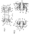
- FIG. 1 schematically shows two guide elements 1, 2, each consisting of two guide members 11, 12 and 21, 22, which are respectively arranged on both sides of a guide means 3 and 4 and connected by a fixing portion 15 and 25 with each other.
- the corresponding attachment section 15 or 25 passes through a guide opening 30 or 40 in the respective guide device 3 or 4.
- the guide openings 30, 40 of the guide devices 3, 4 can on the one hand (straight or curved) longitudinally extending guideways or guide slots form, so that the guide elements 1, 2 are guided as sliding guide perpendicular to the plane of the sheet slidably in the respective guide device 3 or 4.
- the guide openings 30, 40 of the guide means 3, 4 also each form a pivot bearing, so that the guide elements 1, 2 are designed as pivoting elements, which can be pivoted in the pivot bearing of the respectively associated guide means 3, 4.
- the two guide devices 3, 4 can thereby indirectly (indirectly) coupled to each other, that they are arranged on the two longitudinal sides of a unitary frame assembly (eg a seat support) of a motor vehicle seat.
- a unitary frame assembly eg a seat support
- the two guide elements 1, 2 are supported on both sides of the respective associated guide device 3 or 4 respectively via elastic means in the form of spring elements 16, 17 and 26, 27 (here represented schematically by compression springs) on abutment surfaces 31, 32 and 41, 42 of the respective Guide device 3, 4 from.
- These spring elements 16, 17 and 26, 27 are used to compensate for tolerances and the prevention of rattling noises.
- the direction along which the respective guide element 1 or 2 is supported on the respective associated guide device 3 or 4 via the corresponding spring elements 16, 17 or 26, 27 corresponds to the extension direction of the rigid or at least partially elastic connecting element V and extends in Transverse direction Q perpendicular to the direction of a possible movement of the guide elements 1, 2 in the associated guide means 3, 4 (guide direction).
- the reference numerals 16, 17; 26, 27 designated spring lines in each case symbolize elastically deformable means which structurally may be configured in any suitable form, such as separate spring elements or integrally formed on the guide members 11, 12 and 21, 22 elastic regions.
- the two spring elements 16, 17 which are associated with a first guide element 1 of the two guide elements 1, 2, a greater spring stiffness and a smaller maximum spring travel than the spring elements 26, 27 which are associated with the second guide element 2.
- the distance between the two guide members 11, 12 of the first guide member 1 and the associated stop surfaces 31, 32 of the corresponding guide means 3, between which the spring elements 16, 17 are supported smaller than in the case of the second guide member 2 with the two guide members 21st , 22 and the corresponding abutment surfaces 41, 42 of the associated guide means 4, where there are also the spring elements 26, 27 also respectively between one of the guide members 21, 22 and in each case an opposite stop surface 41, 42 of the guide means 4 supported.
- the two spring elements 16, 17 are already compressed so much in the assembled state, so have such a small remaining available maximum spring travel, that the first guide element 1 and the associated guide device 3 essentially form a fixed bearing, which only slight movements of the first guide element 1 in the transverse direction Q in the associated guide opening 30 allows.
- the second guide element 2 and the associated guide device 4 essentially form a floating bearing, in which substantial, ie, subjectively perceptible, movements of the corresponding guide element 2 along the transverse direction Q are possible by compressing the spring elements 26, 27 acting there in the transverse direction Q in the form of compression springs would.
- the two guide elements 1, 2 Since the first guide element 1 and the second guide element 2 are coupled to one another via the connecting element V, the two guide elements 1, 2 always move together both along the guide direction (perpendicular to the plane of the page) and along the transverse direction Q. A movement of the first guide element 1 , which leads to the maximum possible deformation of one of the local spring elements 16, 17, with respect to the second guide member 2 has a movement result, the only a fraction of the possible spring travel of there acting in the transverse direction Q spring elements 26, 27 exploits. Thus, as a rule, none of the two guide parts 21, 22 of the second guide element 2 engages in the transverse direction Q via the respective spring element 26 or 27 under the effect of operation of a motor vehicle in engagement with the associated abutment surface 41 or 42 of the associated guide device 4.
- the between the first guide member 1 and the abutment surfaces 31, 32 of the associated Guide device 3 existing range of motion (corresponding to the maximum possible additional compressibility of the local spring elements 16, 17) is chosen so that a relative movement of the first guide member 1 and the associated guide means 3 is not affected by a too much in the transverse direction Q braced bearing, but on the other hand only the smallest possible relative movements in the transverse direction Q should be possible.
- the second guide element 2 does not engage in the normal operation of a motor vehicle with the associated stops 41, 42 of the corresponding guide device 4 at all, but provides additional protection against excessive transverse movements in a crash case. If forces act in such a case, leading to damage of the first guide element 1 and / or the associated guide means 3, so that they can not prevent further transverse movement of the first guide member 1 relative to the associated guide means 3, then the second occur additionally Guide element 2 and the corresponding guide means 4 via the one guide member 21 and the corresponding stop 41 or the other guide member 22 and the corresponding stop 42 (by completely compressing one of the transverse acting there spring elements 26 or 27) engage with each other.
- each of the guide elements 1, 2 is also supported via spring elements Fz in the respective guide device 3 or 4, which cause a tolerance compensation and a damping of shocks perpendicular to the transverse direction Q.
- FIG. 2 shows a more detailed representation of an arrangement FIG. 1 , According to FIG. 2 is in each case on a guide part 11 of the first guide element 1 and on a guide part 21 of the second guide element 2, a bearing bush 13 and 23 arranged, with the corresponding guide element 1 or 2 in the guide opening 30 and 40 of the associated guide means 3, 4th intervenes.
- the two guide devices 3, 4 are coupled directly to one another via a connecting element V, while the two guide elements 1, 2 are indirectly connected to one another by attachment to a respective lateral structural part S of a motor vehicle subassembly.
- FIG. 2 recognizable that on a guide part 12 of the first guide member 1, the elastically deformable means 17 are provided only by the choice of a sufficiently deformable material for the main body of said guide member 12. There are no provided on the basis of their geometry elastic means. This is possible because the first guide member 1 should be able to perform only minor movements in the transverse direction Q relative to the associated guide device 3 anyway.
- the two the first and second guide element 1, 2 associated bearing bushes 13, 23 have a different size, wherein the respective fastening elements 15th , 25 adapted to this have different thread sizes.
- FIG. 2 shown arrangement with the schematically based FIG. 1
- the same reference numerals have been used for matching components. Therefore, to complete the description of the FIG. 2 to the appropriate explanations FIG. 1 directed.
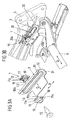
- FIG. 3a the first guide member 1 and the associated guide means 3 are explained in detail in a concrete embodiment.
- the first guide element 1 in the form of a sliding guide element therefore consists of two slide parts 11, 12 made of plastic, viewed in the transverse direction Q, arranged on both sides of a guide slot 30 of the associated guide means 3 and connected to each other by a clip connection 18, 19 passing through the guide slot 30.
- This clip connection is formed by latching openings 18 on a slide part 11 and associated clip hooks 19 on the other slider part 12.
- the clip hooks 19 pass through the Guide slot 30 of the guide device 3, as well as a bearing bush 13 of the first guide element 1, via which the guide element is mounted longitudinally displaceable in the guide slot 30.
- the clip hooks 19 and the associated latching openings 18 on the two slider parts 11, 12 of the first guide element 1 serve only to pre-fix the two slider parts 11, 12.
- the final fixation of the two slider parts 11, 12 to each other by means of a bolt 15, according to FIG. 3b is fastened by means of a nut 15a to a structural part S of a motor vehicle seat, namely a seat side part, while the two slide parts 11, 12 of the first guide element 1 are braced against each other.
- the integrally formed on the one, inner slide member 11 elastic means 16 in the form of an elastic portion are deformed so far that provided on this slide member 11 sliding 11a on a projecting in the direction of the slide member 11 of the guide means 3, the guide slot 30 limiting projection Abut 30a and at the same time in the transverse direction Q are only slightly spaced from the sliding part 11 associated stop surface 31 of the guide means 3.
- the sliding feet 11a When viewed in the transverse direction Q, the sliding feet 11a are set back relative to the elastic region 16 of the corresponding slider part 11, so that they can only engage with the associated stop 31 of the guide device 3 if the molded-on elastic means 16 are sufficiently deformed. A large part of this deformation takes place already during clamping of the two slide parts 11, 12 by means of the threaded bolt 15, so that in the assembled state of the guide element 1 only little play for a movement transverse to the guide direction R by further deformation of the said elastic means 16 remains. That is, there is only a small maximum exhaust travel available until the sliding feet 11a engage with the associated stop 31 of the guide means 3.
- the elastic means 17 acting in the transverse direction Q are formed by the elasticity of the material used for the basic body of this sliding part 12. Specially shaped resilient areas are not provided here. Furthermore, in the region of the bearing pin 13 on the outer slide member 12 spring means Fz formed, which serve as rattle to a support of the guide element 1 on the projection 30a of the guide slot 30 in a direction perpendicular to both the guide direction R and the transverse direction Q.
- one of the guide means 3 or 4 is then displaceably mounted by means of the associated guide slot 30 and 40 respectively.
- the two guide devices 3, 4 may for example be connected to a cushion support which serves to receive a seat cushion of the corresponding motor vehicle seat and which can be displaced along the guide direction R relative to the seat side parts S, which corresponds to an adjustability of the seat cushion depth.
- the corresponding guide arrangement can also be used for any other adjustment devices in motor vehicle seats or other vehicle parts, in which two guide elements spaced apart transversely to the guide direction of the respective adjustment movement (essentially rigidly) are coupled together and in each case in a guide device (eg in shape a guide slot or a pivot bearing) are feasible.
- a guide device eg in shape a guide slot or a pivot bearing
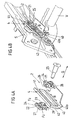
- FIG. 4a shows finally in greater detail the second guide element 2 of the guide assembly with the associated guide means 4.
- This also has an extended guide in the direction R guide slot 40 with an inwardly toward an inner slider 21 of the guide member 2 projecting, circumferential projection 40a.
- the second guide element 2 in the form of a sliding guide element likewise consists in turn of two slide parts 21, 22, namely an inner slide part 21 and an outer slide part 22, which can be provisionally connected to one another by means of the guide slide 40 by cross-coupling hooks 29 and associated latching openings 28.
- the final fixation is again by means of a threaded bolt 25, as in the case of in FIG. 3a shown first guide element 1 corresponding Through openings in the two slide parts 21, 22 and the guide slot 40 passes through and is screwed into the seat side part S.
- one of the two slide parts 21, 22 engages with a bearing bush 23 in the guide slot 40 of the guide device 4, wherein in the region of the bearing bush 23 on the corresponding slide member 22 perpendicular to both the guide direction R and the transverse direction Q acting spring elements Fz as rattle protection are formed.
- the acting in the transverse direction Q elastic means 26, 27 (elastic portions) of the two slide parts 21, 22 of the second guide element 2 are designed so that they are still substantially deformable even after a distortion of the slide parts 21, 22 by means of the threaded bolt 25, wherein the guide element 2 moves in the transverse direction Q relative to the guide device 4. This is a quasi-floating warehouse.
- the resilient means 26, 27 of the second guide element 2 acting in the transverse direction Q are arranged and dimensioned such that they are generally not compressed to the block under the action of transverse forces along said direction Q, if this is the case for the respectively corresponding spring-elastic section 16 or 17 of the first guide element 1 (cf. FIGS. 3a and 3b ) is already the case.
- the slide parts 21, 22 of the second guide element 2 can thus with the associated stops 41, 42 of the guide means 4 by complete deformation of the resilient means 26, 27 to block, ie until the meeting of the local transverse ribs 24 with the opposite regions of the respective resilient portion , only engage when the first guide member 1 and / or the associated guide means 3 have been so badly damaged that they can not fully absorb the forces acting in the transverse direction Q.
Landscapes
- Engineering & Computer Science (AREA)
- Aviation & Aerospace Engineering (AREA)
- Transportation (AREA)
- Mechanical Engineering (AREA)
- Seats For Vehicles (AREA)
Applications Claiming Priority (3)
| Application Number | Priority Date | Filing Date | Title |
|---|---|---|---|
| DE20318799U DE20318799U1 (de) | 2003-11-28 | 2003-11-28 | Vorrichtung zur Führung zwei zueinander verstellbarer Baugruppen eines Kraftfahrzeugs, insbesondere eines Kraftfahrzeugsitzes, entlang einer Führungsrichtung |
| DE102004007252A DE102004007252A1 (de) | 2003-11-28 | 2004-02-10 | Vorrichtung zur Führung zwei zueinander verstellbarer Baugruppen eines Kraftfahrzeugs, insbesondere eines Kraftfahrzeugsitzes, entlang einer Führungsrichtung |
| PCT/DE2004/002560 WO2005051701A2 (de) | 2003-11-28 | 2004-11-16 | Vorrichtung zur führung zwei zueinander verstellbarer baugruppen eines kraftfahrzeugs, insbesondere eines kraftfahrzeugsitzes, entlang einer führungsrichtung |
Publications (2)
| Publication Number | Publication Date |
|---|---|
| EP1704068A2 EP1704068A2 (de) | 2006-09-27 |
| EP1704068B1 true EP1704068B1 (de) | 2008-10-01 |
Family
ID=34635212
Family Applications (1)
| Application Number | Title | Priority Date | Filing Date |
|---|---|---|---|
| EP04802773A Expired - Lifetime EP1704068B1 (de) | 2003-11-28 | 2004-11-16 | Vorrichtung zur führung zwei zueinander verstellbarer baugruppen eines kraftfahrzeugs, insbesondere eines kraftfahrzeugsitzes, entlang einer führungsrichtung |
Country Status (6)
| Country | Link |
|---|---|
| US (1) | US7404537B2 (enExample) |
| EP (1) | EP1704068B1 (enExample) |
| JP (1) | JP4663652B2 (enExample) |
| DE (2) | DE102004007252A1 (enExample) |
| ES (1) | ES2314474T3 (enExample) |
| WO (1) | WO2005051701A2 (enExample) |
Families Citing this family (10)
| Publication number | Priority date | Publication date | Assignee | Title |
|---|---|---|---|---|
| DE102006056859B3 (de) * | 2006-12-01 | 2008-03-27 | Isringhausen Gmbh & Co. Kg | Gleiter für eine Sitzkissentiefeneinstellung eines Fahrzeugsitzes sowie Sitzkissentiefeneinstellung |
| DE102012006687B4 (de) | 2012-03-31 | 2022-12-29 | Adient Us Llc | Fahrzeugsitz |
| DE102012008822A1 (de) | 2012-05-07 | 2013-11-07 | GM Global Technology Operations LLC (n.d. Ges. d. Staates Delaware) | Verstellvorrichtung, Kraftfahrzeugsitz, Kraftfahrzeug und Verfahren hierzu |
| DE102012008821A1 (de) * | 2012-05-07 | 2013-11-07 | GM Global Technology Operations LLC (n.d. Ges. d. Staates Delaware) | Verstellvorrichtung, Fahrzeugsitz und Kraftfahrzeug sowie Verfahren hierzu |
| US20160083098A1 (en) * | 2014-09-24 | 2016-03-24 | Gulfstream Aerospace Corporation | Aircraft and seat track assemblies for vibration isolation of floor mounted components |
| US9399411B2 (en) * | 2014-12-22 | 2016-07-26 | Kawasaki Jukogyo Kabushiki Kaisha | Sliding structure for vehicle seat |
| JP6587749B2 (ja) * | 2016-07-28 | 2019-10-09 | 株式会社タチエス | 車両用シート |
| US11214374B2 (en) * | 2016-08-01 | 2022-01-04 | Gulfstream Aerospace Corporation | Seat track assemblies for vibration isolation of floor mounted components |
| DE102021116551A1 (de) * | 2021-06-25 | 2022-12-29 | Grammer Aktiengesellschaft | Fahrzeugsitz mit Sitztiefenverstellung |
| DE102022131302B4 (de) * | 2022-11-25 | 2024-12-12 | Grammer Aktiengesellschaft | Fahrzeugsitz und Verfahren zur werkzeuglosen Montage des Fahrzeugsitzes |
Family Cites Families (14)
| Publication number | Priority date | Publication date | Assignee | Title |
|---|---|---|---|---|
| IT212334Z2 (it) | 1987-07-29 | 1989-07-04 | Roltra Spa | Sedile motorizzato per veicoli |
| DE4330133A1 (de) * | 1993-09-06 | 1995-03-16 | Naue Johnson Controls Eng | Schienenführung für Fahrzeugsitze |
| DE19547034A1 (de) | 1995-12-15 | 1997-06-19 | Johnson Controls Naue Engineer | Sitzlängsverstellung |
| DE19624979C2 (de) * | 1996-06-22 | 1998-05-28 | Brose Fahrzeugteile | Vorrichtung zur translatorischen Verstellung eines Sitzteils, insbesondere zur Sitzkissenlängsverstellung von Kraftfahrzeugsitzen |
| USRE38845E1 (en) * | 1996-10-29 | 2005-10-25 | Honda Giken Kogyo Kabushiki Kaisha | Seat attachment structure for motor vehicles |
| EP0943484A3 (en) * | 1998-03-17 | 2000-08-16 | Ohi Seisakusho Co., Ltd. | Seat slide unit |
| JP2000006695A (ja) * | 1998-06-17 | 2000-01-11 | Toyotomi Kiko Co Ltd | 車両用シートの回転機構 |
| DE19904079C2 (de) | 1999-02-02 | 2001-10-18 | Ise Gmbh | Elektrischer Sitzversteller |
| DE19904224C1 (de) | 1999-02-03 | 2000-09-07 | Brose Fahrzeugteile | Verstellbares Sitzuntergestell für einen Fahrzeugsitz |
| DE10040594A1 (de) * | 2000-08-16 | 2002-03-07 | Keiper Gmbh & Co | Längsverstellvorrichtung für Kraftfahrzeuge |
| DE10046745C1 (de) | 2000-09-21 | 2002-02-14 | Keiper Recaro Gmbh Co | Fahrzeugsitz, insbesondere Kraftfahrzeugsitz |
| DE10113153C1 (de) * | 2001-03-14 | 2002-04-25 | Brose Fahrzeugteile | Sitzuntergestell für einen Fahrzeugsitz |
| DE10235086B4 (de) * | 2002-07-31 | 2009-10-29 | Johnson Controls Gmbh | Sicherheitseinrichtung für Fahrzeugsitze |
| KR100549200B1 (ko) * | 2004-02-23 | 2006-02-02 | 주식회사다스 | 자동차용 시트레일 탈락방지장치 |
-
2004
- 2004-02-10 DE DE102004007252A patent/DE102004007252A1/de not_active Withdrawn
- 2004-11-16 WO PCT/DE2004/002560 patent/WO2005051701A2/de not_active Ceased
- 2004-11-16 DE DE502004008177T patent/DE502004008177D1/de not_active Expired - Lifetime
- 2004-11-16 JP JP2006540155A patent/JP4663652B2/ja not_active Expired - Fee Related
- 2004-11-16 ES ES04802773T patent/ES2314474T3/es not_active Expired - Lifetime
- 2004-11-16 EP EP04802773A patent/EP1704068B1/de not_active Expired - Lifetime
- 2004-11-16 US US10/580,760 patent/US7404537B2/en not_active Expired - Fee Related
Also Published As
| Publication number | Publication date |
|---|---|
| ES2314474T3 (es) | 2009-03-16 |
| DE502004008177D1 (de) | 2008-11-13 |
| JP2007512169A (ja) | 2007-05-17 |
| WO2005051701A2 (de) | 2005-06-09 |
| WO2005051701A3 (de) | 2006-02-16 |
| US20070274616A1 (en) | 2007-11-29 |
| DE102004007252A1 (de) | 2005-06-23 |
| JP4663652B2 (ja) | 2011-04-06 |
| US7404537B2 (en) | 2008-07-29 |
| EP1704068A2 (de) | 2006-09-27 |
Similar Documents
| Publication | Publication Date | Title |
|---|---|---|
| EP2070761B1 (de) | Getriebebaueinheit einer Verstelleinrichtung eines Kraftfahrzeugs | |
| EP3501942B1 (de) | Lenksäulenbaugruppe | |
| EP3837150B1 (de) | Lenksäule für ein kraftfahrzeug | |
| EP1704068B1 (de) | Vorrichtung zur führung zwei zueinander verstellbarer baugruppen eines kraftfahrzeugs, insbesondere eines kraftfahrzeugsitzes, entlang einer führungsrichtung | |
| DE102016219104A1 (de) | Verstellvorrichtung einer Lordosenstütze oder eines Seitenwangenverstellers mit Spindelantrieb für ein Sitzelement eines Fahrzeugsitzes | |
| WO2017021383A1 (de) | Längsverstellvorrichtung für einen fahrzeugsitz | |
| DE112018000009T5 (de) | Längseinsteller für einen Fahrzeugsitz | |
| WO2012045778A2 (de) | Längsverstelleinrichtung für einen kraftfahrzeugsitz | |
| DE102021204486A1 (de) | Höhenverstelleinrichtung eines fahrzeugsitzes | |
| EP0813990B1 (de) | Vorrichtung zur translatorischen Verstellung eines Sitzteils, insbesondere zur Sitzkissenlängsverstellung von Kraftfahrzeugsitzen | |
| DE10008523B4 (de) | System zur kontinuierlichen Energieaufnahme durch Relativverschiebung | |
| WO2006024459A1 (de) | Lenksäulenanordnung | |
| DE102021202071A1 (de) | Lenksäulenanordnung für ein Kraftfahrzeug | |
| DE10260787B3 (de) | Vorrichtung zur Halterung eines Aggregats | |
| EP3934932A1 (de) | Längseinstellvorrichtung zur motorischen längseinstellung eines fahrzeugsitzes sowie fahrzeugsitz | |
| DE20318799U1 (de) | Vorrichtung zur Führung zwei zueinander verstellbarer Baugruppen eines Kraftfahrzeugs, insbesondere eines Kraftfahrzeugsitzes, entlang einer Führungsrichtung | |
| EP2374656B1 (de) | Fahrzeugsitzaufnahme | |
| DE202020107166U1 (de) | Fahrzeugsitz-Unterbau | |
| WO2018054977A1 (de) | Sitzschienenpaar für einen fahrzeugsitz | |
| DE102022122889B4 (de) | Achsstopper | |
| EP2661566B1 (de) | Lagereinheit für nutzfahrzeuge | |
| EP3665038A1 (de) | Längseinsteller für einen fahrzeugsitz | |
| DE102022117466A1 (de) | Fahrzeugsitz | |
| EP1147029B1 (de) | Längsverstellmechanismus für einen kraftfahrzeugsitz | |
| WO2024240583A1 (de) | Schienensystem für eine längsverstellung eines fahrzeugsitzes |
Legal Events
| Date | Code | Title | Description |
|---|---|---|---|
| PUAI | Public reference made under article 153(3) epc to a published international application that has entered the european phase |
Free format text: ORIGINAL CODE: 0009012 |
|
| 17P | Request for examination filed |
Effective date: 20060816 |
|
| AK | Designated contracting states |
Kind code of ref document: A2 Designated state(s): DE ES FR |
|
| RIN1 | Information on inventor provided before grant (corrected) |
Inventor name: FLETZBERGER, GUENTHER Inventor name: SCHMID, ANDREAS Inventor name: SCHWARZ, MARTIN Inventor name: SCHRIMPL, BERNHARD |
|
| DAX | Request for extension of the european patent (deleted) | ||
| RBV | Designated contracting states (corrected) |
Designated state(s): DE ES FR |
|
| GRAP | Despatch of communication of intention to grant a patent |
Free format text: ORIGINAL CODE: EPIDOSNIGR1 |
|
| RAP1 | Party data changed (applicant data changed or rights of an application transferred) |
Owner name: BROSE FAHRZEUGTEILE GMBH & CO. KG, COBURG |
|
| GRAS | Grant fee paid |
Free format text: ORIGINAL CODE: EPIDOSNIGR3 |
|
| GRAA | (expected) grant |
Free format text: ORIGINAL CODE: 0009210 |
|
| AK | Designated contracting states |
Kind code of ref document: B1 Designated state(s): DE ES FR |
|
| REF | Corresponds to: |
Ref document number: 502004008177 Country of ref document: DE Date of ref document: 20081113 Kind code of ref document: P |
|
| REG | Reference to a national code |
Ref country code: ES Ref legal event code: FG2A Ref document number: 2314474 Country of ref document: ES Kind code of ref document: T3 |
|
| PLBE | No opposition filed within time limit |
Free format text: ORIGINAL CODE: 0009261 |
|
| STAA | Information on the status of an ep patent application or granted ep patent |
Free format text: STATUS: NO OPPOSITION FILED WITHIN TIME LIMIT |
|
| 26N | No opposition filed |
Effective date: 20090702 |
|
| REG | Reference to a national code |
Ref country code: FR Ref legal event code: PLFP Year of fee payment: 12 |
|
| PGFP | Annual fee paid to national office [announced via postgrant information from national office to epo] |
Ref country code: ES Payment date: 20151014 Year of fee payment: 12 |
|
| REG | Reference to a national code |
Ref country code: FR Ref legal event code: PLFP Year of fee payment: 13 |
|
| REG | Reference to a national code |
Ref country code: FR Ref legal event code: PLFP Year of fee payment: 14 |
|
| PGFP | Annual fee paid to national office [announced via postgrant information from national office to epo] |
Ref country code: DE Payment date: 20171130 Year of fee payment: 14 |
|
| PG25 | Lapsed in a contracting state [announced via postgrant information from national office to epo] |
Ref country code: ES Free format text: LAPSE BECAUSE OF NON-PAYMENT OF DUE FEES Effective date: 20161117 |
|
| REG | Reference to a national code |
Ref country code: ES Ref legal event code: FD2A Effective date: 20180626 |
|
| REG | Reference to a national code |
Ref country code: FR Ref legal event code: PLFP Year of fee payment: 15 |
|
| PGFP | Annual fee paid to national office [announced via postgrant information from national office to epo] |
Ref country code: FR Payment date: 20181011 Year of fee payment: 15 |
|
| REG | Reference to a national code |
Ref country code: DE Ref legal event code: R119 Ref document number: 502004008177 Country of ref document: DE |
|
| PG25 | Lapsed in a contracting state [announced via postgrant information from national office to epo] |
Ref country code: DE Free format text: LAPSE BECAUSE OF NON-PAYMENT OF DUE FEES Effective date: 20190601 |
|
| PG25 | Lapsed in a contracting state [announced via postgrant information from national office to epo] |
Ref country code: FR Free format text: LAPSE BECAUSE OF NON-PAYMENT OF DUE FEES Effective date: 20191130 |