EP1695836B1 - Image forming apparatus - Google Patents
Image forming apparatus Download PDFInfo
- Publication number
- EP1695836B1 EP1695836B1 EP06250910A EP06250910A EP1695836B1 EP 1695836 B1 EP1695836 B1 EP 1695836B1 EP 06250910 A EP06250910 A EP 06250910A EP 06250910 A EP06250910 A EP 06250910A EP 1695836 B1 EP1695836 B1 EP 1695836B1
- Authority
- EP
- European Patent Office
- Prior art keywords
- image forming
- sheet
- forming apparatus
- recording
- feeding
- Prior art date
- Legal status (The legal status is an assumption and is not a legal conclusion. Google has not performed a legal analysis and makes no representation as to the accuracy of the status listed.)
- Ceased
Links
- 239000007788 liquid Substances 0.000 claims description 33
- 238000012423 maintenance Methods 0.000 claims description 29
- 238000007599 discharging Methods 0.000 claims description 25
- 238000011084 recovery Methods 0.000 claims description 22
- 230000007246 mechanism Effects 0.000 claims description 11
- 239000000976 ink Substances 0.000 description 51
- 230000015572 biosynthetic process Effects 0.000 description 21
- 238000010586 diagram Methods 0.000 description 16
- 238000010276 construction Methods 0.000 description 12
- 239000000758 substrate Substances 0.000 description 11
- 238000007639 printing Methods 0.000 description 10
- 238000001035 drying Methods 0.000 description 8
- 239000010410 layer Substances 0.000 description 6
- 230000015556 catabolic process Effects 0.000 description 4
- 239000003086 colorant Substances 0.000 description 4
- 238000006731 degradation reaction Methods 0.000 description 4
- 238000000034 method Methods 0.000 description 4
- 230000008569 process Effects 0.000 description 4
- 230000003287 optical effect Effects 0.000 description 3
- 230000000630 rising effect Effects 0.000 description 3
- 238000000926 separation method Methods 0.000 description 3
- 239000002344 surface layer Substances 0.000 description 3
- 238000004891 communication Methods 0.000 description 2
- 230000000694 effects Effects 0.000 description 2
- 230000005684 electric field Effects 0.000 description 2
- 238000005516 engineering process Methods 0.000 description 2
- 230000012447 hatching Effects 0.000 description 2
- 238000010438 heat treatment Methods 0.000 description 2
- 239000002245 particle Substances 0.000 description 2
- 238000012545 processing Methods 0.000 description 2
- 239000011347 resin Substances 0.000 description 2
- 229920005989 resin Polymers 0.000 description 2
- OKTJSMMVPCPJKN-UHFFFAOYSA-N Carbon Chemical compound [C] OKTJSMMVPCPJKN-UHFFFAOYSA-N 0.000 description 1
- 238000005452 bending Methods 0.000 description 1
- 230000005540 biological transmission Effects 0.000 description 1
- 230000000903 blocking effect Effects 0.000 description 1
- 238000007664 blowing Methods 0.000 description 1
- 229910052799 carbon Inorganic materials 0.000 description 1
- 238000004140 cleaning Methods 0.000 description 1
- 238000001816 cooling Methods 0.000 description 1
- 230000009977 dual effect Effects 0.000 description 1
- 238000001704 evaporation Methods 0.000 description 1
- 230000008020 evaporation Effects 0.000 description 1
- 125000001153 fluoro group Chemical group F* 0.000 description 1
- 239000011521 glass Substances 0.000 description 1
- 230000020169 heat generation Effects 0.000 description 1
- 230000006872 improvement Effects 0.000 description 1
- 230000010365 information processing Effects 0.000 description 1
- 239000000463 material Substances 0.000 description 1
- 238000012986 modification Methods 0.000 description 1
- 230000004048 modification Effects 0.000 description 1
- 230000035515 penetration Effects 0.000 description 1
- 230000010287 polarization Effects 0.000 description 1
- 238000001454 recorded image Methods 0.000 description 1
- 230000002040 relaxant effect Effects 0.000 description 1
- 239000002356 single layer Substances 0.000 description 1
- 229920001169 thermoplastic Polymers 0.000 description 1
- 239000004416 thermosoftening plastic Substances 0.000 description 1
- 230000005068 transpiration Effects 0.000 description 1
Images


Classifications
-
- B—PERFORMING OPERATIONS; TRANSPORTING
- B41—PRINTING; LINING MACHINES; TYPEWRITERS; STAMPS
- B41J—TYPEWRITERS; SELECTIVE PRINTING MECHANISMS, i.e. MECHANISMS PRINTING OTHERWISE THAN FROM A FORME; CORRECTION OF TYPOGRAPHICAL ERRORS
- B41J2/00—Typewriters or selective printing mechanisms characterised by the printing or marking process for which they are designed
- B41J2/005—Typewriters or selective printing mechanisms characterised by the printing or marking process for which they are designed characterised by bringing liquid or particles selectively into contact with a printing material
- B41J2/01—Ink jet
- B41J2/135—Nozzles
- B41J2/165—Prevention or detection of nozzle clogging, e.g. cleaning, capping or moistening for nozzles
- B41J2/16517—Cleaning of print head nozzles
- B41J2/1652—Cleaning of print head nozzles by driving a fluid through the nozzles to the outside thereof, e.g. by applying pressure to the inside or vacuum at the outside of the print head
-
- B—PERFORMING OPERATIONS; TRANSPORTING
- B41—PRINTING; LINING MACHINES; TYPEWRITERS; STAMPS
- B41J—TYPEWRITERS; SELECTIVE PRINTING MECHANISMS, i.e. MECHANISMS PRINTING OTHERWISE THAN FROM A FORME; CORRECTION OF TYPOGRAPHICAL ERRORS
- B41J2/00—Typewriters or selective printing mechanisms characterised by the printing or marking process for which they are designed
- B41J2/005—Typewriters or selective printing mechanisms characterised by the printing or marking process for which they are designed characterised by bringing liquid or particles selectively into contact with a printing material
- B41J2/01—Ink jet
- B41J2/17—Ink jet characterised by ink handling
- B41J2/175—Ink supply systems ; Circuit parts therefor
- B41J2/17503—Ink cartridges
- B41J2/17506—Refilling of the cartridge
- B41J2/17509—Whilst mounted in the printer
-
- B—PERFORMING OPERATIONS; TRANSPORTING
- B41—PRINTING; LINING MACHINES; TYPEWRITERS; STAMPS
- B41J—TYPEWRITERS; SELECTIVE PRINTING MECHANISMS, i.e. MECHANISMS PRINTING OTHERWISE THAN FROM A FORME; CORRECTION OF TYPOGRAPHICAL ERRORS
- B41J2/00—Typewriters or selective printing mechanisms characterised by the printing or marking process for which they are designed
- B41J2/005—Typewriters or selective printing mechanisms characterised by the printing or marking process for which they are designed characterised by bringing liquid or particles selectively into contact with a printing material
- B41J2/01—Ink jet
- B41J2/17—Ink jet characterised by ink handling
- B41J2/175—Ink supply systems ; Circuit parts therefor
- B41J2/17503—Ink cartridges
- B41J2/1752—Mounting within the printer
-
- B—PERFORMING OPERATIONS; TRANSPORTING
- B41—PRINTING; LINING MACHINES; TYPEWRITERS; STAMPS
- B41J—TYPEWRITERS; SELECTIVE PRINTING MECHANISMS, i.e. MECHANISMS PRINTING OTHERWISE THAN FROM A FORME; CORRECTION OF TYPOGRAPHICAL ERRORS
- B41J25/00—Actions or mechanisms not otherwise provided for
- B41J25/34—Bodily-changeable print heads or carriages
Definitions
- the present invention relates to image forming apparatuses and more particularly to an image forming apparatus that forms images by means of a recording head that ejects droplets of a recording liquid.
- a multifunctional image forming apparatus that uses the technology of ink-jet recording for the image forming part.
- a recording head that ejects droplets of a recording liquid called also as “ink”, is used for forming images on a medium, which is called also as “recording sheet”, “recording medium”, “recording object”, or the like, wherein such recording of images is called “recording”, “printing”, “reprography”, “character printing”, or the like.
- Patent Reference 1 discloses a conventional image forming apparatus that disposes an ink cartridge (ink tank) underneath a sheet discharging tray. Thereby, an ink is supplied to a sub-tank mounted upon a carriage together with a recording head from such an ink cartridge.
- ink cartridge ink tank
- Patent Reference 2 discloses a construction of image forming apparatus in which the medium formed with an image with a recording head is directly discharged to a discharging tray disposed inside the image forming apparatus.
- Patent Reference 3 discloses a construction that enables both face-down sheet discharging and face-up sheet discharging.
- the mechanism of maintenance generally includes a humidity maintenance cap that tightly covers the nozzle surface for preventing increase of viscosity of the recording liquid caused by evaporation of the recording liquid, a suction cap, serving sometimes also for the humidity maintenance cap, for sucking and discharging the viscous recording liquid from the nozzle, a wiper blade, called also as “cleaning blade”, “wiper”, “blade member”, or “blade”, for wiping away the recording liquid adhered to the nozzle surface, a dummy ejection part for conducting dummy ejection of the liquid droplets without forming images, and the like.
- the recording apparatus that employs serial scanning process that carries out formation of images on a sheet by causing the recording head to scan over the sheet in a main scanning direction in the state the recording head is mounted upon a carriage, it is practiced to dispose the maintenance and recovery mechanism at an end of the main scanning direction. Further, it is practiced to dispose the dummy ejection part on an end part of the main scanning direction for recovering the nozzle used for recording. Alternately, the maintenance and recovery mechanism is provided at both ends of the main scanning direction as set forth in Patent Reference 4.
- JP-A-07-047670 and JP-A-2002-192711 disclose image forming apparatus in which a cartridge loading part is disposed underneath a sheet discharge part and show the preamble of claim 1.
- the present invention provides an image forming apparatus that can reduce the size of the apparatus while at the same time securing sufficient time for drying the recording liquid on the image forming medium after image formation thereon.
- the present invention provides an image forming apparatus as defined in the appended claims.
- said engine part forms a unit detachable to and from said body of said image forming apparatus.
- said engine part includes a maintenance and recovery mechanism that maintains said recording head operational.
- said cartridge loading part is disposed at a front side of said body, said image forming apparatus including a part that generates heat such that said part is provided in said body at a rear side of said body.
- the part that generated heat is disposed opposite to said cartridge loading part.
- said part that generates heat is at least one of a power supply unit and a control board of said image forming apparatus.
- the image forming apparatus of the present invention it becomes possible to secure the time for drying the recording liquid on the recording sheet, on which image formation has been made, as the recording medium is fed by the medium discharging part disposed sideways to the image forming engine. Further, it becomes also possible to use the dead space underneath the medium discharging part by disposing the cartridge loading part therein.
- Figures 1 - 3 show an embodiment of the image forming apparatus according to the present invention, wherein Figure 1 shows the overall construction of the image forming apparatus, while Figure 2 is a plan view diagram showing the image forming part and sheet feeding part used with the image forming apparatus of Figure 1 . Further, Figure 3 shows a front view diagram of the sheet feeding part used with the image forming apparatus of the present invention.
- the image forming apparatus of the present invention includes an apparatus body 1, wherein the apparatus body 1 includes therein an image forming part 2 that forms an image on a recording sheet while feeding the recording sheet in a sub-scanning direction, and there is provided a sheet feeding part (sub-scanning feeding part) 3 also in the body 1 for feeding the recording sheet in the sub-scanning direction.
- the apparatus body 1 includes therein an image forming part 2 that forms an image on a recording sheet while feeding the recording sheet in a sub-scanning direction, and there is provided a sheet feeding part (sub-scanning feeding part) 3 also in the body 1 for feeding the recording sheet in the sub-scanning direction.
- the sheet feeding part 3 picks up a sheet 5 from a sheet feeding part 4 that includes a sheet feed cassette provided at a bottom part of the body 1 and feeds the sheet to a location facing the image forming part 2.
- the image forming part 2 ejects droplets of a liquid and achieves formation of a desired image on the sheet 5, and the sheet 5 thus recorded with the image is discharged to a discharge tray provided at a top part of the body 1 via a sheet discharge feed part 7 in the case of forming images only on a front side of the sheet 5.
- the sheet 5 is sent to a dual-side unit 10 provided at a bottom part of the body 1 from the sheet discharge feed part 7, wherein the sheet 5 is turned over by a switchback feeding and is fed again to the sheet feeding part 3 in the turned back state.
- recording of an image is conducted on the rear side of the sheet 5 by the image forming part 2, and the sheet 5 thus recorded with images at both sides is discharged to the discharge tray 8.
- the image forming apparatus of the present invention includes a scanner part 11 in the top part of the body 1 located above the discharge tray 8 as an input system for reading images, wherein the scanner part 11 is used for inputting image data for recording by the image forming part 2.
- the image reading part 11 includes an optical source 13 for illuminating the image to be scanned and a fixed optical system 15 including a mirror 14, wherein there is further provided a movable optical system 18 including mirrors 16 and 17, and reading of images is made from a manuscript placed on a contact glass 12.
- the image on the manuscript is converted to an image signal 20 disposed behind a lens 19, and the image signal thus formed is subjected to image processing after digitization. Recording of the image is then conducted on the recording sheet 5 by using the image data thus obtained as the print data.
- the image forming apparatus of Figure 1 is capable of receiving image data (print data) to be recorded by the image forming part 2 from an external host device such as an information processing apparatus including a personal computer or an image reading apparatus such as an external image scanner, or from a picturing apparatus such as a digital camera, via a cable or network.
- an external host device such as an information processing apparatus including a personal computer or an image reading apparatus such as an external image scanner, or from a picturing apparatus such as a digital camera, via a cable or network.
- an external host device such as an information processing apparatus including a personal computer or an image reading apparatus such as an external image scanner, or from a picturing apparatus such as a digital camera, via a cable or network.
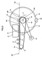
- the image forming part 2 of the image forming apparatus includes a carriage 23 held movably in a main scanning direction by way of a guide rod 21 shown in Figure 2 and a guide stay not illustrated, wherein carriage 23 is moved in the main scanning direction by a main scanning motor 27 via a timing belt 29 laid between a drive pulley 28A and a follower pulley 28B.
- the carriage 23 carries thereon a recording head 24 ejecting the droplets of respective colors, and the image forming part 2 is thus configured in the form of a shuttle type image forming engine that achieves image formation on a sheet 5 fed to the recording head 24 in a sheet feed direction (sub-scanning direction) by a sheet feeding part 3 by the carriage 23 moved in the main scanning direction while ejecting the liquid droplets from the recording head 24 thereon.
- the recording head 24 includes five liquid ejection heads, two of them (liquid ejection heads 24k1 and 24k2) ejecting black color inks (Bk), while the remaining liquid ejection heads 24c, 24m and 24y eject the inks of cyan (C), magenta (M) and yellow (Y), respectively.
- these liquid ejection heads are designated as "recording heads 24".
- the liquid ejection heads 24 are supplied with inks of the respective colors from the corresponding sub-tanks mounted upon the carriage 23.
- ink cartridges 26 loaded with inks of the respective colors, Bk, C, M and Y, detachably upon a cartridge loading part 30 from a front side of the body 1 of the image forming apparatus, and the inks of the respective colors are supplied to the corresponding sub-tanks 25 from the ink cartridges 26.
- the black ink is supplied from one ink cartridge 26 to two sub-tanks 25.
- a piezoelectric head that ejects ink droplets by using a piezoelectric element for the actuator means that applies a pressure to the ink inside an ink flow passage (pressure chamber) by causing deformation in a vibrator plate forming a wall of the ink flow passage.
- a thermal head that ejects ink droplets by the pressure of bubbles formed in the ink flow passage by heating the ink therein by way of a resistance heater.
- an electrostatic head that includes an electrode facing the vibrator plate and ejects ink droplets by causing a deformation in the vibrator plate by the electrostatic force induced between the vibrator plate and the electrode such that the volume of the ink flow passage is changed.
- a maintenance and recovery unit 121 that maintains and recovers operational state for the nozzles of the recording head 24 such that the maintenance and recovery unit 121 is disposed in a non-printing region at an end of the main scanning direction of the carriage 23.
- this maintenance and recovery unit 121 includes: five humidity maintenance caps 122k2, 122k1, 122c, 122m and 122y (collectively designated as “humidity maintenance caps 122") respectively for the five recording heads 24; a suction cap 123; a wiper blade 124 for wiping the nozzle surface of the recording head 24, and a dummy ejection part 125 for receiving dummy ejection of the liquid droplets conducted for the purpose of maintenance of the recording head. This dummy ejection does not contribute to image recording.
- dummy ejection part 126 for receiving dummy ejection of the liquid droplets from the five recording heads 24 not contributing to the image formation.
- This dummy ejection part 126 is formed with five openings 127k2, 127k1, 127c, 127m and 127y in correspondence to the recording head 24, wherein the openings 127k2, 127k1, 127c, 127m and 127y are also designated collectively as "opening 127".
- the sub-scanning feeding part 3 includes: an endless feeding belt 31 laid between a feeding roller 32 functioning as a drive roller and a follower roller 33 functioning as a tension roller, the endless belt 31 feeding a sheet 5 fed from a downward direction by deflecting the direction of feeding by about 90 degrees such that the sheet 5 is fed in a manner facing the image forming part 2; a charging roller supplied with high AC.
- this feeding belt 31 of the sub-scanning part 3 circles around in the sheet feeding direction (sub-scanning direction) of Figure 2 with rotation of the feeding roller 32 caused by a sub-scanning motor 131 via a timing belt 132 and a timing roller 133.
- the feeding belt 31 has a two-layer structure comprising: a front surface layer functioning as the sheet suction surface and formed of a pure resin layer not subjected to resistance control such as a pure thermoplastic fluoro resin; and a rear surface layer of the same material as the front surface layer but subjected to resistance control by using carbon (medium resistance layer or grounding layer).
- the belt 31 is not limited to such a two-layer construction and it may have three or more layers or it may have a single-layer structure.
- the feeding roller 32 has a shaft 32a provided with a code wheel 137 of high resolution, wherein a photo sensor 138 of transmission type cooperates with the code wheel 137 for detecting the slits provided in the code wheel 137.
- the code wheel 137 and the photo sensor 138 constitute a rotary encoder.
- the sheet feeding part 4 comprises:
- the sheet discharge feed part 7 comprises:
- the feeding path of the sheet 5 between the lower guide 73 and the upper guide 74 is designated as a feeding path 70, wherein it should be noted that the feeding path 70 is provided with a length such that it takes a time sufficient for the image formed on the recording sheet 5 is dried to the degree that rubbing of the image does not take plate when the sheet is discharged along the feeding path 70.
- a switching mechanism 60 for switching the feeding path of the sheet 5 between the first path 81 for discharging the sheet to the discharging tray 8, a second path 82 used for discharging the sheet to a straight discharging tray 181, and a third path (dual-side discharging path) 83 for sending the sheet 5 to the dual-side unit 10.
- the third path 83 extends vertically at the lateral side of the main body 1 of the image forming apparatus, and the sheet diverted by the switching mechanism 60 is fed to the dual-side unit 10 vertically along the path 83. Further, in order to feed the sheet 5 fed into the vertical sheet feed path 83, there are provided an inlet roller pair 91 and an outlet roller pair 92. Further, there is provided a guide plate 84 at the lateral part of the body 1 of the image forming apparatus for forming the vertical sheet feed path 83.
- the dual-side unit 10 includes a horizontal take-up sheet feed path 90a for taking up and feeding the sheet 5 fed from the vertical sheet feed path 83 in a horizontal direction and a switchback feed path 90b.
- the horizontal take-up sheet feed path 90a comprises dual-side feed roller pairs 93
- the switchback feed path 90b includes a dual-side exit roller 94 formed of a reverse roller for re-feeding the sheet 5 fed from the take-up sheet feed path 90a after turning back and three dual-side feed roller pairs 95.
- a movable diverting plate 96 in a manner to swing between two a first state shown in Figure 1 by a continuous line for switchback and a second state shown in Figure 1 by a broken line for re-feeding.
- the sheet 5 fed out from the dual-side unit 10 is forwarded to the resist roller 44 via the feed roller 48.
- a movable open/close guide plate 110 shown in Figure 1 for forming a loop (relaxing) in the sheet 5 between the location of the feed roller 32 and the pressurizing roller 36 of the sub-scanning feed part 3 and the resist roller 44 and for preventing formation of back tension in the sheet 5 as the sheet 5 is fed from the manual feed tray 46 or the dual-side unit 10 and transported by the resist roller 44.
- this open/close guide plate 110 guides the sheet 5, when sending the sheet 5 from the resist roller 44 to the sub-scanning feed part 3, by swinging in the direction of arrow from the illustrated state, while the open/close guide plate 110 returns to the illustrated state with the timing when the sheet 5 has reached the sub-scanning feed part 3 and allows formation of the loop.
- a manual feed tray 141 shown in Figure 1 in a manner of movable between a closed state and opened state on a lateral side of the apparatus body 1 for enabling manual feeding of a sheet, wherein the manual feed tray 141 is opened to the state shown in Figure 1 by a tow-dotted line when such manual feeding of a sheet is to be conducted.
- the sheet 5 manually fed from the tray 141 is guided by the top surface of the open/close guide plate 110 and enters straight to the path between the feed roller 32 and the pressure roller 36 of the sub-scanning feed part 3.
- the body 1 of the image forming apparatus is provided with a straight discharge tray 181 at another lateral side of the apparatus body 1 also in a manner movable between a closed sate and opened state.
- a straight discharge tray 181 at another lateral side of the apparatus body 1 also in a manner movable between a closed sate and opened state.
- this sheet feed mode can be used also for ordinary sheets such as ordinary paper.
- the charging roller 34 is applied with a high AC voltage of the form of positive and negative rectangular pulses from an AC bias source not illustrated, and with this, there are induced positive and negative charges on the insulating front surface of the feed belt 31 alternately in the form of bands with a predetermined bandwidth. Thereby, there is induced non-uniform electric field.
- the sheet 5 is fed intermittently with the feed belt 31 and recording of images is achieved on the surface of the sheet 5 by the droplets of the liquid ejected from the recording head 24 in accordance with the print data.
- the sheet 5 thus recorded with the image is then separated from the feed belt 31 by engaging the separation nail 38 with the tip end of the sheet 5, and the sheet 5 thus separated is discharged to any of the discharge tray 8 or the straight discharge tray 181 or fed to the dual-side unit 10 for image recording on the rear side.
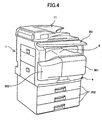
- Figure 4 shows the image forming apparatus in an oblique view
- Figure 5 is a front view diagram for explaining the layout of various components of the image forming apparatus
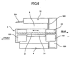
- Figure 6 is a schematic diagram of the image forming apparatus as viewed from a right direction
- Figure 7 is a schematic plan view of the image forming apparatus.
- Figure 8 shows the engine unit in an oblique view.
- the image forming apparatus integrates the image forming part 2 and the sub-scanning feed part 3 in the form of an engine unit (engine part) 230 as shown in Figure 8 , and engine unit 230 is disposed inside the apparatus body 1 together with the sheet feed part 4 and the sheet discharge feed part 7, wherein the image reading part 11 is disposed at the top part of the apparatus body 1 and the sheet discharge part (discharge tray) 8 is provided in the upper part of the apparatus body 1 for discharging the sheet.
- engine unit 230 is disposed inside the apparatus body 1 together with the sheet feed part 4 and the sheet discharge feed part 7, wherein the image reading part 11 is disposed at the top part of the apparatus body 1 and the sheet discharge part (discharge tray) 8 is provided in the upper part of the apparatus body 1 for discharging the sheet.
- an operational panel 201 above the discharge tray 8 for providing instructions to the various parts of the image forming apparatus including the image reading part 11 and for displaying various information, wherein the operational panel 201 is provided in a manner that the tilt angle thereof can be adjusted.
- the operational panel 201 is provided in a manner that the tilt angle thereof can be adjusted.
- optional sheet feed trays 202 in the lower part of the apparatus body by replacing the dual-side unit 10 in the form that the plural sheet feed trays 202 are stacked with each other.
- a right front cover 301 in a manner that the right front cover 301 is opened and closed, wherein the cover 301 is provided for mounting and dismounting the engine unit 230, in which the image forming part 2 and the sub-scanning feed part 3 are integrated, to and from the apparatus body 1.
- a left front cover 302 capable of being opened and closed for enabling replacement of the ink cartridges 26 with regard t the cartridge loading part 30.
- the right front cover 301 bulges more in the front direction as compared with the left front cover 302 in correspondence to the dummy ejection part 126 of the engine unit provided in correspondence to this part as shown in Figure 7 (see also Figure 2 ), and the left front cover 301 corresponding to the ink cartridges 26 is receded relatively to the right front cover 203. With this, the area occupied by the apparatus body 1 is reduced.
- the engine unit 230 is disposed at the right side in the apparatus body 1 when viewed from the front direction, and the sheet discharge feed part 7 having the feed path 70, which feeds the sheet 5 straight after image formation by the engine unit 230, is disposed sideways to the engine unit 230. Further, the cartridge loading part 30 for loading the ink cartridge 26 detachably is disposed underneath the sheet discharge feed part 7.
- the straight feed path 70 of the sheet discharge feed part 7 such that the sheet 5 is fed straight inside the apparatus main body 1 after image formation with the engine unit 230, it becomes possible to secure sufficient time for the ink applied to the sheet 5 is dried after imaged formation, before the sheet 5 is discharged to the discharge tray 8 in the turned-over state, and it becomes possible to eliminate the problem of degradation of image quality caused by rubbing of still wet images.
- the present invention successfully avoids this problem by providing the sheet discharge feed part 7 that feeds the sheet straight after image formation by the image forming unit in the state that the image formation surface faces in the upward direction, it becomes possible to secure the time needed for drying the recording liquid applied upon the sheet surface. Thereafter, the sheet is turned over for discharging upon the tray 8. With such operation, applied to the dried sheet, there is caused no problem of degradation of image quality.
- the space underneath the sheet discharge feed part 7 is utilized efficiently, and it becomes possible to reduce the space of the apparatus body 1 in the front-rear direction.
- the scanning region of the carriage 23 becomes inevitably larger than the width of the normally used sheet in view of the need of providing the maintenance and recovery unit 121 and the dummy ejection part 126 for maintaining and recovering the function of the recording head 24 as noted before.
- the carriage 23 With the construction of disposing the carriage 23 with an orientation such that scanning is made in the front-rear direction of the apparatus main body 1, it is inevitable to dispose the maintenance and recovery unit 121 and the dummy ejection part 126 in the front-rear direction, such that the maintenance and recovery unit 121 is disposed at the rear side and the dummy ejection part 126 is disposed at the front side, for example.
- the image forming apparatus is the one having the construction in which the ink tanks are mounted upon the carriage 23, there is no need of providing the loading part for loading the ink cartridges at the front side of the apparatus body 1, while with the image forming apparatus of the present invention that uses sub-tanks, there is a need of providing the loading part for loading the ink cartridges at the front side of the apparatus body 1.
- this ink cartridge loading part is disposed underneath the engine unit 230, it will be noted that the height of the apparatus body 1 becomes unnecessarily large particularly with the construction in which the maintenance and recovery unit 121 or the dummy ejection part 126 is disposed at respective sides of the carriage main scanning direction. Further, in the case of the image forming apparatus in which the engine unit 230 is detachable with regard to the apparatus main body 1 as in the present case, it is not possible to dispose the ink cartridge loading part at the front side of the engine unit 230.
- the ink cartridge loading part 30 By disposing the ink cartridge loading part 30 in the space underneath the sheet discharge feed part 7 at the lateral side of the engine unit 230 inside the apparatus main body 1 as viewed from the front direction of the apparatus body 1 as shown in Figure 5 , it becomes possible to dispose the ink cartridge loading part 30 without increasing the height or lateral size of the apparatus body 1. Further, as shown in Figure 7 , it becomes possible to reduce the size of the apparatus body 1 in the front-rear direction by disposing the ink cartridge loading part 30 to be located inside the sheet feed path as viewed in the plan view. Further, such a construction can use the space underneath the sheet discharge feed part 7 by providing the sheet discharge feed part 7 for securing the time needing for drying the applied liquid.
- the circuitry part 400 that generates heat is disposed at the opposite, rear side of the apparatus body 1 as shown in Figures 7 and 5 .
- the circuitry part 400 that includes components generating heat is disposed at the rear side of the apparatus body 1 opposite to the cartridge loading part 30 and at the lateral side of the maintenance and recovery unit 121 for suppressing the effect of heat upon the maintenance and recovery unit 121 of the image forming part 2.
- the circuitry part 400 includes at least the power supply unit and control substrate that tend to generate substantial heat.
- the engine unit 230 integrates the image forming part 2 and the sub-scanning part 3 for facilitating loading and unloading to and from the apparatus body 1 for improved easiness of maintenance.
- the ink cartridge loading part 30 includes a frame 260 on which the ink cartridges 26 are loaded and a supply mechanism 261 for feeding out the ink in the ink cartridges 26 for supplying the ink to the sub-tanks 25 from the ink cartridges 26 mounted upon the carriage 23, wherein the supply mechanism 261 feeds the ink to the sub-tanks 25 on the carriage 23 by way of five tubes 262.
- the frame 260 of the ink cartridge loading part 30 is fixed upon the frame 231 of the engine unit 230, and the ink cartridge 26 and the engine unit 320 are integrated to form a unit.
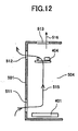
- Figure 9 is an oblique view showing the rear part while Figure 10 is a plan view.
- Figure 11 is a schematic side view of the rear part of the apparatus body 1.
- the maintenance and recovery unit 121 is disposed between a rear cover 501 and a side plate 502 of the apparatus body 1, and the side plate 502 is formed with an opening 503 for mounting and dismounting the engine unit 230.
- a space 504 at the lateral side of the maintenance and recovery unit 121 such that the space 504 is not provided with a component extending in the vertical direction.
- the circuitry part 400 is disposed at the under side and lateral side of this space 504.
- a power supply unit 401 that constitutes the circuitry part 400 and includes components 401a that generates heat is disposed at the under side to the lateral side of the space 504 where no component is provided. Further, there are provided a control substrate 402 carrying thereon a control part for controlling the overall operation of the image forming apparatus and an image forming substrate 403 carrying thereon an engine control part (image formation control part) that controls each part of the engine unit 230 in the space 504 over the power supply unit 401 so as to extend vertically along the space 504. Further, a drive substrate 404 carrying a drive circuit of motors is disposed over the maintenance and recovery unit 121.
- a lower opening 511 (shown with hatching in Figure 9 ) on the rear cover 501 at a lower lateral part thereof so as to provide communication between the space 504 and the exterior of the apparatus body 1
- an upper opening 512 (shown with hatching in Figure 9 ) on the rear cover 501 at an upper lateral part thereof so as to provide communication between the space 504 and the exterior of the apparatus body 1.
- the lower opening 511 is formed with a width (lateral direction of Figure 7 ) generally equal to the width of the power supply unit 401
- the upper opening 512 is formed with a width generally equal to the width of the apparatus body 1.
- the power supply unit 401 that includes heat-generating elements such as coils and transistors is disposed right underneath the space 504, and the control substrate 402 and the image forming substrate 403 are disposed so as to extend vertically along the space 504.
- the space 504 functions as a chimney and it was in fact confirmed that there is induced a fast air flow streaming in the upward direction by the heat generated by the power supply unit 401 located at the bottom part of the body 1.
- blowing means such as a fan.
- the carriage 23 is moved back and forth in the direction of arrows shown in Figure 6 for formation of the images, and thus, the carriage 23 moves in and out a chamber 505 defined in the apparatus body 1 by the frame (side plate) 502 and the rear cover 501, wherein negative pressure and positive pressure induced in the chamber 505 with the in/out movement of the carriage 23 provides turbulence in the air inside the chamber 505. Air flow induced with such air turbulence also contributes to the cooling of the circuitry part 400.
- the present invention is based on Japanese priority application No.2005-048436 filed on February 24, 2005.
Landscapes
- Ink Jet (AREA)
- Accessory Devices And Overall Control Thereof (AREA)
Applications Claiming Priority (1)
| Application Number | Priority Date | Filing Date | Title |
|---|---|---|---|
| JP2005048436A JP4738838B2 (ja) | 2005-02-24 | 2005-02-24 | 画像形成装置 |
Publications (2)
| Publication Number | Publication Date |
|---|---|
| EP1695836A1 EP1695836A1 (en) | 2006-08-30 |
| EP1695836B1 true EP1695836B1 (en) | 2010-10-27 |
Family
ID=36426411
Family Applications (1)
| Application Number | Title | Priority Date | Filing Date |
|---|---|---|---|
| EP06250910A Ceased EP1695836B1 (en) | 2005-02-24 | 2006-02-21 | Image forming apparatus |
Country Status (5)
| Country | Link |
|---|---|
| US (2) | US7497568B2 (zh) |
| EP (1) | EP1695836B1 (zh) |
| JP (1) | JP4738838B2 (zh) |
| CN (1) | CN100572067C (zh) |
| DE (1) | DE602006017762D1 (zh) |
Families Citing this family (9)
| Publication number | Priority date | Publication date | Assignee | Title |
|---|---|---|---|---|
| JP5078550B2 (ja) * | 2007-10-29 | 2012-11-21 | 株式会社リコー | 画像形成装置 |
| JP4941334B2 (ja) * | 2008-01-30 | 2012-05-30 | ブラザー工業株式会社 | インクジェット記録装置 |
| JP5174724B2 (ja) * | 2009-03-12 | 2013-04-03 | 京セラドキュメントソリューションズ株式会社 | 画像形成装置 |
| CN102198751A (zh) * | 2010-03-23 | 2011-09-28 | 株式会社东芝 | 喷墨图像形成装置和喷墨图像形成方法 |
| WO2013128923A1 (ja) * | 2012-02-28 | 2013-09-06 | セイコーエプソン株式会社 | インクジェット記録装置 |
| US8899741B2 (en) * | 2013-01-25 | 2014-12-02 | Hewlett-Packard Development Company, L.P. | Printer including duplex media path |
| US10434805B2 (en) * | 2015-04-17 | 2019-10-08 | Hewlett-Packard Development Company, L.P. | Discharge of heated fluid from a printer |
| JP7434924B2 (ja) * | 2020-01-23 | 2024-02-21 | セイコーエプソン株式会社 | 記録装置 |
| JP7443921B2 (ja) | 2020-05-07 | 2024-03-06 | ブラザー工業株式会社 | 画像記録装置 |
Family Cites Families (28)
| Publication number | Priority date | Publication date | Assignee | Title |
|---|---|---|---|---|
| US4643448A (en) * | 1985-08-05 | 1987-02-17 | Michael Ladney | Energy absorbing steering assembly |
| JP3175769B2 (ja) | 1989-08-29 | 2001-06-11 | キヤノン株式会社 | インクジェット記録装置および該記録装置に用いるインクカートリッジ |
| JPH0789161A (ja) * | 1993-04-28 | 1995-04-04 | Canon Inc | 画像形成装置および画像形成方法 |
| JPH0747670A (ja) * | 1993-08-06 | 1995-02-21 | Canon Aptecs Kk | プリンタ |
| JP3516733B2 (ja) * | 1994-10-12 | 2004-04-05 | 株式会社リコー | 画像形成装置 |
| JPH08164636A (ja) * | 1994-12-13 | 1996-06-25 | Canon Inc | 複合画像形成装置 |
| EP1324151B1 (en) * | 1997-01-31 | 2008-02-20 | Seiko Epson Corporation | Developing unit |
| US6151037A (en) * | 1998-01-08 | 2000-11-21 | Zebra Technologies Corporation | Printing apparatus |
| US6139140A (en) * | 1998-09-29 | 2000-10-31 | Hewlett-Packard Company | Inkjet printing apparatus with media handling system providing small bottom margin capability |
| JP4508329B2 (ja) | 1999-01-14 | 2010-07-21 | キヤノン株式会社 | 印刷装置及びその制御方法及び記憶媒体 |
| JP3763726B2 (ja) * | 1999-07-14 | 2006-04-05 | キヤノンファインテック株式会社 | インクジェット記録装置 |
| JP3755867B2 (ja) | 2000-02-29 | 2006-03-15 | キヤノン株式会社 | 画像形成装置および記録媒体 |
| US6397023B1 (en) * | 2000-06-06 | 2002-05-28 | Hewlett-Packard Company | Techniques for achieving correct order in printer output |
| JP2002192711A (ja) | 2000-12-26 | 2002-07-10 | Canon Inc | インクジェット記録装置 |
| US6582039B2 (en) | 2001-07-24 | 2003-06-24 | Hewlett-Packard Developement Company, L.P. | Combination color inkjet and laser image-printing device with dual paper-picking mechanism and method of implementing same |
| US6682190B2 (en) * | 2002-01-31 | 2004-01-27 | Hewlett-Packard Development Company, L.P. | Controlling media curl in print-zone |
| JP4145185B2 (ja) * | 2002-04-16 | 2008-09-03 | 株式会社リコー | 画像形成装置及びネットワークシステム |
| JP2004009404A (ja) | 2002-06-05 | 2004-01-15 | Ricoh Co Ltd | インクジェット記録装置 |
| JP4140300B2 (ja) * | 2002-07-23 | 2008-08-27 | ブラザー工業株式会社 | インクカートリッジ、および、そのインク充填方法 |
| JP2004188964A (ja) * | 2002-11-25 | 2004-07-08 | Konica Minolta Holdings Inc | インクジェットプリンタ及びインクジェットプリンタの画像記録方法 |
| JP2004255679A (ja) * | 2003-02-25 | 2004-09-16 | Ricoh Co Ltd | インクジェット記録装置 |
| JP2004260618A (ja) * | 2003-02-26 | 2004-09-16 | Seiko Epson Corp | プリンタ |
| JP2004284084A (ja) | 2003-03-19 | 2004-10-14 | Ricoh Co Ltd | 液体吐出装置の回復方法及び画像形成装置 |
| JP3958258B2 (ja) * | 2003-07-24 | 2007-08-15 | キヤノン株式会社 | 外部装置及び画像形成装置 |
| JP2005048436A (ja) | 2003-07-28 | 2005-02-24 | Ntt Power & Building Facilities Inc | 制振用ロープの設置方法 |
| JP2005089125A (ja) | 2003-09-18 | 2005-04-07 | Ricoh Co Ltd | 画像形成装置 |
| JP4260059B2 (ja) * | 2004-05-11 | 2009-04-30 | 株式会社リコー | 画像形成装置 |
| JP2011025487A (ja) * | 2009-07-24 | 2011-02-10 | Kyocera Mita Corp | 記録ヘッドの回復装置及びそれを備えたインクジェット記録装置 |
-
2005
- 2005-02-24 JP JP2005048436A patent/JP4738838B2/ja not_active Expired - Fee Related
-
2006
- 2006-02-21 EP EP06250910A patent/EP1695836B1/en not_active Ceased
- 2006-02-21 US US11/359,861 patent/US7497568B2/en active Active
- 2006-02-21 DE DE602006017762T patent/DE602006017762D1/de active Active
- 2006-02-24 CN CNB2006100673647A patent/CN100572067C/zh not_active Expired - Fee Related
-
2009
- 2009-01-13 US US12/319,878 patent/US8152259B2/en not_active Expired - Fee Related
Also Published As
| Publication number | Publication date |
|---|---|
| JP4738838B2 (ja) | 2011-08-03 |
| US7497568B2 (en) | 2009-03-03 |
| US8152259B2 (en) | 2012-04-10 |
| DE602006017762D1 (de) | 2010-12-09 |
| EP1695836A1 (en) | 2006-08-30 |
| JP2006231657A (ja) | 2006-09-07 |
| CN1824505A (zh) | 2006-08-30 |
| CN100572067C (zh) | 2009-12-23 |
| US20090128597A1 (en) | 2009-05-21 |
| US20060187245A1 (en) | 2006-08-24 |
Similar Documents
| Publication | Publication Date | Title |
|---|---|---|
| US8152259B2 (en) | Image forming apparatus | |
| JP4726155B2 (ja) | 画像形成装置 | |
| EP1695831B1 (en) | Image forming apparatus | |
| US7775619B2 (en) | Image forming apparatus | |
| JP4726156B2 (ja) | 画像形成装置 | |
| US7425064B2 (en) | Image-forming device | |
| JP2009160854A (ja) | 画像形成装置 | |
| JP2006256864A (ja) | 画像形成装置 | |
| US7434928B2 (en) | Image forming apparatus | |
| JP2007144826A (ja) | インクジェット記録装置 | |
| US8727494B2 (en) | Droplet ejection device and image forming apparatus | |
| US7367667B2 (en) | Image forming apparatus with conveying part arranged to allow drying | |
| KR100717049B1 (ko) | 교체형 스캐닝 유닛을 구비하는 하이브리드 잉크젯화상형성장치 | |
| JP4710223B2 (ja) | 液体吐出カートリッジ、液体吐出装置及び液体吐出方法 | |
| US20240001676A1 (en) | Liquid discharging apparatus | |
| JP7059562B2 (ja) | シート搬送装置、及び画像形成装置 | |
| JP2005319587A (ja) | 液体収能容器、インクジェット記録装置、及び画像形成装置 | |
| JP2011005728A (ja) | 画像形成装置 | |
| JPH11105309A (ja) | 記録ヘッドおよびそれを用いたインク記録装置 | |
| JP2000309448A (ja) | 読取記録装置 | |
| JP2008087240A (ja) | インクジェット記録装置、及びインクジェット記録装置のヘッドクリーニング方法 |
Legal Events
| Date | Code | Title | Description |
|---|---|---|---|
| PUAI | Public reference made under article 153(3) epc to a published international application that has entered the european phase |
Free format text: ORIGINAL CODE: 0009012 |
|
| 17P | Request for examination filed |
Effective date: 20060318 |
|
| AK | Designated contracting states |
Kind code of ref document: A1 Designated state(s): AT BE BG CH CY CZ DE DK EE ES FI FR GB GR HU IE IS IT LI LT LU LV MC NL PL PT RO SE SI SK TR |
|
| AX | Request for extension of the european patent |
Extension state: AL BA HR MK YU |
|
| AKX | Designation fees paid |
Designated state(s): DE ES FR GB IT NL |
|
| GRAP | Despatch of communication of intention to grant a patent |
Free format text: ORIGINAL CODE: EPIDOSNIGR1 |
|
| GRAS | Grant fee paid |
Free format text: ORIGINAL CODE: EPIDOSNIGR3 |
|
| GRAA | (expected) grant |
Free format text: ORIGINAL CODE: 0009210 |
|
| AK | Designated contracting states |
Kind code of ref document: B1 Designated state(s): DE ES FR GB IT NL |
|
| REG | Reference to a national code |
Ref country code: GB Ref legal event code: FG4D |
|
| REF | Corresponds to: |
Ref document number: 602006017762 Country of ref document: DE Date of ref document: 20101209 Kind code of ref document: P |
|
| REG | Reference to a national code |
Ref country code: NL Ref legal event code: VDEP Effective date: 20101027 |
|
| PG25 | Lapsed in a contracting state [announced via postgrant information from national office to epo] |
Ref country code: NL Free format text: LAPSE BECAUSE OF FAILURE TO SUBMIT A TRANSLATION OF THE DESCRIPTION OR TO PAY THE FEE WITHIN THE PRESCRIBED TIME-LIMIT Effective date: 20101027 |
|
| PG25 | Lapsed in a contracting state [announced via postgrant information from national office to epo] |
Ref country code: ES Free format text: LAPSE BECAUSE OF FAILURE TO SUBMIT A TRANSLATION OF THE DESCRIPTION OR TO PAY THE FEE WITHIN THE PRESCRIBED TIME-LIMIT Effective date: 20110207 |
|
| PLBE | No opposition filed within time limit |
Free format text: ORIGINAL CODE: 0009261 |
|
| STAA | Information on the status of an ep patent application or granted ep patent |
Free format text: STATUS: NO OPPOSITION FILED WITHIN TIME LIMIT |
|
| 26N | No opposition filed |
Effective date: 20110728 |
|
| REG | Reference to a national code |
Ref country code: DE Ref legal event code: R097 Ref document number: 602006017762 Country of ref document: DE Effective date: 20110728 |
|
| PG25 | Lapsed in a contracting state [announced via postgrant information from national office to epo] |
Ref country code: IT Free format text: LAPSE BECAUSE OF FAILURE TO SUBMIT A TRANSLATION OF THE DESCRIPTION OR TO PAY THE FEE WITHIN THE PRESCRIBED TIME-LIMIT Effective date: 20101027 |
|
| REG | Reference to a national code |
Ref country code: FR Ref legal event code: PLFP Year of fee payment: 11 |
|
| REG | Reference to a national code |
Ref country code: FR Ref legal event code: PLFP Year of fee payment: 12 |
|
| REG | Reference to a national code |
Ref country code: FR Ref legal event code: PLFP Year of fee payment: 13 |
|
| PGFP | Annual fee paid to national office [announced via postgrant information from national office to epo] |
Ref country code: GB Payment date: 20190218 Year of fee payment: 14 Ref country code: DE Payment date: 20190219 Year of fee payment: 14 |
|
| PGFP | Annual fee paid to national office [announced via postgrant information from national office to epo] |
Ref country code: FR Payment date: 20190218 Year of fee payment: 14 |
|
| REG | Reference to a national code |
Ref country code: DE Ref legal event code: R119 Ref document number: 602006017762 Country of ref document: DE |
|
| GBPC | Gb: european patent ceased through non-payment of renewal fee |
Effective date: 20200221 |
|
| PG25 | Lapsed in a contracting state [announced via postgrant information from national office to epo] |
Ref country code: DE Free format text: LAPSE BECAUSE OF NON-PAYMENT OF DUE FEES Effective date: 20200901 Ref country code: GB Free format text: LAPSE BECAUSE OF NON-PAYMENT OF DUE FEES Effective date: 20200221 Ref country code: FR Free format text: LAPSE BECAUSE OF NON-PAYMENT OF DUE FEES Effective date: 20200229 |