EP1686537B1 - Vorrichtung und Verfahren zur Bilderkennung - Google Patents
Vorrichtung und Verfahren zur Bilderkennung Download PDFInfo
- Publication number
- EP1686537B1 EP1686537B1 EP06001527.8A EP06001527A EP1686537B1 EP 1686537 B1 EP1686537 B1 EP 1686537B1 EP 06001527 A EP06001527 A EP 06001527A EP 1686537 B1 EP1686537 B1 EP 1686537B1
- Authority
- EP
- European Patent Office
- Prior art keywords
- image
- information
- recognition
- road
- road feature
- Prior art date
- Legal status (The legal status is an assumption and is not a legal conclusion. Google has not performed a legal analysis and makes no representation as to the accuracy of the status listed.)
- Expired - Lifetime
Links
Images


Classifications
-
- G—PHYSICS
- G06—COMPUTING OR CALCULATING; COUNTING
- G06T—IMAGE DATA PROCESSING OR GENERATION, IN GENERAL
- G06T17/00—Three-dimensional [3D] modelling for computer graphics
- G06T17/05—Geographic models
-
- G—PHYSICS
- G06—COMPUTING OR CALCULATING; COUNTING
- G06V—IMAGE OR VIDEO RECOGNITION OR UNDERSTANDING
- G06V20/00—Scenes; Scene-specific elements
- G06V20/50—Context or environment of the image
- G06V20/56—Context or environment of the image exterior to a vehicle by using sensors mounted on the vehicle
- G06V20/588—Recognition of the road, e.g. of lane markings; Recognition of the vehicle driving pattern in relation to the road
-
- B—PERFORMING OPERATIONS; TRANSPORTING
- B60—VEHICLES IN GENERAL
- B60W—CONJOINT CONTROL OF VEHICLE SUB-UNITS OF DIFFERENT TYPE OR DIFFERENT FUNCTION; CONTROL SYSTEMS SPECIALLY ADAPTED FOR HYBRID VEHICLES; ROAD VEHICLE DRIVE CONTROL SYSTEMS FOR PURPOSES NOT RELATED TO THE CONTROL OF A PARTICULAR SUB-UNIT
- B60W2420/00—Indexing codes relating to the type of sensors based on the principle of their operation
- B60W2420/40—Photo, light or radio wave sensitive means, e.g. infrared sensors
- B60W2420/403—Image sensing, e.g. optical camera
-
- B—PERFORMING OPERATIONS; TRANSPORTING
- B60—VEHICLES IN GENERAL
- B60W—CONJOINT CONTROL OF VEHICLE SUB-UNITS OF DIFFERENT TYPE OR DIFFERENT FUNCTION; CONTROL SYSTEMS SPECIALLY ADAPTED FOR HYBRID VEHICLES; ROAD VEHICLE DRIVE CONTROL SYSTEMS FOR PURPOSES NOT RELATED TO THE CONTROL OF A PARTICULAR SUB-UNIT
- B60W2552/00—Input parameters relating to infrastructure
- B60W2552/05—Type of road, e.g. motorways, local streets, paved or unpaved roads
-
- B—PERFORMING OPERATIONS; TRANSPORTING
- B60—VEHICLES IN GENERAL
- B60W—CONJOINT CONTROL OF VEHICLE SUB-UNITS OF DIFFERENT TYPE OR DIFFERENT FUNCTION; CONTROL SYSTEMS SPECIALLY ADAPTED FOR HYBRID VEHICLES; ROAD VEHICLE DRIVE CONTROL SYSTEMS FOR PURPOSES NOT RELATED TO THE CONTROL OF A PARTICULAR SUB-UNIT
- B60W2552/00—Input parameters relating to infrastructure
- B60W2552/45—Pedestrian sidewalk
-
- B—PERFORMING OPERATIONS; TRANSPORTING
- B60—VEHICLES IN GENERAL
- B60W—CONJOINT CONTROL OF VEHICLE SUB-UNITS OF DIFFERENT TYPE OR DIFFERENT FUNCTION; CONTROL SYSTEMS SPECIALLY ADAPTED FOR HYBRID VEHICLES; ROAD VEHICLE DRIVE CONTROL SYSTEMS FOR PURPOSES NOT RELATED TO THE CONTROL OF A PARTICULAR SUB-UNIT
- B60W2552/00—Input parameters relating to infrastructure
- B60W2552/53—Road markings, e.g. lane marker or crosswalk
-
- B—PERFORMING OPERATIONS; TRANSPORTING
- B60—VEHICLES IN GENERAL
- B60W—CONJOINT CONTROL OF VEHICLE SUB-UNITS OF DIFFERENT TYPE OR DIFFERENT FUNCTION; CONTROL SYSTEMS SPECIALLY ADAPTED FOR HYBRID VEHICLES; ROAD VEHICLE DRIVE CONTROL SYSTEMS FOR PURPOSES NOT RELATED TO THE CONTROL OF A PARTICULAR SUB-UNIT
- B60W2556/00—Input parameters relating to data
- B60W2556/45—External transmission of data to or from the vehicle
- B60W2556/50—External transmission of data to or from the vehicle of positioning data, e.g. GPS [Global Positioning System] data
-
- B—PERFORMING OPERATIONS; TRANSPORTING
- B60—VEHICLES IN GENERAL
- B60W—CONJOINT CONTROL OF VEHICLE SUB-UNITS OF DIFFERENT TYPE OR DIFFERENT FUNCTION; CONTROL SYSTEMS SPECIALLY ADAPTED FOR HYBRID VEHICLES; ROAD VEHICLE DRIVE CONTROL SYSTEMS FOR PURPOSES NOT RELATED TO THE CONTROL OF A PARTICULAR SUB-UNIT
- B60W30/00—Purposes of road vehicle drive control systems not related to the control of a particular sub-unit, e.g. of systems using conjoint control of vehicle sub-units
- B60W30/10—Path keeping
- B60W30/12—Lane keeping
Definitions
- the present invention relates to an image recognition apparatus installed in a vehicle or the like, for recognizing an image of a particular recognition target included in image information taken on a road, and to a method of recognizing such an image.
- F. HEIMES and H.-H. NAGEL "Towards Active Machine Vision-Based Driver Assistance for Urban Areas" in International Journal of Computer Vision 50(1), pp. 5-34, 2002 , describes an approach to predictive model-based visual tracking of road markings using position data from a GPS sensor in a vehicle and road model data generated from a commercially available digital map of urban road networks.
- JP-A-11-213155 (pages 2 to 3, Fig. 1 ) discloses a technique to recognize a particular recognition target, based on image information of an image taken on a road. That is, JP-A-11-213155 discloses an apparatus adapted to recognize a boundary line (a lane mark) on the surface of a road, based on image information taken on the road.
- the apparatus is installed in a vehicle that runs on a road, and the apparatus includes image pickup means for taking an image of a road ahead of the vehicle, and recognition means for recognizing a boundary line on the surface of the road, based on the image information taken by the image pickup means.
- the recognition means recognizes the boundary line by using a string model whose shape is modified depending on an image feature value of the boundary line included in the image taken by the image pickup means.
- image feature value of the boundary line brightness or chromaticity of each pixel is used.
- binarization of image information and expansion from a point to line are not performed to prevent instability in recognition caused by a variation in an external environment, which can occur when the binarization or the expansion is performed, thereby achieving high recognition accuracy for the boundary line.
- the recognition accuracy for a recognition target such as a boundary line is increased by improving a recognition algorithm based on image information taken by a camera or the like.
- a recognition algorithm based on image information taken by a camera or the like.
- image information includes an image of an object having a feature value that is so similar to that of a recognition target to be recognized that it is difficult to distinguish the recognition target from the similar object, or when, depending on the shooting condition in terms of weather or brightness or depending on the recognition target, the condition of objects in the vicinity of the recognition target, the type of the recognition target, there is no significant difference in terms of the luminance or color between the recognition target to be recognized and other objects in the vicinity of the recognition target, it is difficult to correctly recognize the recognition target.
- an object of the present invention to provide an image recognition apparatus and an image recognition method, capable of recognizing an image of an object to be recognized with high recognition accuracy even for an image that is difficult to correctly recognize using only image information.
- the present invention provides an image recognition apparatus comprising image information acquisition means for capturing image information of an image taken on a road, road feature information acquisition means for acquiring, from map information, road feature information associated with a feature in the neighborhood of a position where the image is taken, and image information recognition means for recognizing the image information using the road feature information to recognize an image of a recognition target corresponding to the feature included in the image information.
- the image recognition is performed using not only image information taken by the image information acquisition means but also road feature information associated with a feature in the neighborhood of the capturing position of the image information acquired from the map information, and thus it is possible to recognize the recognition target corresponding to the feature with high recognition accuracy even when it is difficult to correctly recognize the target using only the image information.
- the image information recognition means may extract one or more candidates for the image of the recognition target from the image information, compare the extracted candidates with the road feature information, and employ a candidate having high similarity with the road feature information as the image of the recognition target thereby recognizing the image of the recognition target.
- the probability of incorrect recognition can be greatly reduced even when the image information includes an image of an object having a feature that is so similar to that of the recognition target to be recognized that it is difficult to distinguish the recognition target from the similar object, and thus it is possible to increase the accuracy of recognizing the recognition target.
- the image information recognition means may detect, based on the road feature information, an area likely to include the image of the recognition target from the image information, and adjust, based on the detection result, a recognition algorithm such that a criterion to determine whether an image of interest is of the recognition target becomes lower for the area likely to include the image of the recognition target than for the other area.
- the image recognition is performed by adjusting, based on the road feature information acquired from the map information, the recognition algorithm such that the criterion to determine whether an image is of the recognition target becomes lower for the area likely to include the image of the recognition target than for the other area, it is possible to recognize the recognition target with high recognition accuracy even when, depending on the shooting condition in terms of weather or brightness or depending on the recognition target, the condition of objects in the vicinity of the recognition target, the type of the recognition target, there is no significant difference in terms of the luminance or color between the recognition target to be recognized and other objects in the vicinity of the recognition target.
- the road feature information may include position information associated with the feature and may further include at least one of shape information and color information associated with the feature. This makes it possible to acquire the road feature information in a form that can be easily distinguished from the image information.
- the feature may include one or both of a painted mark on the surface of a road, such as a boundary line or an allowed driving direction mark, and a running-prohibited area adjacent to the road, such as a road shoulder or a sidewalk.
- a painted mark on the surface of a road such as a boundary line or an allowed driving direction mark
- a running-prohibited area adjacent to the road such as a road shoulder or a sidewalk.
- the present invention also provides an image recognition apparatus comprising image information acquisition means for capturing image information of an image taken on a road, road feature information acquisition means for acquiring, from map information, road feature information associated with a first feature and a second feature in the neighborhood of the capturing position of the image information, first target recognition means for recognizing an image of the first recognition target corresponding to the first feature that can be relatively easily recognized and that is included in the image information, road feature information comparison means for comparing the image of the first recognition target recognized by the first target recognition means with the road feature information associated with the first feature acquired by the road feature information acquisition means to detect the correspondence between the image information and the road feature information, likely area detection means for, based on the result of the comparison made by the road feature information comparison means, detecting from the image information an area likely to include an image of a second recognition target corresponding to the second feature that is more difficult to recognize than the first recognition target, and second target recognition means for recognizing an image of the second recognition target included in the image information, by adjusting a recognition algorithm based on the result of the detection
- the recognition result of the image of the first recognition target corresponding to the first feature that is relatively easy to recognize is compared with the road feature information associated with the first feature to detect the correspondence between the image information and the road feature information, and, based on the comparison result, an area likely to include the image of the second recognition target is detected.
- the recognition algorithm is adjusted such that the criterion to determine whether an image of interest is of the recognition target becomes lower for the area likely to include the image of the recognition target than for the other area.
- the first target recognition means may extract one or more candidates for the image of the first recognition target from the image information
- the road feature information comparison means may compare the one or more candidates for the image of the first recognition target with the road feature information associated with the first feature acquired by the road feature information acquisition means, employ a candidate having high similarity as the image of the first recognition target thereby recognizing the image of the first recognition target, and detect correspondence between the image information and the road feature information by using the recognized image of the first recognition target as a reference.
- a candidate having high similarity with the road feature information acquired from the map information is recognized as the image of the first recognition target, it is possible to recognize the image of the first recognition target with high recognition accuracy even when the image information of the shot image includes an image of an object having a feature value that is so similar to that of the first a recognition target to be recognized that it is difficult to distinguish the first recognition target from the similar object. Furthermore, use of the resultant recognized image of the first recognition target in the detection of the correspondence between the image information and the map information makes it possible to achieve high accuracy in the detection of the correspondence between the image information and the map information.
- the road feature information may include position information associated with the first and second features and may further include at least one of the shape information and the color information associated with the first and second features. This makes it possible to acquire the road feature information in a form that can be easily distinguished from the image information, and thus it is possible to reduce the load in terms of the recognition process for the first and second recognition targets.
- the first feature which is relative easy to recognize, is a painted mark on the surface of a road, such as a boundary line or an allowed driving direction mark, and the second feature is a running-prohibited area adjacent to the road, such as a road shoulder or a sidewalk.
- the road feature information acquisition means may acquire, from map information described in a map information database provided in a navigation apparatus, the road feature information in the neighborhood of a position acquired, when image information is captured by the image pickup apparatus, by position information acquisition means provided in the navigation apparatus.
- the image recognition apparatus needs neither a special database in terms of the road feature information nor a unit for detecting the position where the image information is taken. This allows the image recognition apparatus to be realized at low cost.
- the image information acquisition means may capture image information taken by the image pickup apparatus installed in a vehicle at predetermined time intervals.
- Installation of the image recognition apparatus according to the present invention in a vehicle makes it possible to perform real-time recognition of an image of road on which the vehicle is running.
- the present invention also provides a vehicle control apparatus comprising image information acquisition means for capturing image information of an image taken on a road, road feature information acquisition means for acquiring, from map information, road feature information associated with a feature in the neighborhood of a position where the image is taken, image information recognition means for recognizing the image information using the road feature information to recognize an image of a recognition target corresponding to the feature included in the image information, and running control means for controlling the running of the vehicle based on a result of recognition performed by the image information recognition means.
- the vehicle control apparatus is capable of recognizing the status or the condition of an environment where the vehicle M is running based on the recognition of the image information, it is possible to control the running of the vehicle in terms of the steering and/or the acceleration/deceleration so that the vehicle runs along a correct lane and so that the vehicle M is prevented from encountering a traffic accident.
- the present invention also provides a navigation apparatus comprising a map information database in which map information is described, position information acquisition means for acquiring vehicle position information, image information acquisition means for capturing image information of an image taken on a road, road feature information acquisition means for acquiring, from the map information, road feature information associated with a feature in the neighborhood of the vehicle position acquired by the position information acquisition means, image information recognition means for recognizing the image information using the road feature information to recognize an image of a recognition target corresponding to the feature included in the image information, and vehicle position correction means for correcting the vehicle position information, based on a result of recognition performed by the image information recognition means.
- the navigation apparatus is capable of recognizing the detailed vehicle position based on the recognition of the image information, and capable of displaying the vehicle position in a more detailed manner in which, for example, information indicating a lane the vehicle is running is provided. It is also possible to provide route guidance at a most opportune time based on the information indicating the detailed vehicle position.
- the present invention also provides an image recognition method comprising the steps of capturing image information of an image taken on a road, acquiring, from map information, road feature information associated with a feature in the neighborhood of a position where the image is taken, and recognizing the image information using the road feature information to recognize an image of a recognition target corresponding to a feature included in the image information.
- the image recognition is performed using not only image information but also road feature information associated with a feature in the neighborhood of the capturing position of the image information acquired from the map information, and thus it is possible to recognize the recognition target corresponding to the feature with high recognition accuracy even when it is difficult to correctly recognize the target using only the image information.
- the present invention also provides an image recognition method comprising the steps of capturing image information of an image taken on a road, acquiring, from map information, road feature information associated with a first feature and a second feature in the neighborhood of the capturing position of the image information, recognizing an image of the first recognition target corresponding to the first feature that can be relatively easily recognized and that is included in the image information, comparing the image of the first recognition target recognized in the first target recognition step with the road feature information associated with the first feature acquired in the road feature information acquisition step to detect the correspondence between the image information and the road feature information, based on the result of the comparison made in the road feature information comparison step, detecting from the image information an area likely to include an image of a second recognition target corresponding to the second feature that is more difficult to recognize than the first recognition target, and recognizing an image of the second recognition target included in the image information, by adjusting a recognition algorithm based on the result of the detection made in the likely area detection step such that a criterion to determine whether an image is of the second recognition target becomes lower for the
- the recognition result of the image of the first recognition target corresponding to the first feature that is relatively easy to recognize is compared with the road feature information associated with the first feature to detect the correspondence between the image information and the road feature information, and, based on the comparison result, an area likely to include the image of the second recognition target is detected.
- the recognition algorithm is adjusted such that the criterion to determine whether an image of interest is of the recognition target becomes lower for the area likely to include the image of the recognition target than for the other area.
- Fig. 1 is a schematic block diagram illustrating a hardware configuration of an image recognition apparatus according to an embodiment of the invention.
- Fig. 2 is a diagram illustrating examples of locations at which an image recognition apparatus is disposed according to an embodiment of the invention.
- Fig. 3 is a schematic diagram illustrating contents of map information stored in a map information database of an image recognition apparatus according to an embodiment of the invention.
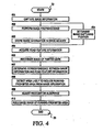
- Fig. 4 is a flowchart indicating a specific example of an image recognition process performed by an image recognition apparatus according to an embodiment of the present invention.
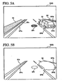
- Fig. 5A shows an example of image information captured by an image pickup apparatus
- Fig. 5B shows an example of image information obtained by performing preprocessing on the image information shown in Fig. 5A .
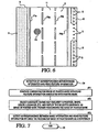
- Fig. 6 is a diagram showing an example of road feature information acquired by a road feature information calculation unit of an image recognition apparatus according to an embodiment of the present invention.
- Fig. 7 is a flowchart associated with a process (step #07) performed by an image recognition apparatus to determine correspondence between image information and road feature information, according to an embodiment of the present invention.
- Fig. 8A is a diagram showing only images of painted marks extracted, in step #72, from image information
- Fig. 8B is a diagram showing a state in which the total image shown in Fig. 8A is divided into areas based on boundary lines.
- Fig. 9 is a graph showing the number of edge points detected across the width of a road from the image information shown in Fig. 5 .
- Fig. 10 is a diagram representing images recognized from image information G in steps #7 and #10 by an image recognition apparatus according to an embodiment of the present invention.
- FIG. 1 is a schematic block diagram illustrating a hardware configuration of the image recognition apparatus 1 according to the present embodiment.
- the image recognition apparatus 1 mainly includes an image information acquisition unit 3 adapted to capture image information G from an image pickup apparatus 2 installed in a vehicle M ( Fig. 2 ), a GPS (Global Positioning System) receiver 4, a position calculation unit 7 adapted to determine the position of an image captured by the image pickup apparatus 2 based on an output from a direction sensor 5 and an output from a distance sensor 6, a road feature information calculation unit 9 adapted to perform a calculation to acquire, from map information stored in a map information database 8, road feature information C associated with a feature in the neighborhood of the position of the image captured by the image pickup apparatus 2, and an image information recognition unit 10 adapted to recognize image information G by using the acquired road feature information C and recognize an image of a recognition target corresponding to the feature included in the image information.
- an image information acquisition unit 3 adapted to capture image information G from an image pickup apparatus 2 installed in a vehicle M ( Fig. 2 )
- GPS Global Positioning System
- position calculation unit 7 adapted to determine the position of an image captured by the image pickup apparatus 2 based
- the position calculation unit 7, the GPS receiver 4, the direction sensor 5, the distance sensor 6, and the map information database 8, are usually included in an in-vehicle navigation apparatus designed to provide route guidance information.
- the "position information acquisition means" according to the present embodiment of the invention is realized by the position calculation unit 7, the GPS receiver 4, the direction sensor 5, and the distance sensor 6.
- the image pickup apparatus 2 includes, for example, an image sensor such as a CCD sensor or a CMOS sensor, and a lens serving as an optical system for guiding light to the image sensor.
- the image pickup apparatus 2 is disposed, in a position aimed in a forward or backward direction, at a location denoted by Q1 to Q3 in Fig. 2 in the vehicle M such that the image pickup apparatus 2 can take an image of the road surface of a road 11 on which the vehicle M runs and can take an image of nearby objects.
- a conventional in-vehicle camera designed to take an image of a scene viewed forward or backward from the vehicle M may be used as the image pickup apparatus 2.
- the image information acquisition unit 3 includes an interface circuit 12 for interfacing with the image pickup apparatus 2, an image preprocessing circuit 13 adapted to perform preprocessing on the image information G supplied from the image pickup apparatus 2, and an image memory 14 for storing the preprocessed image information G.
- the interface circuit 12 includes an analog-to-digital converter that captures analog image information G taken by the image pickup apparatus 2 at predetermined time intervals, converts it into a digital signal, and outputs the resultant digital signal to the image preprocessing circuit 13.
- the time interval at which the interface circuit 12 captures the image information G is set, for example, within the range of 10 to 50 msec so that the image information acquisition unit 3 can substantially continuously acquire the image information of the road 11 along which the vehicle M runs.
- the image preprocessing circuit 13 performs preprocessing, such as binarization and edge detection, on the image information G to make it easy for the image information recognition unit 10 to perform image recognition.
- the resultant preprocessed image information G is stored in the image memory 14.
- the interface circuit 12 In addition to the image information G supplied to the image preprocessing circuit 13, the interface circuit 12 also supplies the image information G directly to the image memory 14. Thus, both the image information G2 subjected to the preprocessing performed by the image preprocessing circuit 13 and the original image information G1 that is not subjected to the preprocessing are stored in the image memory 14.
- the image information acquisition unit 3 serves as the "image information acquisition means” according to the invention.
- the position calculation unit 7 is connected to the GPS receiver 4, the direction sensor 5 and the distance sensor 6.
- the GPS receiver 4 is a device that receives a signal from a GPS satellite to acquire information in terms of, for example, the position (the latitude and the longitude) and the moving speed of the GPS receiver 4.
- the direction sensor 5 includes a geomagnetic sensor or a gyroscopic sensor, an optical rotation sensor or a rotation-type potentiometer disposed on a rotating part of a steering wheel, or an angle sensor disposed on a wheel, for detecting the direction in which the vehicle M runs.
- the distance sensor 6 for detecting the moving distance of the vehicle M includes a vehicle speed sensor for detecting the number of revolutions of a wheel, or a combination of a yaw/acceleration sensor for detecting the acceleration of the vehicle M and a circuit adapted to integrate the detected acceleration twice.
- the position calculation unit 7 calculates the current position of the vehicle M based on the signals output from the GPS receiver 4, the direction sensor 5, and the distance sensor 6. The calculated position of the vehicle M is also employed as the position of the image pickup apparatus 2.
- the position calculation unit 7 is also connected to the interface circuit 12 of the image information acquisition unit 3.
- the interface circuit 12 outputs a signal to the position calculation unit 7 when an image taking operation is performed by the image pickup apparatus 2. This allows the position calculation unit 7 to determine the position at which the image information G was captured, by determining the position of the image pickup apparatus 2 as of when the signal was received from the interface circuit 12.
- the capturing position of the image information G determined by the position calculation unit 7 is expressed in latitude and longitude and is output to the road feature information calculation unit 9.
- the position calculation unit 7 includes a processing unit such as a CPU serving as a core device and also includes functional parts implemented by hardware or software or by a combination of hardware and software for performing various processes on input data.
- a processing unit such as a CPU serving as a core device and also includes functional parts implemented by hardware or software or by a combination of hardware and software for performing various processes on input data.
- the road feature information calculation unit 9 is connected to the position calculation unit 7 and the map information database 8.
- Fig. 3 is a schematic diagram illustrating contents of map information stored in the map information database 8.
- a road network layer L1 As shown in Fig. 3 , in the map information database 8 according to the present embodiment, a road network layer L1, a road shape layer L2, and a feature layer L3 are stored as map information.
- information indicating connections among roads 11 is represented. More specifically, information associated with a large number of nodes N with position information on the map represented in latitude and longitude and information associated with a large number of links L corresponding to roads 11 that connect two adjacent nodes N are represented in the road network layer L1.
- the information associated with each link L includes information indicating the type of each road 11 (expressway, toll road, national road, or prefectural road) and the length of the link.
- the road shape layer L2 represents shapes of roads 11 and is stored in connection with the road network layer L1. More specifically, road shape layer L2 includes information indicating positions expressed in latitude and longitude on the map for a large number of supplementary road shape points S located between two adjacent nodes N (on links L) and also includes information indicating the road width W at each supplementary road shape point S.
- the feature layer L3 includes information associated with features located on or in the neighborhood of the road 11 and is stored in connection with the road network layer L1 and the road shape layer L2.
- the feature information described in the feature layer L3 includes at least information in terms of the position, the shape, the color, etc. of features that can be objects to be recognized by the image recognition apparatus 1. More specifically, in the present embodiment, the feature information includes information in terms of the position on the map with respect to the supplementary road shape point S or the node N, the shape, the color, etc. for various features such as painted marks P on the surface of the road 11, running-prohibited areas I adjacent to the road 11, and various kinds of traffic signs 15 and traffic signals 16 on the road 11.
- the painted marks P include, for example, boundary lines (and information indicating the types of boundary lines, such as a solid line, a broken line, a double line) between adjacent traffic lanes, zebra zone marks, an allowed driving direction mark indicating the allowed driving direction for each lane, stop lines, pedestrian crossing marks, and speed limit signs.
- the painted marks P also include manholes formed on surfaces of the road 11, although manholes are not painted marks in a strict sense.
- the running-prohibited area I includes, for example, road shoulders adjacent to the road, and sidewalks.
- the map information database 8 is realized on a hardware device including a storage medium adapted to store information and a device adapted to drive the storage medium, such as a hard disk drive, a DVD drive with a DVD-ROM, or a CD drive with a CD-ROM
- the road feature information calculation unit 9 Based on information indicating the capturing position in latitude and longitude of the image information G determined by the position calculation unit 7, the road feature information calculation unit 9 performs a calculation to acquire road feature information C associated with features in the neighborhood of the capturing position of the image information G from the map information C stored in the map information database 8. More specifically, the road feature information calculation unit 9 extracts feature information as road feature information C in terms of the position, the shape, the color, etc. of features included in an area in the neighboring of the capturing position of the image information G, including at least the area whose image is taken by the image pickup apparatus 2, from the feature layer L3 of the map information database 8.
- the road feature information calculation unit 9 includes a processing unit such as a CPU serving as a core device and also includes functional parts implemented by hardware or software or by a combination of hardware and software for performing various processes on input data.
- the road feature information calculation unit 9 serves as the “road feature information acquisition means” according to the invention.
- the image information recognition unit 10 is connected to the image memory 14 of the image information acquisition unit 3 and also to the road feature information calculation unit 9.
- the image information recognition unit 10 recognizes the image information G using the road feature information C acquired by the road feature information calculation unit 9 to recognize images of objects to be recognized included in the image information G.
- the objects to be recognized by the image information recognition unit 10 corresponds to features described as feature information in the feature layer L3, such as the painted marks P, the running-prohibited areas 1, various traffic signs 15, and traffic signals 16.
- the image information recognition unit 10 includes a processing unit such as a CPU serving as a core device and also includes functional parts implemented by hardware or software or by a combination of hardware and software for performing various processes on input data.
- a processing unit such as a CPU serving as a core device and also includes functional parts implemented by hardware or software or by a combination of hardware and software for performing various processes on input data.
- the image information recognition unit 10 serves as the image information recognition means according to the present invention.
- the recognition process of the image information G performed by the image information recognition unit 10 using the road feature information C may be accomplished by one of or a combination of the following two methods.
- a first image recognition method includes extracting candidates for an image of a recognition target to be recognized from the image information G, comparing the extracted candidate image with the road feature information C, and selecting a candidate image with high similarity with the road feature information C as the image of the recognition target, thereby recognizing the image of the object.
- a second image recognition method includes extracting, based on the road feature information C, an area likely to include an image of a recognition target to be recognized, from the image information G, adjusting, based on the extraction result, the recognition algorithm such that the judgment criterion for the area likely to include the image of the recognition target becomes lower than the judgment criterion for the other areas, and extracting a correct image of the recognition target from the image information G, thereby recognizing the image of the recognition target.
- the image information recognition unit 10 recognizes painted marks P on the surface of the road 11 and running-prohibited areas I adjacent to the road 11, by using a combination of the first and second image recognition methods.
- the image information recognition unit 10 includes a painted mark recognition unit 10a, a road feature information comparison unit 10b, a likely area extraction unit 10c, and a running-prohibited area recognition unit 10d.
- painted marks P can be easily recognized because of their great difference in brightness or color from the surface of the road 11, and the painted marks P correspond to "first objects to be recognized" according to the present invention.
- running-prohibited areas I such as a road shoulder, a sidewalk, or a traffic strip do not have a great difference in brightness or color from the road 11 or other neighboring features, and thus it is generally difficult to detect edges thereof, even if edge enhancement or the like is performed.
- running-prohibited areas I correspond to "second objects to be recognized” according to the present invention.
- the image recognition apparatus 1 captures image information G taken by the image pickup apparatus 2 (step #01). More specifically, the image recognition apparatus 1 transmits the image information G taken the image pickup apparatus 2 such as an in-vehicle camera to the image preprocessing circuit 13 and the image memory 14 via the interface circuit 12. At a time at which the image information G is supplied from the image pickup apparatus 2, which is substantially the same as the time at which an image is taken by the image pickup apparatus 2, the interface circuit 12 outputs a timing signal to the position calculation unit 7 to inform the position calculation unit 7 of the timing of taking the image.
- the image preprocessing circuit 13 Upon receiving the image information G, the image preprocessing circuit 13 performs the preprocessing on the received image information G (step #02).
- the preprocessing performed here is, for example, binarization or edge detection to make it easy for the image information recognition unit 10 to perform image recognition.
- Fig. 5A shows an example of image information G (G1) taken by the image pickup apparatus 2
- Fig. 5B shows an example of image information G (G2) obtained by preprocessing the image information G shown in Fig. 5A .
- an image indicating an outline of a thing imaged as image information G by an edge search process is extracted.
- the image information G2 obtained via the preprocessing in step #02 and the image information G1 directly received from the interface circuit 12 are stored in the image memory 14 (step #03).
- the position calculation unit 7 determines the capturing position of the image information G (step #04). More specifically, when the signal indicating the timing of outputting the image information G is received from the interface circuit 12, the position calculation unit 7 regards the received signal as indicating the time at which the image was taken by the image pickup apparatus 2, and the position calculation unit 7 determines the current position of the vehicle M, based on information supplied from the GPS receiver 4, the direction sensor 5, and the distance sensor 6. The current position of the vehicle M determined in this way is employed as the capturing position of the image information G. The determined capturing position is expressed in latitude and longitude, and supplied to the road feature information calculation unit 9.
- the road feature information calculation unit 9 acquires road feature information C associated with features in the neighborhood of the capturing position of the image information G, from the map information stored in the map information database 8. (step #05). In this process, the road feature information calculation unit 9 extracts, from wide-area map information stored in the map information database 8, road feature information C associated with features located within a particular range R from the capturing position determined in step #04. It is desirable that the range R from the capturing position be set such that the area whose image is taken as the image information G by the image pickup apparatus 2 is included within the range R.
- Fig. 6 illustrates, in the form of a drawing, an example of road feature information C acquired by the road feature information calculation unit 9.
- features included in the road feature information C are painted marks P including two boundary lines P1a and P1b in the form of solid lines indicating outer side edges of a road 11 having three traffic lanes for each driving direction, two dashed boundary lines P2a and P2b between adjacent lanes of the three traffic lanes, and a manhole P3 in the leftmost lane of the three traffic lanes.
- Running-prohibited areas I include a sidewalk 11 adjacent on the left to the road 11 and a central traffic strip 12 adjacent on the right to the road 11. Note that the road feature information C shown in Fig. 6 is by way of example only, and the road feature information C may include various features depending on the capturing position of the image information G.
- the road feature information C includes position information, shape information, and color information associated with respective features.
- the position information of each feature indicates the position with respect to a supplementary road shape point S (or a node N such as an intersection ( Fig. 3 )). More specifically, the position information is given only by the distance (offset) from a supplementary road shape point S (or a node N) for features located along the road 11, such as boundary lines P1a and P1b in the form of solid lines, boundary lines P2a and P2b in the form of broken lines, and running-prohibited areas I such as a sidewalk 11 and a central traffic strip 12.
- the position information is represented by the distance and the direction with respect to a specific supplementary road shape point S (or a node N).
- the shape information of each feature includes information representing the size (the width, the depth, and the height) with respect to the position indicated by the position information and also information representing the shape (contour). It is desirable that the shape information be represented in a simplified form that allows it to easily make a comparison with the image information G.
- the painted mark recognition unit 10a of the image information recognition unit 10 recognizes images of painted marks P included in the image information G (step #06). That is, in the present embodiment, candidates for images of painted marks P are extracted from the image information G2 obtained as a result of the preprocessing in step #02. More specifically, as shown in Fig. 5B , images having high similarity with feature data such as templates representing features of painted marks P such as boundary lines and manholes are extracted from the image information G2 obtained via the preprocessing such as the edge enhancement, and extracted images are employed as candidates for images of the painted marks P. In the example shown in Fig.
- an image GS of a vehicle running ahead and an image GP2b of a boundary line in the form of a broken line on the right-hand side, partially hidden by the vehicle, are discarded, and the other images, that is, an image GP2a of a boundary line in the form of a broken line on the left-hand side, an image GP1a of a boundary line in the form of a solid line on the left-hand side, an image Gl1a of a curb of a sidewalk on the outer side thereof, an image GPlb of a boundary line in the form of a solid line on the right-hand side, and an image GP 3 of a manhole are employed as candidates for the images of painted marks P.
- the painted marks P corresponds to "first recognition targets” according to the present invention
- the painted mark recognition unit 10a that recognizes images of painted marks P servers as the "first target recognition means” according to the present invention.
- the road feature information comparison unit 10b of the image information recognition unit 10 compares the recognition result of the image of the pained mark P in step #06 with the road feature information C in terms of the painted mark P acquired in step #05 to detect the correspondence between the image information G and the road feature information C (step #07). More specifically, in the present embodiment, candidates for the image of the painted mark P are compared with the road feature information C associated with the painted mark P, and a candidate having high similarity with the road feature information C is employed as the image of the painted mark P thereby recognizing the image of the painted mark P. Thereafter, the correspondence between the image information G and the road feature information C is detected by using the recognized image of the painted mark P as a reference.
- the road feature information comparison unit 10b serve as the "road feature information comparison means" according to the present invention.
- Fig. 7 is a flowchart showing a process in step #07 according to the present embodiment.
- candidates for the image of the painted mark P extracted in step #06 are compared with information that is acquired in step #05 from the road feature information C and that is associated with the painted mark P (step #71), to extract a candidate having high similarity with the information in terms of the position, the shape, the color, and/or the brightness. (step #72).
- step #72 In the example shown in Fig.
- the image GIla of the curb of the sidewalk to the left of the solid boundary line GP1a on the left-hand side is discarded in the process of step #72.
- the candidates for the images extracted in this way are regarded as the images of the painted marks P. Note that the information in terms of the color, the luminance, and the like of the candidate images of the painted marks P can be acquired from the original image information G that is not subject to the preprocessing and that is stored in the image memory 14.
- Fig. 8A is a diagram showing only images of the painted marks P extracted from the image information G in the process of step #72. Note that the image GP2b of the broken boundary line on the right-hand side has been discarded together with the image GS of the vehicle from the candidate images of the painted marks P, and thus they are not included in the extracted images of the painted marks P (they are represented by dotted lines in Fig. 8A ).
- the correspondence between the image information G and the road feature information C is detected by using the recognized image of the painted mark P as a reference (step #73). More specifically, the correspondence between the respective features included in the road feature information C and the images included in the image information G is determined based on the correspondence between the positions of the images of the painted marks P recognized in the image information G and the positions of the painted marks P included in the road feature information C. In this determination process, by employing a feature extending along the road 11, such as the boundary lines GP1a or GP2a, as a reference, it is possible to precisely determine the positional correspondence in the direction across the width of the road 11.
- a feature extending along the road 11 such as the boundary lines GP1a or GP2a
- the likely area extraction unit 10c of the image information recognition unit 10 detects an area likely to include an image of a running-prohibited area I from the image information G, based on the correspondence, determined in step #07, between the road feature information C and the image information G (step #08). That is, based on the correspondence determined in step #07 between the road feature information C and the image information G, it is possible to detect very likely locations of images of respective features including the painted marks P and the running-prohibited areas I in the image information G. Thus, the area in the image information G with the position and the color corresponding to the position and the color of the running-prohibited area I in the road feature information C is detected based on the correspondence determined in step #07.
- the resultant area detected in step #08 is regarded as the area of the image of the running-prohibited area 1.
- the total image area of the image information G acquired via the shooting is roughly divided into areas A1 to A3 respectively including the boundary lines P1a, P1b and P2a and areas A4 to A7 respectively located between two adjacent areas of A1 to A3.
- a judgment is made as to whether each of the areas A4 to A7 includes the running-prohibited area 1, thereby detecting an area very likely to include the image of the running-prohibited area 1.
- Fig. 8B based on the boundary lines P1a, P1b and P2a included in the painted marks P extracted in step #72.
- step #09 the recognition algorithm of the recognition process performed by the running-prohibited area recognition unit 10d of the image information recognition unit 10 is adjusted based on the detection result in step #08 (step #09), and the images of the running-prohibited areas I included in the image information G are recognized (step #10).
- the recognition algorithm is adjusted such that the criterion to determine whether an area includes a running-prohibited area I becomes lower for the areas A4 and A7 determined in step #08 to very likely include the running-prohibited area I than for the other areas (the areas A5 and A6 in this specific case).
- running-prohibited areas I such as a sidewalk I1, a traffic strip I2, and a road shoulder are similar in luminance or color to the road 11 or other neighboring objects, and thus it is generally difficult to detect an edge thereof even if edge enhancement is performed. Therefore, in general, it is more difficult to recognize such a running-prohibited area I than painted marks P.
- the above difficulty can be solved by adjusting the recognition algorithm such that the criterion to determine whether an area includes a running-prohibited area I becomes lower for the areas A4 and A7 determined in step #08 to very likely include the running-prohibited area I than for the other areas, thereby achieving high recognition accuracy for the running-prohibited areas 1.
- Adjusting of the recognition algorithm such that the criterion to determine whether an area includes a running-prohibited area I becomes lower for a particular area can be accomplished in many ways.
- One method is, as described above, to lower the criterion for an area, such as A4 or A7 in the above-described example, detected as being very likely to include an image of a running-prohibited area 1.
- Another method is to increase the criterion for areas other than the areas A4 and A7.
- Still another method is to lower the criterion for the areas A4 and A7 and increase the criterion of the other areas.
- a proper method of adjusting the recognition algorithm may be selected depending on the method of recognizing the running-prohibited areas 1.
- the algorithm of recognizing the image of the running-prohibited area I involves detecting edges of images included in the image information G, detecting the number of edge points at respective locations across the width of the road 11, and determining that a running-prohibited area I exists in an area where a greater number of edge points than a predetermined threshold value are detected.
- two different threshold values may be used. A first threshold value t1 is set to be low, and a second threshold value t2 is set to be high, as shown in Fig. 9 .
- the first threshold value t1 is used for areas, such as the areas A4 and A7 in this specific example, determined as areas highly likely to include an image of a running-prohibited area 1
- the second threshold value t2 is used for the other areas, such as the areas A5 and A6, thereby adjusting the recognition algorithm such that the criterion to determine whether an area of interest is a running-prohibited area I becomes lower for areas, such as the areas A4 and A7 in the present example, determined as areas highly likely to include an image of a running-prohibited area I than for other areas, such as the areas A5 and A6.
- Fig. 9 is a graph showing the number of edge points detected across the width of the road 11 from the image information G shown in Fig. 5 .
- the areas A1 to A3 have a large number of edge points, because these areas respectively include the boundary lines P1a, P1b, and P2b.
- these areas A1 to A3 are not included in areas to be examined to detect a running-prohibited area 1.
- the area A5 of an asphalt road generally has a small number of edge points except for an area corresponding to the manhole P3.
- the areas A4, A6, and A7 have a rather large number of edge points.
- the edge points in the areas A4 and A7 correspond to edges of the running-prohibited areas I such as the sidewalk I1 or the central traffic strip I2, while the edge points in the area A6 correspond to edges of the image Gs of a vehicle running ahead or edges of the broken boundary line GP2b partially hidden behind the image Gs of the vehicle.
- the first threshold value t1 set to be low is applied as the criterion for the detection of running-prohibited areas I to the areas A4 and A7 determined to be highly likely to include an image of a running-prohibited area 1, while the second threshold value t2 set to be high is applied as the criterion for the detection of running-prohibited areas I to the other areas such as areas A5 and A6.
- the adjustment of the threshold value in accordance with the detection of the highly likely areas in step #08 makes it possible to reduce the probability of missing a running-prohibited area I existing in an area such as areas A4 and A7 determined to be highly likely to include an image of the running-prohibited area 1, while it is possible to reduce the probability of detecting a wrong area such as A5 or A6 as a running-prohibited area 1.
- the specific values of the first threshold value t1 and the second threshold value t2 may be properly determined experimentally or statistically. It is also preferable that the first threshold value t1 and the second threshold value t2 be set variably depending on information extracted from the image information G or depending on a signal output from a sensor installed in the vehicle M.
- a running-prohibited area I such as a road shoulder, a sidewalk, or a traffic strip.
- a running-prohibited area I such as a road shoulder, a sidewalk, or a traffic strip.
- an image GI1 of the sidewalk I1 located to the left of the image GP1a of the boundary line P1a and an image G12 of the central traffic strip 12 located to the right of the image GP1b of the boundary line P1b are recognized.
- step #01 to #10 described above is performed repeatedly at predetermined time intervals to achieve real-time image recognition while the vehicle M is running.
- the image recognition apparatus 1 described above may be applied to a vehicle control apparatus for controlling the running of the vehicle M or to a navigation apparatus for displaying the vehicle position.
- a vehicle control apparatus for controlling the running of the vehicle M or to a navigation apparatus for displaying the vehicle position.
- use of the image recognition apparatus 1 in a vehicle control apparatus makes it possible to recognize a status or a condition of an environment where the vehicle M is running, based on an image recognized by the image information recognition unit 10 such as the distance and/or the direction of a running-prohibited area I such as a sidewalk or a traffic strip with respect to the vehicle M, or the distance and/or the direction of a stop line, a boundary line, a pedestrian crossing, or the like with respect to the vehicle M.
- This makes it possible to control the running of the vehicle in terms of the steering and/or the acceleration/deceleration so that the vehicle runs along a correct lane and so that the vehicle M is prevented from encountering a traffic accident.
- the image recognition apparatus 1 in a navigation apparatus makes it possible to detect the vehicle position more precisely based on the result of image recognition performed by the image information recognition unit 10, than is possible by using only the conventional GPS receiver 4, the direction sensor 5, and the distance sensor 6. This makes it possible to display the vehicle position in a more detailed manner in which, for example, information indicating a lane the vehicle is running is provided, and it also becomes possible to provide route guidance at a most opportune time based on the information indicating the detailed vehicle position.
- painted marks P on the surface of the road 11 and running-prohibited areas I adjacent to the road 11 are recognized using a combination of the first image recognition method and the second image recognition method.
- the first image recognition method may be used to extract candidates for images of painted marks P or running-prohibited areas I, compare the extracted candidates with road feature information C, and employ candidates having high similarity with the road feature information C as images of painted marks P or running-prohibited areas 1.
- the second image recognition method may be used to recognize images of painted marks P and/or running-prohibited areas 1. That is, based on the image capturing position determined by the position , calculation unit 7 and based on the road feature information C, areas likely to include an image of a painted mark P or a running-prohibited area I are extracted from the image information G. Based on the extracted likely areas, the recognition algorithm is adjusted such that the criterion to determine whether an area of interest is a painted mark P or a running-prohibited area I becomes lower for the areas determined highly likely to include an image of a painted mark P or a running-prohibited area 1, and an image of an area which should be recognized is correctly recognized from the image information G.
- the image recognition apparatus 1 is installed in the vehicle M.
- the application of the image recognition apparatus 1 is not limited to installation in the vehicle M, but the image recognition apparatus 1 may be applied to a wide variety of apparatuses or systems in which the image pickup apparatus 2 moves on a road.
- the image recognition apparatus 1 may also used to recognize a still image taken on a road.
- the image recognition apparatus 1 it is not necessarily needed to dispose all parts of the image recognition apparatus 1 in a vehicle M.
- one or more parts other than the image pickup apparatus 2 may be disposed in the outside of the vehicle M and the one or more parts may be connected to parts disposed in the vehicle M via a network such as the Internet so that information or a signal is transmitted between them via the network thereby realizing the image recognition apparatus 1.
- the functions of the image information recognition unit 10 may be executed by an external server or the like.
- the image recognition apparatus and the image recognition method according to the present invention can be advantageously used in various applications to recognize image information taken by an image pickup apparatus moving along a road as with an image pickup apparatus installed in a vehicle.
Landscapes
- Engineering & Computer Science (AREA)
- Physics & Mathematics (AREA)
- Geometry (AREA)
- Software Systems (AREA)
- General Physics & Mathematics (AREA)
- Theoretical Computer Science (AREA)
- Multimedia (AREA)
- Remote Sensing (AREA)
- Computer Graphics (AREA)
- Automation & Control Theory (AREA)
- Mechanical Engineering (AREA)
- Transportation (AREA)
- Traffic Control Systems (AREA)
- Navigation (AREA)
- Image Processing (AREA)
- Image Analysis (AREA)
Claims (10)
- Bilderkennungsvorrichtung, die aufweist:eine Karteninformationsdatenbank (8), in der Karteninformationen beschrieben werden;ein Positionsinformations-Erfassungsmittel (4, 5, 6, 7) zum Erfassen von Fahrzeugpositionsinformationen;ein Bildinformations-Erfassungsmittel (3) zum Erfassen von Bildinformationen (G) eines Bilds, das auf einer Straße (11) aufgenommen wird;ein Straßenmerkmalsinformations-Erfassungsmittel (9) zum Erfassen aus den Karteninformationen in der Kartendatenbank von Straßenmerkmalsinformationen (C), die mit einem Straßenmerkmal in der Nachbarschaft der Fahrzeugposition verknüpft sind, die durch das Positionsinformations-Erfassungsmittel (4, 5, 6, 7) erfasst wird; undein Bildinformations-Erkennungsmittel (10) zum Erkennen der Bildinformationen (G) mittels der Straßenmerkmalsinformationen (C), um ein Bild eines Erkennungsziels zu erkennen, das dem Merkmal entspricht, das in den Bildinformationen (G) enthalten ist;wobei das Bildinformations-Erkennungsmittel (10) eine Straßenmerkmalsinformations-Vergleichseinheit (10b) aufweist, die konfiguriert ist:einen oder mehrere Kandidaten für das Bild eines ersten Erkennungsziels (P) aus den Bildinformationen (G) zu extrahieren,die extrahierten Kandidaten mit den Straßenmerkmalsinformationen (C) zu vergleichen, einen Kandidaten, der eine große Ähnlichkeit mit den Straßenmerkmalsinformationen (C) aufweist, als das Bild des ersten Erkennungsziels (P) einzusetzen, wodurch das Bild des ersten Erkennungsziels (P) erkannt wird, undPositionsentsprechungen zwischen den Bildinformationen (G) und weiteren Straßenmerkmalsinformationen wie Fahrverbotsbereiche (I) unter Verwendung der Positionen des erkannten Bilds des ersten Erkennungsziels (P) als Referenz festzustellen;wobei das Bildinformations-Erkennungsmittel (10) ferner eine Einheit (10c) zur Extraktion wahrscheinlicher Bereiche aufweist, die konfiguriert ist:Bereiche, bei denen es wahrscheinlich ist, dass sie ein Bild eines Fahrverbotsbereichs (I) enthalten, beruhend auf den Positionsentsprechungen zu ermitteln, die durch die Straßenmerkmalsinformations-Vergleichseinheit (10b) festgestellt werden;beruhend auf dem Ermittlungsresultat der Einheit (10c) zur Extraktion wahrscheinlicher Bereiche einen Erkennungsalgorithmus einer Fahrverbotsbereich-Erkennungseinheit (10d) unter Verwendung eines ersten und eines zweiten Schwellenwerts t1 und t2 als ein vorgegebenes Kriterium einzustellen, um festzustellen, ob ein interessierendes Bild ein Bild des Fahrverbotsbereichs (I) ist, so dass der erste Schwellenwert t1, der für die Bereiche verwendet wird, bei denen es wahrscheinlich ist, dass sie das Bild des Fahrverbotsbereichs (I) enthalten, niedrig eingestellt wird, und der zweite Schwellenwert t2, der für die restlichen Bereiche verwendet wird, hoch eingestellt wird, wobei t1 < t2; undwobei die Fahrverbotsbereich-Erkennungseinheit (10d) konfiguriert ist:Kanten von Bildern zu ermitteln, die in den Bildinformationen (G) enthalten sind, die Anzahl von Kantenpunkten an jeweiligen Stellen über die Breite der Straße (11) zu ermitteln, undfestzustellen, dass ein Fahrverbotsbereich (I) in einem Bereich vorhanden ist, wo eine Anzahl von Kantenpunkten ermittelt wird, die größer als das vorgegebene Kriterium ist, das auf dem ersten und zweiten Schwellenwert t1, t2 beruht.
- Bilderkennungsvorrichtung nach Anspruch 1, wobei die Straßenmerkmalsinformationen (C) ferner Forminformationen und/oder Farbinformationen umfassen, die mit dem Straßenmerkmal verknüpft sind.
- Bilderkennungsvorrichtung nach Anspruch 1 oder 2, wobei das Straßenmerkmal ferner eines oder beides einer aufgemalten Markierung (P) auf der Oberfläche einer Straße umfasst.
- Bilderkennungsvorrichtung nach einem der Ansprüche 1 bis 3, wobei :die Straßenmerkmalsinformations-Erfassungseinheit (3) konfiguriert ist, aus Karteninformationen Straßenmerkmalsinformationen (C) zu erfassen, die mit einem ersten Merkmal und einem zweiten Merkmal in der Nachbarschaft der Fahrzeugposition verknüpft sind;die erste Zielerkennungseinheit (10a) konfiguriert ist, ein Bild des ersten Erkennungsziels (P) zu erkennen, das dem ersten Merkmal entspricht, das in den Bildinformationen (G) enthalten ist;die Straßenmerkmalsinformations-Vergleichseinheit (10b) konfiguriert ist, das Bild des ersten Erkennungsziels (P) mit den Straßenmerkmalsinformationen (C) zu vergleichen,die mit dem ersten Merkmal verknüpft sind, um die Positionsentsprechung zwischen den Bildinformationen (G) und den weiteren Straßenmerkmalsinformationen zu ermitteln; unddie Einheit (10c) zur Extraktion wahrscheinlicher Bereiche konfiguriert ist, Bereiche, bei denen es wahrscheinlich ist, dass sie ein Bild eines zweiten Erkennungsziels enthalten, die dem zweiten Merkmal entsprechen, als Fahrverbotsbereiche (I) zu ermitteln, beruhend auf den Positionsentsprechungen, die durch die Straßenmerkmalsinformations-Vergleichseinheit (10b) festgestellt werden.
- Bilderkennungsvorrichtung nach Anspruch 4, wobei
die erste Zielerkennungseinheit (10a) konfiguriert ist, einen oder mehrere Kandidaten für das Bild des ersten Erkennungsziels (P) aus den Bildinformationen (G) zu extrahieren; und
die Straßenmerkmalsinformations-Vergleichseinheit (10b) konfiguriert ist den einen oder die mehreren Kandidaten für das Bild des ersten Erkennungsziels (P) mit den Straßenmerkmalsinformationen (C) zu vergleichen, die mit dem ersten Merkmal verknüpft sind, das durch die Straßenmerkmalsinformations-Erfassungseinheit (3) erfasst wird,
einen Kandidaten einzusetzen, der eine große Ähnlichkeit zu dem Bild des ersten Erkennungsziels aufweist, wodurch das Bild des ersten Erkennungsziels erkannt wird, und eine Entsprechung zwischen den Bildinformationen und den Straßenmerkmalsinformationen unter Verwendung des erkannten Bilds des ersten Erkennungsziels als Referenz zu ermitteln. - Bilderkennungsvorrichtung nach einem der Ansprüche 1 bis 5, wobei das Straßenmerkmalsinformations-Erfassungsmittel (9) aus Karteninformationen, die in der Informationsdatenbank (8) beschrieben werden, die in einer Navigationsvorrichtung (4, 5, 6, 7, 8) vorgesehen ist, die Straßenmerkmalsinformationen (C) in der Nachbarschaft einer Fahrzeugposition erfasst, die, wenn Bildinformationen (G) durch die Bildaufnahmevorrichtung (2) erfasst werden, durch die Positionsinformations-Erfassungseinheit (3) erfasst wird, die in der Navigationsvorrichtung (4, 5, 6, 7, 8) vorgesehen ist.
- Navigationsvorrichtung, die aufweist:eine Bilderkennungsvorrichtung nach einem der Ansprüche 1 bis 6.
- Navigationsvorrichtung nach Anspruch 7, die ferner Positionsinformations-Erfassungsmittel zum Erfassen von Fahrzeugpositionsinformationen und Fahrzeugpositions-Korrekturmittel zum Korrigieren der Fahrzeugpositionsinformationen beruhend auf einem Resultat der Erkennung aufweist, die durch das Bildinformations-Erkennungsmittel (10) durchgeführt wird.
- Bilderkennungsverfahren, das die Schritte aufweist:Erfassen von Fahrzeugpositionsinformationen;Erfassen von Bildinformationen eines Bilds, das auf einer Straße (11) aufgenommen wird;Erfassen von Karteninformationen in einer Kartendatenbank (8) von Straßenmerkmalsinformationen (C), die mit einem Straßenmerkmal in der Nachbarschaft der Fahrzeugposition verknüpft sind, die durch das Positionsinformations-Erfassungsmittel (4, 5, 6, 7) erfasst wird; undErkennen der Bildinformationen (G) mittels der Straßenmerkmalsinformationen (C), um ein Bild eines ersten Erkennungsziels (P) zu erkennen, das einem Merkmal entspricht,das in den Bildinformationen (G) enthalten ist, durch:- Vergleichen von Straßenmerkmalsinformationen, das die Schritte aufweist:Extrahieren von einem oder mehreren Kandidaten für das Bild eines ersten Erkennungsziels (P) aus den Bildinformationen (G),Vergleichen der extrahierten Kandidaten mit den Straßenmerkmalsinformationen (C), Einsetzen eines Kandidaten, der eine große Ähnlichkeit mit den Straßenmerkmalsinformationen (C) aufweist, als das Bild des ersten Erkennungsziels (P), wodurch das Bild des ersten Erkennungsziels (P) erkannt wird, undFeststellen einer Positionsentsprechung zwischen den Bildinformationen (G) und weiteren Straßenmerkmalsinformationen wie einem Fahrverbotsbereich (I) unter Verwendung der Position des erkannten Bilds des ersten Erkennungsziels (P) als Referenz;- Ermitteln von Bereichen, bei denen es wahrscheinlich ist, dass sie ein Bild eines Fahrverbotsbereichs (I) enthalten, beruhend auf Positionsentsprechungen zwischen den Bildinformationen (G) und weiteren Straßenmerkmalsinformationen wie Fahrverbotsbereiche (I) unter Verwendung der Positionen des erkannten Bilds des ersten Erkennungsziels (P) als Referenz;- Einstellen beruhend auf dem Resultat der Ermittlung wahrscheinlicher Bereiche eines Erkennungsalgorithmus zum Erkennen eines Fahrverbotsbereichs unter Verwendung eines ersten und eines zweiten Schwellenwerts t1 und t2 als ein vorgegebenes Kriterium, um festzustellen, ob ein interessierendes Bild ein Bild des Fahrverbotsbereichs (I) ist, so dass der erste Schwellenwert t1, der für die Bereiche verwendet wird, bei denen es wahrscheinlich ist, dass sie das Bild des Fahrverbotsbereichs (I) enthalten, niedrig eingestellt wird, und der zweite Schwellenwert t2, der für die restlichen Bereiche verwendet wird, hoch eingestellt wird, wobei t1 < t2; und wobei das Erkennen eines Fahrverbotsbereichs die Schritte aufweist:Ermitteln von Kanten von Bildern, die in den Bildinformationen (G) enthalten sind,Ermitteln der Anzahl von Kantenpunkten an jeweiligen Stellen über die Breite der Straße (11), undFeststellen, dass ein Fahrverbotsbereich (I) in einem Bereich vorhanden ist, wo eine Anzahl von Kantenpunkten ermittelt wird, die größer als das vorgegebene Kriterium ist, das auf dem ersten und zweiten Schwellenwert t1 und t2 beruht.
- Bilderkennungsverfahren nach Anspruch 9, wobei
der Erfassungsschritt aus Karteninformationen Straßenmerkmalsinformationen (C) erfasst, die mit einem ersten Merkmal und einem zweiten Merkmal in der Nachbarschaft der Fahrzeugposition verknüpft sind; und
der Erkennungsschritt ein Bild des ersten Erkennungsziels (P) erkennt, das dem ersten Merkmal entspricht, das in den Bildinformationen (G) enthalten ist, durch:Vergleichen des Bilds des ersten Erkennungsziels (P) mit den Straßenmerkmalsinformationen (C), die mit dem ersten Merkmal verknüpft sind, um die Entsprechung zwischen den Bildinformationen (G) und den weiteren Straßenmerkmalsinformationen zu ermitteln; undberuhend auf dem Resultat des Vergleichs Ermitteln von Bereichen, bei denen es wahrscheinlich ist, dass sie ein Bild eines zweiten Erkennungsziels enthalten, das dem zweiten Merkmal entspricht, als Fahrverbotsbereiche (I).
Applications Claiming Priority (1)
| Application Number | Priority Date | Filing Date | Title |
|---|---|---|---|
| JP2005021337A JP4321821B2 (ja) | 2005-01-28 | 2005-01-28 | 画像認識装置及び画像認識方法 |
Publications (3)
| Publication Number | Publication Date |
|---|---|
| EP1686537A2 EP1686537A2 (de) | 2006-08-02 |
| EP1686537A3 EP1686537A3 (de) | 2010-12-29 |
| EP1686537B1 true EP1686537B1 (de) | 2015-07-29 |
Family
ID=36540127
Family Applications (1)
| Application Number | Title | Priority Date | Filing Date |
|---|---|---|---|
| EP06001527.8A Expired - Lifetime EP1686537B1 (de) | 2005-01-28 | 2006-01-25 | Vorrichtung und Verfahren zur Bilderkennung |
Country Status (4)
| Country | Link |
|---|---|
| US (1) | US7668341B2 (de) |
| EP (1) | EP1686537B1 (de) |
| JP (1) | JP4321821B2 (de) |
| CN (1) | CN100555311C (de) |
Families Citing this family (50)
| Publication number | Priority date | Publication date | Assignee | Title |
|---|---|---|---|---|
| EP1536393A4 (de) * | 2002-07-03 | 2009-11-18 | Iwane Lab Ltd | Automatische lenkvorrichtung für den öffentlichen transport |
| JP4631750B2 (ja) * | 2006-03-06 | 2011-02-16 | トヨタ自動車株式会社 | 画像処理システム |
| JP4248558B2 (ja) * | 2006-03-24 | 2009-04-02 | トヨタ自動車株式会社 | 道路区画線検出装置 |
| JP4861850B2 (ja) * | 2007-02-13 | 2012-01-25 | アイシン・エィ・ダブリュ株式会社 | レーン判定装置及びレーン判定方法 |
| US7903883B2 (en) * | 2007-03-30 | 2011-03-08 | Microsoft Corporation | Local bi-gram model for object recognition |
| JP4446201B2 (ja) * | 2007-03-30 | 2010-04-07 | アイシン・エィ・ダブリュ株式会社 | 画像認識装置及び画像認識方法 |
| JP4569837B2 (ja) | 2007-03-30 | 2010-10-27 | アイシン・エィ・ダブリュ株式会社 | 地物情報収集装置及び地物情報収集方法 |
| RU2009139989A (ru) * | 2007-05-04 | 2013-11-10 | Боэгли-Гравюр С.А. | Способ и устройство для распознавания идентификационной метки на огибающей поверхности объекта |
| KR20090001721A (ko) * | 2007-05-14 | 2009-01-09 | 팅크웨어(주) | 맵 매칭 보정 방법 및 상기 방법을 수행하는 내비게이션시스템 |
| JP4497424B2 (ja) * | 2007-05-31 | 2010-07-07 | アイシン・エィ・ダブリュ株式会社 | 地物認識装置及び地物認識方法、並びにそれを用いたレーン判定装置及びレーン判定方法 |
| JP4703605B2 (ja) | 2007-05-31 | 2011-06-15 | アイシン・エィ・ダブリュ株式会社 | 地物抽出方法、並びにそれを用いた画像認識方法及び地物データベース作成方法 |
| US20090037039A1 (en) * | 2007-08-01 | 2009-02-05 | General Electric Company | Method for locomotive navigation and track identification using video |
| WO2009072507A1 (ja) * | 2007-12-05 | 2009-06-11 | Nec Corporation | 路面標示認識装置,路面標示認識方法及び路面標示認識プログラム |
| JP4788778B2 (ja) * | 2009-01-27 | 2011-10-05 | 株式会社デンソー | 逸脱警報装置、および逸脱警報プログラム |
| JP5066123B2 (ja) * | 2009-03-24 | 2012-11-07 | 日立オートモティブシステムズ株式会社 | 車両運転支援装置 |
| JP5057183B2 (ja) * | 2010-03-31 | 2012-10-24 | アイシン・エィ・ダブリュ株式会社 | 風景マッチング用参照データ生成システム及び位置測位システム |
| JP5168601B2 (ja) * | 2010-03-31 | 2013-03-21 | アイシン・エィ・ダブリュ株式会社 | 自車位置認識システム |
| JP5062497B2 (ja) * | 2010-03-31 | 2012-10-31 | アイシン・エィ・ダブリュ株式会社 | 風景画像認識を用いた自車位置検出システム |
| JP5062498B2 (ja) * | 2010-03-31 | 2012-10-31 | アイシン・エィ・ダブリュ株式会社 | 風景マッチング用参照データ生成システム及び位置測位システム |
| JP5088592B2 (ja) * | 2010-04-28 | 2012-12-05 | アイシン・エィ・ダブリュ株式会社 | 自車位置認識装置及び自車位置認識プログラム |
| JP5099460B2 (ja) * | 2010-04-28 | 2012-12-19 | アイシン・エィ・ダブリュ株式会社 | 地物情報収集装置及び地物情報収集方法 |
| CN102308067B (zh) | 2010-04-30 | 2014-04-02 | 丰田自动车株式会社 | 车辆控制系统 |
| CN102892655B (zh) * | 2010-05-13 | 2015-08-26 | 丰田自动车株式会社 | 车辆控制装置和车辆控制系统 |
| CN102333946B (zh) | 2010-05-19 | 2014-10-08 | 丰田自动车株式会社 | 车辆控制系统 |
| JP5516301B2 (ja) * | 2010-10-05 | 2014-06-11 | トヨタ自動車株式会社 | 車両の走路判定システム |
| JP5626578B2 (ja) | 2010-12-02 | 2014-11-19 | アイシン・エィ・ダブリュ株式会社 | 走行支援システム、走行支援プログラム、及び走行支援方法 |
| JP5272042B2 (ja) * | 2011-05-12 | 2013-08-28 | 富士重工業株式会社 | 環境認識装置および環境認識方法 |
| JP2012247840A (ja) * | 2011-05-25 | 2012-12-13 | Sony Corp | 近隣人物特定装置、近隣人物特定方法、近隣人物特定プログラム及び近隣人物特定システム |
| JP5780307B2 (ja) * | 2011-09-20 | 2015-09-16 | トヨタ自動車株式会社 | 対象物変化検出装置および対象物変化検出方法 |
| US9235766B2 (en) * | 2011-10-20 | 2016-01-12 | International Business Machines Corporation | Optimizing the detection of objects in images |
| CN102521566B (zh) * | 2011-11-25 | 2013-07-24 | 中国科学院光电技术研究所 | 一种地面自主设备用低功耗实时道路自动识别装置 |
| JP5929330B2 (ja) * | 2012-03-05 | 2016-06-01 | 日産自動車株式会社 | 段差検出装置 |
| EP2950291A4 (de) * | 2013-01-25 | 2016-10-12 | Toyota Motor Co Ltd | Strassenumgebungserkennungssystem |
| US20170227971A1 (en) * | 2014-09-05 | 2017-08-10 | Mitsubishi Electric Corporation | Autonomous travel management apparatus, server, and autonomous travel management method |
| DE112014007007T5 (de) * | 2014-09-29 | 2017-06-08 | Mitsubishi Electric Corporation | Informationsanzeige-Steuersystem und Verfahren zum Steuern einer Anzeige einer Information |
| KR102383425B1 (ko) * | 2014-12-01 | 2022-04-07 | 현대자동차주식회사 | 전자 장치, 전자 장치의 제어 방법, 컴퓨터 프로그램 및 컴퓨터 판독 가능한 기록 매체 |
| JP6791645B2 (ja) * | 2016-03-29 | 2020-11-25 | 本田技研工業株式会社 | 光通信装置、光通信システム、および光通信方法 |
| KR102647407B1 (ko) * | 2016-11-04 | 2024-03-14 | 현대모비스 주식회사 | 차량 사고 예방 시스템 및 그 방법 |
| JP2018081404A (ja) * | 2016-11-15 | 2018-05-24 | パナソニック インテレクチュアル プロパティ コーポレーション オブ アメリカPanasonic Intellectual Property Corporation of America | 識別方法、識別装置、識別器生成方法及び識別器生成装置 |
| JP6804965B2 (ja) | 2016-12-15 | 2020-12-23 | 株式会社日立製作所 | 画像処理装置、画像処理システム、および画像処理方法 |
| CN106504565B (zh) * | 2017-01-03 | 2023-06-20 | 上海量明科技发展有限公司 | 共享车辆停靠位置的判定方法、装置及系统 |
| CN106886217B (zh) * | 2017-02-24 | 2020-09-08 | 深圳中智卫安机器人技术有限公司 | 自主导航控制方法和装置 |
| DE102018214959A1 (de) | 2018-09-04 | 2020-03-05 | Robert Bosch Gmbh | Verfahren zur Auswertung von Sensordaten mit einer erweiterten Objekterkennung |
| US11448518B2 (en) * | 2018-09-27 | 2022-09-20 | Phiar Technologies, Inc. | Augmented reality navigational overlay |
| US10495476B1 (en) | 2018-09-27 | 2019-12-03 | Phiar Technologies, Inc. | Augmented reality navigation systems and methods |
| CN109683613B (zh) * | 2018-12-24 | 2022-04-29 | 驭势(上海)汽车科技有限公司 | 一种用于确定车辆的辅助控制信息的方法与设备 |
| CN111775944B (zh) * | 2019-04-04 | 2021-12-28 | 富泰华工业(深圳)有限公司 | 辅助驾驶装置、方法及计算机可读存储介质 |
| JP7102383B2 (ja) * | 2019-10-24 | 2022-07-19 | 株式会社東芝 | 路面画像管理システム及びその路面画像管理方法 |
| KR102206834B1 (ko) * | 2020-04-28 | 2021-01-25 | 네이버랩스 주식회사 | 도로정보 변화 감지 방법 및 시스템 |
| CN117237881B (zh) * | 2023-11-16 | 2024-02-02 | 合肥中科类脑智能技术有限公司 | 三跨塔的绝缘子异常监测方法及装置、计算机设备 |
Family Cites Families (8)
| Publication number | Priority date | Publication date | Assignee | Title |
|---|---|---|---|---|
| US5351044A (en) * | 1992-08-12 | 1994-09-27 | Rockwell International Corporation | Vehicle lane position detection system |
| US6553130B1 (en) | 1993-08-11 | 2003-04-22 | Jerome H. Lemelson | Motor vehicle warning and control system and method |
| US5638116A (en) * | 1993-09-08 | 1997-06-10 | Sumitomo Electric Industries, Ltd. | Object recognition apparatus and method |
| JP3373773B2 (ja) | 1998-01-27 | 2003-02-04 | 株式会社デンソー | レーンマーク認識装置、車両走行制御装置および記録媒体 |
| US20020134151A1 (en) | 2001-02-05 | 2002-09-26 | Matsushita Electric Industrial Co., Ltd. | Apparatus and method for measuring distances |
| JP3876972B2 (ja) | 2001-10-12 | 2007-02-07 | 株式会社デンソー | 案内画像生成装置、案内画像表示装置、ナビゲーション装置、及びプログラム |
| JP4327389B2 (ja) * | 2001-10-17 | 2009-09-09 | 株式会社日立製作所 | 走行レーン認識装置 |
| JP4218441B2 (ja) | 2003-06-27 | 2009-02-04 | 株式会社デンソー | 車載用移動体検出装置 |
-
2005
- 2005-01-28 JP JP2005021337A patent/JP4321821B2/ja not_active Expired - Lifetime
-
2006
- 2006-01-25 EP EP06001527.8A patent/EP1686537B1/de not_active Expired - Lifetime
- 2006-01-25 US US11/338,712 patent/US7668341B2/en active Active
- 2006-01-26 CN CNB2006100069534A patent/CN100555311C/zh not_active Expired - Fee Related
Also Published As
| Publication number | Publication date |
|---|---|
| CN100555311C (zh) | 2009-10-28 |
| JP2006209510A (ja) | 2006-08-10 |
| CN1818929A (zh) | 2006-08-16 |
| US7668341B2 (en) | 2010-02-23 |
| US20060228000A1 (en) | 2006-10-12 |
| EP1686537A2 (de) | 2006-08-02 |
| JP4321821B2 (ja) | 2009-08-26 |
| EP1686537A3 (de) | 2010-12-29 |
Similar Documents
| Publication | Publication Date | Title |
|---|---|---|
| EP1686537B1 (de) | Vorrichtung und Verfahren zur Bilderkennung | |
| JP4557288B2 (ja) | 画像認識装置及び画像認識方法、並びにそれを用いた位置特定装置、車両制御装置及びナビゲーション装置 | |
| JP2006208223A (ja) | 車両位置認識装置及び車両位置認識方法 | |
| JP6626410B2 (ja) | 自車位置特定装置、自車位置特定方法 | |
| CN102208035B (zh) | 图像处理系统及位置测量系统 | |
| JP4433887B2 (ja) | 車両用外界認識装置 | |
| JP4902575B2 (ja) | 道路標示認識装置、および道路標示認識方法 | |
| EP1901259A1 (de) | Fahrzeug- und spurerkennungseinrichtung | |
| JP4327062B2 (ja) | ナビゲーション装置 | |
| JP6649859B2 (ja) | 自車位置推定装置、自車位置推定方法 | |
| JP4903426B2 (ja) | 画像認識装置及び方法、並びに自車位置認識装置及び方法 | |
| JP4951481B2 (ja) | 路面標示認識装置 | |
| JP7573176B2 (ja) | 先行車両判定システム | |
| JP2008298699A (ja) | 自車位置認識装置及び自車位置認識方法 | |
| JP2007178271A (ja) | 自位置認識システム | |
| CN115050205A (zh) | 地图生成装置以及位置识别装置 | |
| JP4775658B2 (ja) | 地物認識装置・自車位置認識装置・ナビゲーション装置・地物認識方法 | |
| US20170124880A1 (en) | Apparatus for recognizing vehicle location | |
| JP4761156B2 (ja) | 地物位置認識装置及び地物位置認識方法 | |
| JP4731380B2 (ja) | 自車位置認識装置及び自車位置認識方法 | |
| JP2022110706A (ja) | 車両用環境認識方法及び車両用環境認識装置 | |
| JP4497424B2 (ja) | 地物認識装置及び地物認識方法、並びにそれを用いたレーン判定装置及びレーン判定方法 | |
| JP2001175846A (ja) | 走行路判別装置 |
Legal Events
| Date | Code | Title | Description |
|---|---|---|---|
| PUAI | Public reference made under article 153(3) epc to a published international application that has entered the european phase |
Free format text: ORIGINAL CODE: 0009012 |
|
| AK | Designated contracting states |
Kind code of ref document: A2 Designated state(s): AT BE BG CH CY CZ DE DK EE ES FI FR GB GR HU IE IS IT LI LT LU LV MC NL PL PT RO SE SI SK TR |
|
| AX | Request for extension of the european patent |
Extension state: AL BA HR MK YU |
|
| PUAL | Search report despatched |
Free format text: ORIGINAL CODE: 0009013 |
|
| AK | Designated contracting states |
Kind code of ref document: A3 Designated state(s): AT BE BG CH CY CZ DE DK EE ES FI FR GB GR HU IE IS IT LI LT LU LV MC NL PL PT RO SE SI SK TR |
|
| AX | Request for extension of the european patent |
Extension state: AL BA HR MK YU |
|
| 17P | Request for examination filed |
Effective date: 20110628 |
|
| AKX | Designation fees paid |
Designated state(s): AT BE BG CH CY CZ DE DK EE ES FI FR GB GR HU IE IS IT LI LT LU LV MC NL PL PT RO SE SI SK TR |
|
| RAP1 | Party data changed (applicant data changed or rights of an application transferred) |
Owner name: AISIN AW CO., LTD. Owner name: TOYOTA JIDOSHA KABUSHIKI KAISHA |
|
| 17Q | First examination report despatched |
Effective date: 20130325 |
|
| REG | Reference to a national code |
Ref country code: DE Ref legal event code: R079 Ref document number: 602006046079 Country of ref document: DE Free format text: PREVIOUS MAIN CLASS: G06T0007000000 Ipc: G06T0017050000 |
|
| RIC1 | Information provided on ipc code assigned before grant |
Ipc: G06T 7/00 20060101ALI20141118BHEP Ipc: G06T 17/05 20110101AFI20141118BHEP Ipc: G06K 9/00 20060101ALI20141118BHEP |
|
| GRAP | Despatch of communication of intention to grant a patent |
Free format text: ORIGINAL CODE: EPIDOSNIGR1 |
|
| INTG | Intention to grant announced |
Effective date: 20150211 |
|
| GRAS | Grant fee paid |
Free format text: ORIGINAL CODE: EPIDOSNIGR3 |
|
| GRAA | (expected) grant |
Free format text: ORIGINAL CODE: 0009210 |
|
| AK | Designated contracting states |
Kind code of ref document: B1 Designated state(s): AT BE BG CH CY CZ DE DK EE ES FI FR GB GR HU IE IS IT LI LT LU LV MC NL PL PT RO SE SI SK TR |
|
| REG | Reference to a national code |
Ref country code: GB Ref legal event code: FG4D |
|
| RIN1 | Information on inventor provided before grant (corrected) |
Inventor name: MIYAJIMA, TAKAYUKI Inventor name: NAKAMURA, MOTOHIRO Inventor name: NAKAMURA, MASAKI |
|
| REG | Reference to a national code |
Ref country code: CH Ref legal event code: EP |
|
| REG | Reference to a national code |
Ref country code: AT Ref legal event code: REF Ref document number: 739827 Country of ref document: AT Kind code of ref document: T Effective date: 20150815 |
|
| REG | Reference to a national code |
Ref country code: IE Ref legal event code: FG4D |
|
| REG | Reference to a national code |
Ref country code: DE Ref legal event code: R096 Ref document number: 602006046079 Country of ref document: DE |
|
| REG | Reference to a national code |
Ref country code: FR Ref legal event code: PLFP Year of fee payment: 11 |
|
| REG | Reference to a national code |
Ref country code: AT Ref legal event code: MK05 Ref document number: 739827 Country of ref document: AT Kind code of ref document: T Effective date: 20150729 |
|
| REG | Reference to a national code |
Ref country code: LT Ref legal event code: MG4D |
|
| REG | Reference to a national code |
Ref country code: NL Ref legal event code: MP Effective date: 20150729 |
|
| PG25 | Lapsed in a contracting state [announced via postgrant information from national office to epo] |
Ref country code: FI Free format text: LAPSE BECAUSE OF FAILURE TO SUBMIT A TRANSLATION OF THE DESCRIPTION OR TO PAY THE FEE WITHIN THE PRESCRIBED TIME-LIMIT Effective date: 20150729 Ref country code: LV Free format text: LAPSE BECAUSE OF FAILURE TO SUBMIT A TRANSLATION OF THE DESCRIPTION OR TO PAY THE FEE WITHIN THE PRESCRIBED TIME-LIMIT Effective date: 20150729 Ref country code: GR Free format text: LAPSE BECAUSE OF FAILURE TO SUBMIT A TRANSLATION OF THE DESCRIPTION OR TO PAY THE FEE WITHIN THE PRESCRIBED TIME-LIMIT Effective date: 20151030 Ref country code: LT Free format text: LAPSE BECAUSE OF FAILURE TO SUBMIT A TRANSLATION OF THE DESCRIPTION OR TO PAY THE FEE WITHIN THE PRESCRIBED TIME-LIMIT Effective date: 20150729 |
|
| PG25 | Lapsed in a contracting state [announced via postgrant information from national office to epo] |
Ref country code: ES Free format text: LAPSE BECAUSE OF FAILURE TO SUBMIT A TRANSLATION OF THE DESCRIPTION OR TO PAY THE FEE WITHIN THE PRESCRIBED TIME-LIMIT Effective date: 20150729 Ref country code: PL Free format text: LAPSE BECAUSE OF FAILURE TO SUBMIT A TRANSLATION OF THE DESCRIPTION OR TO PAY THE FEE WITHIN THE PRESCRIBED TIME-LIMIT Effective date: 20150729 Ref country code: PT Free format text: LAPSE BECAUSE OF FAILURE TO SUBMIT A TRANSLATION OF THE DESCRIPTION OR TO PAY THE FEE WITHIN THE PRESCRIBED TIME-LIMIT Effective date: 20151130 Ref country code: AT Free format text: LAPSE BECAUSE OF FAILURE TO SUBMIT A TRANSLATION OF THE DESCRIPTION OR TO PAY THE FEE WITHIN THE PRESCRIBED TIME-LIMIT Effective date: 20150729 Ref country code: IS Free format text: LAPSE BECAUSE OF FAILURE TO SUBMIT A TRANSLATION OF THE DESCRIPTION OR TO PAY THE FEE WITHIN THE PRESCRIBED TIME-LIMIT Effective date: 20151129 Ref country code: SE Free format text: LAPSE BECAUSE OF FAILURE TO SUBMIT A TRANSLATION OF THE DESCRIPTION OR TO PAY THE FEE WITHIN THE PRESCRIBED TIME-LIMIT Effective date: 20150729 |
|
| PGFP | Annual fee paid to national office [announced via postgrant information from national office to epo] |
Ref country code: FR Payment date: 20151208 Year of fee payment: 11 |
|
| PG25 | Lapsed in a contracting state [announced via postgrant information from national office to epo] |
Ref country code: NL Free format text: LAPSE BECAUSE OF FAILURE TO SUBMIT A TRANSLATION OF THE DESCRIPTION OR TO PAY THE FEE WITHIN THE PRESCRIBED TIME-LIMIT Effective date: 20150729 |
|
| PG25 | Lapsed in a contracting state [announced via postgrant information from national office to epo] |
Ref country code: CZ Free format text: LAPSE BECAUSE OF FAILURE TO SUBMIT A TRANSLATION OF THE DESCRIPTION OR TO PAY THE FEE WITHIN THE PRESCRIBED TIME-LIMIT Effective date: 20150729 Ref country code: EE Free format text: LAPSE BECAUSE OF FAILURE TO SUBMIT A TRANSLATION OF THE DESCRIPTION OR TO PAY THE FEE WITHIN THE PRESCRIBED TIME-LIMIT Effective date: 20150729 Ref country code: SK Free format text: LAPSE BECAUSE OF FAILURE TO SUBMIT A TRANSLATION OF THE DESCRIPTION OR TO PAY THE FEE WITHIN THE PRESCRIBED TIME-LIMIT Effective date: 20150729 Ref country code: DK Free format text: LAPSE BECAUSE OF FAILURE TO SUBMIT A TRANSLATION OF THE DESCRIPTION OR TO PAY THE FEE WITHIN THE PRESCRIBED TIME-LIMIT Effective date: 20150729 Ref country code: IT Free format text: LAPSE BECAUSE OF FAILURE TO SUBMIT A TRANSLATION OF THE DESCRIPTION OR TO PAY THE FEE WITHIN THE PRESCRIBED TIME-LIMIT Effective date: 20150729 |
|
| REG | Reference to a national code |
Ref country code: DE Ref legal event code: R097 Ref document number: 602006046079 Country of ref document: DE |
|
| PG25 | Lapsed in a contracting state [announced via postgrant information from national office to epo] |
Ref country code: RO Free format text: LAPSE BECAUSE OF FAILURE TO SUBMIT A TRANSLATION OF THE DESCRIPTION OR TO PAY THE FEE WITHIN THE PRESCRIBED TIME-LIMIT Effective date: 20150729 Ref country code: BE Free format text: LAPSE BECAUSE OF NON-PAYMENT OF DUE FEES Effective date: 20160131 |
|
| PLBE | No opposition filed within time limit |
Free format text: ORIGINAL CODE: 0009261 |
|
| STAA | Information on the status of an ep patent application or granted ep patent |
Free format text: STATUS: NO OPPOSITION FILED WITHIN TIME LIMIT |
|
| 26N | No opposition filed |
Effective date: 20160502 |
|
| PG25 | Lapsed in a contracting state [announced via postgrant information from national office to epo] |
Ref country code: SI Free format text: LAPSE BECAUSE OF FAILURE TO SUBMIT A TRANSLATION OF THE DESCRIPTION OR TO PAY THE FEE WITHIN THE PRESCRIBED TIME-LIMIT Effective date: 20150729 Ref country code: LU Free format text: LAPSE BECAUSE OF FAILURE TO SUBMIT A TRANSLATION OF THE DESCRIPTION OR TO PAY THE FEE WITHIN THE PRESCRIBED TIME-LIMIT Effective date: 20160125 |
|
| REG | Reference to a national code |
Ref country code: CH Ref legal event code: PL |
|
| GBPC | Gb: european patent ceased through non-payment of renewal fee |
Effective date: 20160125 |
|
| PG25 | Lapsed in a contracting state [announced via postgrant information from national office to epo] |
Ref country code: MC Free format text: LAPSE BECAUSE OF FAILURE TO SUBMIT A TRANSLATION OF THE DESCRIPTION OR TO PAY THE FEE WITHIN THE PRESCRIBED TIME-LIMIT Effective date: 20150729 |
|
| PG25 | Lapsed in a contracting state [announced via postgrant information from national office to epo] |
Ref country code: CH Free format text: LAPSE BECAUSE OF NON-PAYMENT OF DUE FEES Effective date: 20160131 Ref country code: LI Free format text: LAPSE BECAUSE OF NON-PAYMENT OF DUE FEES Effective date: 20160131 Ref country code: GB Free format text: LAPSE BECAUSE OF NON-PAYMENT OF DUE FEES Effective date: 20160125 |
|
| REG | Reference to a national code |
Ref country code: IE Ref legal event code: MM4A |
|
| PG25 | Lapsed in a contracting state [announced via postgrant information from national office to epo] |
Ref country code: BE Free format text: LAPSE BECAUSE OF FAILURE TO SUBMIT A TRANSLATION OF THE DESCRIPTION OR TO PAY THE FEE WITHIN THE PRESCRIBED TIME-LIMIT Effective date: 20150729 |
|
| PG25 | Lapsed in a contracting state [announced via postgrant information from national office to epo] |
Ref country code: IE Free format text: LAPSE BECAUSE OF NON-PAYMENT OF DUE FEES Effective date: 20160125 |
|
| REG | Reference to a national code |
Ref country code: FR Ref legal event code: ST Effective date: 20170929 |
|
| PG25 | Lapsed in a contracting state [announced via postgrant information from national office to epo] |
Ref country code: FR Free format text: LAPSE BECAUSE OF NON-PAYMENT OF DUE FEES Effective date: 20170131 |
|
| PG25 | Lapsed in a contracting state [announced via postgrant information from national office to epo] |
Ref country code: HU Free format text: LAPSE BECAUSE OF FAILURE TO SUBMIT A TRANSLATION OF THE DESCRIPTION OR TO PAY THE FEE WITHIN THE PRESCRIBED TIME-LIMIT; INVALID AB INITIO Effective date: 20060125 Ref country code: CY Free format text: LAPSE BECAUSE OF FAILURE TO SUBMIT A TRANSLATION OF THE DESCRIPTION OR TO PAY THE FEE WITHIN THE PRESCRIBED TIME-LIMIT Effective date: 20150729 |
|
| PG25 | Lapsed in a contracting state [announced via postgrant information from national office to epo] |
Ref country code: TR Free format text: LAPSE BECAUSE OF FAILURE TO SUBMIT A TRANSLATION OF THE DESCRIPTION OR TO PAY THE FEE WITHIN THE PRESCRIBED TIME-LIMIT Effective date: 20150729 |
|
| PG25 | Lapsed in a contracting state [announced via postgrant information from national office to epo] |
Ref country code: BG Free format text: LAPSE BECAUSE OF FAILURE TO SUBMIT A TRANSLATION OF THE DESCRIPTION OR TO PAY THE FEE WITHIN THE PRESCRIBED TIME-LIMIT Effective date: 20150729 |
|
| PGFP | Annual fee paid to national office [announced via postgrant information from national office to epo] |
Ref country code: DE Payment date: 20200114 Year of fee payment: 15 |
|
| REG | Reference to a national code |
Ref country code: DE Ref legal event code: R119 Ref document number: 602006046079 Country of ref document: DE |
|
| PG25 | Lapsed in a contracting state [announced via postgrant information from national office to epo] |
Ref country code: DE Free format text: LAPSE BECAUSE OF NON-PAYMENT OF DUE FEES Effective date: 20210803 |