EP1684013A2 - Abgasverbrennungsanlage für Flüssiggastransportschiff oder Flüssiggasterminal - Google Patents
Abgasverbrennungsanlage für Flüssiggastransportschiff oder Flüssiggasterminal Download PDFInfo
- Publication number
- EP1684013A2 EP1684013A2 EP06290085A EP06290085A EP1684013A2 EP 1684013 A2 EP1684013 A2 EP 1684013A2 EP 06290085 A EP06290085 A EP 06290085A EP 06290085 A EP06290085 A EP 06290085A EP 1684013 A2 EP1684013 A2 EP 1684013A2
- Authority
- EP
- European Patent Office
- Prior art keywords
- gas
- combustion chamber
- fresh air
- incinerator
- combustion
- Prior art date
- Legal status (The legal status is an assumption and is not a legal conclusion. Google has not performed a legal analysis and makes no representation as to the accuracy of the status listed.)
- Withdrawn
Links
Images

Classifications
-
- F—MECHANICAL ENGINEERING; LIGHTING; HEATING; WEAPONS; BLASTING
- F23—COMBUSTION APPARATUS; COMBUSTION PROCESSES
- F23G—CREMATION FURNACES; CONSUMING WASTE PRODUCTS BY COMBUSTION
- F23G7/00—Incinerators or other apparatus for consuming industrial waste, e.g. chemicals
- F23G7/06—Incinerators or other apparatus for consuming industrial waste, e.g. chemicals of waste gases or noxious gases, e.g. exhaust gases
- F23G7/08—Incinerators or other apparatus for consuming industrial waste, e.g. chemicals of waste gases or noxious gases, e.g. exhaust gases using flares, e.g. in stacks
-
- F—MECHANICAL ENGINEERING; LIGHTING; HEATING; WEAPONS; BLASTING
- F21—LIGHTING
- F21S—NON-PORTABLE LIGHTING DEVICES; SYSTEMS THEREOF; VEHICLE LIGHTING DEVICES SPECIALLY ADAPTED FOR VEHICLE EXTERIORS
- F21S10/00—Lighting devices or systems producing a varying lighting effect
-
- F—MECHANICAL ENGINEERING; LIGHTING; HEATING; WEAPONS; BLASTING
- F21—LIGHTING
- F21S—NON-PORTABLE LIGHTING DEVICES; SYSTEMS THEREOF; VEHICLE LIGHTING DEVICES SPECIALLY ADAPTED FOR VEHICLE EXTERIORS
- F21S2/00—Systems of lighting devices, not provided for in main groups F21S4/00 - F21S10/00 or F21S19/00, e.g. of modular construction
- F21S2/005—Systems of lighting devices, not provided for in main groups F21S4/00 - F21S10/00 or F21S19/00, e.g. of modular construction of modular construction
-
- F—MECHANICAL ENGINEERING; LIGHTING; HEATING; WEAPONS; BLASTING
- F23—COMBUSTION APPARATUS; COMBUSTION PROCESSES
- F23L—SUPPLYING AIR OR NON-COMBUSTIBLE LIQUIDS OR GASES TO COMBUSTION APPARATUS IN GENERAL ; VALVES OR DAMPERS SPECIALLY ADAPTED FOR CONTROLLING AIR SUPPLY OR DRAUGHT IN COMBUSTION APPARATUS; INDUCING DRAUGHT IN COMBUSTION APPARATUS; TOPS FOR CHIMNEYS OR VENTILATING SHAFTS; TERMINALS FOR FLUES
- F23L7/00—Supplying non-combustible liquids or gases, other than air, to the fire, e.g. oxygen, steam
- F23L7/002—Supplying water
-
- F—MECHANICAL ENGINEERING; LIGHTING; HEATING; WEAPONS; BLASTING
- F23—COMBUSTION APPARATUS; COMBUSTION PROCESSES
- F23L—SUPPLYING AIR OR NON-COMBUSTIBLE LIQUIDS OR GASES TO COMBUSTION APPARATUS IN GENERAL ; VALVES OR DAMPERS SPECIALLY ADAPTED FOR CONTROLLING AIR SUPPLY OR DRAUGHT IN COMBUSTION APPARATUS; INDUCING DRAUGHT IN COMBUSTION APPARATUS; TOPS FOR CHIMNEYS OR VENTILATING SHAFTS; TERMINALS FOR FLUES
- F23L9/00—Passages or apertures for delivering secondary air for completing combustion of fuel
- F23L9/04—Passages or apertures for delivering secondary air for completing combustion of fuel by discharging the air beyond the fire, i.e. nearer the smoke outlet
Definitions
- the present invention relates to the general field of gas incinerators and more particularly relates to a gas incinerator device installed on a vessel for transporting liquefied gas or liquefied gas terminal.
- a vessel for transporting liquefied gas for example natural gas or oil
- a vessel for transporting liquefied gas comprises tanks or tanks for storing the liquefied gas at atmospheric pressure and at a temperature of the order of -160 ° C.
- the tanks containing the cargo are isolated, part of the cargo evaporates permanently, typically of the order of 0.1% to 0.3% per day, due to thermal inputs passing through this insulation.
- the liquefied gas vapors are advantageously used as fuel for propulsion.
- the regulation imposes to eliminate them by burning them, where to reliquefier them because any direct rejection of vapors of liquefied gas in the atmosphere is forbidden.
- the liquefied gas transport vessels have so far been equipped with a steam turbine propulsion system in which the liquefied gas vapors are burnt in the propulsion system boiler.
- the steam produced by the boiler is directed either directly to the turbine to propel the vessel or to a seawater condenser, if it exceeds the energy requirements of the vessel.
- the boiler serves both as a steam generator for the propulsion system and as an incinerator for excess liquefied gas vapors when the energy requirements of the vessel are limited.
- the first function concerns the elimination of the nitrogen-rich part of the natural gas vapors that it is not economically profitable to reliquefy and the second function concerns the elimination of all the vapors when the reliqufactor (s) are out of order. .
- FIG. 3 is a very schematic view of an on-board device 101 for a gas or steam incinerator according to the prior art.
- This device 101 comprises a combustion chamber 103 and a chimney 111.
- the combustion chamber 103 comprises a heating body 105 comprising one or more burners 147 placed in the chamber of the combustion chamber 103 which generally has larger dimensions than the chimney 111.
- the combustion chamber 103 is connected to the chimney 111 by a connecting piece 106 via, to compensate for the effects of expansion, a flexible coupling 108.
- the combustion chamber 103 is supplied with an excess of air so that the hot gases from the flames 131 of the burners 147 are mixed with fresh air. This fresh combustion and dilution air is forced into the combustion chamber 103 by fans 107a, 107b actuated by motors 113a, 113b.
- turbulators 135 are optionally placed in the combustion chamber 103 or in the chimney 111. These turbulators 135 must be made of refractory materials, for example steels or refractory bricks that are expensive to purchase and maintenance.
- a first series of fans 107a and 107b is dedicated primarily to the supply of combustion air and a second series of fans 108 actuated by motors 114 to the supply of dilution air.
- the injection of the fresh air supplied by these fans 108 is generally placed in the upper part of the combustion chamber 103, which makes it possible, among other things, to reduce the pressure drops.
- pilot flames 132 powered by a separate gas or fuel oil circuit. This generates additional costs for purchase and maintenance, and the use of additional fuel can lead to fire hazards. These pilot flames 132 are itself lit by electric candles 171.
- a diaphragm 151 is optionally placed at the burners 147 to optimize the distribution of air around them and create turbulence to "hang" the flames 131.
- the combustion chamber 103 and the chimney 111 are coated by a thermal insulation, internal or external 104.
- the gas supply line 157 of the burners 147 is equipped with two shutoff valves 161 and 163 whose closure can be controlled, in the case of non-detection of the flames 131 at the burners 147.
- a third valve 173 is placed to send to the vent, the gas trapped between these two valves 161 and 163.
- the flow of gas sent to the incinerator 101 for treatment is usually controlled by a control valve 159.
- a buffer tank 181 is optionally placed upstream of these valves 159, 161 and 163. This buffer tank 181 makes it possible to damp the pressure variations in the gas line 157, allowing, for example, to start the ignition sequence of the incinerator 101 before the valves 159, 161 and 163 can be opened to burn the excess of gas in the gas line 157.
- the buffer tank 181 operates between the minimum and maximum pressure of the supply line of the engines or reliquefactor, which is a relatively low pressure range of the order of a few hundred kPa. This buffer tank 181 must therefore be of a very large volume, typically several tens of m 3 , which has a cost and space factor.
- incinerators on board LNG carriers are also used during maintenance operations to eliminate mixtures. natural gas and inert gas.
- the full tanks of natural gas vapors are first gradually warmed up by circulating a closed circuit part in heat exchangers. To maintain the constant pressure in the tanks during this reheating operation, some of these vapors are burned in the propulsion system of the ship or the incinerator 101.
- a mixture of nitrogen and carbon dioxide supplied by the Ship's inert gas generator is injected into the tanks to flush natural gas vapors.
- the mixture of natural gas vapor and inert gas is discharged to the incinerator 101 to be burned.
- the auxiliary support flames pilot flames 132
- another fuel such as fuel oil
- patent DE10211645 describes a gas incinerator installed on a ship, comprising two combustion chambers and a chimney.
- the combustion chambers are supplied with combustion air by radial fans or fans and dilution air by radial fans.
- the connection between the combustion chambers and the chimney is made at the outlet of these combustion chambers and therefore is at the temperature of the hot gases discharged by the chimney presenting the risk, in case of rupture, of a hot gas leak. in the room where the incinerator is located.
- incinerator devices In addition, in addition to the risk of hot gas leakage, incinerator devices according to the prior art have several other disadvantages.
- the present invention therefore proposes to overcome the aforementioned drawbacks with a gas incinerator device having a small footprint and having an ease of installation on a vessel carrying liquefied gas or on an off-shore gas terminal.
- Another object of the invention is to simplify the architecture of the incinerator device to improve reliability, safety and facilitate maintenance and reduce costs.
- a gas incinerator device comprising a combustion chamber comprising a heating body producing combustion gases, at least one fan supplying the heating body with fresh air to ensure combustion and an exhaust stack of the combustion chamber. mixture formed by the combustion gases and the fresh air, the combustion chamber being mounted in the exhaust stack so as to leave between the combustion chamber and the exhaust stack an annular duct for the circulation of air cost of combustion and / or cooling from said at least one fan, said combustion chamber having a plurality of orifices and / or injection tubes for injecting a portion of the fresh air flowing in said annular conduit.
- the exhaust stack may be attached to a first support and the combustion chamber may be attached to a second support.
- the exhaust stack is fixed on a first support and the combustion chamber is suspended in the chimney discharge by suspension means cooled by the air flowing in the annular duct.
- the device comprises a plurality of tubes disposed above the combustion chamber bringing additional fresh air from the outside by a suction effect created by the fresh air from said at least one a fan.
- the device comprises a turbulator facilitating the mixing of the combustion gas with the fresh air, said turbulator being mounted on a portion of said plurality of tubes.
- the device comprises at least a first water circuit comprising at its end a first spray nozzle housed inside at least one of said plurality of tubes, the first nozzle of spray injecting water into the mixture formed by the combustion gases and the fresh air.
- the device comprises an additional duct mounted around an upper part of the exhaust duct resulting in suction effect an additional ambient air flow.
- the device may comprise at least one second water circuit comprising at its end a second spray nozzle housed inside said additional duct.
- the heating body is supplied with gas independently by a high-flow main circuit and a low-flow secondary circuit, the main and secondary circuits being connected to a gas line.
- the main circuit can be controlled by first and second valves whose closure is controlled by a pressure sensor in case of failure of said at least one fan or by a flame detector in case of non-ignition.
- the secondary circuit can be controlled by third and fourth valves whose closure is controlled by the pressure sensor in case of failure of said at least one fan.
- the device comprises a buffer tank connected to either the gas line by means of the fifth and sixth valves to control the pressure, or with the heating body by means of the third, fourth and fifth valves to be depressurized.
- the invention also relates to a transport vessel having liquefied gas tanks comprising an incinerator device according to the above characteristics.
- the invention also relates to a gas terminal comprising an incinerator device according to the above characteristics.
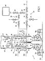
- FIG. 1 very schematically illustrates a gas incinerator device 1, which can be loaded on a vessel carrying liquefied gas or on a terminal gas off-shore.
- This incinerator device 1 comprises a single combustion chamber 3 comprising a heating body 5 producing combustion gases, at least one fan 7a, 7b supplying the heating body 5 with fresh air 9 to ensure combustion and an exhaust stack 11 of the mixture 13 formed by the combustion gases and the fresh air 9.
- the incinerator device 1 comprises two fans 7a and 7b disposed below and in the axis of the combustion chamber 3. These fans 7a and 7b can be actuated by two motors 13a and 13b.
- the fresh air 9 from the fans 7a, 7b is forced into the combustion chamber 3 via an air box 15.
- the air box 15 is connected to the fans 7a and 7b and to the exhaust stack 11 by flexible sleeves 17.
- check valves 19 are optionally placed at the outlet of the fans 7a, 7b, to guide all the fresh air 9 blown by the fan (s) 7a, 7b in operating condition to the combustion chamber 3.
- the combustion chamber 3 is mounted in the exhaust stack 11 so as to leave between the combustion chamber 3 and the exhaust stack 11 an annular duct 21 for the circulation of fresh air 9a. combustion and / or cooling from the fan or fans 7a, 7b.
- the combustion chamber 3 surrounding the heating body 5 comprises a plurality of orifices 29a and / or injection tubes 29b for injecting a portion of the fresh air 9a circulating in the annular duct 11 near the flame 31 of the heating body 5 and thus mix this fresh air with the combustion gases.
- the orifices 29a and injection tubes 29b inject the fresh air 9a directly into the hot vein mixing so this fresh air 9a in the hot vein. Note that the use of the same fans to feed the annular conduit 21 and the interior of the combustion chamber 3 simplifies and reduces the costs and power consumption of the installation.
- the combustion chamber 3 preferably having the same geometric shape (for example cylindrical) as the exhaust stack 11, is inserted directly into the lower part thereof. This makes it possible, among other things, to eliminate any high-temperature adaptation and coupling piece between the combustion chamber 3 and the exhaust stack 11.
- the annular duct 21 has a mechanical clearance facilitating the insertion and the mounting of the combustion chamber 3 in the exhaust stack 11.
- the chimney 11 is connected in the annular space 21 via a compensator comprising the flexible sleeves 17.
- a compensator operating at a temperature close to ambient (typically less than 100 ° C. ) allowing the use of inexpensive means such as reinforced canvas bellows.
- this presents little risk in case of leakage because this leak would be air which is also close to the ambient temperature.
- the fresh air 9a circulating in the annular duct 21 also serves to cool the walls of the combustion chamber 3, which allows to use for its production non-costly materials and does not need to be protected by a specific thermal insulation .
- the combustion chamber 3 is supplied with dilution and combustion air from below and additional dilution air at its periphery through the annular duct 21.
- the exhaust stack 11 can be supported or fixed on a first support 23a at an upper deck 24a of the ship.
- the combustion chamber 3, the heating body 5 and the air box 15 can be fixed on a second support 23b at an intermediate bridge 24b of the ship while the fans 7a and 7b can be fixed on a third support 23c at a lower bridge 24c.
- the chimney 11 supplied by the construction site is supported independently of the combustion chamber 3, the heating body 5, the air box 15 and the fans 7a, 7b which are equipment supplied by the manufacturer of the incinerator which simplifies the mechanical interfaces between the construction site and the equipment manufacturer.
- the discharge duct 11 being fixed on the first support 23a, drops sufficiently low around the combustion chamber 3 so that the flexible connection 17 connecting it to the air box 15 and the combustion chamber 3 mechanically connected the support 23b is not exposed to the hot gases 13 but the current of fresh air 9a flowing in the annular duct 21 thus created between the combustion chamber 3 and the chimney.
- the combustion chamber 3 can be suspended in the exhaust stack 11 by suspension means 25 preferably arranged in the less hot parts of the combustion chamber 3 and cooled by the fresh air 9a flowing in the duct annular 21.
- the exhaust stack 11, the combustion chamber 3, the heater 5 and the air box 15 can be fixed on the same support (23a or 23b) at the intermediate bridge or upper.
- the incinerator device 1 comprises a plurality of pipes or tubes 33 arranged above the combustion chamber 3 bringing additional fresh air 9b from the outside by a suction effect created by the fresh air 9 from of the fan or fans 7a, 7b.
- an additional portion of the dilution air is supplied to the core of the hot gases via the plurality of tubes 33 which are connected to the outside of the exhaust stack 11.
- These tubes 33 being of short length, typically the order of one fifth of the diameter of the exhaust stack 11, have for the sucked air, a small source of pressure loss and can therefore provide a very significant additional dilution air flow, typically from ten to twenty to hundred. This provision makes it possible to dispense with an arrangement of additional fans in the upper part of the combustion chamber 3, which simplifies the installation.
- the incinerator device 1 may comprise a turbulator 35 facilitating the mixing of the combustion gas with the fresh air.
- This turbulator 35 can be mounted on a part of the plurality of tubes 33.
- the turbulator 35 can be supported by some of these tubes 33 so that the fresh air 9b sucked by them can be used to cool it.
- the incinerator device 1 may comprise at least a first water circuit 37 comprising at its end a first spray nozzle 39 housed inside at least one tube of the plurality of tubes 33.
- the first spray nozzle 39 injects water into the mixture formed by the combustion gases and the fresh air for cool them by partial or complete evaporation.
- the incinerator device 1 may comprise an additional duct 41 mounted around an upper part of the exhaust duct 11 which, by suction effect, generates an additional air flow rate in the plume of hot gases.
- the incinerator device 1 may comprise a second water circuit 43 comprising at its end a second nozzle 45 spray nozzle housed inside this conduit 41 additional to obtain lower plume temperatures.
- the cooling of the walls of the combustion chamber 3 is ensured mainly by forced convective exchange on their outer face while the cooling of the hot gases is induced by the fresh air ducts 33 into the hot vein and then, possibly, by the injection via the circuits 37, 43 of water.
- the mixture of the additional fresh air and the water with the hot gases is ensured by the turbulences created by the fresh air and water injection ducts 29a, 29b and 37, 43, as well as by the turbulator 35.
- the pressure difference between the annular duct 21 and the inside of the combustion chamber 3 is very small, typically of the order of 100 Pa (1 mbar).
- the mixture of hot gases is ensured, from the bottom of the combustion chamber 3, by an air supply through the air box with a mixing ratio of the order of "70".
- the mixture of hot gases is provided by the turbulence and additional fresh air supply created by the tubes or orifices 29a, 29b, 33 or the turbulator 35.
- the burner is fed in excess, from below, in a ratio of about 70, the average temperature of the hot gases is reduced to below about 700 ° C.
- the temperature of the hot gases is reduced to a level below about 550 ° C, allowing the use of non-refractory materials for this chamber, such as stainless steel.
- the heater 5 comprises one or more burners 47 whose ignition is controlled by a flame detection system 49 comprising for example ultraviolet cells.
- a diaphragm 51 is placed at the burner or burners 47 to optimize the distribution of air around them and create turbulence to catch the flame.
- the heating body 5 is supplied with gas independently by a main circuit 53 with a high flow rate and a secondary circuit 55 with a low flow rate.
- the main 53 and secondary 55 circuits are fed by a line of gas 57 for example a ship (see Figure 2).
- the flow of gas sent to the incinerator device 1 from the gas line 57 is regulated by a control valve 59.
- the burner or burners 47 of the heating body 5 are fed from the gas line 57 by two branches corresponding to two different flow rates.
- the main branch or circuit 53 is controlled by first and second valves 61 and 63 whose closure is controlled by a detector or pressure sensor 65 in the event of failure of the fan (s) 7a, 7b or by the flame detector 49 in case non-ignition of the burner (s) 47.
- branch or secondary circuit 55 is controlled by third and fourth valves 67 and 69 whose closure is controlled by the pressure sensor 65 in the event of failure of the fan or fans 7a, 7b.
- the branch or main circuit 53 at high flow rate is used in normal operation, when the gas sent to the incinerator 1 is sufficiently rich in methane to allow its ignition by an igniter 71 (for example electric candles) and therefore its combustion and the creation of a flame 31 detectable by the flame detector 49.
- an igniter 71 for example electric candles
- the first and second valves 61 and 63 are closed and a safety valve 73 is open to evacuate the trapped gas between these two valves 61 and 63 to a vent.
- the device according to the invention makes it possible, when the main circuit 53 with a high flow rate is closed, to use the secondary circuit 55 which allows , to send a flow of gas mixture to the burner 47, even if this gas mixture is incombustible. Indeed, this gas mixture injected into the combustion chamber 3 is diluted with the air supplied by the fans 7a, 7b and the tubes 33 and leads 41. This further depletion of the methane content of the mixture ensures that this methane content of gas escaping from the exhaust stack 11 is well below the areas of explosivity.
- the igniter 71 may be regularly activated so as to re-ignite the mixture if it becomes fuel again, for example when a tank is tilted. one vessel filled with inert gas to another filled with natural gas vapors. If this combustion is maintained, the flame 31 can be detected again by the flame detector 49 again authorizing the opening of the first and second valves 61 and 63 of the main circuit 53 allowing a greater flow rate of treatment of the gases from the tanks .
- the security When the incinerator device 1 operates in dilution mode the security relies on the closing of the third and fourth valves 67 and 69 in the event of failure of the fans 7a, 7b not guaranteeing a sufficient dilution of the mixture.
- This security can be controlled by the pressure sensor 65 which measures the pressure drop between the fans 7a, 7b and the combustion chamber 3 at the diaphragm 51 placed near the burner 47.
- the safety of the incinerator device 1 is thus guaranteed at a low flow rate, by closing the third and fourth valves 67 and 69 and the opening of another venting valve 75 as soon as the pressure sensor 65 detects a pressure too low, and therefore an air flow too low to sufficiently dilute the gas mixture sent to the incinerator 1, it is sufficiently rich in methane or not to be burned or simply diluted.
- the maximum flow rate in the secondary circuit 55 can be controlled by a specific throttle or by the very choice of the section of the third and fourth valves 67 and 69.
- the dilution ratio in the combustion chamber 3 is such that a reignition of the gas mixture by the igniter 71, if this mixture becomes fuel again, remains non-hazardous .
- this secondary circuit 55 coupled with the igniter 71 acts as a pilot flame, which once activated and detected by the flame detector 49 serves to ignite the main flame 31 fed by the opening of the main circuit 53 controlled by the valves 61 and 63.
- the secondary circuit 55 can be used to treat by combustion and dilution the nitrogen-rich vapor fraction, which is not reliqued and returned to the vessels.
- the main circuit 53 is activated only in the event of failure of the reliquifier (or during its start or stop transients) when the incinerator 1 must burn some or all of the vapors coming from the vessels of the vessel. .
- the incinerator device 1 comprises a buffer tank 81 connected either to the gas line 57 by means of the fifth and sixth valves 83 and 85 to control the pressure, or with the heating body 5 by means of the third, fourth and fifth valves 67, 69 and 83 to be depressurized. This makes it possible to damp the gas flow transients to be treated by the incinerator 1.
- the buffer tank 81 can be isolated by the valve 83 while being mounted upstream of the valves 67 and 69. In addition, the buffer tank 81 can be coupled with the valve 85 placed between the main 53 and secondary 55 circuits. to use this buffer capacity not between the minimum and maximum pressure values of the gas line 57 but between this maximum pressure and a pressure slightly higher than the pressure in the combustion chamber 3.
- the nominal gas flow rate in the gas line 57 is adjusted by pressurizing and reheating systems (not shown) provided for this purpose to meet the needs of propulsion engines of the ship making zero the flow of gas to be treated by the incinerator 1. It is therefore interesting, to drastically reduce the power consumption of the incinerator, to be able to stop the fans 7a, 7b during this nominal regime of the system where there are no excess gas vapors to be eliminated.
- an alarm controlled by the pressure sensor 65 is raised and the valves 67 and 69 of the secondary circuit 55 can be opened and the igniter 71 activated. If the gas is sufficiently rich in methane, it starts to burn and another alarm controlled by the flame detector 49 can also be raised, allowing the opening of the main circuit 53 controlled by the valves 61 and 63.
- the incinerator 1 can operate at full power, depending on the gas flow rate to be treated to maintain the pressure in the gas line 57 in its nominal range.
- the valve 85 can then be closed, making it possible to isolate the reservoir 81 from the gas line 57 while maintaining it in connection with the burner 47 via the secondary circuit 55, the valves 67, 69 and 83 being kept open.
- the burner technology 47 Since the burner technology 47 is appropriately selected, it can operate with a very low pressure drop, typically less than 10 kPa. In this case, the gas absorbed in the buffer tank 81 can be discharged to the burner 47 until it reaches a pressure very close to that prevailing in the combustion chamber 3, itself close to the atmospheric pressure. When the pressure in the buffer tank 81 is brought to this value, the valves 67, 69 and 83 can be closed and the buffer tank 81 can be left closed on itself ready, to be used again to cope with a transition of pressure in the gas line 57.
- the operating pressure range of the buffer tank 81 which is between the maximum nominal pressure in the gas line 57 and the atmospheric pressure, is much wider than that of the tank of the prior art (see FIG. it is between the minimum and maximum pressures of the gas line.
- the nominal pressure in the gas line 57 varies between 0.6 and 0.8 MPa
- the pressure in the buffer tank 81 can vary between 0.8 MPa and atmospheric pressure. It can therefore be seen that, to absorb the same quantity of gas, the volume of the buffer tank 81 is about four times smaller than that of a reservoir of the prior art, which has a very significant advantage in terms of cost and efficiency. congestion.
- valves 87 or circuits (not shown) for injection of inert gas, for example nitrogen, can to be placed.
- valves 67, 69 and 57 can be closed and the fans 7a, 7b stopped again. It is thus possible, with a small buffer tank 81 to face the transient gas burning while minimizing the power consumption of the fans 7a, 7b.
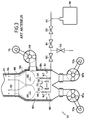
- FIG. 2 is a very diagrammatic view of a transport vessel having tanks 91 for liquefied gas, comprising an incinerator device according to FIG. 1, providing for the burning of the vapors escaping from the tanks.
- the exhaust stack 11 is mounted on the upper deck 24a and the fans 7a and 7b are mounted on the lower deck 24c of the ship.
- the combustion chamber 3, the heating body 5 and the air box 15 are mounted on the intermediate bridge 24b of the ship.
- the incinerator device can also be used in a gas terminal.
Landscapes
- Engineering & Computer Science (AREA)
- General Engineering & Computer Science (AREA)
- Mechanical Engineering (AREA)
- Environmental & Geological Engineering (AREA)
- Chemical & Material Sciences (AREA)
- Combustion & Propulsion (AREA)
- Incineration Of Waste (AREA)
- Furnace Details (AREA)
Applications Claiming Priority (1)
| Application Number | Priority Date | Filing Date | Title |
|---|---|---|---|
| FR0500631A FR2881209B1 (fr) | 2005-01-21 | 2005-01-21 | Incinerateur de gaz installe sur un navire de transport de gaz liquefie |
Publications (2)
| Publication Number | Publication Date |
|---|---|
| EP1684013A2 true EP1684013A2 (de) | 2006-07-26 |
| EP1684013A3 EP1684013A3 (de) | 2014-08-27 |
Family
ID=34955007
Family Applications (1)
| Application Number | Title | Priority Date | Filing Date |
|---|---|---|---|
| EP06290085.7A Withdrawn EP1684013A3 (de) | 2005-01-21 | 2006-01-13 | Abgasverbrennungsanlage für Flüssiggastransportschiff oder Flüssiggasterminal |
Country Status (6)
| Country | Link |
|---|---|
| US (1) | US7836835B2 (de) |
| EP (1) | EP1684013A3 (de) |
| JP (1) | JP4989078B2 (de) |
| KR (1) | KR101293003B1 (de) |
| CN (1) | CN100572919C (de) |
| FR (1) | FR2881209B1 (de) |
Cited By (1)
| Publication number | Priority date | Publication date | Assignee | Title |
|---|---|---|---|---|
| EP3249296A4 (de) * | 2015-02-27 | 2018-01-31 | Mitsubishi Heavy Industries, Ltd. | Vorrichtung zum verbrennen flüchtiger organischer verbindungen, kessel, tanker und verfahren zum verbrennen flüchtiger organischer verbindungen |
Families Citing this family (17)
| Publication number | Priority date | Publication date | Assignee | Title |
|---|---|---|---|---|
| KR20100072274A (ko) * | 2007-09-20 | 2010-06-30 | 어플라이드 머티어리얼스, 인코포레이티드 | 전자 장치 제조 폐기물의 대기 공기 정화를 위한 방법 및 장치 |
| GB0903990D0 (en) * | 2009-03-07 | 2009-04-22 | Hamworthy Combustion Eng Ltd | Incinerator |
| GB2471909C (en) * | 2009-07-18 | 2019-02-13 | Hamworthy Combustion Engineering Ltd | Incinerator for boil-off gas |
| NO20092951A1 (no) * | 2009-09-03 | 2011-03-04 | Viking Dredging As | Anordning ved bulkskip for sandtransport og fluidisert lossing |
| JP2013092053A (ja) | 2011-10-24 | 2013-05-16 | Mitsubishi Heavy Ind Ltd | 液化ガス処理システム、この制御方法、これを備えた液化ガス運搬船およびこれを備えた液化ガス貯蔵設備 |
| FR3012206B1 (fr) * | 2013-10-17 | 2015-11-06 | Nex Generation Natural Gas Natural Growth | Incinerateur de gaz compact embarque sur navire |
| FI20146081A7 (fi) * | 2014-12-10 | 2016-06-11 | Evac Oy | Aluksen jätteenkäsittelylaitos ja menetelmä pakokaasun jäähdyttämiseksi aluksen jätteenkäsittelylaitoksessa |
| KR20160086610A (ko) | 2015-01-12 | 2016-07-20 | 강림중공업 주식회사 | 버너 및 이를 이용한 증발가스 처리장치용 가스연소기 |
| KR101661173B1 (ko) | 2015-04-13 | 2016-09-29 | 강림중공업 주식회사 | 냉각구조의 소형 증발가스 처리장치용 연소기 |
| KR101661169B1 (ko) | 2015-04-13 | 2016-09-29 | 강림중공업 주식회사 | 증발가스 처리장치용 가스연소기 |
| KR101661172B1 (ko) | 2015-04-13 | 2016-09-29 | 강림중공업 주식회사 | 증발가스 처리장치용 가스연소기 |
| JP7152957B2 (ja) * | 2019-01-08 | 2022-10-13 | 三菱重工マリンマシナリ株式会社 | 舶用ボイラ及び舶用ボイラの改造方法 |
| KR102385753B1 (ko) * | 2020-05-25 | 2022-04-11 | 현대중공업 주식회사 | 가스연소유닛 및 이를 구비한 선박 |
| JP7311155B2 (ja) * | 2020-06-01 | 2023-07-19 | ボルカノ株式会社 | ガス燃焼装置 |
| CN113154368A (zh) * | 2021-06-04 | 2021-07-23 | 西安热工研究院有限公司 | 一种用于降低送风机和一次风机噪声的煤粉锅炉风机布置系统 |
| CN117167767A (zh) * | 2023-09-23 | 2023-12-05 | 中船九江海洋装备(集团)有限公司 | 一种船舶气体燃烧单元的多级供风装置 |
| FR3167992A1 (fr) | 2024-10-25 | 2026-05-01 | Eiffage Metal | Torchère fermée à combustion optimisée |
Citations (1)
| Publication number | Priority date | Publication date | Assignee | Title |
|---|---|---|---|---|
| DE10211645A1 (de) | 2002-03-15 | 2003-10-09 | Saacke Gmbh & Co Kg | Verfahren zum Verbrennen von Boil-off-Gas auf einem Flüssiggas-Transportschiff und Verwendung einer Combustor-Einheit |
Family Cites Families (47)
| Publication number | Priority date | Publication date | Assignee | Title |
|---|---|---|---|---|
| US1629251A (en) * | 1927-05-17 | Of astlebobo | ||
| US2702590A (en) * | 1949-09-08 | 1955-02-22 | Eloise B Stillman | Liquid fuel circulating system for mechanically atomizing liquid fuel burner and method of controlling the output of said burner |
| US2837893A (en) * | 1952-12-12 | 1958-06-10 | Phillips Petroleum Co | Automatic primary and secondary air flow regulation for gas turbine combustion chamber |
| US2979124A (en) * | 1958-09-29 | 1961-04-11 | American Air Filter Co | Air heater fuel control system |
| US3057983A (en) * | 1959-01-23 | 1962-10-09 | Westinghouse Electric Corp | Circuit interrupter |
| US3164201A (en) * | 1963-11-29 | 1965-01-05 | William R Irwin | High flame-low flame burners |
| US3548761A (en) * | 1968-12-26 | 1970-12-22 | Solomon Zalman | Anti-pollution incinerator |
| US3914090A (en) * | 1971-05-13 | 1975-10-21 | Engelhard Min & Chem | Method and furnace apparatus |
| DE2211264C3 (de) * | 1972-03-09 | 1981-07-02 | Klöckner-Humboldt-Deutz AG, 5000 Köln | Vorrichtung zur Erhöhung der Kühlwirkung eines Drehofen-Satellitenkühlers und Verfahren zum Betreiben derselben |
| US3797989A (en) * | 1972-11-20 | 1974-03-19 | Peabody Gordon Piatt | Burner control system |
| US3892519A (en) * | 1974-04-15 | 1975-07-01 | Zink Co John | Liquid bubble screen seal for controlling combustible gases |
| US4181491A (en) * | 1976-09-22 | 1980-01-01 | Bloom Engineering Company, Inc. | Method and apparatus for heating a furnace chamber |
| US4137036A (en) * | 1977-03-28 | 1979-01-30 | Combustion Unlimited Incorporated | Flare burner |
| JPS5739895U (de) * | 1980-08-19 | 1982-03-03 | ||
| DE3038519C2 (de) * | 1980-10-11 | 1983-08-18 | Hartung, Kuhn & Co Maschinenfabrik GmbH, 4000 Düsseldorf | Verfahren zur Verminderung der Feststoffemissionen während des Ausdrückens einer Kokscharge aus Horizontalkammeröfen und Kamin zur Durchführung des Verfahrens |
| HU184389B (en) * | 1981-02-27 | 1984-08-28 | Villamos Ipari Kutato Intezet | Method and apparatus for destroying wastes by using of plasmatechnic |
| JPS57165259U (de) * | 1981-04-08 | 1982-10-18 | ||
| JPS5849444Y2 (ja) * | 1981-06-11 | 1983-11-11 | 株式会社東芝 | ガス・バ−ナ |
| US4552082A (en) * | 1982-05-27 | 1985-11-12 | Grey Vincent G | Offshore incineration of hazardous waste materials |
| US4819438A (en) * | 1982-12-23 | 1989-04-11 | United States Of America | Steam cooled rich-burn combustor liner |
| JPS60200007A (ja) * | 1984-03-21 | 1985-10-09 | Sumitomo Metal Ind Ltd | 微粉炭燃焼方法 |
| US4632042A (en) * | 1985-10-30 | 1986-12-30 | Chang Shien F | Incinerator for the high speed combustion of waste products |
| US6293121B1 (en) * | 1988-10-13 | 2001-09-25 | Gaudencio A. Labrador | Water-mist blower cooling system and its new applications |
| GB8826909D0 (en) * | 1988-11-17 | 1988-12-21 | Booth G | Combustion apparatus |
| US5018547A (en) * | 1990-04-30 | 1991-05-28 | Alcorn Arlo S | Pressure actuated valve |
| US4981088A (en) * | 1990-05-14 | 1991-01-01 | Diamond Electronics, Inc. | Slag eliminator for furnace viewing system |
| TW211603B (de) * | 1991-06-03 | 1993-08-21 | Mitsubishi Heavy Ind Ltd | |
| US5397551A (en) * | 1992-07-09 | 1995-03-14 | Daesung Industrial Co., Ltd. | Incinerator |
| US5322026A (en) * | 1992-12-21 | 1994-06-21 | Bay Il H | Waste combustion chamber with tertiary burning zone |
| JPH06272833A (ja) * | 1993-03-17 | 1994-09-27 | Ryoji Watabe | 廃棄物焼却炉の次段燃焼室 |
| JP2764703B2 (ja) * | 1995-03-13 | 1998-06-11 | 有限会社ナカイ | ガス直火型かまどの排気構造 |
| JP3488337B2 (ja) * | 1996-03-29 | 2004-01-19 | 大陽東洋酸素株式会社 | 排ガス除害装置における燃焼ノズルと燃焼筒、排ガス除害装置及び排ガスの除害方法 |
| US5820736A (en) * | 1996-12-23 | 1998-10-13 | Bouziane; Richard | Pyrolysing apparatus |
| JP3725299B2 (ja) * | 1997-06-19 | 2005-12-07 | 株式会社パウダリングジャパン | 通常燃焼及びパルス燃焼両用燃焼器 |
| US6135063A (en) * | 1999-03-11 | 2000-10-24 | Welden; David P. | Dual regulator direct-fired steam generator |
| AU6890700A (en) * | 1999-07-29 | 2001-02-19 | Independent Stave Co. | Burners with high turndown ratio and gas combustor |
| JP3790393B2 (ja) * | 1999-11-05 | 2006-06-28 | 大阪瓦斯株式会社 | 液化天然ガス運搬船におけるカーゴタンクの圧力制御装置及びその圧力制御方法 |
| US6485292B1 (en) * | 1999-11-19 | 2002-11-26 | Process Equipment & Service Company, Inc. | Flare stack for natural gas dehydrators |
| JP2001269530A (ja) * | 2000-03-28 | 2001-10-02 | Sumitomo Heavy Ind Ltd | 水スプレー装置及びそれを備えるガス冷却システム |
| JP3844941B2 (ja) * | 2000-03-30 | 2006-11-15 | 株式会社神戸製鋼所 | 調温装置および高温排ガスの調温方法 |
| JP4535558B2 (ja) * | 2000-03-31 | 2010-09-01 | 大陽日酸株式会社 | 燃焼式排ガス処理装置 |
| JP4264792B2 (ja) * | 2000-12-19 | 2009-05-20 | 株式会社日立プラントテクノロジー | 排ガス冷却装置 |
| US6782906B2 (en) * | 2000-12-28 | 2004-08-31 | Young-Chul Chang | Time based mass flow controller and method for controlling flow rate using it |
| JP2002339071A (ja) * | 2001-05-18 | 2002-11-27 | L'air Liquide Sa Pour L'etude & L'exploitation Des Procede S Georges Claude | Alcvdシステムにおける処理ガス供給機構 |
| GB0120661D0 (en) * | 2001-08-24 | 2001-10-17 | Cryostar France Sa | Natural gas supply apparatus |
| US20030059731A1 (en) * | 2001-09-25 | 2003-03-27 | Coffey Clayton G. | Device for incinerating waste gas |
| US20050058959A1 (en) * | 2003-09-17 | 2005-03-17 | General Electric Company | Gas flow control for gas burners utilizing a micro-electro-mechanical valve |
-
2005
- 2005-01-21 FR FR0500631A patent/FR2881209B1/fr not_active Expired - Lifetime
-
2006
- 2006-01-13 EP EP06290085.7A patent/EP1684013A3/de not_active Withdrawn
- 2006-01-18 US US11/334,291 patent/US7836835B2/en not_active Expired - Fee Related
- 2006-01-20 JP JP2006012369A patent/JP4989078B2/ja not_active Expired - Lifetime
- 2006-01-20 KR KR1020060006277A patent/KR101293003B1/ko not_active Expired - Lifetime
- 2006-01-23 CN CNB2006100062376A patent/CN100572919C/zh not_active Expired - Lifetime
Patent Citations (1)
| Publication number | Priority date | Publication date | Assignee | Title |
|---|---|---|---|---|
| DE10211645A1 (de) | 2002-03-15 | 2003-10-09 | Saacke Gmbh & Co Kg | Verfahren zum Verbrennen von Boil-off-Gas auf einem Flüssiggas-Transportschiff und Verwendung einer Combustor-Einheit |
Cited By (1)
| Publication number | Priority date | Publication date | Assignee | Title |
|---|---|---|---|---|
| EP3249296A4 (de) * | 2015-02-27 | 2018-01-31 | Mitsubishi Heavy Industries, Ltd. | Vorrichtung zum verbrennen flüchtiger organischer verbindungen, kessel, tanker und verfahren zum verbrennen flüchtiger organischer verbindungen |
Also Published As
| Publication number | Publication date |
|---|---|
| CN1807980A (zh) | 2006-07-26 |
| JP4989078B2 (ja) | 2012-08-01 |
| US20060166152A1 (en) | 2006-07-27 |
| FR2881209B1 (fr) | 2015-04-24 |
| FR2881209A1 (fr) | 2006-07-28 |
| KR20060085202A (ko) | 2006-07-26 |
| US7836835B2 (en) | 2010-11-23 |
| CN100572919C (zh) | 2009-12-23 |
| EP1684013A3 (de) | 2014-08-27 |
| KR101293003B1 (ko) | 2013-08-02 |
| JP2006200885A (ja) | 2006-08-03 |
Similar Documents
| Publication | Publication Date | Title |
|---|---|---|
| EP1684013A2 (de) | Abgasverbrennungsanlage für Flüssiggastransportschiff oder Flüssiggasterminal | |
| CN101526217B (zh) | 燃气轮机及燃烧器的燃料供给方法 | |
| EP3156635B1 (de) | Raketentriebwerk mit vielseitigem zündbrenner | |
| CN106460671B (zh) | 气体涡轮发动机系统 | |
| FR2788112A1 (fr) | Appareil de type torchere et procede pour la combustion de gaz | |
| EP2546204A1 (de) | Verfahren und Installation zum Glasschmelzen | |
| EP2984386B1 (de) | Verbessertes system zur behandlung und zufuhr von erdgas mit einer schaltung zum erwärmen eines tanks | |
| EP1577530A1 (de) | Verfahren und Vorrichtung zur Zündung eines Nachverbrenner für Zweistromtriebwerk | |
| BE1028409B1 (fr) | Chambre de combustion sans flamme et appareil de production d'électricité ou de cogénération d'énergie associé | |
| WO2002097327A1 (fr) | Generateur thermique et procede de combustion permettant de limiter les emissions d'oxydes d'azote par recombustion des fumees | |
| FR2984958A1 (fr) | Event pour circuit d'alimentation en carburant gazeux d'une turbine a gaz, et procede associe | |
| FR3104647A1 (fr) | Dispositif d’allumage pour moteur-fusée | |
| EP4184059A1 (de) | Brennstoffkessel mit einer vorrichtung zur verringerung des drucks für die zündung der flamme | |
| CN117006474B (zh) | 一种利用船舶锅炉处理双壁管空气的系统 | |
| FR3110197A1 (fr) | Systeme de purge d’un combustible au gaz reactif | |
| JP7689667B1 (ja) | アンモニアを安全に貯蔵して燃焼させるシステムと方法 | |
| WO2026033931A1 (ja) | ガス燃料供給システム | |
| JP2025153094A (ja) | 燃焼システム | |
| KR20260007412A (ko) | 암모니아 연료 선박 | |
| FR3162424A1 (fr) | Système de sécurisation d’un circuit de fluide à risque et procédé associé | |
| FR2692966A1 (fr) | Dispositif de réchauffage par combustion de gaz chauds. | |
| FR3012206A1 (fr) | Incinerateur de gaz compact embarque sur navire | |
| FR2938049A1 (fr) | Rechauffeur de fluide combustible. | |
| FR3088989A1 (fr) | Torchère pour la combustion de gaz | |
| FR2710135A1 (fr) | Incinérateur à ordures ménagères et autres résidus. |
Legal Events
| Date | Code | Title | Description |
|---|---|---|---|
| PUAI | Public reference made under article 153(3) epc to a published international application that has entered the european phase |
Free format text: ORIGINAL CODE: 0009012 |
|
| AK | Designated contracting states |
Kind code of ref document: A2 Designated state(s): AT BE BG CH CY CZ DE DK EE ES FI FR GB GR HU IE IS IT LI LT LU LV MC NL PL PT RO SE SI SK TR |
|
| AX | Request for extension of the european patent |
Extension state: AL BA HR MK YU |
|
| RAP1 | Party data changed (applicant data changed or rights of an application transferred) |
Owner name: ALFA LAVAL AALBORG A/S |
|
| RIC1 | Information provided on ipc code assigned before grant |
Ipc: F23G 7/08 20060101AFI20140514BHEP Ipc: B63J 4/00 20060101ALI20140514BHEP Ipc: F23L 9/04 20060101ALI20140514BHEP Ipc: F23L 7/00 20060101ALI20140514BHEP |
|
| PUAL | Search report despatched |
Free format text: ORIGINAL CODE: 0009013 |
|
| AK | Designated contracting states |
Kind code of ref document: A3 Designated state(s): AT BE BG CH CY CZ DE DK EE ES FI FR GB GR HU IE IS IT LI LT LU LV MC NL PL PT RO SE SI SK TR |
|
| AX | Request for extension of the european patent |
Extension state: AL BA HR MK YU |
|
| AKY | No designation fees paid | ||
| AXX | Extension fees paid |
Extension state: BA Extension state: HR Extension state: AL Extension state: MK Extension state: YU |
|
| REG | Reference to a national code |
Ref country code: DE Ref legal event code: R108 |
|
| STAA | Information on the status of an ep patent application or granted ep patent |
Free format text: STATUS: THE APPLICATION IS DEEMED TO BE WITHDRAWN |
|
| 18D | Application deemed to be withdrawn |
Effective date: 20150228 |