EP1680239B1 - Walzwerk, bestehend aus horizontalgerüsten und vertikalgerüsten - Google Patents
Walzwerk, bestehend aus horizontalgerüsten und vertikalgerüsten Download PDFInfo
- Publication number
- EP1680239B1 EP1680239B1 EP04790505A EP04790505A EP1680239B1 EP 1680239 B1 EP1680239 B1 EP 1680239B1 EP 04790505 A EP04790505 A EP 04790505A EP 04790505 A EP04790505 A EP 04790505A EP 1680239 B1 EP1680239 B1 EP 1680239B1
- Authority
- EP
- European Patent Office
- Prior art keywords
- horizontal
- vertical
- stand
- rolling mill
- connecting elements
- Prior art date
- Legal status (The legal status is an assumption and is not a legal conclusion. Google has not performed a legal analysis and makes no representation as to the accuracy of the status listed.)
- Expired - Lifetime
Links
Images

Classifications
-
- B—PERFORMING OPERATIONS; TRANSPORTING
- B21—MECHANICAL METAL-WORKING WITHOUT ESSENTIALLY REMOVING MATERIAL; PUNCHING METAL
- B21B—ROLLING OF METAL
- B21B13/00—Metal-rolling stands, i.e. an assembly composed of a stand frame, rolls, and accessories
- B21B13/08—Metal-rolling stands, i.e. an assembly composed of a stand frame, rolls, and accessories with differently-directed roll axes, e.g. for the so-called "universal" rolling process
- B21B13/12—Metal-rolling stands, i.e. an assembly composed of a stand frame, rolls, and accessories with differently-directed roll axes, e.g. for the so-called "universal" rolling process axes being arranged in different planes
-
- B—PERFORMING OPERATIONS; TRANSPORTING
- B21—MECHANICAL METAL-WORKING WITHOUT ESSENTIALLY REMOVING MATERIAL; PUNCHING METAL
- B21B—ROLLING OF METAL
- B21B31/00—Rolling stand structures; Mounting, adjusting, or interchanging rolls, roll mountings, or stand frames
- B21B31/02—Rolling stand frames or housings; Roll mountings ; Roll chocks
-
- B—PERFORMING OPERATIONS; TRANSPORTING
- B21—MECHANICAL METAL-WORKING WITHOUT ESSENTIALLY REMOVING MATERIAL; PUNCHING METAL
- B21B—ROLLING OF METAL
- B21B1/00—Metal-rolling methods or mills for making semi-finished products of solid or profiled cross-section; Sequence of operations in milling trains; Layout of rolling-mill plant, e.g. grouping of stands; Succession of passes or of sectional pass alternations
- B21B1/02—Metal-rolling methods or mills for making semi-finished products of solid or profiled cross-section; Sequence of operations in milling trains; Layout of rolling-mill plant, e.g. grouping of stands; Succession of passes or of sectional pass alternations for rolling heavy work, e.g. ingots, slabs, blooms, or billets, in which the cross-sectional form is unimportant ; Rolling combined with forging or pressing
- B21B1/06—Metal-rolling methods or mills for making semi-finished products of solid or profiled cross-section; Sequence of operations in milling trains; Layout of rolling-mill plant, e.g. grouping of stands; Succession of passes or of sectional pass alternations for rolling heavy work, e.g. ingots, slabs, blooms, or billets, in which the cross-sectional form is unimportant ; Rolling combined with forging or pressing in a non-continuous process, e.g. triplet mill, reversing mill
-
- B—PERFORMING OPERATIONS; TRANSPORTING
- B21—MECHANICAL METAL-WORKING WITHOUT ESSENTIALLY REMOVING MATERIAL; PUNCHING METAL
- B21B—ROLLING OF METAL
- B21B13/00—Metal-rolling stands, i.e. an assembly composed of a stand frame, rolls, and accessories
- B21B13/02—Metal-rolling stands, i.e. an assembly composed of a stand frame, rolls, and accessories with axes of rolls arranged horizontally
-
- B—PERFORMING OPERATIONS; TRANSPORTING
- B21—MECHANICAL METAL-WORKING WITHOUT ESSENTIALLY REMOVING MATERIAL; PUNCHING METAL
- B21B—ROLLING OF METAL
- B21B13/00—Metal-rolling stands, i.e. an assembly composed of a stand frame, rolls, and accessories
- B21B13/06—Metal-rolling stands, i.e. an assembly composed of a stand frame, rolls, and accessories with axes of rolls arranged vertically, e.g. edgers
Definitions
- the invention relates to a rolling mill, comprising at least one horizontal frame and at least one vertical frame, which are interconnected.
- a rolling mill in which arranged in front of and behind a horizontal frame in each case a vertical frame and the front and rear vertical frame is connected to the centrally arranged horizontal frame, is for example from the document JP-A 55 144 308 known. Furthermore, from the JP-A 55 100 807 Connections of vertical scaffolding - horizontal scaffold - Vertical scaffold known by connecting bolts connect all three scaffolds together.
- FIGS. 2 and 3 show connections in which rods with end-side threads permit joining of these three units by common bores in both vertical frameworks and the horizontal framework arranged therebetween.
- the horizontal frame arranged in the middle is fastened by means of screws to the right and left arranged vertical stands.
- a further connection execution show the figures 9 and 10. Then care of the Ends recessed or provided with clamping edges bar for a clamping connection between the rolling stands.
- connections in which projections formed on the vertical frame stand surround a wedge formed on the horizontal frame stand.
- the clasps form column, in which wedges are introduced to brace the vertical frame with the horizontal frame together.
- the projections of the vertical frame stand flange plates, which are bolted to the horizontal frame stands.
- the greatest damage which can occur on a vertical stand is produced when the rolling stock is conveyed from a horizontal stand against the closed rolling gap of a vertical stand. From rolling force and rolling moment on the horizontal framework as well as geometry and material characteristics of the rolling stock, the horizontal force can be determined, with which the rolling stock is conveyed against the rolls of the vertical stand. The occurring horizontal maximum force is called a crash load. In order to prevent or avert damage or damage to the entire rolling mill, such a crash load must be recorded in the uprights of the vertical and / or horizontal stands.
- the invention is therefore based on the object pretending a connection between at least one horizontal frame and at least one vertical frame, which can accommodate such a crash load, designed to save space and designed to be detachable.
- connecting elements are detachably arranged between the two frameworks, wherein the connecting elements consist of a right flange, a left flange and a web arranged therebetween.
- connecting element is a slim and lightweight design. That The individual fasteners can be mounted without great effort or attached between the scaffolding. Furthermore, the space requirement of the connecting elements is very low, which allows a free space for installation space for other plant components, in particular a piping.
- the design of the connecting elements i. The dimensioning takes place with knowledge of the largest horizontal force ever to be taken into account in such a way that a crash load can be absorbed by the connected scaffolds without initiating the crash load into the foundation connection.
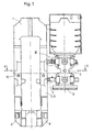
- a horizontal frame 1 is shown with a vertical frame 2 connected thereto.
- the horizontal frame 1 consists of a front 3 and rear 4 frame stand (Fig. 2), on whose respective right side rails 5, 6 a vertical frame 2 is fastened with connecting elements 7.
- the lower edge 8 of the horizontal frame stand 1 and the lower edge 9 of the vertical framework stand are arranged and fixed on a foundation (not shown).
- the connecting elements 7 are respectively provided on the right leg bars 5, 6 of the front and rear frame stand 3, 4 of a horizontal frame 1 above and below a rolling line 10. In the illustrated embodiment, the connecting elements 7 are screwed to the horizontal frame 1.
- Fig. 2 shows the connecting elements 7, which in T-shaped grooves 11, which are vertically introduced in the vertical frame 2, are guided.
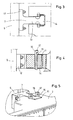
- the connecting elements 7 consist, as shown in Fig. 3, of a left flange 12, a web 13 and a right flange 14, wherein the left flange 12 is fixed by means of screws to the uprights 5 of the scaffold stand 3.
- Fig. 4 shows the same connection as in Fig. 3, but in a partially sectioned side view.
- tangential wedges 15, 16 are introduced. By a longitudinal displacement of both tangential wedges 15, 16 to each other, the total thickness of the wedge pair is increased and achieved a backlash-free connection of the horizontal frame 1 with the vertical frame 2. The position of the tangential wedges 15, 16 is secured by a screw 17.
Landscapes
- Engineering & Computer Science (AREA)
- Mechanical Engineering (AREA)
- Metal Rolling (AREA)
- Mutual Connection Of Rods And Tubes (AREA)
- Crushing And Grinding (AREA)
- Reduction Rolling/Reduction Stand/Operation Of Reduction Machine (AREA)
- Other Liquid Machine Or Engine Such As Wave Power Use (AREA)
Description
- Die Erfindung betrifft ein Walzwerk, bestehend aus mindestens einem Horizontalgerüst und mindestens einem Vertikalgerüst, welche miteinander verbunden sind.
- Beim Walzen von beispielsweise Brammen ist es bekannt, direkt im Anschluss von einem Horizontalgerüst zum Verringern der Dicke einer Bramme ein Vertikalgerüst vorzusehen, um die Breite einer Bramme zu reduzieren. Je nach Walzwerk folgen weitere Horizontal- und / oder Vertikalgerüste. Weiterhin bekannt ist, die Horizontal- und / oder Vertikalgerüste form- und / oder kraftschlüssig miteinander zu verbinden. Eine derartige Verbindung dient einerseits dazu, Schwingungen in einem Walzwerk zu minimieren und ermöglicht andererseits, eine größere Basis für die Anbindung beider Gerüste an ein Fundament, auf welches das Walzwerk mit seinen Horizontal- und Vertikalgerüsten aufgestellt und befestigt wird, zu bilden.
- Ein Walzwerk, bei dem vor und hinter einem Horizontalgerüst jeweils ein Vertikalgerüst angeordnet und das vordere und hintere Vertikalgerüst mit dem mittig angeordneten Horizontalgerüst verbunden ist, ist beispielsweise aus der Schrift
JP-A 55 144 308 JP-A 55 100 807 - Weiterhin bekannt sind Verbindungen, bei dem am Vertikalgerüstständer ausgebildete Auskragungen einen am Horizontalgerüstständer ausgebildeten Keil umgreifen. Die Umgreifungen bilden Spalte aus, in welche Keile eingebracht werden um das Vertikalgerüst mit dem Horizontalgerüst miteinander zu verspannen. Bei einer andere Ausführung bilden die Auskragungen des Vertikalgerüstständer Flanschplatten, welche an den Horizontalgerüstständern verschraubt werden.
- Beim Walzen von Walzgut entsteht der größte Schaden, welcher an einem Vertikalgerüst auftreten kann, dann, wenn das Walzgut aus einem Horizontalgerüst gegen den geschlossenen Walzspalt eines Vertikalgerüstes gefördert wird. Aus Walzkraft und Walzmoment am Horizontalgerüst sowie Geometrie und Werkstoffkennwerten des Walzgutes lässt sich die Horizontalkraft ermitteln, mit der das Walzgut gegen die Walzen des Vertikalgerüstes gefördert wird. Die dabei auftretende horizontale Maximalkraft wird als Crashload bezeichnet. Um eine Beschädigung bzw. einen Schaden an dem gesamten Walzwerk zu verhindern bzw. abzuwenden, muss ein solcher Crashload in den Ständern der Vertikal- und / oder Horizontalgerüste aufgenommen werden.
- Der Erfindung liegt daher die Aufgabe zugrunde, eine Verbindung zwischen mindestens einem Horizontalgerüst und mindestens einem Vertikalgerüst vorzugeben, welche einen solchen Crashload aufnehmen kann, platzsparend gestaltet und lösbar ausgebildet ist.
- Die Erfindung wird erfindungsgemäß dadurch gelöst, dass zwischen beiden Gerüsten Verbindungselemente lösbar angeordnet sind, wobei die Verbindungselemente aus einem rechten Flansch, einem linken Flansch und einem dazwischen angeordneten Steg bestehen.
- Ausgestaltungen der Erfindung sind in den Unteransprüchen angegeben.
- Mit dem erfindungsgemäß ausgebildeten Verbindungselement liegt eine schlanke und leichte Bauweise vor. D.h. die einzelnen Verbindungselemente können ohne großen Kraftaufwand montiert bzw. zwischen den Gerüsten befestigt werden. Weiterhin ist der Raumbedarf der Verbindungselemente sehr gering, welches ein Freihalten von Bauräumen für andere Anlagenbauteile, insbesondere einer Verrohrung, zulässt. Durch den Einsatz der erfindungsgemäßen Verbindungselemente erfolgt eine spiel- und spannungsfreie Verbindung der Gerüste. Die Auslegung der Verbindungselemente, d.h. die Dimensionierung erfolgt in Kenntnis der größten, jemals zu berücksichtigenden Horizontalkraft so, dass ein Crashload durch die verbundenen Gerüste aufgenommen werden kann, ohne dass eine Einleitung des Crashload in die Fundamentanbindung erfolgt.
- Weitere Einzelheiten der Erfindung ergeben sich aus den Ansprüchen und der nachfolgenden Beschreibung, in der ein in den Zeichnungen sehr schematisch dargestelltes Ausführungsbeispiel des Gegenstandes der Erfindung nähre erläutert wird. Es zeigen:
- Fig. 1
- eine Seitenansicht eines Horizontalgerüstes mit einem verbundenden Vertikalgerüst;
- Fig. 2
- eine Draufsicht im Schnitt auf die verbundenden Gerüste aus Fig. 1 entlang der Linie K - K;
- Fig. 3
- als Einzelteil (III) ein Verbindungselement in Draufsicht;
- Fig. 4
- als Einzelteil (IV) ein Verbindungselement in teilweise geschnittener Seitenansicht und
- Fig. 5
- ein Verbindungselement zwischen zwei Gerüsten in perspektivischer Darstellung.
- In Fig. 1 ist ein Horizontalgerüst 1 mit einem damit verbundenen Vertikalgerüst 2 dargestellt. Das Horizontalgerüst 1 besteht aus einem vorderen 3 und hinteren 4 Gerüstständer (Fig. 2), an dessen jeweils rechten Ständerholmen 5, 6 ein Vertikalgerüst 2 mit Verbindungselementen 7 befestigt ist. Die Unterkante 8 der Horizontalgerüstständer 1 und die Unterkante 9 der Vertikalgerüstständer sind auf einem Fundament (nicht dargestellt) angeordnet und befestigt.
- Die Verbindungselemente 7 sind jeweils an den rechten Ständerholmen 5, 6 der vorderen und hinteren Gerüstständer 3, 4 eines Horizontalgerüstes 1 oberhalb und unterhalb einer Walzlinie 10 vorgesehen. In der dargestellten Ausführung sind die Verbindungselemente 7 mit dem Horizontalgerüst 1 verschraubt.
- Fig. 2 zeigt die Verbindungselemente 7, welche in T-förmigen Nuten 11, die in dem Vertikalgerüst 2 vertikal eingebracht sind, geführt werden.
- Die Verbindungselemente 7 bestehen, wie in Fig. 3 dargestellt, aus einem linken Flansch 12, einem Steg 13 und einem rechten Flansch 14, wobei der linke Flansch 12 mittels Schrauben an dem Ständerholm 5 des Gerüstständers 3 befestigt ist.
- Fig. 4 zeigt dieselbe Verbindung wie in Fig. 3, allerdings in teilweise geschnittener Seitenansicht. Um das Spiel zwischen dem rechten Flansch 14 und der T-förmigen Nut 11 zu reduzieren werden Tangentialkeile 15, 16 eingebracht. Durch eine Längsverschiebung beider Tangentialkeile 15, 16 zueinander wird die Gesamtdicke des Keilpaares vergrößert und eine spielfreie Verbindung des Horizontalgerüstes 1 mit dem Vertikalgerüst 2 erreicht. Die Position der Tangentialkeile 15, 16 wird durch eine Schraubverbindung 17 gesichert.
- Die Anordnung der Tangentialkeile 15, 16 in der T-förmigen Nut 11 des Vertikalgerüstes 2 ist in Fig. 5 perspektivisch dargestellt.
Claims (7)
- Walzwerk, bestehend aus mindestens einem Horizontalgerüst (1) und mindestens einem Vertikalgerüst (2), welche miteinander verbunden sind,
dadurch gekennzeichnet,
dass zwischen beiden Gerüsten (1, 2) Verbindungselemente (7) lösbar angeordnet sind, wobei die Verbindungselemente (7) aus einem linken Flansch (12), einem rechten Flansch (14) und einem dazwischen angeordneten Steg (13) bestehen. - Walzwerk nach Anspruch 1,
dadurch gekennzeichnet,
dass die Flansche (12, 14) der Verbindungselemente (7) mit dem Horizontalgerüst (1) und dem Vertikalgerüst (2) verschraubt sind. - Walzwerk nach Anspruch 1,
dadurch gekennzeichnet,
dass ein Flansch (12, 14) an dem Horizontalgerüst (1) oder dem Vertikalgerüst (2) verschraubt ist und der andere Flansch (12, 14) in einer T-förmig ausgeformten Nut (11) des anderen Gerüstes (1, 2) geführt und verkeilt wird. - Walzwerk nach Anspruch 1,
dadurch gekennzeichnet,
dass beide Flansche (12, 14) in T-förmig ausgebildeten Nuten (11) an dem Horizontal- und Vertikalgerüsten (1, 2) geführt und verkeilt werden. - Walzwerk nach einem der Ansprüche 1 bis 4,
dadurch gekennzeichnet,
dass die Verbindungselemente (7) nur oberhalb oder nur unterhalb oder ober- und unterhalb einer Walzlinie (10) angeordnet sind. - Walzwerk nach einem der Ansprüche 1 bis 5,
dadurch gekennzeichnet,
dass die Verbindungselemente (7) spannungsfrei eingebaut werden. - Walzwerk nach einem der Ansprüche 3 bis 6,
dadurch gekennzeichnet,
dass beim Verkeilen der Flansche (12, 14) Tangentialkeile (15, 16) verwendet werden.
Applications Claiming Priority (2)
| Application Number | Priority Date | Filing Date | Title |
|---|---|---|---|
| DE10351900A DE10351900A1 (de) | 2003-11-06 | 2003-11-06 | Walzwerk, bestehend aus Horizontalgerüsten und Vertikalgerüsten |
| PCT/EP2004/011666 WO2005046895A1 (de) | 2003-11-06 | 2004-10-15 | Walzwerk, bestehend aus horizontalgerüsten und vertikalgerüsten |
Publications (2)
| Publication Number | Publication Date |
|---|---|
| EP1680239A1 EP1680239A1 (de) | 2006-07-19 |
| EP1680239B1 true EP1680239B1 (de) | 2007-12-05 |
Family
ID=34559416
Family Applications (1)
| Application Number | Title | Priority Date | Filing Date |
|---|---|---|---|
| EP04790505A Expired - Lifetime EP1680239B1 (de) | 2003-11-06 | 2004-10-15 | Walzwerk, bestehend aus horizontalgerüsten und vertikalgerüsten |
Country Status (9)
| Country | Link |
|---|---|
| US (1) | US7316144B2 (de) |
| EP (1) | EP1680239B1 (de) |
| JP (1) | JP4818926B2 (de) |
| CN (1) | CN100374220C (de) |
| AT (1) | ATE380076T1 (de) |
| DE (2) | DE10351900A1 (de) |
| RU (1) | RU2351416C2 (de) |
| UA (1) | UA83089C2 (de) |
| WO (1) | WO2005046895A1 (de) |
Families Citing this family (1)
| Publication number | Priority date | Publication date | Assignee | Title |
|---|---|---|---|---|
| IT1399421B1 (it) * | 2010-04-08 | 2013-04-16 | Danieli Off Mecc | Telaio di supporto per rulli di una gabbia di laminazione e gabbia di laminazione provvista di tale telaio |
Family Cites Families (13)
| Publication number | Priority date | Publication date | Assignee | Title |
|---|---|---|---|---|
| US186561A (en) * | 1877-01-23 | Improvement in machines for rolling hoop-iron | ||
| US694722A (en) * | 1899-06-16 | 1902-03-04 | Coe Brass Mfg Company | Machine for rolling metal forms. |
| US1385644A (en) * | 1920-01-15 | 1921-07-26 | Alvin L Roberts | Universal mill |
| US2089311A (en) * | 1933-12-18 | 1937-08-10 | Waterbury Farrel Foundry Co | Tandem mill |
| JPS531739B2 (de) * | 1972-09-25 | 1978-01-21 | ||
| JPS59284B2 (ja) * | 1979-01-24 | 1984-01-06 | 石川島播磨重工業株式会社 | 水平ロ−ルと竪ロ−ルを一体的に組込んだ圧延機 |
| JPS55126307A (en) * | 1979-03-23 | 1980-09-30 | Nippon Steel Corp | Rolling mill stand |
| JPS6019762Y2 (ja) * | 1979-04-26 | 1985-06-14 | 石川島播磨重工業株式会社 | 圧延機 |
| JPS55144308A (en) * | 1979-04-26 | 1980-11-11 | Ishikawajima Harima Heavy Ind Co Ltd | Rolling mill |
| JPS5849334B2 (ja) * | 1979-05-01 | 1983-11-04 | 石川島播磨重工業株式会社 | 圧延機 |
| GB2087281B (en) | 1980-11-17 | 1984-08-22 | Davy Loewy Ltd | Triplet roling mill |
| US4587823A (en) * | 1982-12-08 | 1986-05-13 | Blaw-Knox Corporation | Apparatus and method for press-edging hot slabs |
| DE20010915U1 (de) | 2000-06-20 | 2001-10-25 | Pies, Gerrit, 42699 Solingen | Nutseitiger Befestigungspartner einer Befestigungspaarung an einer T-Nut |
-
2003
- 2003-11-06 DE DE10351900A patent/DE10351900A1/de not_active Withdrawn
-
2004
- 2004-10-15 RU RU2006119629/02A patent/RU2351416C2/ru active
- 2004-10-15 US US10/575,146 patent/US7316144B2/en not_active Expired - Lifetime
- 2004-10-15 CN CNB2004800324946A patent/CN100374220C/zh not_active Expired - Fee Related
- 2004-10-15 DE DE502004005667T patent/DE502004005667D1/de not_active Expired - Lifetime
- 2004-10-15 WO PCT/EP2004/011666 patent/WO2005046895A1/de not_active Ceased
- 2004-10-15 UA UAA200606219A patent/UA83089C2/ru unknown
- 2004-10-15 EP EP04790505A patent/EP1680239B1/de not_active Expired - Lifetime
- 2004-10-15 AT AT04790505T patent/ATE380076T1/de active
- 2004-10-15 JP JP2006537120A patent/JP4818926B2/ja not_active Expired - Fee Related
Also Published As
| Publication number | Publication date |
|---|---|
| RU2006119629A (ru) | 2007-12-20 |
| CN1874856A (zh) | 2006-12-06 |
| ATE380076T1 (de) | 2007-12-15 |
| JP2007509757A (ja) | 2007-04-19 |
| WO2005046895A1 (de) | 2005-05-26 |
| US20070033978A1 (en) | 2007-02-15 |
| UA83089C2 (ru) | 2008-06-10 |
| CN100374220C (zh) | 2008-03-12 |
| DE10351900A1 (de) | 2005-06-09 |
| RU2351416C2 (ru) | 2009-04-10 |
| DE502004005667D1 (de) | 2008-01-17 |
| US7316144B2 (en) | 2008-01-08 |
| JP4818926B2 (ja) | 2011-11-16 |
| EP1680239A1 (de) | 2006-07-19 |
Similar Documents
| Publication | Publication Date | Title |
|---|---|---|
| EP0291719B1 (de) | Universalwalzgerüst mit anstellbaren Horizontal- und Vertikalwalzensätzen | |
| DE3247231A1 (de) | Rahmenkonstruktion fuer einen personen-schraegfoerderer | |
| DE4340313A1 (de) | Walzgerüst | |
| EP0513946B1 (de) | Vorrichtung zum Angleichen der Oberkante der unteren Arbeitswalze an die Walzlinie | |
| EP0851075A1 (de) | Erhöhte Plattform oder Bühne, insbesondere ausgebildet als Deckenschalung für das Betonieren | |
| DE4201958A1 (de) | Traggeruest | |
| DE59806383C5 (de) | Walzstrasse | |
| DE10103683B4 (de) | Walzvorrichtung für Walzstraßen mit gestaffelten Gerüsten, insbesondere Tandemwalzanlage | |
| DE3406659A1 (de) | Universal-walzgeruest mit offenen staendern, das in ein duo-walzgeruest und umgekehrt umwandelbar sowie in der hoehe und in der breite erweiterbar ist, zum walzen von profilstahl wie h- und i-traegern, schienen, spundwandstaehlen und anderen aehnlichen profilen | |
| EP2121210B1 (de) | Walzgerüst | |
| DE1129441B (de) | Universalwalzgeruest | |
| DE10351900A1 (de) | Walzwerk, bestehend aus Horizontalgerüsten und Vertikalgerüsten | |
| EP0809546B1 (de) | Walzenständer in geschlossener rahmenbauweise | |
| EP0949017B1 (de) | Universalwalzgerüst | |
| EP0955420A2 (de) | Fassadenprofil | |
| EP0599302B1 (de) | Gerüstständer | |
| DE3722706A1 (de) | Walzgeruest mit zwei oder mehr paaren von walzenstaendern | |
| DE1552929A1 (de) | Rollenrichtmaschine | |
| AT408316B (de) | Ständer für ein walzgerüst | |
| DE10241119C5 (de) | Presse, insbesondere Ein- oder Mehretagenpresse, kontinuierliche Presse, o. dgl. | |
| EP0803018B1 (de) | Rahmenadapter für gerüstgruppen | |
| EP0484781B1 (de) | Brammen-Stauchpresse für Warmbreitband-Walzwerke | |
| EP3427851A1 (de) | Konstruktionsprofil sowie kombinationsprofil bestehend aus mindestens zwei konstruktionsprofilen und geländerstütze | |
| AT211768B (de) | Universalwalzgerüst | |
| DE3532894C2 (de) |
Legal Events
| Date | Code | Title | Description |
|---|---|---|---|
| PUAI | Public reference made under article 153(3) epc to a published international application that has entered the european phase |
Free format text: ORIGINAL CODE: 0009012 |
|
| 17P | Request for examination filed |
Effective date: 20060117 |
|
| AK | Designated contracting states |
Kind code of ref document: A1 Designated state(s): AT BE BG CH CY CZ DE DK EE ES FI FR GB GR HU IE IT LI LU MC NL PL PT RO SE SI SK TR |
|
| DAX | Request for extension of the european patent (deleted) | ||
| GRAP | Despatch of communication of intention to grant a patent |
Free format text: ORIGINAL CODE: EPIDOSNIGR1 |
|
| RTI1 | Title (correction) |
Free format text: ROLL MILL CONSISTING OF HORIZONTAL FRAMES AND VERTICAL FRAMES |
|
| GRAS | Grant fee paid |
Free format text: ORIGINAL CODE: EPIDOSNIGR3 |
|
| GRAA | (expected) grant |
Free format text: ORIGINAL CODE: 0009210 |
|
| AK | Designated contracting states |
Kind code of ref document: B1 Designated state(s): AT BE BG CH CY CZ DE DK EE ES FI FR GB GR HU IE IT LI LU MC NL PL PT RO SE SI SK TR |
|
| REG | Reference to a national code |
Ref country code: GB Ref legal event code: FG4D Free format text: NOT ENGLISH |
|
| REG | Reference to a national code |
Ref country code: IE Ref legal event code: FG4D Free format text: LANGUAGE OF EP DOCUMENT: GERMAN |
|
| REG | Reference to a national code |
Ref country code: CH Ref legal event code: EP |
|
| REF | Corresponds to: |
Ref document number: 502004005667 Country of ref document: DE Date of ref document: 20080117 Kind code of ref document: P |
|
| GBT | Gb: translation of ep patent filed (gb section 77(6)(a)/1977) |
Effective date: 20080312 |
|
| PG25 | Lapsed in a contracting state [announced via postgrant information from national office to epo] |
Ref country code: SE Free format text: LAPSE BECAUSE OF FAILURE TO SUBMIT A TRANSLATION OF THE DESCRIPTION OR TO PAY THE FEE WITHIN THE PRESCRIBED TIME-LIMIT Effective date: 20080305 Ref country code: NL Free format text: LAPSE BECAUSE OF FAILURE TO SUBMIT A TRANSLATION OF THE DESCRIPTION OR TO PAY THE FEE WITHIN THE PRESCRIBED TIME-LIMIT Effective date: 20071205 Ref country code: ES Free format text: LAPSE BECAUSE OF FAILURE TO SUBMIT A TRANSLATION OF THE DESCRIPTION OR TO PAY THE FEE WITHIN THE PRESCRIBED TIME-LIMIT Effective date: 20080316 |
|
| PG25 | Lapsed in a contracting state [announced via postgrant information from national office to epo] |
Ref country code: FI Free format text: LAPSE BECAUSE OF FAILURE TO SUBMIT A TRANSLATION OF THE DESCRIPTION OR TO PAY THE FEE WITHIN THE PRESCRIBED TIME-LIMIT Effective date: 20071205 Ref country code: SI Free format text: LAPSE BECAUSE OF FAILURE TO SUBMIT A TRANSLATION OF THE DESCRIPTION OR TO PAY THE FEE WITHIN THE PRESCRIBED TIME-LIMIT Effective date: 20071205 Ref country code: PL Free format text: LAPSE BECAUSE OF FAILURE TO SUBMIT A TRANSLATION OF THE DESCRIPTION OR TO PAY THE FEE WITHIN THE PRESCRIBED TIME-LIMIT Effective date: 20071205 |
|
| NLV1 | Nl: lapsed or annulled due to failure to fulfill the requirements of art. 29p and 29m of the patents act | ||
| ET | Fr: translation filed | ||
| PG25 | Lapsed in a contracting state [announced via postgrant information from national office to epo] |
Ref country code: SK Free format text: LAPSE BECAUSE OF FAILURE TO SUBMIT A TRANSLATION OF THE DESCRIPTION OR TO PAY THE FEE WITHIN THE PRESCRIBED TIME-LIMIT Effective date: 20071205 Ref country code: RO Free format text: LAPSE BECAUSE OF FAILURE TO SUBMIT A TRANSLATION OF THE DESCRIPTION OR TO PAY THE FEE WITHIN THE PRESCRIBED TIME-LIMIT Effective date: 20071205 |
|
| PG25 | Lapsed in a contracting state [announced via postgrant information from national office to epo] |
Ref country code: PT Free format text: LAPSE BECAUSE OF FAILURE TO SUBMIT A TRANSLATION OF THE DESCRIPTION OR TO PAY THE FEE WITHIN THE PRESCRIBED TIME-LIMIT Effective date: 20080505 |
|
| REG | Reference to a national code |
Ref country code: IE Ref legal event code: FD4D |
|
| PLBE | No opposition filed within time limit |
Free format text: ORIGINAL CODE: 0009261 |
|
| STAA | Information on the status of an ep patent application or granted ep patent |
Free format text: STATUS: NO OPPOSITION FILED WITHIN TIME LIMIT |
|
| PG25 | Lapsed in a contracting state [announced via postgrant information from national office to epo] |
Ref country code: IE Free format text: LAPSE BECAUSE OF FAILURE TO SUBMIT A TRANSLATION OF THE DESCRIPTION OR TO PAY THE FEE WITHIN THE PRESCRIBED TIME-LIMIT Effective date: 20071205 Ref country code: DK Free format text: LAPSE BECAUSE OF FAILURE TO SUBMIT A TRANSLATION OF THE DESCRIPTION OR TO PAY THE FEE WITHIN THE PRESCRIBED TIME-LIMIT Effective date: 20071205 |
|
| 26N | No opposition filed |
Effective date: 20080908 |
|
| PG25 | Lapsed in a contracting state [announced via postgrant information from national office to epo] |
Ref country code: GR Free format text: LAPSE BECAUSE OF FAILURE TO SUBMIT A TRANSLATION OF THE DESCRIPTION OR TO PAY THE FEE WITHIN THE PRESCRIBED TIME-LIMIT Effective date: 20080306 |
|
| BERE | Be: lapsed |
Owner name: SMS DEMAG A.G. Effective date: 20081031 |
|
| PG25 | Lapsed in a contracting state [announced via postgrant information from national office to epo] |
Ref country code: BG Free format text: LAPSE BECAUSE OF FAILURE TO SUBMIT A TRANSLATION OF THE DESCRIPTION OR TO PAY THE FEE WITHIN THE PRESCRIBED TIME-LIMIT Effective date: 20080305 Ref country code: EE Free format text: LAPSE BECAUSE OF FAILURE TO SUBMIT A TRANSLATION OF THE DESCRIPTION OR TO PAY THE FEE WITHIN THE PRESCRIBED TIME-LIMIT Effective date: 20071205 |
|
| PG25 | Lapsed in a contracting state [announced via postgrant information from national office to epo] |
Ref country code: MC Free format text: LAPSE BECAUSE OF NON-PAYMENT OF DUE FEES Effective date: 20081031 |
|
| REG | Reference to a national code |
Ref country code: CH Ref legal event code: PL |
|
| PG25 | Lapsed in a contracting state [announced via postgrant information from national office to epo] |
Ref country code: CY Free format text: LAPSE BECAUSE OF FAILURE TO SUBMIT A TRANSLATION OF THE DESCRIPTION OR TO PAY THE FEE WITHIN THE PRESCRIBED TIME-LIMIT Effective date: 20071205 |
|
| PG25 | Lapsed in a contracting state [announced via postgrant information from national office to epo] |
Ref country code: BE Free format text: LAPSE BECAUSE OF NON-PAYMENT OF DUE FEES Effective date: 20081031 |
|
| PG25 | Lapsed in a contracting state [announced via postgrant information from national office to epo] |
Ref country code: LI Free format text: LAPSE BECAUSE OF NON-PAYMENT OF DUE FEES Effective date: 20081031 Ref country code: CH Free format text: LAPSE BECAUSE OF NON-PAYMENT OF DUE FEES Effective date: 20081031 |
|
| PG25 | Lapsed in a contracting state [announced via postgrant information from national office to epo] |
Ref country code: HU Free format text: LAPSE BECAUSE OF FAILURE TO SUBMIT A TRANSLATION OF THE DESCRIPTION OR TO PAY THE FEE WITHIN THE PRESCRIBED TIME-LIMIT Effective date: 20080606 Ref country code: LU Free format text: LAPSE BECAUSE OF NON-PAYMENT OF DUE FEES Effective date: 20081015 |
|
| PG25 | Lapsed in a contracting state [announced via postgrant information from national office to epo] |
Ref country code: TR Free format text: LAPSE BECAUSE OF FAILURE TO SUBMIT A TRANSLATION OF THE DESCRIPTION OR TO PAY THE FEE WITHIN THE PRESCRIBED TIME-LIMIT Effective date: 20071205 |
|
| PGFP | Annual fee paid to national office [announced via postgrant information from national office to epo] |
Ref country code: CZ Payment date: 20101015 Year of fee payment: 7 |
|
| PG25 | Lapsed in a contracting state [announced via postgrant information from national office to epo] |
Ref country code: CZ Free format text: LAPSE BECAUSE OF NON-PAYMENT OF DUE FEES Effective date: 20111015 |
|
| REG | Reference to a national code |
Ref country code: DE Ref legal event code: R082 Ref document number: 502004005667 Country of ref document: DE Representative=s name: HEMMERICH & KOLLEGEN, DE Ref country code: DE Ref legal event code: R081 Ref document number: 502004005667 Country of ref document: DE Owner name: SMS GROUP GMBH, DE Free format text: FORMER OWNER: SMS SIEMAG AKTIENGESELLSCHAFT, 40237 DUESSELDORF, DE |
|
| REG | Reference to a national code |
Ref country code: FR Ref legal event code: PLFP Year of fee payment: 12 |
|
| REG | Reference to a national code |
Ref country code: FR Ref legal event code: PLFP Year of fee payment: 13 |
|
| REG | Reference to a national code |
Ref country code: FR Ref legal event code: PLFP Year of fee payment: 14 |
|
| REG | Reference to a national code |
Ref country code: FR Ref legal event code: PLFP Year of fee payment: 15 |
|
| PGFP | Annual fee paid to national office [announced via postgrant information from national office to epo] |
Ref country code: DE Payment date: 20211020 Year of fee payment: 18 Ref country code: AT Payment date: 20211021 Year of fee payment: 18 Ref country code: GB Payment date: 20211022 Year of fee payment: 18 |
|
| PGFP | Annual fee paid to national office [announced via postgrant information from national office to epo] |
Ref country code: IT Payment date: 20211028 Year of fee payment: 18 Ref country code: FR Payment date: 20211021 Year of fee payment: 18 |
|
| REG | Reference to a national code |
Ref country code: DE Ref legal event code: R119 Ref document number: 502004005667 Country of ref document: DE |
|
| REG | Reference to a national code |
Ref country code: AT Ref legal event code: MM01 Ref document number: 380076 Country of ref document: AT Kind code of ref document: T Effective date: 20221015 |
|
| GBPC | Gb: european patent ceased through non-payment of renewal fee |
Effective date: 20221015 |
|
| PG25 | Lapsed in a contracting state [announced via postgrant information from national office to epo] |
Ref country code: FR Free format text: LAPSE BECAUSE OF NON-PAYMENT OF DUE FEES Effective date: 20221031 Ref country code: DE Free format text: LAPSE BECAUSE OF NON-PAYMENT OF DUE FEES Effective date: 20230503 Ref country code: AT Free format text: LAPSE BECAUSE OF NON-PAYMENT OF DUE FEES Effective date: 20221015 |
|
| PG25 | Lapsed in a contracting state [announced via postgrant information from national office to epo] |
Ref country code: IT Free format text: LAPSE BECAUSE OF NON-PAYMENT OF DUE FEES Effective date: 20221015 Ref country code: GB Free format text: LAPSE BECAUSE OF NON-PAYMENT OF DUE FEES Effective date: 20221015 |