EP1679475B1 - Dunstabzugshaube zur wandnahen Montage - Google Patents
Dunstabzugshaube zur wandnahen Montage Download PDFInfo
- Publication number
- EP1679475B1 EP1679475B1 EP05026565.1A EP05026565A EP1679475B1 EP 1679475 B1 EP1679475 B1 EP 1679475B1 EP 05026565 A EP05026565 A EP 05026565A EP 1679475 B1 EP1679475 B1 EP 1679475B1
- Authority
- EP
- European Patent Office
- Prior art keywords
- wall
- close
- extractor hood
- housing
- hood according
- Prior art date
- Legal status (The legal status is an assumption and is not a legal conclusion. Google has not performed a legal analysis and makes no representation as to the accuracy of the status listed.)
- Expired - Lifetime
Links
Images

Classifications
-
- F—MECHANICAL ENGINEERING; LIGHTING; HEATING; WEAPONS; BLASTING
- F24—HEATING; RANGES; VENTILATING
- F24C—DOMESTIC STOVES OR RANGES ; DETAILS OF DOMESTIC STOVES OR RANGES, OF GENERAL APPLICATION
- F24C15/00—Details
- F24C15/20—Removing cooking fumes
- F24C15/2078—Removing cooking fumes movable
- F24C15/2092—Removing cooking fumes movable extendable or pivotable
Definitions
- the invention relates to an extractor hood for near-wall mounting referred to in the preamble of claim 1 Art.
- Such an extractor hood is from the EP 1 180 647 A1 known.
- the well-known extractor hood is arranged close to the wall in the installed position over a work area and has a housing in which a blower is installed.
- the lower end of the housing has an intake opening and an inflow element for ascending out of the working area vapors, wherein the inflow element extends substantially transversely to the rising vapors.
- the housing is pivotable about a horizontally extending axis away from the wall. At the same time thereby also in the operating position of the housing behind this wall surface is easier to access for cleaning purposes.
- the invention thus provides the problem of providing an extractor hood for near-wall mounting, in which a transfer of the hood from an operating position in a cleaning position for easier cleaning of the wall surface with structurally simple means allows while the required effort is reduced.
- the achievable with the present invention consist in addition to a structurally simple means made possible transfer of the hood of an operating position in a cleaning layer for easier cleaning of the wall surface and thereby simultaneously reduced effort especially in the thereby improved creative freedom. Since in the extractor hood according to the invention, only a portion of the housing must be moved in the transfer of the operating position in the cleaning position, the rest of the housing, based on the aforementioned transfer of the hood, largely free, that is without regard to mechanical or structural requirements and be designed on the applied by a user or a drive force. In this way, even very large extractor hoods can be realized without having to give up the possibility of cleaning the underlying wall surface.
- the structural design of the extractor hood according to the invention by type and material can be selected within wide suitable limits.
- the wall is close Part by means of a hinge pivotally held on the wall remote part or the rest of the housing.
- the wall-near part is in force transmission connection with a gas spring held articulated on the housing.
- the extractor hood according to the invention can be realized in a robust and low-maintenance manner.
- a particularly advantageous development of the aforementioned embodiment provides that the spring force of the gas spring whose attachment to the near-wall part, the position of the rotary joint and the mass of the wall-near part are coordinated such that the near-wall part both in its operating position as well as in the Cleaning layer is held automatically. In this way, no further components for fixing the near-wall part in the two layers mentioned are required.
- An advantageous development of the teaching according to the invention provides that the wall-near part, at least in the operating position, rests against a stop arranged on the wall-remote part or the rest of the housing. As a result, an undesired change in position of the wall-near part at least from the operating position is reliably prevented.
- the training and the arrangement of the attack on the type, size and material can be selected within wide suitable limits.
- the stop contacts the wall-near part in such a way that a force which is opposite to that exerted by the gas-pressure spring on the wall-near part is introduced into the wall-near part by the stop.
- the stop is realized in a particularly simple manner.
- the rotary joint has a bearing bush arranged on the wall-near part and a bearing bolt arranged on the wall-remote part or the remainder of the housing, wherein the bearing bolt has a substantially rectangular cross-section and the bearing bush has a free cross section corresponding thereto. the surface of which is obtainable by a rotation of the bearing pin about 40 ° in both directions of rotation about the axis of rotation of the rotary joint.
- the bearing pin can be formed without additional components from a part of the housing itself, without causing an undesirable play between bearing bush and bearing pin is formed.
- a further particularly advantageous embodiment provides that in the transition region of the two parts of the Anströmelements an intake opening is formed, which communicates with the fan in flow communication. In this way, the vapors flowing along the inflow element can be extracted in a streamlined manner.
- Another advantageous development provides that in the transition region of the two parts of the Anströmelements designed as a flow guide lamp is arranged, which promotes the movement of the flowing along the Anströmelement Wrasens towards at least one suction. As a result, the number of required components is reduced, since the light on the one hand for illuminating the work area and on the other serves as a flow guide for the flowing along the vane along Wrasen.
- An advantageous development of the teaching according to the invention provides that the wall-near part by means of a transport lock on the wall remote part or on the rest of the housing in one position can be locked. In this way it is ensured that the extractor hood according to the invention is not damaged during its transport, assembly or disassembly by the movable in the installation position of the hood near the wall.
- the Fig. 1 shows an extractor hood according to the invention for near-wall mounting in its installed position.
- the extractor hood is arranged above a working area 2 and has a housing 6 attached to a fume hood 4, in which an unillustrated blower is arranged.
- the extractor hood has a plurality of intake openings 8 and an inflow element 10, wherein the inflow element 10 extends essentially transversely to the vapor rising above the work area 2.
- the ascending Wrasen is in Fig. 1 symbolized by arrows 11.
- the Anströmelement 10 has a wall remote part 10.1 and a near-wall part 10.2, wherein in the illustrated installation position of the hood of the off-wall part 10.1 is immutable in its position.
- the near-wall part 10.2 is movably held on the wall-distant part 10.1 and between a in Fig. 1 shown operating position in which the near-wall part 10.2 to a small gap to the in Fig. 1 not shown wall surface, and a in Fig. 1 cleaning layer, also not shown, in which the wall-near part 10.2 is spaced from the wall surface, that in the operating position of the near-wall part 10.2 through this hidden area of the wall surface is accessible to a human hand, movable back and forth.
- the details emerge from the Fig. 2 to 5 and the corresponding passages.
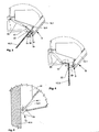
- Fig. 2 the extractor hood according to the invention can be seen in a side view, wherein in the designated "B" area, the housing 6 is shown partially broken.
- the wall-near part 10.2 ranges in the illustrated operating position except for a small gap on the wall surface 12, on which the hood is mounted in its installed position approach.
- a part of the wall surface 12 is covered by the near-wall part 10.2 in this position of the hood.
- a cleaning of this part of the wall surface 12 is made very difficult and without the use of special tools in conventional cooker hoods not possible.
- the distance between the near-wall part 10.2 and the wall surface 12 can not be reduced to zero due to manufacturing reasons and the different mounting conditions on site. The resulting problem is solved by the extractor hood according to the invention.
- Fig. 2 shows, the near-wall part 10.2 by means of a rotary joint 14 is pivotally held on the wall remote part 10.1.
- the hinge 14 is in detail in the Fig. 3 to 5 shown.
- the wall-near part 10.2 is in force-transmitting connection with a gas pressure spring 16, which is held in an articulated manner on the housing 6.
- a gas pressure spring 16 which is held in an articulated manner on the housing 6.
- the near-wall part 10.2 which is designed as a glass, designed as a sheet metal angle lever arm 17 is fixed in a manner known to those skilled in the, based on the 3 and 4 is explained in more detail.
- Fig. 3 shows the detail "B" Fig. 2 in an enlarged view.
- the near-wall part 10.2 abuts against a stop 18 located on the wall-remote part 10.1, the stop 18 contacting the near-wall part 10.2 in such a way that a stop 10 results in a stop being caused by the gas spring 16 on the wall-proximate part 10.2 applied force opposite force is introduced into the near-wall part 10.2.
- the extractor hood according to the invention is still shown with activated transport lock.
- activated transport lock for this purpose, arranged on the wall remote part 10.1 and designed as a sheet metal angle stop 18 on a projection 18.1, in which a in the Fig. 3 invisible longitudinal opening is formed.
- the lever arm 17 engages with a hook formed thereon in the longitudinal opening and locked with the projection 18.1.
- the lever arm 17 is in Fig. 4 shown in detail.
- the transport lock must be solved.
- the projection 18.1 in the direction of the Lever arm 17 bent away side bent until the hook with the projection 18.1 is no longer engaged.
- an intake opening 8 is formed in the transition region of the two parts 10.1 and 10.2 of the inflow element 10, which is in flow communication with the blower, not shown.
- the transition region of the two parts 10.1 and 10.2 of the Anströmelements 10 designed as a flow guide lamp 20 is arranged, which promotes the movement of the flowing along the Anströmelement 10 Wrasens in the direction of the intake 8.
- the lamp 20 is designed as a light bar, the in Fig. 3 is shown in cross section.
- Fig. 4 is the near-wall part 10.2 shown in its rest position.
- the exact shape of the designed as a sheet metal angle lever arm 17 is made Fig. 4 clearly visible.
- the near-wall part 10.2 abuts against a stop 22 in its rest position.
- the stop 22 contacts the wall-proximal part 10.2 in such a way that a force opposing the force exerted by the gas pressure spring 16 on the wall-proximate part 10.2 is introduced into the wall-proximal part 10.2 by the stop 22.
- the Fig. 5 shows the pivot 14 in detail, with the near-wall part 10.2 is in the cleaning position.
- the swivel joint 14 has two bearing bushes 14.1 arranged on the wall-proximal part 10.2 and two bearing bolts 14.2 arranged on the wall-distant part 10.1 and designed as sheet metal tongues, in which Fig. 5 only a bearing bush 14.1 and a bearing pin 14.2 are shown in a side view.
- the bearing pins 14.2 have a substantially rectangular cross section and the bearing bushes 14.1 have a corresponding free cross section, the surface of which is obtainable by a rotation of the respective bearing pin 14.2 by about 40 ° in both directions of rotation about the pivot 14.
- the axis of rotation is in Fig.
- the bearing bushes 14.1 are formed as openings in the wall-near part 10.2 fixed sheet metal bracket 26.
- the sheet metal tongues are formed in a manner known to those skilled in the art from the wall of the housing 6.
- one or more of a bearing bush 14.1 and a bearing pin 14.2 existing pairings for forming the pivot joint 14 are required.
Landscapes
- Engineering & Computer Science (AREA)
- Chemical & Material Sciences (AREA)
- Combustion & Propulsion (AREA)
- Mechanical Engineering (AREA)
- General Engineering & Computer Science (AREA)
- Ventilation (AREA)
Priority Applications (1)
| Application Number | Priority Date | Filing Date | Title |
|---|---|---|---|
| PL05026565T PL1679475T3 (pl) | 2004-12-21 | 2005-12-06 | Okap wyciągu oparów do montażu blisko ściany |
Applications Claiming Priority (1)
| Application Number | Priority Date | Filing Date | Title |
|---|---|---|---|
| DE102004061374A DE102004061374B3 (de) | 2004-12-21 | 2004-12-21 | Dunstabzugshaube zur wandnahen Montage |
Publications (2)
| Publication Number | Publication Date |
|---|---|
| EP1679475A1 EP1679475A1 (de) | 2006-07-12 |
| EP1679475B1 true EP1679475B1 (de) | 2013-11-13 |
Family
ID=35825318
Family Applications (1)
| Application Number | Title | Priority Date | Filing Date |
|---|---|---|---|
| EP05026565.1A Expired - Lifetime EP1679475B1 (de) | 2004-12-21 | 2005-12-06 | Dunstabzugshaube zur wandnahen Montage |
Country Status (3)
| Country | Link |
|---|---|
| EP (1) | EP1679475B1 (pl) |
| DE (1) | DE102004061374B3 (pl) |
| PL (1) | PL1679475T3 (pl) |
Families Citing this family (6)
| Publication number | Priority date | Publication date | Assignee | Title |
|---|---|---|---|---|
| DE102006041582A1 (de) * | 2006-09-05 | 2008-03-06 | BSH Bosch und Siemens Hausgeräte GmbH | Dunstabzugshaube |
| DE102009001187A1 (de) * | 2009-02-26 | 2010-09-02 | BSH Bosch und Siemens Hausgeräte GmbH | Adapter für ein Befestigungsgestell einer Dunstabzugshaube, insbesondere einer Inseldunstabzugshaube |
| CN203323210U (zh) * | 2013-06-24 | 2013-12-04 | 佛山市顺德区合捷电器实业有限公司 | 一种具有面板防夹功能的油烟机 |
| CN109595645B (zh) * | 2017-09-30 | 2024-01-16 | 宁波方太厨具有限公司 | 一种近吸式吸油烟机 |
| DE102018129117A1 (de) * | 2018-11-20 | 2020-05-20 | Miele & Cie. Kg | Solitäre Wanddunstabzugshaube |
| CN116025933B (zh) * | 2021-10-27 | 2025-11-21 | 佛山市顺德区美的洗涤电器制造有限公司 | 油烟机 |
Family Cites Families (4)
| Publication number | Priority date | Publication date | Assignee | Title |
|---|---|---|---|---|
| GB981223A (en) * | 1960-05-10 | 1965-01-20 | Elm Works Ltd | Improvements in and relating to air-purifying appliances |
| US3520115A (en) * | 1968-06-24 | 1970-07-14 | American Air Filter Co | Collapsible hood assembly |
| GB2256703B (en) * | 1991-06-11 | 1995-03-15 | Wu Min Woei | Smoke exhauster |
| DE10039881A1 (de) * | 2000-08-16 | 2002-03-07 | Electrolux Ag Zuerich | Dunstabzugshaube |
-
2004
- 2004-12-21 DE DE102004061374A patent/DE102004061374B3/de not_active Expired - Fee Related
-
2005
- 2005-12-06 PL PL05026565T patent/PL1679475T3/pl unknown
- 2005-12-06 EP EP05026565.1A patent/EP1679475B1/de not_active Expired - Lifetime
Also Published As
| Publication number | Publication date |
|---|---|
| DE102004061374B3 (de) | 2006-03-09 |
| PL1679475T3 (pl) | 2014-03-31 |
| EP1679475A1 (de) | 2006-07-12 |
Similar Documents
| Publication | Publication Date | Title |
|---|---|---|
| DE4102049C2 (pl) | ||
| EP0555757A1 (de) | Fahrzeughaube mit Scharnier | |
| WO2013053347A1 (de) | Betätigungseinrichtung für ein kraftfahrzeug-türschloss | |
| DE102004063178A1 (de) | Scheibenwischvorrichtung | |
| EP0085173A1 (de) | Lüftungseinrichtung | |
| WO2008125252A1 (de) | Scharnieranordnung | |
| DE102012206577B4 (de) | Tür-Schließvorrichtung | |
| EP2094924A2 (de) | Türschloss für türen von luftfahrzeugen, insbesondere von hubschraubern | |
| DE102006027912A1 (de) | Außengriff für Türen von Automobilen | |
| DE4112132A1 (de) | Hebelwerk, insbesondere fusshebelwerk fuer kraftfahrzeuge | |
| DE3405654C2 (de) | Betätigungsvorrichtung für Schalteinrichtungen | |
| DE102004061374B3 (de) | Dunstabzugshaube zur wandnahen Montage | |
| EP1181177A1 (de) | Scheibenwischerantrieb | |
| EP2089660B1 (de) | Dunstabzugshaube | |
| DE2239643C3 (de) | Scheibenwischereinrichtung für Kraftfahrzeuge | |
| EP2230395B1 (de) | Vergaser für einen Verbrennungsmotor | |
| DE102007061672A1 (de) | Dunstabzugsvorrichtung | |
| DE3324162A1 (de) | Griffbeschlag, insbesondere fuer kraftfahrzeugtueren | |
| DE2558313C3 (de) | Schwenkvorrichtung für federkraftunterstützte Hauben oder Klappen | |
| DE102016112187B4 (de) | Scharnier einer Fronthaube eines Kraftfahrzeugs | |
| DE2723643A1 (de) | Verschlussvorrichtung fuer eine abdeckklappe vor einer oeffnung eines haushaltgeraete-gehaeuses | |
| DE4331756C2 (de) | Arretierungseinrichtung für Motorhauben von Kraftfahrzeugen | |
| DE102009013247B4 (de) | Tankklappenverriegelungseinrichtung | |
| DE10347576B3 (de) | Ausstellbare Flaplamelle | |
| DE2936049A1 (de) | Klappe fuer fahrzeuge |
Legal Events
| Date | Code | Title | Description |
|---|---|---|---|
| PUAI | Public reference made under article 153(3) epc to a published international application that has entered the european phase |
Free format text: ORIGINAL CODE: 0009012 |
|
| AK | Designated contracting states |
Kind code of ref document: A1 Designated state(s): AT BE BG CH CY CZ DE DK EE ES FI FR GB GR HU IE IS IT LI LT LU LV MC NL PL PT RO SE SI SK TR |
|
| AX | Request for extension of the european patent |
Extension state: AL BA HR MK YU |
|
| 17P | Request for examination filed |
Effective date: 20061124 |
|
| AKX | Designation fees paid |
Designated state(s): AT BE BG CH CY CZ DE DK EE ES FI FR GB GR HU IE IS IT LI LT LU LV MC NL PL PT RO SE SI SK TR |
|
| GRAP | Despatch of communication of intention to grant a patent |
Free format text: ORIGINAL CODE: EPIDOSNIGR1 |
|
| INTG | Intention to grant announced |
Effective date: 20130702 |
|
| GRAS | Grant fee paid |
Free format text: ORIGINAL CODE: EPIDOSNIGR3 |
|
| GRAA | (expected) grant |
Free format text: ORIGINAL CODE: 0009210 |
|
| AK | Designated contracting states |
Kind code of ref document: B1 Designated state(s): AT BE BG CH CY CZ DK EE ES FI FR GB GR HU IE IS IT LI LT LU LV MC NL PL PT RO SE SI SK TR |
|
| RBV | Designated contracting states (corrected) |
Designated state(s): AT BE BG CH CY CZ DK EE ES FI FR GB GR HU IE IS IT LI LT LU LV MC NL PL PT RO SE SI SK TR |
|
| REG | Reference to a national code |
Ref country code: GB Ref legal event code: FG4D Free format text: NOT ENGLISH Ref country code: DE Ref legal event code: R108 |
|
| REG | Reference to a national code |
Ref country code: CH Ref legal event code: EP |
|
| REG | Reference to a national code |
Ref country code: CH Ref legal event code: NV Representative=s name: FIAMMENGHI-FIAMMENGHI, CH |
|
| REG | Reference to a national code |
Ref country code: AT Ref legal event code: REF Ref document number: 640738 Country of ref document: AT Kind code of ref document: T Effective date: 20131215 |
|
| REG | Reference to a national code |
Ref country code: IE Ref legal event code: FG4D Free format text: LANGUAGE OF EP DOCUMENT: GERMAN |
|
| REG | Reference to a national code |
Ref country code: DE Ref legal event code: R108 Effective date: 20131113 |
|
| REG | Reference to a national code |
Ref country code: NL Ref legal event code: VDEP Effective date: 20131113 |
|
| REG | Reference to a national code |
Ref country code: LT Ref legal event code: MG4D |
|
| PG25 | Lapsed in a contracting state [announced via postgrant information from national office to epo] |
Ref country code: FI Free format text: LAPSE BECAUSE OF FAILURE TO SUBMIT A TRANSLATION OF THE DESCRIPTION OR TO PAY THE FEE WITHIN THE PRESCRIBED TIME-LIMIT Effective date: 20131113 Ref country code: NL Free format text: LAPSE BECAUSE OF FAILURE TO SUBMIT A TRANSLATION OF THE DESCRIPTION OR TO PAY THE FEE WITHIN THE PRESCRIBED TIME-LIMIT Effective date: 20131113 Ref country code: LT Free format text: LAPSE BECAUSE OF FAILURE TO SUBMIT A TRANSLATION OF THE DESCRIPTION OR TO PAY THE FEE WITHIN THE PRESCRIBED TIME-LIMIT Effective date: 20131113 Ref country code: SE Free format text: LAPSE BECAUSE OF FAILURE TO SUBMIT A TRANSLATION OF THE DESCRIPTION OR TO PAY THE FEE WITHIN THE PRESCRIBED TIME-LIMIT Effective date: 20131113 Ref country code: IS Free format text: LAPSE BECAUSE OF FAILURE TO SUBMIT A TRANSLATION OF THE DESCRIPTION OR TO PAY THE FEE WITHIN THE PRESCRIBED TIME-LIMIT Effective date: 20140313 |
|
| PG25 | Lapsed in a contracting state [announced via postgrant information from national office to epo] |
Ref country code: LV Free format text: LAPSE BECAUSE OF FAILURE TO SUBMIT A TRANSLATION OF THE DESCRIPTION OR TO PAY THE FEE WITHIN THE PRESCRIBED TIME-LIMIT Effective date: 20131113 Ref country code: ES Free format text: LAPSE BECAUSE OF FAILURE TO SUBMIT A TRANSLATION OF THE DESCRIPTION OR TO PAY THE FEE WITHIN THE PRESCRIBED TIME-LIMIT Effective date: 20131113 Ref country code: CY Free format text: LAPSE BECAUSE OF FAILURE TO SUBMIT A TRANSLATION OF THE DESCRIPTION OR TO PAY THE FEE WITHIN THE PRESCRIBED TIME-LIMIT Effective date: 20131113 |
|
| BERE | Be: lapsed |
Owner name: MIELE & CIE. K.G. Effective date: 20131231 |
|
| PG25 | Lapsed in a contracting state [announced via postgrant information from national office to epo] |
Ref country code: PT Free format text: LAPSE BECAUSE OF FAILURE TO SUBMIT A TRANSLATION OF THE DESCRIPTION OR TO PAY THE FEE WITHIN THE PRESCRIBED TIME-LIMIT Effective date: 20140313 |
|
| PG25 | Lapsed in a contracting state [announced via postgrant information from national office to epo] |
Ref country code: EE Free format text: LAPSE BECAUSE OF FAILURE TO SUBMIT A TRANSLATION OF THE DESCRIPTION OR TO PAY THE FEE WITHIN THE PRESCRIBED TIME-LIMIT Effective date: 20131113 |
|
| PG25 | Lapsed in a contracting state [announced via postgrant information from national office to epo] |
Ref country code: RO Free format text: LAPSE BECAUSE OF FAILURE TO SUBMIT A TRANSLATION OF THE DESCRIPTION OR TO PAY THE FEE WITHIN THE PRESCRIBED TIME-LIMIT Effective date: 20131113 Ref country code: SK Free format text: LAPSE BECAUSE OF FAILURE TO SUBMIT A TRANSLATION OF THE DESCRIPTION OR TO PAY THE FEE WITHIN THE PRESCRIBED TIME-LIMIT Effective date: 20131113 Ref country code: CZ Free format text: LAPSE BECAUSE OF FAILURE TO SUBMIT A TRANSLATION OF THE DESCRIPTION OR TO PAY THE FEE WITHIN THE PRESCRIBED TIME-LIMIT Effective date: 20131113 Ref country code: MC Free format text: LAPSE BECAUSE OF FAILURE TO SUBMIT A TRANSLATION OF THE DESCRIPTION OR TO PAY THE FEE WITHIN THE PRESCRIBED TIME-LIMIT Effective date: 20131113 |
|
| PLBE | No opposition filed within time limit |
Free format text: ORIGINAL CODE: 0009261 |
|
| STAA | Information on the status of an ep patent application or granted ep patent |
Free format text: STATUS: NO OPPOSITION FILED WITHIN TIME LIMIT |
|
| REG | Reference to a national code |
Ref country code: IE Ref legal event code: MM4A |
|
| REG | Reference to a national code |
Ref country code: FR Ref legal event code: ST Effective date: 20140829 |
|
| PG25 | Lapsed in a contracting state [announced via postgrant information from national office to epo] |
Ref country code: DK Free format text: LAPSE BECAUSE OF FAILURE TO SUBMIT A TRANSLATION OF THE DESCRIPTION OR TO PAY THE FEE WITHIN THE PRESCRIBED TIME-LIMIT Effective date: 20131113 |
|
| 26N | No opposition filed |
Effective date: 20140814 |
|
| GBPC | Gb: european patent ceased through non-payment of renewal fee |
Effective date: 20140213 |
|
| PG25 | Lapsed in a contracting state [announced via postgrant information from national office to epo] |
Ref country code: IE Free format text: LAPSE BECAUSE OF NON-PAYMENT OF DUE FEES Effective date: 20131206 Ref country code: BE Free format text: LAPSE BECAUSE OF NON-PAYMENT OF DUE FEES Effective date: 20131231 |
|
| PG25 | Lapsed in a contracting state [announced via postgrant information from national office to epo] |
Ref country code: FR Free format text: LAPSE BECAUSE OF NON-PAYMENT OF DUE FEES Effective date: 20140113 |
|
| PG25 | Lapsed in a contracting state [announced via postgrant information from national office to epo] |
Ref country code: GB Free format text: LAPSE BECAUSE OF NON-PAYMENT OF DUE FEES Effective date: 20140213 |
|
| PG25 | Lapsed in a contracting state [announced via postgrant information from national office to epo] |
Ref country code: SI Free format text: LAPSE BECAUSE OF FAILURE TO SUBMIT A TRANSLATION OF THE DESCRIPTION OR TO PAY THE FEE WITHIN THE PRESCRIBED TIME-LIMIT Effective date: 20131113 |
|
| PG25 | Lapsed in a contracting state [announced via postgrant information from national office to epo] |
Ref country code: BG Free format text: LAPSE BECAUSE OF FAILURE TO SUBMIT A TRANSLATION OF THE DESCRIPTION OR TO PAY THE FEE WITHIN THE PRESCRIBED TIME-LIMIT Effective date: 20131113 Ref country code: LU Free format text: LAPSE BECAUSE OF NON-PAYMENT OF DUE FEES Effective date: 20131206 Ref country code: HU Free format text: LAPSE BECAUSE OF FAILURE TO SUBMIT A TRANSLATION OF THE DESCRIPTION OR TO PAY THE FEE WITHIN THE PRESCRIBED TIME-LIMIT; INVALID AB INITIO Effective date: 20051206 |
|
| PG25 | Lapsed in a contracting state [announced via postgrant information from national office to epo] |
Ref country code: GR Free format text: LAPSE BECAUSE OF NON-PAYMENT OF DUE FEES Effective date: 20131113 |
|
| PG25 | Lapsed in a contracting state [announced via postgrant information from national office to epo] |
Ref country code: GR Free format text: LAPSE BECAUSE OF FAILURE TO SUBMIT A TRANSLATION OF THE DESCRIPTION OR TO PAY THE FEE WITHIN THE PRESCRIBED TIME-LIMIT Effective date: 20140214 |
|
| PGFP | Annual fee paid to national office [announced via postgrant information from national office to epo] |
Ref country code: TR Payment date: 20171204 Year of fee payment: 13 |
|
| PGFP | Annual fee paid to national office [announced via postgrant information from national office to epo] |
Ref country code: CH Payment date: 20171221 Year of fee payment: 13 Ref country code: PL Payment date: 20171205 Year of fee payment: 13 Ref country code: AT Payment date: 20171228 Year of fee payment: 13 |
|
| PGFP | Annual fee paid to national office [announced via postgrant information from national office to epo] |
Ref country code: IT Payment date: 20171220 Year of fee payment: 13 |
|
| REG | Reference to a national code |
Ref country code: CH Ref legal event code: PL |
|
| REG | Reference to a national code |
Ref country code: AT Ref legal event code: MM01 Ref document number: 640738 Country of ref document: AT Kind code of ref document: T Effective date: 20181206 |
|
| PG25 | Lapsed in a contracting state [announced via postgrant information from national office to epo] |
Ref country code: IT Free format text: LAPSE BECAUSE OF NON-PAYMENT OF DUE FEES Effective date: 20181206 |
|
| PG25 | Lapsed in a contracting state [announced via postgrant information from national office to epo] |
Ref country code: CH Free format text: LAPSE BECAUSE OF NON-PAYMENT OF DUE FEES Effective date: 20181231 Ref country code: AT Free format text: LAPSE BECAUSE OF NON-PAYMENT OF DUE FEES Effective date: 20181206 Ref country code: LI Free format text: LAPSE BECAUSE OF NON-PAYMENT OF DUE FEES Effective date: 20181231 |
|
| PG25 | Lapsed in a contracting state [announced via postgrant information from national office to epo] |
Ref country code: PL Free format text: LAPSE BECAUSE OF NON-PAYMENT OF DUE FEES Effective date: 20181206 |
|
| PG25 | Lapsed in a contracting state [announced via postgrant information from national office to epo] |
Ref country code: TR Free format text: LAPSE BECAUSE OF NON-PAYMENT OF DUE FEES Effective date: 20181206 |