EP1674207B1 - Power tool - Google Patents
Power tool Download PDFInfo
- Publication number
- EP1674207B1 EP1674207B1 EP05023196A EP05023196A EP1674207B1 EP 1674207 B1 EP1674207 B1 EP 1674207B1 EP 05023196 A EP05023196 A EP 05023196A EP 05023196 A EP05023196 A EP 05023196A EP 1674207 B1 EP1674207 B1 EP 1674207B1
- Authority
- EP
- European Patent Office
- Prior art keywords
- drive sleeve
- gear
- drive shaft
- teeth
- claw portion
- Prior art date
- Legal status (The legal status is an assumption and is not a legal conclusion. Google has not performed a legal analysis and makes no representation as to the accuracy of the status listed.)
- Not-in-force
Links
Images


Classifications
-
- B—PERFORMING OPERATIONS; TRANSPORTING
- B25—HAND TOOLS; PORTABLE POWER-DRIVEN TOOLS; MANIPULATORS
- B25D—PERCUSSIVE TOOLS
- B25D16/00—Portable percussive machines with superimposed rotation, the rotational movement of the output shaft of a motor being modified to generate axial impacts on the tool bit
- B25D16/006—Mode changers; Mechanisms connected thereto
-
- B—PERFORMING OPERATIONS; TRANSPORTING
- B25—HAND TOOLS; PORTABLE POWER-DRIVEN TOOLS; MANIPULATORS
- B25D—PERCUSSIVE TOOLS
- B25D2211/00—Details of portable percussive tools with electromotor or other motor drive
- B25D2211/003—Crossed drill and motor spindles
-
- B—PERFORMING OPERATIONS; TRANSPORTING
- B25—HAND TOOLS; PORTABLE POWER-DRIVEN TOOLS; MANIPULATORS
- B25D—PERCUSSIVE TOOLS
- B25D2216/00—Details of portable percussive machines with superimposed rotation, the rotational movement of the output shaft of a motor being modified to generate axial impacts on the tool bit
- B25D2216/0007—Details of percussion or rotation modes
- B25D2216/0015—Tools having a percussion-only mode
-
- B—PERFORMING OPERATIONS; TRANSPORTING
- B25—HAND TOOLS; PORTABLE POWER-DRIVEN TOOLS; MANIPULATORS
- B25D—PERCUSSIVE TOOLS
- B25D2216/00—Details of portable percussive machines with superimposed rotation, the rotational movement of the output shaft of a motor being modified to generate axial impacts on the tool bit
- B25D2216/0007—Details of percussion or rotation modes
- B25D2216/0023—Tools having a percussion-and-rotation mode
-
- B—PERFORMING OPERATIONS; TRANSPORTING
- B25—HAND TOOLS; PORTABLE POWER-DRIVEN TOOLS; MANIPULATORS
- B25D—PERCUSSIVE TOOLS
- B25D2216/00—Details of portable percussive machines with superimposed rotation, the rotational movement of the output shaft of a motor being modified to generate axial impacts on the tool bit
- B25D2216/0007—Details of percussion or rotation modes
- B25D2216/0038—Tools having a rotation-only mode
Definitions
- the present invention relates to a power tool.
- the invention relates particularly, but not exclusively, to a mode change mechanism for selecting a hammering mode, a rotary mode, and a combined hammering and rotary mode, and to a power tool incorporating such a mode change mechanism.
- Hammer drills are power tools which can operate in one of three modes of operation.
- a hammer drill will have a tool bit which can be operated in a hammering mode, a rotary mode and a combined hammering and rotary mode.
- Hammer drills also generally comprise a mode change mechanism which enables a user to select between the different modes of operation of the hammer drill.
- European patent application EP0759342 discloses a hammer drill having a mode change mechanism comprising an axially slidable lock ring which is disposed on the spindle of the hammer drill.
- the rotational mode of the hammer drill is selected by rotating an eccentric pin which moves the lock ring in the axial direction along the spindle in order to couple or decouple the lock ring from a tool holder to selectively cause rotation of the tool holder.
- United States patent US5456324 discloses a hammer drill having a rotatable drive cylinder containing a hollow piston, the drive cylinder adapted to hold a tool bit such that the tool bit can be used in both a rotary mode and a reciprocating mode.
- a drive wheel is rotatably mounted on the drive cylinder, the drive wheel being geared to the motor of the tool.
- a coupling sleeve is key coupled to the drive cylinder so that the coupling sleeve can slide axially along the drive cylinder and also rotate with the drive cylinder. Both the coupling sleeve and the drive wheel have sets of teeth formed thereon such that they can intermesh.
- United States patent US5379848 comprises a hammer drill having a rotary drive sleeve comprising a tool holder, and an axially displaceable switching sleeve that can slide along the spindle in order to selectively couple the rotary drive sleeve to the rotational drive of a motor.
- the switching sleeve is biased into an operative position by a coil spring, and is moved by an eccentrically mounted pin.
- United States patent US5125461 discloses a hammer drill having a stop element which in a first position permits axial displacement for the activation of the hammer mechanism, and a second position in which the stop element blocks the axial displacement, thus preventing the hammering action of the hammer drill.
- United States patent US6557648 discloses a hammer drill having a motor with a output drive shaft, a housing accommodating the motor therein, and a mode change mechanism comprising a first gear with a claw portion and engaged with the output shaft for transmitting rotation of the output shaft, and a second gear having a claw portion and engaged with the output shaft for transmitting rotation of the output shaft.
- the mode change mechanism comprises a first drive sleeve having a claw portion enageable with the claw portion of the first gear for transmitting rotation of the output shaft when the claw portion of the first drive sleeve is engaged with the claw portion of the first gear, a crank shaft driven in response to the rotation of the first drive sleeve, and a hammer mechanism responsive to the rotation of the reciprocating drive shaft for transmitting a reciprocating striking force to a tool bit.
- the mode change mechanism comprises a second drive sleeve having a claw portion enageable with the claw portion of the second gear for transmitting rotation of the output shaft when the claw portion of the second drive sleeve is engaged with the claw portion of the second gear, a rotary drive shaft driven in response to the rotation of the second drive sleeve, and a rotary mechanism responsive to rotation of the rotary drive shaft for transmitting a rotational force to the tool bit.
- the mode change mechanism further comprises a switching mechanism for selectively engaging or disengaging the claw portion of the first drive sleeve with or from the claw portion of the first gear and also selectively engaging or disengaging the claw portion of the second drive sleeve with or from the claw portion of the second gear.
- the switching mechanism includes a rotatable switching lever with two eccentric pins. One pin is for moving the first drive sleeve upwards and the other pin is for moving a shift member upwards so as to engage with, and move upwards, the second drive sleeve.
- the shift member is slideably mounted on a switch assist shaft substantially parallel to the crank shaft and rotary shaft.
- a spring biases the shift member downwards. This is in addition to the springs that bias the first and second drive sleeves downwards so that their claw portions engage the claw portions of the first and second gears, respectively. Therefore, the switching mechanism is a relatively complex system involving several moving parts which make it expensive to manufacture and assemble.
- Preferred embodiments of the present invention seek to overcome the above disadvantages of the prior art.
- a hammer drill having a motor with a output shaft, a housing accommodating the motor therein, and a mode change mechanism comprising a first gear with a claw portion and engaged with the output shaft for transmitting rotation of the output shaft, a second gear having a claw portion and engaged with the output shaft for transmitting rotation of the output shaft, a first drive sleeve having a claw portion engageable with the claw portion of the first gear for transmitting rotation of the output shaft when the claw portion of the first sleeve is engaged with the claw portion of the first gear, a reciprocating drive shaft driven in response to the rotation of the first drive sleeve, a hammer mechanism responsive to the rotation of the crank shaft for transmitting a reciprocating striking force to a tool bit, a second drive sleeve having a claw portion engageable with the claw portion of the second gear for transmitting rotation of the output shaft when the claw portion of the second sleeve is engaged with the claw portion of the second gear,
- the seesaw lever simplifies the switching mechanism because it is one single component that can control the position of the first and second drive sleeves simultaneously.
- the mode change mechanism further comprises a first biasing means adapted to bias the claw portions of the first drive sleeve and the first gear into engagement and a second biasing means adapted to bias the claw portions of the second drive sleeve and the second gear into engagement.
- the claw portions are normally in engagement and the engaging portions of the seesaw lever need only abut the drive sleeves in a direction opposing to the bias of these biasing means in order to control the position of the drive sleeves.
- the first and second drive sleeves have the shape of a hat with a flange protruding radially.
- This has the advantage that the engaging portions of the seesaw lever need only abut the underside of the flanges of the drive sleeves which is a simple construction. It has the further advantage that the engaging portions can be shaped to neatly surround the drive sleeves by abutting the majority of the underside of the flanges thereby providing more solid support for the drive sleeves.
- the switching mechanism further comprises a control plate rotatably connected to the housing, a control finger connected to the control plate and protruding outwardly therefrom towards the seesaw lever wherein the control finger protrudes through at least one elongate slot in the seesaw lever, wherein the control finger is located eccentrically in relation to the rotational axis of the control plate and the elongate slot is located eccentrically in relation to the pivotal axis of the seesaw lever so that rotation of the control plate results in pivotal movement of the seesaw lever from one side to the other.
- This has the advantage that control plate has positive control of the seesaw lever because the control finger is always captive inside the elongate slot.
- the recprocating drive shaft has a plurality of longitudinal outer splines formed thereon and the first drive sleeve surrounding the recprocating drive shaft and has a plurality of longitudinal inner splines formed on its interior surface wherein the inner and outer splines slidably mesh so that the first drive sleeve can slide up and down the recprocating drive shaft but the first drive sleeve cannot rotate relative to the recprocating drive shaft.
- the rotary drive shaft has a plurality of longitudinal outer splines formed thereon and the second drive sleeve surrounding the rotary drive shaft and has a plurality of longitudinal inner splines formed on its interior surface wherein the inner and outer splines slidably mesh so that the second drive sleeve can slide up and down the rotary drive shaft but the second drive sleeve cannot rotate relative to the rotary drive shaft.
- the outer and the inner splines are parallel to the axis of the reciprocating or rotary drive shafts.
- the outer and the inner splines of the second drive sleeve and the second drive shaft, respectively, are inclined to the axis of the rotary drive shaft.
- these inner and the outer splines are "helical splines”.
- the helical splines arrangement provides a simple and compact torque overload clutch within the mode change mechanism.
- the claw portions of the first gear and the first drive sleeve comprise a circular array of primary drive sleeve teeth formed upon one end of the first drive sleeve and a corresponding circular array of gear teeth formed upon a facing surface of the first gear whereby the primary drive sleeve teeth are engageable with the gear teeth for transmitting rotation of the first gear to the reciprocating drive shaft.
- the claw portions of the second gear and the second drive sleeve comprise a circular array of primary drive sleeve teeth formed upon one end of the second drive sleeve and a corresponding circular array of gear teeth formed upon a facing surface of the second gear whereby the primary drive sleeve teeth are engageable with the gear teeth for transmitting rotation of the second gear to the rotary drive shaft.
- a circular array of secondary drive sleeve teeth is formed upon an opposite end of the second drive sleeve and a corresponding array of housing teeth is formed upon a portion of the housing facing the secondary drive sleeve teeth, whereby the secondary drive sleeve teeth are engageable with the housing teeth for locking the rotary drive shaft against free rotation when the mode change mechanism has selected hammering only mode.
- a circular array of secondary drive sleeve teeth is formed upon an opposite end of the first drive sleeve and a corresponding array of housing teeth is formed upon a portion of the housing facing the secondary drive sleeve teeth, whereby the secondary drive sleeve teeth are engageable with the housing teeth for locking the reciprocating drive shaft against free rotation when the mode change mechanism has selected rotary only mode.
- the rotary mechanism comprises a first bevel gear connected to the top end of the rotary drive shaft and a second bevel gear connected to a main spindle of the hammer drill, whereby the first bevel gear meshes with the second bevel gear to transmit rotation of the rotary drive shaft to the main spindle.
- the hammering mechanism comprises a crank plate having a crank pin disposed eccentrically thereon connected to the top end of the reciprocating drive shaft and a hollow piston having a ram disposed slidably therein mounted to the housing, whereby a crank arm is pivotally connected to the crank pin and the hollow piston so that rotation of the crank plate causes reciprocation of the hollow piston which in turn causes reciprocation of the ram relative to the hollow piston.
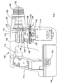
- a hammer drill shown generally by 102 comprises a housing 104 formed from at least two clamshell halves of durable plastics material, as will be understood by persons skilled in the art. Extending from a forward end of housing 104 is a chuck 106 or similar device for gripping a drill bit (not shown). A rechargeable battery pack 108 is detachably fixed to the bottom of the housing, and can be detached from the housing 104 by depressing clips 110 to release the battery pack for the purpose of recharging or exchange.
- the housing 104 comprises a handle portion 112 having a trigger switch 114.
- An electric motor 116 is disposed in the housing. The motor is electrically coupled to the battery pack via the trigger switch.
- the trigger switch is for selectively energising the motor to operate the hammer drill.
- An output shaft 118 extends from the motor 116.
- the output shaft 118 has a pinion 120 formed thereon.
- the pinion 120 meshes with a first gear 122 and a second gear 124.
- the output shaft 118 and pinion 120 rotate.
- the pinion drives the first gear 122 and the second gear 124 simultaneously.
- the first gear 122 is mounted upon and freely rotatable about the lower end of a first drive shaft 126.
- the second gear 124 is mounted upon and freely rotatable about the lower end of a second drive shaft 128.
- the first drive shaft is mounted within the housing for rotation about its axis 129.
- the second drive shaft is mounted within the housing for rotation about its axis 131.
- the first and second drive shaft axes 129, 131 are parallel to each other.
- the pinion 120 can mesh with one of the first gear 122 or the second gear 124 which, in turn, meshes with the other of the first gear 122 or the second gear 124. This is a simple way of reversing the rotation of the first and second gears 122, 124 relative to each other, if required.
- a crank plate 138 is connected to the top end of the first drive shaft 126.
- the crank plate has a crank pin 140 protruding upwards.
- the crank pin is located eccentrically in relation to the axis of the first drive shaft and the crank plate.
- the crank pin is pivotally coupled to a crank arm 142 which is pivotally coupled to a hollow piston 144 with a cylindrical internal cavity.
- a cylindrical ram (not shown) is disposed within the cylindrical cavity of the hollow piston.
- the rectilinear reciprocating motion of the hollow piston causes the ram member to reciprocate under an air spring effect of the air contained by the walls the ram and the cylindrical cavity of the hollow piston.
- the reciprocating ram member repeatedly strikes the rear end of a drill bit (not shown) held in the chuck 106 which provides the hammering mode operation of the hammer drill.
- This type of mechanism will be well known to persons skilled in the art, and will not be described in any more detail.
- a first bevel gear 132 is connected to the top end of the second drive shaft 128.
- the first bevel gear 132 rotates with the second drive shaft 128.
- a second bevel gear 134 is connected to a main spindle 136.
- the second bevel gear rotates with the main spindle.
- the main spindle, the hollow piston and the ram all have the same axis 152.
- the main spindle 136 is mounted in the housing for rotation about the axis 152.
- the first bevel gear 132 meshes with the second bevel gear 134 so that rotation of first bevel gear is transmitted to the main spindle via the second bevel gear. This provides the rotary mode operation of the hammer drill.
- This type of mechanism will also be well known to persons skilled in the art and will not be described in any more detail herein.
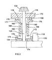
- the second drive shaft 128 has a plurality of longitudinal outer splines 160 formed thereon.
- a second drive sleeve 162 surrounds second drive shaft 128 and has a plurality of longitudinal inner splines 166 formed on its interior surface.
- the outer and the inner splines 160, 162 are parallel to the axis 131 of the second drive shaft 128.
- the inner splines 166 slidably mesh with outer splines 160 such that the second drive sleeve 162 can slide up and down the second drive shaft but it cannot rotate relative to the second drive shaft.
- a coil spring 168 is fixed at one end to a portion 170 of the housing 104.
- the other end of the coil spring 168 slidably engages an upper surface of a flange 171 of the second drive sleeve 162. As a result, the coil spring 168 biases second drive sleeve 162 downward. However, the second drive sleeve 162 can still rotate without restriction from the coil spring 168.
- a circular array of primary drive sleeve teeth 172 is formed upon a bottom edge of the second drive sleeve 162.
- a corresponding circular array of gear plate teeth 174 is formed upon a top surface of the second gear 124.
- the primary drive sleeve teeth mesh with the gear plate teeth when the second drive sleeve 162 is moved into its lowermost position under the influence of the coil spring 168. Rotation of the second gear 124 is thus transmitted to the second drive shaft 128 via the meshed inner and outer splines 160, 166.
- a circular array of secondary drive sleeve teeth 176 is formed upon the top surface of the flange 171.
- a corresponding array of housing teeth 176 is formed upon the bottom of the housing portion 170.
- the secondary drive sleeve teeth mesh with the housing teeth when the second drive sleeve 162 is moved into its uppermost position against the influence of the coil spring 168.
- the second drive sleeve 162 is thus locked and the meshed inner and outer splines 160, 166 prevent free rotation of the second drive shaft 128 when the mode change mechanism has selected hammering only mode.
- the teeth 176 are replaced by a detent mounted on the housing portion 170 which can engage with recesses in the second drive sleeve 162 when the latter is moved into its uppermost position.
- the first drive shaft 126 is provided with a first drive sleeve 164 and the two components operate in exactly the same way as the second drive sleeve 162 on the second drive shaft 128.
- the first drive sleeve is a replica of the second drive sleeve.
- the first drive sleeve has a flange 173 corresponding to the flange 171 of the second drive sleeve, as is shown in Figures 3 to 5 .
- the first drive shaft is almost a replica of the second drive shaft, the only difference being that the crank plate 138 is connected to the top end of the first drive shaft (instead of the first bevel gear 132), as is mentioned above.
- the inner and outer splines 160, 166 of the second drive shaft and drive sleeve 128, 162 are inclined to the axis 131 of the second drive sleeve i.e. the inner and the outer splines 160, 166 are "helical splines".
- the inner and the outer splines 160, 166 are "helical splines”.
- the point at which the main spindle 136 is disconnected from the drive shaft 118 of the motor 116 is influenced by the spring co-efficient of the coil spring 168 and/or the angle of inclination of the inner and outer splines 160, 166 to the axis 131.
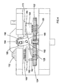
- a switching mechanism for the mode change mechanism has a seesaw lever 180 comprising a C-shaped first bracket 184 on one side and a C-shaped second bracket 182 on the other side.
- the first and second brackets are arranged with their open ends facing in opposite directions.
- the first bracket surrounds a portion of the first drive sleeve 164 and is arranged to abut the underside of its flange 173.
- the second bracket surrounds a portion of the second drive sleeve 162 and is arranged to abut the underside of its flange 171.
- the seesaw lever 180 further comprises pair of pivot plates 186 located between the first and second brackets and extending perpendicularly therefrom.
- Each pivot plate 186 comprises a circular aperture 188 through which a cylindrical pin 192 passes.
- the pin is fixed to the housing 104.
- the pin 192 is the pivotal axis of seesaw lever 180.
- Each pivot plate 186 further comprises an elongate slot 190 through which a control finger 194 passes.
- the elongate slot is generally parallel to the axes 129,131 of the first and second drive shafts 126, 128, although it can rock from side to side when the seesaw lever pivots about the pin 192, as is described in below.
- a cylindrical control plate 196 is rotatably fixed to the housing 104.
- the control finger 194 is connected to the control plate and protrudes outwardly from the control plate towards the seesaw lever.
- the control finger is located eccentrically in relation to the axis of the control plate.
- a user can rotate the control plate 196 through 360° causing the control finger to rotate therewith.
- the control finger's rotational movement has a component parallel to the axes 129,131 of the first and second drive shafts 126, 128 (the vertical component) and a component perpendicular to said axes (the horizontal component).
- the vertical component is accommodated by the control finger sliding along the elongate slot 190 because the elongate slot is generally vertical.
- the control plate can be operated to change the seesaw lever from a position tilting towards the first drive shaft 126, as shown in Figure 3 ; to a position generally perpendicular to the axes 129,131 of the first and second drive shafts 126, 128, as shown in Figure 5 ; and a position tilting towards the second drive shaft 128, as shown in Figure 4 .
- the seesaw lever is tilted towards the first drive shaft so that the first bracket 184 is in its lowermost position and does not abut the flange 173.
- the first drive sleeve 164 is moved downwards under the influence of coil spring 169 so that the first drive shaft 126 is engaged with the first gear 122 via the first drive sleeve 164.
- rotation of the first gear 122 results in rotation of the crank pin 140 and activation of the hammering mode of the hammer drill.
- the second bracket 182 is moved into its uppermost position and abuts the flange 171.
- the second drive sleeve 162 is moved upwards by the second bracket 182 against the influence of the coil spring 169 so that the second drive shaft 128 is disengaged from the second gear 124. Instead, the secondary drive sleeve teeth 176 mesh with the housing teeth 178. This prevents the second drive shaft 128 from rotating and prevents the first bevel gear 132 from driving the rotary mode of the hammer drill.
- the control plate 196 has been rotated 90° anti-clockwise from the position shown in Figure 3 so that the seesaw lever 180 is moved to a position generally perpendicular to the axes 129,131 of the first and second drive shafts 126, 128.
- the first and second brackets 182, 184 are moved into their middle position and each bracket gently abuts a respective flange 171,173.
- the second drive sleeve 162 is moved downwards under the influence of the coil spring 169 so that the second drive shaft 128 is engaged with the first gear 124.
- the first drive sleeve 164 remains in the position shown in Figure 3 so that the first drive shaft 126 remains engaged with the first gear 122.
- rotation of the second gear 124 rotates of the first bevel gear 132 and the rotation of the first gear 122 rotates the crank pin 140 to drive the combined rotary and hammering mode of the hammer drill.
- the control plate 196 has been rotated 90° anti-clockwise from the position shown in Figure 5 so that the seesaw lever is tilted towards the second drive shaft 128.
- the second bracket 182 is in its lowermost position and does not abut the flange 171.
- the second drive sleeve 162 is moved downwards under the influence of coil spring 169 so that the second drive shaft 128 is engaged with the second gear 124 via the second drive sleeve 162.
- rotation of the second gear 124 results in rotation of the first bevel gear 132 and activation of the rotary mode of the hammer drill.
- the first bracket 184 is moved into its uppermost position and abuts the flange 173.
- the first drive sleeve 164 is moved upwards by the first bracket 184 against the influence of the coil spring 169 so that the first drive shaft 126 is disengaged from the first gear 124. Instead, the secondary drive sleeve teeth 176 mesh with the housing teeth 178. This prevents the first drive shaft 126 from rotating and prevents the crank pin 140 from driving the hammering mode of the hammer drill.
- one of the first bracket 184 or the second bracket 182 can be deleted from the seesaw lever 180 so that the mode change mechanism can operate in two modes only. If the first bracket 184 is deleted then the first drive sleeve 164 and the first gear 122 remain permanently engaged so that hammering mode cannot be de-selected by the user i.e. rotary only mode is unavailable. Conversely, if the second bracket 182 is deleted then the second drive sleeve 162 and the second gear 124 remain permanently engaged so that rotary mode cannot be de-selected by the user i.e. hammering only mode is unavailable.
- This design option may be adopted without altering other aspects of the mode change mechanism, as described above. This design option may be attractive in countries where usage conditions mean that one of the modes is rarely used and the reduction in weight and cost caused by this modification makes it viable.
Landscapes
- Engineering & Computer Science (AREA)
- Mechanical Engineering (AREA)
- Percussive Tools And Related Accessories (AREA)
Applications Claiming Priority (2)
| Application Number | Priority Date | Filing Date | Title |
|---|---|---|---|
| GBGB0428210.9A GB0428210D0 (en) | 2004-12-23 | 2004-12-23 | Mode change mechanism |
| GB0510935A GB2421463A (en) | 2004-12-23 | 2005-05-27 | Hammer drill with a switching mechanism including a seesaw lever |
Publications (2)
| Publication Number | Publication Date |
|---|---|
| EP1674207A1 EP1674207A1 (en) | 2006-06-28 |
| EP1674207B1 true EP1674207B1 (en) | 2008-12-10 |
Family
ID=36046894
Family Applications (1)
| Application Number | Title | Priority Date | Filing Date |
|---|---|---|---|
| EP05023196A Not-in-force EP1674207B1 (en) | 2004-12-23 | 2005-10-25 | Power tool |
Country Status (4)
| Country | Link |
|---|---|
| US (1) | US7306049B2 (ja) |
| EP (1) | EP1674207B1 (ja) |
| JP (1) | JP4828926B2 (ja) |
| AU (1) | AU2005230182A1 (ja) |
Families Citing this family (40)
| Publication number | Priority date | Publication date | Assignee | Title |
|---|---|---|---|---|
| DE102005056205A1 (de) * | 2005-11-25 | 2007-06-06 | Robert Bosch Gmbh | Bohrhammer mit drei Betriebsarten |
| US7469752B2 (en) * | 2005-12-02 | 2008-12-30 | Makita Corporation | Power tool |
| US7594548B1 (en) * | 2006-07-26 | 2009-09-29 | Black & Decker Inc. | Power tool having a joystick control |
| DE102006054288A1 (de) * | 2006-11-17 | 2008-05-21 | A & M Electric Tools Gmbh | Bohrhammer |
| DE102006059076A1 (de) * | 2006-12-14 | 2008-06-19 | Robert Bosch Gmbh | Schlagwerk einer Elektrohandwerkzeugmaschine |
| JP4976170B2 (ja) * | 2007-03-09 | 2012-07-18 | 株式会社マキタ | 打撃工具 |
| JP4981506B2 (ja) * | 2007-04-12 | 2012-07-25 | 株式会社マキタ | ハンマードリル |
| US7806198B2 (en) | 2007-06-15 | 2010-10-05 | Black & Decker Inc. | Hybrid impact tool |
| US7484714B1 (en) * | 2007-10-26 | 2009-02-03 | Chizong Machine Co., Ltd. | Chargeable electric winch |
| US8631777B2 (en) * | 2008-02-08 | 2014-01-21 | Bluskies International Llc | Rigid primer bulb pump |
| EP2147753B1 (de) * | 2008-07-25 | 2017-01-18 | AEG Electric Tools GmbH | Elektrowerkzeug mit Getriebeumschaltung |
| US9193053B2 (en) | 2008-09-25 | 2015-11-24 | Black & Decker Inc. | Hybrid impact tool |
| JP5416397B2 (ja) | 2008-12-19 | 2014-02-12 | 株式会社マキタ | 作業工具 |
| DE102009005248A1 (de) | 2009-01-13 | 2010-07-15 | C. & E. Fein Gmbh | Elektrowerkzeug mit schaltbarem Getriebe |
| US8631880B2 (en) * | 2009-04-30 | 2014-01-21 | Black & Decker Inc. | Power tool with impact mechanism |
| JP5396149B2 (ja) * | 2009-05-20 | 2014-01-22 | 株式会社マキタ | 動力工具 |
| JP5479023B2 (ja) | 2009-10-20 | 2014-04-23 | 株式会社マキタ | 充電式電動工具 |
| JP5496605B2 (ja) * | 2009-11-02 | 2014-05-21 | 株式会社マキタ | 打撃工具 |
| BR112012011424B1 (pt) | 2009-11-13 | 2020-10-20 | Intuitive Surgical Operations, Inc | instrumento cirúrgico |
| US9259275B2 (en) * | 2009-11-13 | 2016-02-16 | Intuitive Surgical Operations, Inc. | Wrist articulation by linked tension members |
| EP2489323B1 (en) | 2009-11-13 | 2018-05-16 | Intuitive Surgical Operations, Inc. | Surgical tool with a compact wrist |
| KR101800723B1 (ko) | 2009-11-13 | 2017-11-23 | 인튜어티브 서지컬 오퍼레이션즈 인코포레이티드 | 독립적으로 회전하는 부재 내의 병렬 구동 샤프트들을 위한 모터 연접부 |
| US8460153B2 (en) | 2009-12-23 | 2013-06-11 | Black & Decker Inc. | Hybrid impact tool with two-speed transmission |
| DE102010004961A1 (de) | 2010-01-20 | 2011-07-21 | AEG Electric Tools GmbH, 71364 | Elektrowerkzeug |
| US8584770B2 (en) | 2010-03-23 | 2013-11-19 | Black & Decker Inc. | Spindle bearing arrangement for a power tool |
| CN102371573A (zh) * | 2010-08-10 | 2012-03-14 | 南京德朔实业有限公司 | 电动工具 |
| CN102476222B (zh) * | 2010-11-24 | 2014-12-10 | 南京德朔实业有限公司 | 用于振荡工具上的开孔器 |
| JP5770549B2 (ja) | 2011-07-01 | 2015-08-26 | 株式会社マキタ | 打撃工具 |
| US9630307B2 (en) * | 2012-08-22 | 2017-04-25 | Milwaukee Electric Tool Corporation | Rotary hammer |
| EP2821183B1 (en) * | 2013-07-05 | 2017-06-21 | Black & Decker Inc. | Hammer Drill |
| GB201321893D0 (en) | 2013-12-11 | 2014-01-22 | Black & Decker Inc | Rotary Hammer |
| CA3146951A1 (en) | 2014-03-27 | 2015-10-01 | Techtronic Power Tools Technology Limited | Powered fastener driver and operating method thereof |
| DE102015206634A1 (de) * | 2015-04-14 | 2016-10-20 | Robert Bosch Gmbh | Werkzeugvorsatz für eine Handwerkzeugmaschine |
| GB2545237A (en) | 2015-12-10 | 2017-06-14 | Black & Decker Inc | Planetray gear system |
| JP2018015881A (ja) * | 2016-07-29 | 2018-02-01 | パナソニックIpマネジメント株式会社 | 電動工具 |
| EP4219082A1 (en) | 2017-07-31 | 2023-08-02 | Milwaukee Electric Tool Corporation | Rotary power tool |
| US10994399B2 (en) | 2017-07-31 | 2021-05-04 | Ryan Duggan | Hammer drill and set tool device |
| WO2022159471A1 (en) * | 2021-01-19 | 2022-07-28 | Milwaukee Electric Tool Corporation | Rotary power tool |
| JP2022188999A (ja) * | 2021-06-10 | 2022-12-22 | 株式会社マキタ | 回転打撃工具 |
| JP2022188996A (ja) * | 2021-06-10 | 2022-12-22 | 株式会社マキタ | 回転打撃工具 |
Family Cites Families (42)
| Publication number | Priority date | Publication date | Assignee | Title |
|---|---|---|---|---|
| GB1229290A (ja) | 1968-08-16 | 1971-04-21 | ||
| DE2242944B2 (de) * | 1972-08-31 | 1981-04-23 | Robert Bosch Gmbh, 7000 Stuttgart | Bohrhammer |
| US4020935A (en) | 1975-07-01 | 1977-05-03 | Facet Enterprises, Inc. | Direct cranking starter drive |
| JPS54120504A (en) * | 1978-03-10 | 1979-09-19 | Nippon Telegr & Teleph Corp <Ntt> | On-off control system for power supply |
| DE3311265A1 (de) | 1983-03-28 | 1984-10-11 | Hilti Ag, Schaan | Elektropneumatischer bohr- und meisselhammer |
| US4627299A (en) | 1984-12-20 | 1986-12-09 | Facet Enterprises, Inc. | Engine starter gearing |
| DE3504650C2 (de) | 1985-02-12 | 1994-01-20 | Bosch Gmbh Robert | Bohrhammer mit Verstärkung der Betätigungskraft für die Kupplung des Schlagantriebes |
| DE3506695A1 (de) | 1985-02-26 | 1986-08-28 | Robert Bosch Gmbh, 7000 Stuttgart | Bohrhammer |
| DE3538166A1 (de) | 1985-10-26 | 1987-04-30 | Hilti Ag | Bohrhammer mit dreharretierung |
| DE3841515A1 (de) | 1988-12-09 | 1990-06-13 | Hilti Ag | Handwerkzeug mit schaltgetriebe |
| CH681353A5 (ja) * | 1989-05-17 | 1993-03-15 | Aluweld Sa | |
| GB2232372A (en) | 1989-05-25 | 1990-12-12 | Black & Decker Inc | Improvements in or relating to power tools |
| DE3931329C1 (ja) | 1989-05-31 | 1990-06-28 | Robert Bosch Gmbh, 7000 Stuttgart, De | |
| DE4010037A1 (de) | 1990-03-29 | 1991-10-02 | Hilti Ag | Bohrgeraet mit schaltgetriebe |
| DE4013512A1 (de) | 1990-04-27 | 1991-10-31 | Black & Decker Inc | Schalteinrichtung zum umschalten eines kraftgetriebenen werkzeugs |
| DE4215288A1 (de) | 1991-07-08 | 1993-01-14 | Bosch Gmbh Robert | Bohrhammer |
| DE4135240A1 (de) | 1991-10-25 | 1993-04-29 | Bosch Gmbh Robert | Bohrhammer |
| USD349101S (en) | 1992-01-13 | 1994-07-26 | BACO Constructions Electriques - Anct. Baumgarten S.A. | Electrical switch actuator |
| US5320177A (en) | 1992-03-30 | 1994-06-14 | Makita Corporation | Power driven hammer drill |
| DE4231986A1 (de) | 1992-09-24 | 1994-03-31 | Bosch Gmbh Robert | Bohr- und/oder Schlaghammer |
| JP2602411Y2 (ja) | 1993-11-26 | 2000-01-17 | 日立工機株式会社 | 打撃工具の切換機構 |
| KR0114561Y1 (ko) | 1994-01-19 | 1998-04-17 | 배순훈 | 비디오 카세트 레코더용 회전스위치장치 |
| JP3424880B2 (ja) | 1995-08-18 | 2003-07-07 | 株式会社マキタ | ハンマードリル |
| USD395586S (en) | 1996-02-20 | 1998-06-30 | Makita Corporation | Portable electric hammer |
| DE19717712A1 (de) * | 1997-04-18 | 1998-10-22 | Black & Decker Inc | Bohrhammer |
| JP3582760B2 (ja) | 1997-04-18 | 2004-10-27 | 日立工機株式会社 | ハンマドリル |
| JP3609626B2 (ja) * | 1998-09-16 | 2005-01-12 | 株式会社マキタ | ハンマードリル |
| US6142242A (en) | 1999-02-15 | 2000-11-07 | Makita Corporation | Percussion driver drill, and a changeover mechanism for changing over a plurality of operating modes of an apparatus |
| US6223833B1 (en) | 1999-06-03 | 2001-05-01 | One World Technologies, Inc. | Spindle lock and chipping mechanism for hammer drill |
| JP3688943B2 (ja) | 1999-08-26 | 2005-08-31 | 株式会社マキタ | ハンマードリル |
| DE10029728A1 (de) | 2000-06-16 | 2001-12-20 | Hilti Ag | Handwerkzeuggerät |
| DE10031050A1 (de) | 2000-06-26 | 2002-01-10 | Hilti Ag | Handwerkzeuggerät |
| DE10033100A1 (de) | 2000-07-07 | 2002-01-17 | Hilti Ag | Kombiniertes Elektrohandwerkzeuggerät |
| DE10151699B4 (de) | 2000-10-20 | 2005-06-30 | Hitachi Koki Co., Ltd. | Bohrhammer |
| JP4281273B2 (ja) * | 2000-10-20 | 2009-06-17 | 日立工機株式会社 | ハンマドリル |
| GB0100605D0 (en) | 2001-01-10 | 2001-02-21 | Black & Decker Inc | Hammer |
| DE10108124A1 (de) | 2001-02-21 | 2002-08-29 | Hilti Ag | Modenwahldrehschalter für ein Handwerkzeuggerät |
| DE10111748A1 (de) | 2001-03-12 | 2002-09-19 | Hilti Ag | Schaltwerk für ein kombiniertes Handwerkzeuggerät |
| DE10111746A1 (de) | 2001-03-12 | 2002-09-19 | Hilti Ag | Schaltübertragungsmittel zur kombinierten Schaltung eines Getriebes |
| US6665923B2 (en) | 2001-06-29 | 2003-12-23 | Porter-Cable/Delta | Clutch for a screw gun and utilizing method |
| GB2419170B (en) * | 2002-09-13 | 2006-12-06 | Black & Decker Inc | Rotary tool having overload clutch with three modes of operation |
| JP3976187B2 (ja) | 2002-11-20 | 2007-09-12 | 株式会社マキタ | ハンマードリル |
-
2005
- 2005-10-25 EP EP05023196A patent/EP1674207B1/en not_active Not-in-force
- 2005-11-08 AU AU2005230182A patent/AU2005230182A1/en not_active Abandoned
- 2005-12-15 JP JP2005361816A patent/JP4828926B2/ja not_active Expired - Fee Related
- 2005-12-21 US US11/314,559 patent/US7306049B2/en not_active Expired - Fee Related
Also Published As
| Publication number | Publication date |
|---|---|
| AU2005230182A1 (en) | 2006-07-13 |
| JP4828926B2 (ja) | 2011-11-30 |
| US20060137888A1 (en) | 2006-06-29 |
| EP1674207A1 (en) | 2006-06-28 |
| JP2006175594A (ja) | 2006-07-06 |
| US7306049B2 (en) | 2007-12-11 |
Similar Documents
| Publication | Publication Date | Title |
|---|---|---|
| EP1674207B1 (en) | Power tool | |
| GB2421463A (en) | Hammer drill with a switching mechanism including a seesaw lever | |
| EP1477280B1 (en) | Rotary hammer | |
| EP2062697B1 (en) | A hammer-drill with mode collar | |
| EP2062670B1 (en) | Multi-mode Drill with an Electronic Switching Arrangement | |
| EP1987925B1 (en) | Hammer drill | |
| EP2062693B1 (en) | Hammer drill with hard hammer support structure | |
| EP2062696B1 (en) | Multi-mode hammer drill with shift lock | |
| EP1832393B1 (en) | Power tool | |
| JP2001062621A (ja) | ハンマードリル | |
| WO2007058149A1 (ja) | ハンマドリル | |
| EP2883660B1 (en) | Rotary hammer | |
| US20100270045A1 (en) | Handheld power tool | |
| US10399216B2 (en) | Rotary hammer | |
| CN215545159U (zh) | 锂电冲击钻 | |
| CN113183098B (zh) | 冲击钻 |
Legal Events
| Date | Code | Title | Description |
|---|---|---|---|
| PUAI | Public reference made under article 153(3) epc to a published international application that has entered the european phase |
Free format text: ORIGINAL CODE: 0009012 |
|
| AK | Designated contracting states |
Kind code of ref document: A1 Designated state(s): AT BE BG CH CY CZ DE DK EE ES FI FR GB GR HU IE IS IT LI LT LU LV MC NL PL PT RO SE SI SK TR |
|
| AX | Request for extension of the european patent |
Extension state: AL BA HR MK YU |
|
| 17P | Request for examination filed |
Effective date: 20060706 |
|
| 17Q | First examination report despatched |
Effective date: 20060811 |
|
| AKX | Designation fees paid |
Designated state(s): AT BE BG CH CY CZ DE DK EE ES FI FR GB GR HU IE IS IT LI LT LU LV MC NL PL PT RO SE SI SK TR |
|
| GRAP | Despatch of communication of intention to grant a patent |
Free format text: ORIGINAL CODE: EPIDOSNIGR1 |
|
| GRAS | Grant fee paid |
Free format text: ORIGINAL CODE: EPIDOSNIGR3 |
|
| GRAS | Grant fee paid |
Free format text: ORIGINAL CODE: EPIDOSNIGR3 |
|
| GRAA | (expected) grant |
Free format text: ORIGINAL CODE: 0009210 |
|
| AK | Designated contracting states |
Kind code of ref document: B1 Designated state(s): AT BE BG CH CY CZ DE DK EE ES FI FR GB GR HU IE IS IT LI LT LU LV MC NL PL PT RO SE SI SK TR |
|
| REG | Reference to a national code |
Ref country code: GB Ref legal event code: FG4D |
|
| REG | Reference to a national code |
Ref country code: CH Ref legal event code: EP |
|
| REG | Reference to a national code |
Ref country code: IE Ref legal event code: FG4D |
|
| REF | Corresponds to: |
Ref document number: 602005011562 Country of ref document: DE Date of ref document: 20090122 Kind code of ref document: P |
|
| PG25 | Lapsed in a contracting state [announced via postgrant information from national office to epo] |
Ref country code: LT Free format text: LAPSE BECAUSE OF FAILURE TO SUBMIT A TRANSLATION OF THE DESCRIPTION OR TO PAY THE FEE WITHIN THE PRESCRIBED TIME-LIMIT Effective date: 20081210 |
|
| PG25 | Lapsed in a contracting state [announced via postgrant information from national office to epo] |
Ref country code: FI Free format text: LAPSE BECAUSE OF FAILURE TO SUBMIT A TRANSLATION OF THE DESCRIPTION OR TO PAY THE FEE WITHIN THE PRESCRIBED TIME-LIMIT Effective date: 20081210 Ref country code: LV Free format text: LAPSE BECAUSE OF FAILURE TO SUBMIT A TRANSLATION OF THE DESCRIPTION OR TO PAY THE FEE WITHIN THE PRESCRIBED TIME-LIMIT Effective date: 20081210 Ref country code: PL Free format text: LAPSE BECAUSE OF FAILURE TO SUBMIT A TRANSLATION OF THE DESCRIPTION OR TO PAY THE FEE WITHIN THE PRESCRIBED TIME-LIMIT Effective date: 20081210 Ref country code: NL Free format text: LAPSE BECAUSE OF FAILURE TO SUBMIT A TRANSLATION OF THE DESCRIPTION OR TO PAY THE FEE WITHIN THE PRESCRIBED TIME-LIMIT Effective date: 20081210 Ref country code: SI Free format text: LAPSE BECAUSE OF FAILURE TO SUBMIT A TRANSLATION OF THE DESCRIPTION OR TO PAY THE FEE WITHIN THE PRESCRIBED TIME-LIMIT Effective date: 20081210 |
|
| NLV1 | Nl: lapsed or annulled due to failure to fulfill the requirements of art. 29p and 29m of the patents act | ||
| PG25 | Lapsed in a contracting state [announced via postgrant information from national office to epo] |
Ref country code: EE Free format text: LAPSE BECAUSE OF FAILURE TO SUBMIT A TRANSLATION OF THE DESCRIPTION OR TO PAY THE FEE WITHIN THE PRESCRIBED TIME-LIMIT Effective date: 20081210 Ref country code: BG Free format text: LAPSE BECAUSE OF FAILURE TO SUBMIT A TRANSLATION OF THE DESCRIPTION OR TO PAY THE FEE WITHIN THE PRESCRIBED TIME-LIMIT Effective date: 20090310 Ref country code: BE Free format text: LAPSE BECAUSE OF FAILURE TO SUBMIT A TRANSLATION OF THE DESCRIPTION OR TO PAY THE FEE WITHIN THE PRESCRIBED TIME-LIMIT Effective date: 20081210 Ref country code: ES Free format text: LAPSE BECAUSE OF FAILURE TO SUBMIT A TRANSLATION OF THE DESCRIPTION OR TO PAY THE FEE WITHIN THE PRESCRIBED TIME-LIMIT Effective date: 20090321 Ref country code: RO Free format text: LAPSE BECAUSE OF FAILURE TO SUBMIT A TRANSLATION OF THE DESCRIPTION OR TO PAY THE FEE WITHIN THE PRESCRIBED TIME-LIMIT Effective date: 20081210 |
|
| PG25 | Lapsed in a contracting state [announced via postgrant information from national office to epo] |
Ref country code: SE Free format text: LAPSE BECAUSE OF FAILURE TO SUBMIT A TRANSLATION OF THE DESCRIPTION OR TO PAY THE FEE WITHIN THE PRESCRIBED TIME-LIMIT Effective date: 20090310 Ref country code: PT Free format text: LAPSE BECAUSE OF FAILURE TO SUBMIT A TRANSLATION OF THE DESCRIPTION OR TO PAY THE FEE WITHIN THE PRESCRIBED TIME-LIMIT Effective date: 20090511 Ref country code: IS Free format text: LAPSE BECAUSE OF FAILURE TO SUBMIT A TRANSLATION OF THE DESCRIPTION OR TO PAY THE FEE WITHIN THE PRESCRIBED TIME-LIMIT Effective date: 20090410 Ref country code: CZ Free format text: LAPSE BECAUSE OF FAILURE TO SUBMIT A TRANSLATION OF THE DESCRIPTION OR TO PAY THE FEE WITHIN THE PRESCRIBED TIME-LIMIT Effective date: 20081210 Ref country code: AT Free format text: LAPSE BECAUSE OF FAILURE TO SUBMIT A TRANSLATION OF THE DESCRIPTION OR TO PAY THE FEE WITHIN THE PRESCRIBED TIME-LIMIT Effective date: 20081210 |
|
| PG25 | Lapsed in a contracting state [announced via postgrant information from national office to epo] |
Ref country code: SK Free format text: LAPSE BECAUSE OF FAILURE TO SUBMIT A TRANSLATION OF THE DESCRIPTION OR TO PAY THE FEE WITHIN THE PRESCRIBED TIME-LIMIT Effective date: 20081210 |
|
| PLBE | No opposition filed within time limit |
Free format text: ORIGINAL CODE: 0009261 |
|
| STAA | Information on the status of an ep patent application or granted ep patent |
Free format text: STATUS: NO OPPOSITION FILED WITHIN TIME LIMIT |
|
| PG25 | Lapsed in a contracting state [announced via postgrant information from national office to epo] |
Ref country code: DK Free format text: LAPSE BECAUSE OF FAILURE TO SUBMIT A TRANSLATION OF THE DESCRIPTION OR TO PAY THE FEE WITHIN THE PRESCRIBED TIME-LIMIT Effective date: 20081210 |
|
| 26N | No opposition filed |
Effective date: 20090911 |
|
| PG25 | Lapsed in a contracting state [announced via postgrant information from national office to epo] |
Ref country code: MC Free format text: LAPSE BECAUSE OF NON-PAYMENT OF DUE FEES Effective date: 20091031 |
|
| REG | Reference to a national code |
Ref country code: CH Ref legal event code: PL |
|
| REG | Reference to a national code |
Ref country code: FR Ref legal event code: ST Effective date: 20100630 |
|
| PG25 | Lapsed in a contracting state [announced via postgrant information from national office to epo] |
Ref country code: FR Free format text: LAPSE BECAUSE OF NON-PAYMENT OF DUE FEES Effective date: 20091102 |
|
| PG25 | Lapsed in a contracting state [announced via postgrant information from national office to epo] |
Ref country code: CH Free format text: LAPSE BECAUSE OF NON-PAYMENT OF DUE FEES Effective date: 20091031 Ref country code: LI Free format text: LAPSE BECAUSE OF NON-PAYMENT OF DUE FEES Effective date: 20091031 Ref country code: IE Free format text: LAPSE BECAUSE OF NON-PAYMENT OF DUE FEES Effective date: 20091025 Ref country code: GR Free format text: LAPSE BECAUSE OF FAILURE TO SUBMIT A TRANSLATION OF THE DESCRIPTION OR TO PAY THE FEE WITHIN THE PRESCRIBED TIME-LIMIT Effective date: 20090311 |
|
| PG25 | Lapsed in a contracting state [announced via postgrant information from national office to epo] |
Ref country code: IT Free format text: LAPSE BECAUSE OF FAILURE TO SUBMIT A TRANSLATION OF THE DESCRIPTION OR TO PAY THE FEE WITHIN THE PRESCRIBED TIME-LIMIT Effective date: 20081210 |
|
| PG25 | Lapsed in a contracting state [announced via postgrant information from national office to epo] |
Ref country code: LU Free format text: LAPSE BECAUSE OF NON-PAYMENT OF DUE FEES Effective date: 20091025 |
|
| PG25 | Lapsed in a contracting state [announced via postgrant information from national office to epo] |
Ref country code: HU Free format text: LAPSE BECAUSE OF FAILURE TO SUBMIT A TRANSLATION OF THE DESCRIPTION OR TO PAY THE FEE WITHIN THE PRESCRIBED TIME-LIMIT Effective date: 20090611 |
|
| PG25 | Lapsed in a contracting state [announced via postgrant information from national office to epo] |
Ref country code: TR Free format text: LAPSE BECAUSE OF FAILURE TO SUBMIT A TRANSLATION OF THE DESCRIPTION OR TO PAY THE FEE WITHIN THE PRESCRIBED TIME-LIMIT Effective date: 20081210 |
|
| PG25 | Lapsed in a contracting state [announced via postgrant information from national office to epo] |
Ref country code: CY Free format text: LAPSE BECAUSE OF FAILURE TO SUBMIT A TRANSLATION OF THE DESCRIPTION OR TO PAY THE FEE WITHIN THE PRESCRIBED TIME-LIMIT Effective date: 20081210 |
|
| PGFP | Annual fee paid to national office [announced via postgrant information from national office to epo] |
Ref country code: DE Payment date: 20181009 Year of fee payment: 14 |
|
| PGFP | Annual fee paid to national office [announced via postgrant information from national office to epo] |
Ref country code: GB Payment date: 20181024 Year of fee payment: 14 |
|
| REG | Reference to a national code |
Ref country code: DE Ref legal event code: R119 Ref document number: 602005011562 Country of ref document: DE |
|
| PG25 | Lapsed in a contracting state [announced via postgrant information from national office to epo] |
Ref country code: DE Free format text: LAPSE BECAUSE OF NON-PAYMENT OF DUE FEES Effective date: 20200501 |
|
| GBPC | Gb: european patent ceased through non-payment of renewal fee |
Effective date: 20191025 |
|
| PG25 | Lapsed in a contracting state [announced via postgrant information from national office to epo] |
Ref country code: GB Free format text: LAPSE BECAUSE OF NON-PAYMENT OF DUE FEES Effective date: 20191025 |