EP2147753B1 - Elektrowerkzeug mit Getriebeumschaltung - Google Patents
Elektrowerkzeug mit Getriebeumschaltung Download PDFInfo
- Publication number
- EP2147753B1 EP2147753B1 EP08161170.9A EP08161170A EP2147753B1 EP 2147753 B1 EP2147753 B1 EP 2147753B1 EP 08161170 A EP08161170 A EP 08161170A EP 2147753 B1 EP2147753 B1 EP 2147753B1
- Authority
- EP
- European Patent Office
- Prior art keywords
- power tool
- drive shaft
- actuating element
- sleeves
- coupling sleeve
- Prior art date
- Legal status (The legal status is an assumption and is not a legal conclusion. Google has not performed a legal analysis and makes no representation as to the accuracy of the status listed.)
- Active
Links
Images


Classifications
-
- B—PERFORMING OPERATIONS; TRANSPORTING
- B25—HAND TOOLS; PORTABLE POWER-DRIVEN TOOLS; MANIPULATORS
- B25D—PERCUSSIVE TOOLS
- B25D16/00—Portable percussive machines with superimposed rotation, the rotational movement of the output shaft of a motor being modified to generate axial impacts on the tool bit
- B25D16/006—Mode changers; Mechanisms connected thereto
-
- B—PERFORMING OPERATIONS; TRANSPORTING
- B25—HAND TOOLS; PORTABLE POWER-DRIVEN TOOLS; MANIPULATORS
- B25D—PERCUSSIVE TOOLS
- B25D2211/00—Details of portable percussive tools with electromotor or other motor drive
- B25D2211/06—Means for driving the impulse member
- B25D2211/061—Swash-plate actuated impulse-driving mechanisms
-
- B—PERFORMING OPERATIONS; TRANSPORTING
- B25—HAND TOOLS; PORTABLE POWER-DRIVEN TOOLS; MANIPULATORS
- B25D—PERCUSSIVE TOOLS
- B25D2216/00—Details of portable percussive machines with superimposed rotation, the rotational movement of the output shaft of a motor being modified to generate axial impacts on the tool bit
- B25D2216/0007—Details of percussion or rotation modes
- B25D2216/0015—Tools having a percussion-only mode
-
- B—PERFORMING OPERATIONS; TRANSPORTING
- B25—HAND TOOLS; PORTABLE POWER-DRIVEN TOOLS; MANIPULATORS
- B25D—PERCUSSIVE TOOLS
- B25D2216/00—Details of portable percussive machines with superimposed rotation, the rotational movement of the output shaft of a motor being modified to generate axial impacts on the tool bit
- B25D2216/0007—Details of percussion or rotation modes
- B25D2216/0023—Tools having a percussion-and-rotation mode
-
- B—PERFORMING OPERATIONS; TRANSPORTING
- B25—HAND TOOLS; PORTABLE POWER-DRIVEN TOOLS; MANIPULATORS
- B25D—PERCUSSIVE TOOLS
- B25D2216/00—Details of portable percussive machines with superimposed rotation, the rotational movement of the output shaft of a motor being modified to generate axial impacts on the tool bit
- B25D2216/0007—Details of percussion or rotation modes
- B25D2216/0038—Tools having a rotation-only mode
-
- B—PERFORMING OPERATIONS; TRANSPORTING
- B25—HAND TOOLS; PORTABLE POWER-DRIVEN TOOLS; MANIPULATORS
- B25D—PERCUSSIVE TOOLS
- B25D2216/00—Details of portable percussive machines with superimposed rotation, the rotational movement of the output shaft of a motor being modified to generate axial impacts on the tool bit
- B25D2216/0007—Details of percussion or rotation modes
- B25D2216/0046—Preventing rotation
Definitions
- the invention relates to a power tool, in particular a drill and chisel hammer, with a drive shaft and two output elements, wherein the drive shaft is operatively connected to the output elements via a coupling sleeve.
- the coupling sleeves are actuated by a rotatable, mechanical actuator, in particular a mechanical rotary switch.
- Power tools such as rotary and chisel hammers, in which a movement of a drive shaft is transmitted to two output elements, usually have a coupling device which allows engagement and disengagement for a power transmission between the drive shaft and the output elements.
- the output elements should not be coupled to the drive shaft in every operating state of the power tool. In this case, it is therefore necessary that the power flow between the drive shaft and the corresponding output element can be interrupted.
- rotary switches are often used by which a user can select two or three operating states of the power tool. Since the coupling elements are usually actuated by a translational movement, in this case, a deflection mechanism is required, which transmits the rotational movement of the rotary switch in a translational movement of the coupling elements.
- a corresponding deflection mechanism is usually formed by a slide switch, which is movable by corresponding guide rails along the operating direction of the coupling elements.
- said slide switch is often based on a complicated mechanism which translates the rotational movement of the rotary switch into corresponding translational movements and directions of the respective coupling elements.
- a disadvantage of such an embodiment of a power tool is that the slide switch is formed by a complex component.
- the additional component also requires a certain amount of space in the housing and complicates the production of the power tool.
- a power tool namely a rotary hammer known which has a drive shaft and two output elements, wherein the drive shaft with the output elements is operatively connected via a coupling sleeve, wherein the coupling sleeves are actuated by a rotatable mechanical actuator in the form of a mechanical rotary switch, wherein the actuating element a stationary relative to the actuating element transmission device, which is directly engageable with one of the coupling sleeves for the actuation of one of the coupling sleeve in contact.
- the object of the present invention is to construct a power tool with the features of the preamble of claim 1, which has a straightforward clutch actuating mechanism.
- the actuating element comprises a stationary relative to the actuating element transmission device, which is directly engageable with the respective coupling sleeve for actuating one of the coupling sleeves in contact.
- the transmission device is thus a fixedly mounted on the actuator element, which acts directly, ie without additional deflection or guide mechanisms on the coupling sleeves.
- a transmission device in which a transmission device is provided, which has the above features, can be dispensed with a complex construction of a slide switch or similar components. By eliminating such a component, the entire power tool can be made simpler and the housing can be made leaner.
- the power tool is more reliable in the direct transmission of the operation of the gear change to the coupling sleeves compared to a power tool with a slide switch.
- the actuating element it is further possible to perform the actuator as a mechanical rotary switch, so that the operability of the power tool is maintained compared to conventional power tools.
- an output element can be locked by a locking device of the power tool against rotation. If the corresponding output element is disengaged by the actuating element from the movement of the drive shaft, it may be undesirable that the disengaged output element can move freely about its axis of rotation. In order to counteract such a movement, the locking device is provided, which can lock the driven element against rotational movements.
- the locking device is used in the above-mentioned case in which the output element is disengaged from the movement of the drive shaft. It is also conceivable, however, that the drive shaft is also lockable when the driven element is engaged with the locking device by said locking device. This can be provided, for example, to secure a parked power tool.
- the designed as a locking plate locking device according to the invention is spring-loaded in the direction of the coupling sleeves.
- the configured as a rotary switch actuator is set to only allow a locking of the respective output element when the associated coupling sleeve is disengaged.
- the actuating element may have a flat stop surface, by which the locking device is movable in the direction of the coupling sleeves, wherein the locking device is otherwise supported against a cylinder jacket-shaped part of the actuating element.
- the coupling sleeves are mounted axially displaceably on the drive shaft.
- the coupling sleeves which are mounted axially displaceably on the drive shaft, on the one hand a simple power transmission by direct coupling between the coupling sleeve and the drive shaft, on the other hand, this coupling can also be easily interrupted by axial displacement on the drive shaft.
- the coupling mechanism between the drive shaft and the respective output element through the coupling sleeve is therefore particularly easy to implement in a correspondingly mounted coupling sleeve.
- the output elements are mounted on the drive shaft freewheeling, so that the drive shaft to move independently and surrounded by the output elements can.
- it is also particularly uncomplicated to produce the power flow between the coupling sleeves and the output elements, if the coupling sleeves are mounted on the drive shaft.
- the coupling sleeves are designed for producing a form-locking operative connection between the drive shaft and the output elements.
- a particularly safe and low-wear power transmission between the drive shaft and the respective output element is ensured.
- the coupling sleeves produce a frictional connection between the drive shaft and the respective output element.
- the power flow extends from the drive shaft to the coupling sleeve as well as from the coupling sleeve to the respective output element by positive engagement. This power transmission is particularly wear.
- the coupling sleeves in the direction of a first position, in which the drive shaft and the respective output element are operatively connected to each other, preferably acted upon by a spring force, wherein the respective first positions are preferably axially opposite set.
- a spring force acts on each of the coupling sleeves and pushes them in the direction of the engaged position, in which the drive shaft is coupled to the respective output element. This means that by applying the actuating element and via the transmission device, a force counteracting the application of force is to be applied to the respective coupling sleeve to be actuated.
- a disengagement of the coupling sleeve is effected, which otherwise always remains engaged by the application.
- a single spring element can be used to act on both coupling sleeves, which extends between the coupling sleeves.
- each of the coupling sleeves is supported via the spring element against the respective other coupling sleeve. This therefore leads to a further simplification of the housing, since no separate stop for the spring element must be present.
- the coupling sleeves via the transmission means by the actuating element in each case a second position in which the drive shaft and the respective output element are not operatively connected can be brought.
- the coupling sleeves can thus be brought by the actuating element in each case a position, so that the coupling sleeve interrupts the power flow between the drive shaft and the respective output element.
- This second position, in which the corresponding output element is thus disengaged can be particularly preferably assumed by a displacement of a first coupling sleeve in the direction of the second coupling sleeve.
- the transmission device is selectively brought into contact with one of the coupling sleeves directly.
- This can be made possible, for example, by a single transfer device directly contacting the first coupling sleeve in a first position and being in direct contact with the second coupling sleeve in a second position.
- the transmission device can for example produce a sliding contact with the respective coupling sleeve.
- the coupling sleeve can be displaced in a first direction through the transmission device and can be movable relative to the transmission device in a second, non-parallel, first direction.
- the coupling sleeve relative to the Transmission device rotates.
- the fact that the transmission device is in direct contact with the coupling sleeve can already be fulfilled, for example, by a direct contact of the transmission device with the respective coupling sleeve.
- the transmission device is formed by at least one projection, preferably two projections, wherein the projection preferably extends parallel to the axis of rotation of the actuating element.
- a projection is a particularly simple embodiment of a transmission device, wherein the projection is advantageously extended over a circular arc of an angular range of at least 45 ° on the rotary mechanical actuator or, in the preferred case of two projections, a first projection on a first angular portion of the actuating element and a second projection on a second angle portion of the actuating element, wherein the second angle portion is at an angular distance of at least 45 ° to the first angle portion attached.
- the transmission device is formed by two projections
- one of the two projections in each case with a respective coupling sleeve can be brought into contact and thus the distance by which the mechanical actuating element rotates for contacting a respective coupling sleeve, shortened.
- the projection extends parallel to the axis of rotation of the actuating element, so that it is moved on actuation of the actuating element in constant alignment about the axis of rotation of the actuating element.
- the projection is formed by a pin, which is particularly preferably formed integrally with the actuating element.
- a pin in the actuator represents a particularly simple embodiment of a corresponding projection, but alternatively also an elongated circular arc portion as a continuous Projection can be provided. In the embodiment of the projection by a pin, however, this can be particularly easily connected to the actuator.
- a separate pin for example made of metal, can be particularly preferably inserted into a corresponding actuating element, for example pressed into the actuating element, screwed or otherwise fitted.
- a one-piece design of the projection with the actuating element there is the advantage that the number of parts to be used can be reduced and the production costs and the associated costs can be further reduced. It should be noted, however, that due to the high frictional force between the projection and the coupling sleeve, a heat-resistant design of the two components is important in order to avoid rapid wear of these elements.
- the actuator for selecting three different coupling states between the drive shaft and the two output elements is formed.
- the three different clutch states may be that, on the one hand, the first output element is driven solely by the drive shaft, and the second output element is driven solely by the drive shaft and, moreover, that both output elements are simultaneously driven by the drive shaft.
- the actuating element is used for selecting only two different coupling states.
- the axis of rotation of the actuating element extends substantially parallel to a radial axis of the drive shaft.
- a particularly space-saving and efficient combination of the actuating element with the transmission device and the coupling sleeves to be contacted is possible.
- the The axis of rotation of the actuating element is not exactly on a radial axis of the drive shaft, but is displaced parallel to this.
- the accuracy of the parallelism between the axis of rotation of the actuating element and the respective radial axis of the drive shaft can be in a range of ⁇ 10 °.
- the projection extends parallel to the axis of rotation of the actuating element
- the projection further extends in one of the contact positions with one of the coupling sleeves substantially along an axis extending radially to the drive shaft.
- the projection of the actuating element lies in one of the contact positions, that is to say on an axis extending radially to the drive shaft.
- the accuracy of the orientation of the projection with respect to the axis extending radially to the drive shaft may also be in the range of ⁇ 10 °, wherein the position of the projection with respect to the axis extending radially to the drive shaft with an accuracy of two diameters of the projection on both sides of the axle is to be observed.
- the output elements are a countershaft gear and a wobble drive.
- the actuating element preferably switches between a first state in which the power tool performs a rotational movement of the countershaft gear, a second state in which the power tool performs a movement of the wobble drive, wherein the countershaft gear is rotationally fixed, and a third state in which the power tool a simultaneous movement of the countershaft gear and the Taumeltriebs performs to.
- the countershaft gearwheel it is not necessary in this case for the countershaft gearwheel to be rotationally fixed. It may also be freely rotating in the second state. However, it is preferred that the countershaft gear be rotationally fixed in this state.
- the mechanical actuator in the power tool according to the invention is in contrast to an electronic actuator.
- an electronic actuating device moves a mechanical actuating element which has the properties according to the invention.
- the actuating element is actuated directly, ie directly manually, by a user.
- the actuation of the coupling sleeves by the mechanical actuator means that the clutches are disengaged each actuation. In the non-actuated state, the clutches each ensure a flow of power from the drive shaft to the respective output element; this power flow is interrupted only when actuated.
- the characteristic of the transmission device that it is stationary relative to the actuating element as stated above, means in particular that the transmission device is mounted on the actuating element.
- a pin connected to the actuating element is mentioned, although other elements may also be suitable as a transmission device.
- the central feature of the transmission device that it directly, ie directly, for the actuation of a coupling sleeve, can be brought into contact with the respective coupling sleeve, means that between the stationary located on the actuator transmission and the respective coupling sleeve no linkage, deflection or similar intermediate elements such For example, guides, etc. are located.
- the transmission device rather comes in direct contact with the respective coupling sleeve.
- the transmission device can be selectively brought into direct contact with one of the coupling sleeves means that the transmission device can be brought into contact with the first, the second or neither of the two coupling sleeves.
- the transmission device contacts the respective coupling sleeve in the case of actuation and dissolves completely from it when the coupling sleeve has to establish the frictional connection between the drive shaft and the respective output element.
- the transmission device is made of a temperature-resistant material because of the occurrence of high temperatures due to the possibly high frictional heat between a coupling sleeve and the transmission device.
- a metal or a heat-resistant plastic is used. The latter is to be used in particular in the preferred embodiment of the projection as a transmission device formed integrally with the actuating element.
- the coupling sleeves advantageously have a surface with which the Transmission device of the actuating element can come into contact.
- This attack surface is preferably directly contacted by a housing-side direction of the power tool.
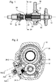
- Fig. 1 shows a gear shift of a preferred embodiment of a power tool according to the present invention in a side view sectional view.
- a Taumeltriebnabe 16 On a horizontally extending drive shaft 12, a Taumeltriebnabe 16, a countershaft gear 14, a first coupling sleeve 18 and a second coupling sleeve 20 is mounted freewheeling.
- the two coupling sleeves 18, 20 are thereby pressed apart and into engagement with the countershaft gearwheel 14 or the wobble drive hub 16 by a helical spring 28, which is mounted in a free-running manner between the two coupling sleeves 18, 20 on the drive shaft 12.
- the spring 28 acts on the coupling sleeves 18, 20 so in opposite directions. Unlike the countershaft gear 14 and the Taumeltriebnabe 16, the coupling sleeves 18, 20 are positively connected to the drive shaft 12 via a gear contour 30, 32 of the drive shaft 12. A rotation of the drive shaft 12 thus leads directly to a rotation of the two coupling sleeves 18, 20th Fig. 1 shows a state in which the coupling sleeves 18, 20 also in each case with the countershaft gear 14 and the Taumeltechnischnabe 16 are positively engaged.
- the journal 34 of the wobble drive which is in a linear guide, is moved back and forth and causes a striking movement in a drill spindle 44 (FIG. Fig. 3 . 5 . 7 ) clamped tool.
- the countershaft gear 14 is rotationally coupled to the drill spindle 44 of the power tool 10 so that rotation of the drive shaft 12, which is transmitted to the countershaft gear 14 via the coupling sleeve 18, results in rotation of the drill spindle 44.
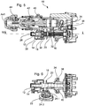
- Fig. 2 shows a further sectional view of the power tool 10 according to the preferred embodiment Fig. 1 ,
- the section is made perpendicular to the drive shaft 12 in the height of the coupling sleeve 20 along the cutting plane S1 and the representation is shown as a projection from the rear, ie of the coupling sleeve 20 in the direction of the coupling sleeve 18.
- a stationary gear 26 is shown next to the drive shaft 12 and the coupling sleeve 20, which is in engagement with the countershaft gear 14 and transmits the rotational movement of the countershaft gear 14 to the drill spindle 44.
- This stationary gear 26 encloses an axis Ax1 ( Fig. 3 . 5 . 7 ), along which the impact movement of the wobble drive is transferred to the tool clamped in the drill spindle 44 via an impact cylinder 40 and around which the drill spindle 44 rotates.
- Fig. 2 an actuator 22 which is in the form of a rotary switch.
- the rotary switch 22 has two pins 24.1, 24.2, which can be brought into contact with the coupling sleeves 18, 20.
- the first pin 24.1 in contact with the coupling sleeve 20 by against the projecting portion of the Coupling sleeve 20 strikes in the direction of the drive shaft 12 and the coupling sleeve 20 thus moves along the drive shaft 12.
- the projecting portion of the coupling sleeve 20 is designed rotationally symmetrical about the drive shaft 12 and provides a contact surface for the pin 24.1. Due to the circular ring shape of the contact surface of the coupling sleeve 20, the coupling sleeve 20 can also rotate about the drive shaft 12 without the contact between the Pin 24.1 and the coupling sleeve 20 is changed.
- the pin 24.1 is arranged and aligned such that it protrudes parallel to the axis of rotation Ax2 of the rotary switch 22 and defines an axis Ax3.1, which extends substantially radially to the drive axis 12.
- the analogous applies to the second pin 24.2, with the axis Ax3.2 defined by this pin only in the engaged state with the coupling sleeve 18 which is in Fig. 2 not shown, extends radially to the drive axle 12.
- the axis Ax1.2 extends parallel to the axis of rotation Ax2 of the rotary switch 22 and the axis defined by the first pin Ax3.1.
- Fig. 3 shows a sectional view of a side view of the power tool Figures 1 and 2 ,
- the change gear Fig. 1 can be recognized here in the lower part of the power tool.
- the gearbox is also in the same state as in Fig. 1 , so that a detailed description of the elements used in this case is unnecessary.
- Fig. 1 shows Fig. 3
- a locking plate 38 can be seen, which in the in Fig. 3 illustrated state, however, no arresting function perceives.
- the drive shaft 12 serves both the drive of the Taumeltriebnabe 16, as well as the drive of the countershaft gear 14th
- the Taumeltriebnabe 16 results in its rotation to a forward and backward-striking movement of the Taumeltriebzapfens 34, which is mounted on the ball bearing 36 on the Taumeltriebnabe 16 and guided in a direction parallel to the drive shaft 12 linear guide.
- the forward / backward movement of the pin 34 continues on a percussion cylinder 40 which is guided in a percussion guide, the percussion guide extending parallel to the drive axle 12 along the axis Ax1.
- the impact cylinder 40 strikes in the forward movement of the wobble pin 34 on an anvil 42, which in turn transmits the impact force to a clamped in the drill spindle 44 tool.
- the rotation of the drive shaft 12 results in a rotation of the countershaft gear 14 which engages the stationary gear 26.
- the stationary gear 26 encloses the impact axis Ax1 of the power tool 10 and the impact cylinder 40 therein and the striker 42.
- the stationary gear 26, the drill spindle 44 is splined, so that the rotational movement of the stationary gear 26 and the drill spindle 44 and the clamped therein Tool set in rotation, regardless of whether the tool in the drill spindle 44 is acted upon by the impact cylinder 40 and striker 42 or not.
- the in Fig. 3 illustrated state of the power tool 10 thus corresponds to the combined drilling and chiseling operation of the power tool 10, in which a clamped in the drill spindle 44 tool is driven on the one hand to a drilling movement and on the other hand acted upon from the rear with impact forces.
- Fig. 4 shows a further sectional view along the cutting plane S2 in FIG Fig. 3 , It is thus shown a plan view of a sectional view, wherein the section along the drive shaft 12 extends.
- the drive shaft 12 As in the FIGS. 1 and 3 , are also in Fig. 4 the drive shaft 12, the countershaft gear 14, the Taumeltriebnabe 16 and the coupling sleeves 18 and 20 shown.
- the rotary switch 22 which is already in Fig. 2 is shown.
- the rotary switch 22 is provided with the two pins 24.1, 24.2, which are both out of engagement with the respective coupling sleeve 20, 18.
- the coupling sleeves 18, 20 so in engagement with their respective output element, the countershaft gear 14 and the Taumeltriebnabe 16, because none of the pins 24.1, 24.2 of the rotary switch 22 with one of the coupling sleeves 18, 20 in contact and the acted upon force on the coupling sleeves 18, 20 counteracts.
- Fig. 4 Thus, Fig. 1 shows the position of the rotary switch 22, which allows a combined drilling and chiseling operation of the power tool 10.
- Fig. 5 shows the view Fig. 3 of the power tool 10 according to the preferred embodiment of the invention.
- Fig. 3 shows Fig. 5
- a state in which the coupling sleeve 20, which is provided for transmitting the driving force of the drive shaft 12 to the Taumeltriebnabe 16 is disengaged.
- the coupling sleeve 20 is in the in Fig. 5 shown state to the left, moved in the direction of the coupling sleeve 18.
- Fig. 6 corresponds to the representation of Fig. 4 of the power tool 10 in the state that is in Fig. 5 is shown. It can be clearly seen that the rotary switch 22 by the pin 24.1, which is mounted on the rotary switch 22, acts on the coupling sleeve 20. The second pin 24.2 of the rotary switch 22 is not engaged with the coupling sleeve 18, so that the power transmission between the drive shaft 12 and the countershaft gear 14 is ensured via the coupling sleeve 18.
- the in FIGS. 5 and 6 illustrated state of the power tool corresponds to a rotation of the rotary switch 22 from the combined drilling and bit position by 90 ° to the right, thus deactivating the chisel function of the power tool.
- Fig. 7 shows the power tool 10 in the same view as Figures 3 and 5 However, in a state in which the coupling sleeve 20 is in engagement with the Taumeltriebnabe 16, but the coupling sleeve 18 is disengaged from the countershaft gear 14. The coupling sleeve 18 is in the in Fig. 7 shown state to the right, moved in the direction of the coupling sleeve 20.
- rotary switch 22 holds the locking plate 38 both in the combined drilling and chiseling mode, as well as in the pure drilling state of the power tool out of engagement with the countershaft gear 14 and allows locking of the countershaft gear 14 only in the event of disengagement of the coupling sleeve 18.
- the countershaft gear 14 is decoupled from the rotational movement of the drive shaft 12, so that the drive shaft 12 is independent of the locking of the countershaft gear 14 is rotatable.
- FIG. 7 shows that the coupling sleeve 20 is in engagement with the wobble drive hub 16.
- the in Fig. 7 shown state of the power tool 10 of the wobble drive on the Taumeltriebnabe 16 the ball bearing 36 and the Taumeltriebzapfen 34 operated and leads to a striking movement of the impact cylinder 40 and the striker 42 on the clamped in the drill spindle 44 tool.
- Fig. 8 that the view of FIGS. 4 and 6 is analogous, the rotary switch 22 is shown, the second pin 24.2 is in contact with the coupling sleeve 18.
- Analogous to in Fig. 6 shown state of the power tool 10 is here the coupling sleeve 18 by the contact between the pin 24.2 and the projecting portion of the Coupling sleeve 18 is brought out of engagement with the countershaft gear 14.
- the coupling sleeve 20 is not contacted by the pin 24.1 of the knob 22 and is therefore in engagement with the Taumeltriebnabe sixteenth
- the rotary switch 22 is designed as a substantially circular element having a handle portion for rotating the rotary switch on its outwardly facing part.
- the two pins 24.1, 24.2 are present at its innermost lying surface.
- the pins 24.1, 24.2 are made in one piece with the rotary switch 22.
- the inward-facing part of the rotary switch 22 has a substantially cylindrical shape, wherein a part of the cylindrical portion is secant cut off. In this way, a smooth stop surface, which is formed on one side of the inwardly projecting part of the knob 22. In this angular range, the peripheral surface of the inwardly projecting part of the rotary switch 22 thus does not extend in the manner of a cylinder jacket, but rather.
Landscapes
- Engineering & Computer Science (AREA)
- Mechanical Engineering (AREA)
- Percussive Tools And Related Accessories (AREA)
- Drilling And Boring (AREA)
Description
- Die Erfindung betrifft ein Elektrowerkzeug, insbesondere einen Bohr- und Meißelhammer, mit einer Antriebswelle und zwei Abtriebselementen, wobei die Antriebswelle mit den Abtriebselementen jeweils über eine Kupplungshülse wirkverbindbar ist. Die Kupplungshülsen sind dabei durch ein drehbares, mechanisches Betätigungselement, insbesondere einen mechanischen Drehschalter, betätigbar.
- Elektrowerkzeuge, wie beispielsweise Bohr- und Meißelhämmer, bei denen eine Bewegung einer Antriebswelle auf zwei Abtriebselemente übertragen wird, verfügen meistens über eine Kupplungseinrichtung, welche ein Ein- und Auskuppeln für eine Kraftübertragung zwischen der Antriebswelle und den Abtriebselementen ermöglicht. Die Abtriebselemente sollen beispielsweise nicht in jedem Betriebszustand des Elektrowerkzeugs mit der Antriebswelle gekoppelt sein. In diesem Fall ist es also nötig, dass der Kraftfluss zwischen der Antriebswelle und dem entsprechenden Abtriebselement unterbrochen werden kann.
- Um entsprechende Kupplungselemente zu bedienen, werden häufig Drehschalter verwendet, durch die ein Benutzer zwei oder drei Betriebszustände des Elektrowerkzeugs auswählen kann. Da die Kupplungselemente meistens durch eine translatorische Bewegung betätigt werden, ist in diesem Fall ein Umlenkmechanismus vonnöten, der die Rotationsbewegung des Drehschalters in eine Translationsbewegung der Kupplungselemente überträgt.
- Bei einem Bohr- und Meißelhammer wird ein entsprechender Umlenkmechanismus üblicherweise durch einen Schaltschieber gebildet, der durch entsprechende Führungsschienen entlang der Betätigungsrichtung der Kupplungselemente bewegbar ist. Um mehrere Betriebszustände eines Elektrowerkzeugs mit zwei separaten Kupplungen zu ermöglichen, beruht der genannte Schaltschieber häufig auf einer komplizierten Mechanik, welche die Drehbewegung des Drehschalters in entsprechende Translationsbewegungen und -Richtungen der jeweiligen Kupplungselemente übersetzt.
- Ein Nachteil einer solchen Ausführung eines Elektrowerkzeugs besteht darin, dass der Schaltschieber durch ein aufwändiges Bauteil gebildet wird. Das zusätzliche Bauteil erfordert zudem einen gewissen Platzbedarf im Gehäuse und verkompliziert die Herstellung des Elektrowerkzeugs.
- Aus der
JP09-070771 A - Die Aufgabe der vorliegenden Erfindung besteht darin, ein Elektrowerkzeug mit den Merkmalen des Oberbegriffs des Anspruchs 1 zu konstruieren, das einen unkomplizierten Kupplungsbetätigungsmechanismus aufweist.
- Die Lösung der Aufgabe wird durch die Merkmale des Anspruchs 1 angegeben. Gemäß der vorliegenden Erfindung umfasst das Betätigungselement eine relativ zum Betätigungselement ortsfeste Übertragungseinrichtung, die zur Betätigung einer der Kupplungshülsen direkt mit der jeweiligen Kupplungshülse in Kontakt bringbar ist. Bei der Übertragungseinrichtung handelt es sich also um ein fest auf dem Betätigungselement befestigtes Element, das unmittelbar, also ohne zusätzliche Umlenk- oder Führungsmechanismen auf die Kupplungshülsen wirkt. Bei einer solchen Ausführung des Betätigungselements, in der eine Übertragungseinrichtung vorgesehen ist, welche die obigen Merkmale aufweist, kann auf eine aufwändige Konstruktion eines Schaltschiebers oder ähnlicher Komponenten verzichtet werden. Durch das Wegfallen eines solchen Bauteils kann das gesamte Elektrowerkzeug einfacher aufgebaut und das Gehäuse schlanker ausgeführt werden. Es entfällt ferner die Notwendigkeit einer Führungsschiene oder anderer Führungselemente für den Schaltschieber und das Elektrowerkzeug ist bei der direkten Übertragung der Betätigung der Getriebeumschaltung auf die Kupplungshülsen im Vergleich zu einem Elektrowerkzeug mit einem Schaltschieber betriebssicherer. Bei einer entsprechenden Ausgestaltung des Betätigungselements ist es dabei weiterhin möglich, das Betätigungselement als mechanischen Drehschalter auszuführen, so dass die Bedienbarkeit des Elektrowerkzeugs im Vergleich zu herkömmlichen Elektrowerkzeugen erhalten bleibt.
- Erfindungsgemäß ist das eine Abtriebselement durch eine Arretiervorrichtung des Elektrowerkzeugs gegen eine Rotationsbewegung arretierbar. Falls das entsprechende Abtriebselement durch das Betätigungselement aus der Bewegung der Antriebswelle ausgekuppelt ist, ist es unter Umständen unerwünscht, dass sich das ausgekuppelte Abtriebselement frei um seine Drehachse bewegen kann. Um einer derartigen Bewegung entgegenzuwirken, ist die Arretiervorrichtung vorgesehen, welche das Abtriebselement gegen Rotationsbewegungen arretieren kann.
- Die Arretiervorrichtung kommt dabei im oben genannten Fall zum Einsatz, in dem das Abtriebselement aus der Bewegung der Antriebswelle ausgekuppelt ist. Denkbar ist jedoch auch, dass die Antriebswelle bei eingekuppeltem Abtriebselement mit der Arretiervorrichtung durch die genannte Arretiervorrichtung ebenfalls arretierbar ist. Dies kann beispielsweise zur Sicherung eines abgestellten Elektrowerkzeugs vorgesehen sein.
- Die als Arretierungsblech ausgestaltete Arretiervorrichtung ist erfindungsgemäß in Richtung der Kupplungshülsen federkraftbeaufschlagt. Außerdem ist das als Drehschalter ausgestaltete Betätigungselement eingerichtet, um nur dann eine Arretierung des jeweiligen Abtriebselements zu erlauben, wenn die zugeordnete Kupplungshülse ausgekuppelt ist. Vorteilhaft kann das Betätigungselement eine ebene Anschlagsfläche aufweisen, durch welche die Arretiervorrichtung in Richtung der Kupplungshülsen bewegbar ist, wobei die Arretiervorrichtung ansonsten gegen einen zylindermantelförmigen Teil des Betätigungselements abgestützt ist.
- Bevorzugt sind die Kupplungshülsen auf der Antriebswelle axial verschiebbar gelagert. In einer solchen Ausführungsform kann auf eine zusätzliche Führung für jede Kupplungshülse verzichtet werden. Darüber hinaus erlauben die Kupplungshülsen, die auf der Antriebswelle axial verschiebbar gelagert sind, einerseits eine einfache Kraftübertragung durch direktes Koppeln zwischen der Kupplungshülse und der Antriebswelle, andererseits kann diese Kopplung auch leicht durch axiales Verschieben auf der Antriebswelle unterbrochen werden. Der Kupplungsmechanismus zwischen der Antriebswelle und dem jeweiligen Abtriebselement durch die Kupplungshülse ist also bei einer entsprechend gelagerten Kupplungshülse besonders leicht zu realisieren.
- Mit Vorteil sind die Abtriebselemente auf der Antriebswelle freilaufend gelagert, so dass sich die Antriebswelle unabhängig und umgeben von den Abtriebselementen bewegen kann. Auf diese Weise ist es zudem besonders unkompliziert möglich, den Kraftfluss zwischen den Kupplungshülsen und den Abtriebselementen herzustellen, falls auch die Kupplungshülsen auf der Antriebswelle gelagert sind.
- Bevorzugt sind die Kupplungshülsen zum Herstellen einer formschlüssigen Wirkverbindung zwischen der Antriebswelle und den Abtriebselementen ausgebildet. Somit ist eine besonders sichere und verschleißarme Kraftübertragung zwischen der Antriebswelle und dem jeweiligen Abtriebselement sichergestellt. Alternativ ist es auch möglich, dass die Kupplungshülsen eine kraftschlüssige Verbindung zwischen der Antriebswelle und dem jeweiligen Abtriebselement herstellen. In der bevorzugten Ausführungsform verläuft der Kraftfluss jedoch sowohl von der Antriebswelle auf die Kupplungshülse als auch von der Kupplungshülse auf das jeweilige Abtriebselement durch Formschluss. Diese Kraftübertragung ist besonders verschleißarm.
- In einer weiteren bevorzugten Ausführungsform sind die Kupplungshülsen in Richtung jeweils einer ersten Position, in der die Antriebswelle und das jeweilige Abtriebselement miteinander wirkverbunden sind, bevorzugt mit einer Federkraft, beaufschlagt, wobei die jeweils ersten Positionen bevorzugt axial entgegen gesetzt liegen. In dieser bevorzugten Ausführungsform wirkt also beispielsweise eine Federkraft auf jede der Kupplungshülsen und drückt diese in Richtung der eingekuppelten Position, in der die Antriebswelle mit dem jeweiligen Abtriebselement gekoppelt ist. Das bedeutet also, dass durch das Betätigungselement und über die Übertragungseinrichtung eine der Beaufschlagung entgegenwirkende Kraft auf die jeweils zu betätigende Kupplungshülse aufzuwenden ist. Durch das Betätigungselement wird in dieser bevorzugten Ausführungsform also ein Auskuppeln der Kupplungshülse bewirkt, welche ansonsten durch die Beaufschlagung stets eingekuppelt verbleibt. In der besonders bevorzugten Ausführungsform, in der sich jeweils die ersten Positionen der Kupplungshülsen axial gegenüber liegen, kann zur Beaufschlagung beider Kupplungshülsen ein einziges Federelement verwendet werden, welches sich zwischen den Kupplungshülsen erstreckt. In diesem Fall stützt sich jede der Kupplungshülsen über das Federelement gegen die jeweils andere Kupplungshülse ab. Dies führt folglich zu einer weiteren Vereinfachung des Gehäuses, da kein separater Anschlag für das Federelement vorhanden sein muss.
- Ferner ist bevorzugt, dass die Kupplungshülsen über die Übertragungseinrichtung durch das Betätigungselement in jeweils eine zweite Position, in der die Antriebswelle und das jeweilige Abtriebselement nicht miteinander wirkverbunden sind, bringbar sind. In dieser bevorzugten Ausführungsform können die Kupplungshülsen also durch das Betätigungselement in jeweils eine Position gebracht werden, so dass die Kupplungshülse den Kraftfluss zwischen der Antriebswelle und dem jeweiligen Abtriebselement unterbricht. Diese zweite Position, in der das entsprechende Abtriebselement folglich ausgekuppelt ist, kann dabei besonders bevorzugt durch ein Verschieben einer ersten Kupplungshülse in Richtung der zweiten Kupplungshülse eingenommen werden.
- Bevorzugt ist die Übertragungseinrichtung wahlweise mit einer der Kupplungshülsen direkt in Kontakt bringbar. Dies kann beispielsweise dadurch ermöglicht sein, dass eine einzige Übertragungseinrichtung in einer ersten Position die erste Kupplungshülse direkt kontaktiert und in einer zweiten Position in direktem Kontakt mit der zweiten Kupplungshülse steht. Die Übertragungseinrichtung kann hierfür beispielsweise einen schleifenden Kontakt zu der jeweiligen Kupplungshülse herstellen. Dadurch lässt sich die Kupplungshülse in einer ersten Richtung durch die Übertragungseinrichtung verschieben und kann in einer zweiten, zur ersten nicht parallelen Richtung relativ zu der Übertragungseinrichtung beweglich sein. Insbesondere ist es möglich, dass die Kupplungshülse sich relativ zu der Übertragungseinrichtung dreht. Dass die Übertragungseinrichtung mit der Kupplungshülse direkt in Kontakt ist, kann beispielsweise schon durch ein direktes Anliegen der Übertragungseinrichtung an der jeweiligen Kupplungshülse erfüllt sein.
- In einer bevorzugten Ausführungsform ist die Übertragungseinrichtung durch zumindest einen Vorsprung, bevorzugt zwei Vorsprünge, gebildet, wobei sich der Vorsprung bevorzugt parallel zur Drehachse des Betätigungselements erstreckt. Ein derartiger Vorsprung ist eine besonders einfache Ausführungsform einer Übertragungseinrichtung, wobei der Vorsprung mit Vorteil über einen Kreisbogen eines Winkelbereichs von mindestens 45° auf dem drehbaren mechanischen Betätigungselement ausgedehnt ist oder, im bevorzugten Fall von zwei Vorsprüngen, ein erster Vorsprung an einem ersten Winkelabschnitt des Betätigungselements und ein zweiter Vorsprung an einem zweiten Winkelabschnitt des Betätigungselements, wobei der zweite Winkelabschnitt in einem Winkelabstand von mindestens 45° zum ersten Winkelabschnitt liegt, angebracht ist. Im bevorzugten Fall, dass die Übertragungseinrichtung durch zwei Vorsprünge gebildet wird, ist jeweils einer der beiden Vorsprünge mit jeweils einer Kupplungshülse in Kontakt bringbar und damit der Weg, um den sich das mechanische Betätigungselement zum Kontaktieren jeweils einer Kupplungshülse dreht, verkürzt. Mit Vorteil erstreckt sich der Vorsprung parallel zur Drehachse des Betätigungselements, so dass er bei Betätigung des Betätigungselements in konstanter Ausrichtung um die Drehachse des Betätigungselements herum bewegt wird.
- Bevorzugt wird der Vorsprung dabei durch einen Stift gebildet, welcher besonders bevorzugt einstückig mit dem Betätigungselement ausgebildet ist. Ein Stift in dem Betätigungselement stellt eine besonders einfache Ausführung eines entsprechenden Vorsprungs dar, wobei alternativ jedoch auch ein länglicher Kreisbogenabschnitt als ein durchgehender Vorsprung vorgesehen sein kann. Bei der Ausführung des Vorsprungs durch einen Stift kann dieser jedoch besonders leicht mit dem Betätigungselement verbunden werden. Ein separater Stift, beispielsweise aus Metall, kann dabei besonders bevorzugt in ein entsprechendes Betätigungselement eingefügt, beispielsweise in das Betätigungselement gepresst, geschraubt oder andersartig eingepasst sein. Im Falle einer einstückigen Ausführung des Vorsprungs mit dem Betätigungselement besteht dagegen der Vorteil, dass die Zahl der zu verwendenden Teile reduziert und der Fertigungsaufwand sowie die damit verbundenen Kosten weiter verringert werden können. Es ist jedoch zu beachten, dass auf Grund der hohen Reibungskraft zwischen dem Vorsprung und der Kupplungshülse eine Wärmefeste Ausführung der beiden Komponenten wichtig ist, um einen schnellen Verschleiß dieser Elemente zu vermeiden.
- Bevorzugt ist das Betätigungselement zum Auswählen von drei unterschiedlichen Kupplungszuständen zwischen der Antriebswelle und den zwei Abtriebselementen ausgebildet. Bei den drei unterschiedlichen Kupplungszuständen kann es sich darum handeln, dass einerseits das erste Abtriebselement allein von der Antriebswelle angetrieben wird, ferner dass das zweite Abtriebselement allein von der Antriebswelle angetrieben wird und darüber hinaus, dass beide Abtriebselemente gleichzeitig durch die Antriebswelle angetrieben werden. Es ist jedoch auch denkbar, dass das Betätigungselement zum Auswählen von nur zwei unterschiedlichen Kupplungszuständen eingesetzt wird.
- Bevorzugt verläuft die Drehachse des Betätigungselements im Wesentlichen parallel zu einer radialen Achse der Antriebswelle. Durch diese Ausrichtung der Drehachse des Betätigungselements ist eine besonders platzsparende und effiziente Zusammenstellung des Betätigungselements mit der Übertragungseinrichtung und den zu kontaktierenden Kupplungshülsen möglich. Es ist dabei bevorzugt, dass die Drehachse des Betätigungselements nicht genau auf einer radialen Achse der Antriebswelle liegt, sondern parallel zu dieser verlaufend verschoben ist. Die Genauigkeit der Parallelität zwischen der Drehachse des Betätigungselements und der jeweils radialen Achse der Antriebswelle kann dabei in einem Bereich von ± 10° liegen.
- In einer bevorzugten Ausführungsform, in der sich der Vorsprung parallel zur Drehachse des Betätigungselements erstreckt, erstreckt sich der Vorsprung ferner in einer der Kontaktpositionen mit einer der Kupplungshülsen im Wesentlichen entlang einer radial zur Antriebswelle verlaufenden Achse. Bei einer derartigen Ausführungsform und in diesem Zustand liegt der Vorsprung des Betätigungselements in einer der Kontaktpositionen also auf einer radial zur Antriebswelle verlaufenden Achse. Diese Anordnung des Vorsprungs ermöglicht eine besonders günstige Betätigung der jeweiligen Kupplungshülse durch den Vorsprung des Betätigungselements. Die Genauigkeit der Ausrichtung des Vorsprungs in Bezug auf die radial zur Antriebswelle verlaufenden Achse kann dabei ebenfalls im Bereich von ± 10° liegen, wobei die Position des Vorsprungs in Bezug auf die radial zur Antriebswelle verlaufende Achse mit einer Genauigkeit von jeweils zwei Durchmessern des Vorsprungs auf beiden Seiten der Achse einzuhalten ist.
- Mit Vorteil sind die Abtriebselemente ein Vorgelegewellenzahnrad und ein Taumeltrieb.
- Bevorzugt schaltet das Betätigungselement dabei alternativ zwischen einem ersten Zustand, in dem das Elektrowerkzeug eine Rotationsbewegung des Vorgelegewellenzahnrads ausführt, einem zweiten Zustand, in dem das Elektrowerkzeug eine Bewegung des Taumeltriebs ausführt, wobei das Vorgelegewellenzahnrad rotationsfixiert ist, und einem dritten Zustand, in dem das Elektrowerkzeug eine gleichzeitige Bewegung des Vorgelegewellenzahnrads und des Taumeltriebs ausführt, um. Es ist hierbei nicht notwendig, dass das Vorgelegewellenzahnrad rotationsfixiert ist. Es kann in dem zweiten Zustand auch frei drehend sein. Es ist jedoch bevorzugt, dass das Vorgelegewellenzahnrad in diesem Zustand rotationsfixiert ist.
- Das mechanische Betätigungselement beim erfindungsgemäßen Elektrowerkzeug steht im Gegensatz zu einer elektronischen Betätigungsvorrichtung. Es ist dabei jedoch auch möglich, dass über eine elektronische Betätigungsvorrichtung ein mechanisches Betätigungselement bewegt wird, welches die erfindungsgemäßen Eigenschaften aufweist. Bevorzugt ist jedoch, dass das Betätigungselement direkt, d.h. unmittelbar manuell, von einem Benutzer betätigt wird. Die Betätigung der Kupplungshülsen durch das mechanische Betätigungselement bedeutet dabei, dass die Kupplungen jeweils bei Betätigung ausgekuppelt werden. Im nicht betätigten Zustand stellen die Kupplungen dabei jeweils einen Kraftfluss von der Antriebswelle auf das jeweilige Abtriebselement sicher; dieser Kraftfluss wird nur bei Betätigung unterbrochen. Die Eigenschaft der Übertragungseinrichtung, dass sie ortsfest relativ zu dem Betätigungselement ist, bedeutet wie oben ausgeführt insbesondere, dass die Übertragungseinrichtung auf dem Betätigungselement befestigt ist. Als ein Beispiel für eine entsprechende Übertragungseinrichtung wird ein in das Betätigungselement gefügter Stift genannt, wobei sich jedoch auch andere Elemente als Übertragungseinrichtung eignen können. Die zentrale Eigenschaft der Übertragungseinrichtung, dass sie zur Betätigung einer Kupplungshülse direkt, d.h. unmittelbar, mit der jeweiligen Kupplungshülse in Kontakt bringbar ist, bedeutet, dass sich zwischen der ortsfest auf dem Betätigungselement befindlichen Übertragungseinrichtung und der jeweiligen Kupplungshülse kein Gestänge, Umlenkelement oder ähnliche Zwischenelemente wie beispielsweise Führungen etc. befinden. Die Übertragungseinrichtung kommt vielmehr unmittelbar mit der jeweiligen Kupplungshülse in Kontakt.
- Neben der genannten formschlüssigen Wirkverbindung zwischen der Antriebswelle und den Abtriebselementen ist auch eine (teilweise) kraftschlüssige Wirkverbindung zwischen den genannten Elementen möglich. Es ist auch denkbar, dass nur ein Kraftübergang an der jeweiligen Kupplungshülse kraftschlüssig und der andere Kraftübergang formschlüssig vonstatten geht. So kann beispielsweise der Kraftübergang zwischen der Antriebswelle und der jeweiligen Kupplungshülse über eine formschlüssige Verbindung erfolgen und gleichzeitig der Kraftübergang zwischen der Kupplungshülse und dem jeweiligen Abtriebselement durch Kraftschluss bewirkt werden.
- Dass die Übertragungseinrichtung wahlweise mit einer der Kupplungshülsen direkt in Kontakt bringbar ist, bedeutet, dass sich die Übertragungseinrichtung mit der ersten, der zweiten oder keiner der beiden Kupplungshülsen in Kontakt bringen lässt. Es besteht also kein fester Kontakt zwischen der Übertragungseinrichtung und einer oder beiden der Kupplungshülsen, sondern die Übertragungseinrichtung kontaktiert die jeweilige Kupplungshülse im Fall einer Betätigung und löst sich von ihr vollständig, wenn die Kupplungshülse den Kraftschluss zwischen der Antriebswelle und dem jeweiligen Abtriebselement herzustellen hat.
- Wie oben ausgeführt ist wegen des Entstehens hoher Temperaturen durch die unter Umständen große Reibungswärme zwischen einer Kupplungshülse und der Übertragungseinrichtung darauf zu achten, dass die Übertragungseinrichtung aus einem temperaturbeständigen Material gefertigt wird. Hierzu dient insbesondere ein Metall oder ein wärmebeständiger Kunststoff. Letzterer ist insbesondere in der bevorzugten Ausführungsform des Vorsprungs als einstückig mit dem Betätigungselement ausgebildete Übertragungseinrichtung zu verwenden.
- Hinsichtlich der Kupplungshülsen ist zu beachten, dass diese mit Vorteil eine Fläche aufweisen, mit der die Übertragungseinrichtung des Betätigungselements in Kontakt kommen kann. Diese Angriffsfläche ist dabei bevorzugt von einer gehäuseseitigen Richtung des Elektrowerkzeugs direkt kontaktierbar.
-
-
Fig. 1 zeigt einen Ausschnitt einer Getriebeumschaltung eines Elektrowerkzeugs einer bevorzugten Ausführungsform der vorliegenden Erfindung in einer seitlichen Schnittdarstellung. -
Fig. 2 zeigt eine Schnittdarstellung des bevorzugten Elektrowerkzeugs, wobei der Schnitt senkrecht zur Ausrichtung der Antriebswelle entlang der Schnittebene S1 erfolgt und von hinten längs der Antriebswelle gezeigt ist. -
Fig. 3 zeigt eine seitliche Schnittdarstellung des Elektrowerkzeugs in einem Zustand, in dem die Antriebswelle mit beiden Abtriebselementen gekoppelt ist. -
Fig. 4 zeigt eine Draufsicht-Schnittdarstellung entlang der Schnittebene S2 des Elektrowerkzeugs ausFig. 4 . -
Fig. 5 zeigt das Elektrowerkzeug ausFig. 3 in der seitlichen Schnittdarstellung, wobei ein Kraftfluss zwischen der Antriebswelle und einem Taumeltrieb unterbrochen ist. -
Fig. 6 zeigt das Elektrowerkzeug ausFig. 5 in einer Draufsicht-Schnittdarstellung entlang der Schnittebene S2. -
Fig. 7 zeigt das Elektrowerkzeug ausFiguren 3 und5 in der seitlichen Schnittdarstellung, wobei ein Kraftfluss zwischen der Antriebswelle und einem Vorgelege unterbrochen ist. -
Fig. 8 zeigt eine Draufsicht-Schnittdarstellung entlang der Schnittebene S2 des Elektrowerkzeugs ausFig. 7 . -
Fig. 1 zeigt eine Getriebeumschaltung einer bevorzugten Ausführungsform eines Elektrowerkzeugs gemäß der vorliegenden Erfindung in einer Seitenansicht-Schnittdarstellung. Auf einer horizontal verlaufenden Antriebswelle 12 ist eine Taumeltriebnabe 16, ein Vorgelegewellenzahnrad 14, eine erste Kupplungshülse 18 sowie eine zweite Kupplungshülse 20 freilaufend gelagert. Die beiden Kupplungshülsen 18, 20 werden dabei durch eine Schraubenfeder 28, die zwischen den beiden Kupplungshülsen 18, 20 auf der Antriebswelle 12 freilaufend gelagert ist, auseinander und in Eingriff mit dem Vorgelegewellenzahnrad 14 bzw. der Taumeltriebnabe 16 gedrückt. - Die Feder 28 beaufschlagt die Kupplungshülsen 18, 20 also in entgegengesetzt verlaufende Richtungen. Anders als das Vorgelegewellenzahnrad 14 und die Taumeltriebnabe 16 sind die Kupplungshülsen 18, 20 formschlüssig mit der Antriebswelle 12 über eine Zahnradkontur 30, 32 der Antriebswelle 12 verbunden. Ein Drehen der Antriebswelle 12 führt somit direkt zu einem Drehen der beiden Kupplungshülsen 18, 20.
Fig. 1 zeigt einen Zustand, in dem die Kupplungshülsen 18, 20 zudem jeweils mit dem Vorgelegewellenzahnrad 14 und der Taumeltriebnabe 16 formschlüssig in Eingriff stehen. - In diesem Zustand, in den die Kupplungshülsen 18, 20 durch die Schraubenfeder 28 gedrückt werden, führt eine Drehung der Antriebswelle 12 also gleichzeitig auch zu einer Drehung des Vorgelegewellenzahnrads 14 sowie der Taumeltriebnabe 16. Auf der Taumeltriebnabe 16 ist dabei über ein Kugellager 36 ein Außenring mit einem sich radial erstreckenden Zapfen 34 gelagert.
- Bei einer Drehung der Taumeltriebnabe 16 wird der sich in einer linearen Führung befindende Zapfen 34 des Taumeltriebs vor und zurück bewegt und führt eine Schlagbewegung auf ein in einer Bohrspindel 44 (
Fig. 3 ,5 ,7 ) eingespanntes Werkzeug aus. Das Vorgelegewellenzahnrad 14 ist mit der Bohrspindel 44 des Elektrowerkzeugs 10 rotationsgekoppelt, so dass eine Drehung der Antriebswelle 12, die über die Kupplungshülse 18 auf das Vorgelegewellenzahnrad 14 übertragen wird, eine Drehung der Bohrspindel 44 zur Folge hat. -
Fig. 2 zeigt eine weitere Schnittdarstellung des Elektrowerkzeugs 10 gemäß der bevorzugten Ausführungsform ausFig. 1 . Der Schnitt ist senkrecht zur Antriebswelle 12 in der Höhe der Kupplungshülse 20 entlang der Schnittebene S1 vorgenommen und die Darstellung wird als Projektion von hinten, also von der Kupplungshülse 20 in Richtung der Kupplungshülse 18, dargestellt. In dieser Querschnittsdarstellung des Elektrowerkzeugs 10 ist neben der Antriebswelle 12 und der Kupplungshülse 20 ein stationäres Zahnrad 26 zu sehen, welches mit dem Vorgelegewellenzahnrad 14 in Eingriff steht und die Rotationsbewegung des Vorgelegewellenzahnrads 14 auf die Bohrspindel 44 überträgt. - Dieses stationäre Zahnrad 26 umschließt dabei eine Achse Ax1 (
Fig. 3 ,5 ,7 ), entlang der über einen Schlagzylinder 40 auch die Schlagbewegung des Taumeltriebs auf das in der Bohrspindel 44 eingespannte Werkzeug übertragen wird und um die sich die Bohrspindel 44 dreht. Darüber hinaus zeigtFig. 2 ein Betätigungselement 22, das in der Form eines Drehschalters vorliegt. - Der Drehschalter 22 weist dabei zwei Stifte 24.1, 24.2 auf, die mit den Kupplungshülsen 18, 20 in Kontakt bringbar sind. In dem in
Fig. 2 dargestellten Zustand des Drehschalters 22 ist der erste Stift 24.1 in Kontakt mit der Kupplungshülse 20, indem er gegen den auskragenden Bereich der Kupplungshülse 20 in Richtung der Antriebswelle 12 anschlägt und die Kupplungshülse 20 somit entlang der Antriebswelle 12 verschiebt. Der auskragende Bereich der Kupplungshülse 20 ist dabei rotationssymmetrisch um die Antriebswelle 12 ausgeführt und stellt eine Kontaktfläche für den Stift 24.1 dar. Durch die Kreisringform der Kontaktfläche der Kupplungshülse 20 kann sich die Kupplungshülse 20 auch um die Antriebswelle 12 drehen, ohne dass der Kontakt zwischen dem Stift 24.1 und der Kupplungshülse 20 verändert wird. - Der Stift 24.1 ist dabei derart angeordnet und ausgerichtet, dass er parallel zu der Drehachse Ax2 des Drehschalters 22 vorsteht und eine Achse Ax3.1 definiert, die im Wesentlichen radial zur Antriebsachse 12 verläuft. Für den zweiten Stift 24.2 gilt das Analoge, wobei die durch diesen Stift definierte Achse Ax3.2 nur im Eingriffzustand mit der Kupplungshülse 18, der in
Fig. 2 nicht dargestellt ist, radial zur Antriebsachse 12 verläuft. In dem inFig. 2 dargestellten Zustand verläuft die Achse Ax1.2 parallel zur Rotationsachse Ax2 des Drehschalters 22 und der durch den ersten Stift definierten Achse Ax3.1. -
Fig. 3 zeigt eine Schnittdarstellung einer Seitenansicht des Elektrowerkzeugs ausFiguren 1 und 2 . Das Umschaltgetriebe ausFig. 1 ist hier im unteren Bereich des Elektrowerkzeugs zu erkennen. Das Umschaltgetriebe befindet sich zudem im gleichen Zustand wie inFig. 1 , so dass sich eine detaillierte Beschreibung der verwendeten Elemente in diesem Fall erübrigt. Zusätzlich zurFig. 1 zeigtFig. 3 jedoch den weiteren Kraftfluss von der Taumeltriebnabe 16 bzw. dem Vorgelegewellenzahnrad 14 aus. - Des Weiteren ist ein Arretierungsblech 38 zu erkennen, das in dem in
Fig. 3 dargestellten Zustand jedoch keine arretierende Funktion wahrnimmt. In dem inFig. 3 dargestellten Zustand dient die Antriebswelle 12 sowohl dem Antrieb der Taumeltriebnabe 16, als auch dem Antrieb des Vorgelegewellenzahnrads 14. - Die Taumeltriebnabe 16 führt bei ihrer Drehung zu einer Vorwärts- und Rückwärts-Schlagbewegung des Taumeltriebzapfens 34, der über das Kugellager 36 auf der Taumeltriebnabe 16 gelagert und in einer parallel zur Antriebsachse 12 verlaufenden Linearführung geführt ist. Die Vorwärts-/Rückwärtsbewegung des Zapfens 34 setzt sich auf einen Schlagzylinder 40 fort, der in einer Schlagführung geführt wird, wobei sich die Schlagführung parallel zur Antriebsachse 12 entlang der Achse Ax1 erstreckt. Der Schlagzylinder 40 schlägt bei der Vorwärtsbewegung des Taumeltriebzapfens 34 auf einen Döpper 42, der die Schlagkraft wiederum auf ein in der Bohrspindel 44 eingespanntes Werkzeug überträgt.
- Parallel zu dieser Schlagbewegung des Taumeltriebzapfens 34, Schlagzylinders 40 und Döppers 42 führt die Rotation der Antriebswelle 12 zu einer Rotation des Vorgelegewellenzahnrads 14, das mit dem stationären Zahnrad 26 in Eingriff steht. Das stationäre Zahnrad 26 umschließt dabei die Schlagachse Ax1 des Elektrowerkzeugs 10 und den darin befindlichen Schlagzylinder 40 sowie den Döpper 42. Mit dem stationären Zahnrad 26 ist die Bohrspindel 44 keilverbunden, so dass die Rotationsbewegung des stationären Zahnrads 26 auch die Bohrspindel 44 und das darin eingespannte Werkzeug in Drehung versetzt, unabhängig davon, ob das Werkzeug in der Bohrspindel 44 von dem Schlagzylinder 40 und Döpper 42 beaufschlagt wird oder nicht.
- Der in
Fig. 3 dargestellte Zustand des Elektrowerkzeugs 10 entspricht somit dem kombinierten Bohr- und Meißelbetrieb des Elektrowerkzeugs 10, bei dem ein in die Bohrspindel 44 eingespanntes Werkzeug einerseits zu einer Bohrbewegung angetrieben und andererseits von hinten mit Schlagkräften beaufschlagt wird. -
Fig. 4 zeigt dagegen eine weitere Schnittdarstellung entlang der Schnittebene S2 inFig. 3 . Es ist also eine Draufsicht auf eine Schnittdarstellung gezeigt, wobei der Schnitt entlang der Antriebswelle 12 verläuft. Wie schon in denFiguren 1 und3 , sind auch inFig. 4 die Antriebswelle 12, das Vorgelegewellenzahnrad 14, die Taumeltriebnabe 16 sowie die Kupplungshülsen 18 und 20 dargestellt. Zusätzlich zur Darstellung vonFig. 3 zeigtFig. 4 den Drehschalter 22, der auch schon inFig. 2 gezeigt ist. - Der Drehschalter 22 ist dabei mit den zwei Stiften 24.1, 24.2 versehen, die beide außer Eingriff mit der jeweiligen Kupplungshülse 20, 18 sind. In dem in
Fig. 3 und 4 dargestellten Zustand des Elektrowerkzeugs 10 sind die Kupplungshülsen 18, 20 also in Eingriff mit ihrem jeweiligen Abtriebselement, dem Vorgelegewellenzahnrad 14 bzw. der Taumeltriebnabe 16, weil keiner der Stifte 24.1, 24.2 des Drehschalters 22 mit einer der Kupplungshülsen 18, 20 in Kontakt ist und der beaufschlagten Kraft auf die Kupplungshülsen 18, 20 entgegenwirkt.Fig. 4 zeigt also die Position des Drehschalters 22, die einen kombinierten Bohr- und Meißelbetrieb des Elektrowerkzeugs 10 ermöglicht. -
Fig. 5 zeigt die Ansicht ausFig. 3 des Elektrowerkzeugs 10 gemäß der bevorzugten Ausführungsform der Erfindung. Im Gegensatz zurFig. 3 zeigtFig. 5 jedoch einen Zustand, in dem die Kupplungshülse 20, die zur Übertragung der Antriebskraft der Antriebswelle 12 auf die Taumeltriebnabe 16 vorgesehen ist, ausgekuppelt ist. Die Kupplungshülse 20 ist in dem inFig. 5 dargestellten Zustand nach links, in Richtung der Kupplungshülse 18 verschoben. - Auf diese Weise befindet sich die Kupplungshülse 20 zwar noch in formschlüssiger Verbindung mit der Antriebswelle 12, die Taumeltriebnabe 16 ist jedoch mit der Kupplungshülse 20 nicht verbunden und liegt damit freilaufend auf der Antriebswelle 12. Dies bedeutet, dass die Rotation der Antriebswelle 12 zwar eine Drehbewegung des Vorgelegewellenzahnrads 14 und damit des stationären Zahnrads 26 und der Bohrspindel 44 zur Folge hat; neben dieser für den Bohrbetrieb des Elektrowerkzeugs 10 eingesetzten Bewegung findet jedoch keine Schlagbewegung des Taumeltriebzapfens 34, Schlagzylinders 40 und Döppers 42 statt. Bei ausgekuppelter Kupplungshülse 20 befindet sich das Elektrowerkzeug 10 somit im reinen Bohrbetrieb, ohne gleichzeitig eine Meißelfunktion wahrzunehmen.
-
Fig. 6 entspricht der Darstellung vonFig. 4 des Elektrowerkzeugs 10 im Zustand, der inFig. 5 abgebildet ist. Es ist deutlich zu erkennen, dass der Drehschalter 22 durch den Stift 24.1, der auf dem Drehschalter 22 befestigt ist, auf die Kupplungshülse 20 wirkt. Der zweite Stift 24.2 des Drehschalters 22 befindet sich dabei nicht in Eingriff mit der Kupplungshülse 18, so dass die Kraftübertragung zwischen der Antriebswelle 12 und dem Vorgelegewellenzahnrad 14 über die Kupplungshülse 18 gewährleistet ist. Der inFig. 5 und 6 dargestellte Zustand des Elektrowerkzeugs entspricht einer Drehung des Drehschalters 22 aus der kombinierten Bohr- und Meißelstellung um 90° nach rechts und deaktiviert damit die Meißelfunktion des Elektrowerkzeugs. -
Fig. 7 zeigt das Elektrowerkzeug 10 in derselben Ansicht wieFiguren 3 und5 , jedoch in einem Zustand, in dem die Kupplungshülse 20 in Eingriff mit der Taumeltriebnabe 16, jedoch die Kupplungshülse 18 außer Eingriff mit dem Vorgelegewellenzahnrad 14 ist. Die Kupplungshülse 18 ist in dem inFig. 7 dargestellten Zustand nach rechts, in Richtung der Kupplungshülse 20 verschoben. - Auf diese Weise befindet sich die Kupplungshülse 18 zwar noch in formschlüssiger Verbindung mit der Antriebswelle 12, das Vorgelegewellenzahnrad 14 ist jedoch mit der Kupplungshülse 18 nicht verbunden und liegt damit freilaufend auf der Antriebswelle 12. In dem in
Fig. 7 dargestellten Zustand des Elektrowerkzeugs 10 ist darüber hinaus das Arretierblech 38 in Eingriff mit dem Vorgelegewellenzahnrad 14, um dieses zu arretieren. Das Arretierungsblech 38 ist dabei von einer nicht dargestellten Feder in Richtung der Kupplungshülse 20 federkraftbeaufschlagt. - Der in
Fig. 7 nicht dargestellte Drehschalter 22 hält das Arretierungsblech 38 sowohl im kombinierten Bohr- und Meißelbetriebszustand, als auch im reinen Bohrzustand des Elektrowerkzeugs außer Eingriff mit dem Vorgelegewellenzahnrad 14 und erlaubt eine Arretierung des Vorgelegewellenzahnrads 14 nur im Fall eines Auskuppelns der Kupplungshülse 18. Im Fall dieses Auskuppelns der Kupplungshülse 18 ist das Vorgelegewellenzahnrad 14 von der Drehbewegung der Antriebswelle 12 entkoppelt, so dass die Antriebswelle 12 unabhängig von der Arretierung des Vorgelegewellenzahnrads 14 drehbar ist. Durch die Arretierung des Vorgelegewellenzahnrads 14 durch das Arretierungsblech 38 ist auch eine Drehung der Bohrspindel 44 unterbunden, so dass sich auch ein in der Bohrspindel 44 eingespanntes Werkzeug nicht um die Achse Ax1 drehen lässt.Fig. 7 zeigt jedoch auch, dass die Kupplungshülse 20 in Eingriff mit der Taumeltriebnabe 16 ist. Auf diese Weise wird im inFig. 7 dargestellten Zustand des Elektrowerkzeugs 10 der Taumeltrieb über die Taumeltriebnabe 16, das Kugellager 36 und den Taumeltriebzapfen 34 betrieben und führt zu einer Schlagbewegung des Schlagzylinders 40 sowie des Döppers 42 auf das in der Bohrspindel 44 eingespannte Werkzeug.Fig. 7 zeigt demnach einen reinen Meißelbetrieb des Elektrowerkzeugs 10. - In
Fig. 8 , die der Ansicht derFiguren 4 und6 entspricht, ist analog der Drehschalter 22 abgebildet, dessen zweiter Stift 24.2 in Kontakt mit der Kupplungshülse 18 ist. Analog zum inFig. 6 dargestellten Zustand des Elektrowerkzeugs 10 wird hier die Kupplungshülse 18 durch den Kontakt zwischen dem Stift 24.2 und dem auskragenden Abschnitt der Kupplungshülse 18 außer Eingriff mit dem Vorgelegewellenzahnrad 14 gebracht. Die Kupplungshülse 20 wird dabei nicht durch den Stift 24.1 des Drehknopfs 22 kontaktiert und befindet sich demnach in Eingriff mit der Taumeltriebnabe 16. - Wie in den
Figuren 4 ,6 und8 zu erkennen ist, ist der Drehschalter 22 als ein im Wesentlichen kreisförmiges Element ausgeführt, das an seinem nach außen weisenden Teil einen Griffteil zum Drehen des Drehschalters aufweist. An dem nach innen vorstehenden Teil des Drehschalters 22 sind an dessen zu innerst liegenden Fläche die beiden Stifte 24.1, 24.2 vorhanden. - Diese Stifte sind in der hier dargestellten Ausführungsform in den Korpus des Drehschalters 22 eingefügt. Es ist dagegen auch bevorzugt möglich, dass die Stifte 24.1, 24.2 einstückig mit dem Drehschalter 22 ausgeführt sind. Darüber hinaus weist der nach innen zeigende Teil des Drehschalters 22 eine im Wesentlichen zylindrische Form auf, wobei ein Teil des zylindrischen Abschnitts sekantenförmig abgeschnitten ist. Auf diese Weise entsteht eine glatte Anschlagsfläche, die sich auf einer Seite des nach innen vorstehenden Teils des Drehknopfs 22 ausgebildet ist. In diesem Winkelbereich verläuft die Umfangsfläche des nach innen vorstehenden Teils des Drehschalters 22 also nicht zylindermantelförmig, sondern eben.
- In dem in
Figuren 7 und 8 dargestellten Zustand des Elektrowerkzeugs, nämlich bei Auskuppeln der Kupplungshülse 18, ist diese ebene Fläche dem Arretierungsblech 38 derart zugewandt, dass dieses durch eine Federkraft beaufschlagte Arretierungsblech 38 nach rechts, also in Richtung der Kupplungshülsen 18 und 20, verschiebbar ist, da sich das Arretierungsblech 38 ansonsten gegen den zylindermantelförmigen Teil des Drehschalters 22 abstützt, der im Winkelbereich der sekantenförmigen Ebene nicht vorhanden ist. Auf diese Weise wird sichergestellt, dass nur im ausgekuppelten Zustand des Vorgelegewellenzahnrads 14 ein Eingriff des Arretierungsblechs 38 mit dem Vorgelegewellenzahnrad 14 zustande kommen kann.
Claims (15)
- Elektrowerkzeug (10), insbesondere Bohr- und Meißelhammer, mit einer Antriebswelle (12) und zwei Abtriebselementen (14, 16), wobei die Antriebswelle (12) mit den Abtriebselementen (14, 16) jeweils über eine Kupplungshülse (18, 20) des Elektrowerkzeugs (10) wirkverbindbar ist, wobei die Kupplungshülsen (18, 20) durch ein drehbares, mechanisches Betätigungselement (22) des Elektrowerkzeugs (10), insbesondere einen mechanischen Drehschalter (22), betätigbar sind, wobei das Betätigungselement (22) eine relativ zum Betätigungselement (22) ortsfeste Übertragungseinrichtung (24.1, 24.2) umfasst, die zur Betätigung einer der Kupplungshülsen (18, 20) direkt mit der jeweiligen Kupplungshülse (18, 20) in Kontakt bringbar ist,
dadurch gekennzeichnet, dass das eine Abtriebselement (14) durch eine Arretiervorrichtung (38) des Elektrowerkzeugs (10) gegen eine Rotationsbewegung arretierbar ist, wobei die als Arretierungsblech ausgestaltete Arretiervorrichtung (38) in Richtung der Kupplungshülsen (20) federkraftbeaufschlagt ist, und das als Drehschalter ausgestaltete Betätigungselement (22) eingerichtet ist, um nur dann eine Arretierung des jeweiligen Abtriebselements (14) zu erlauben, wenn die zugeordnete Kupplungshülse (18) ausgekuppelt ist. - Elektrowerkzeug (10) nach Anspruch 1, dadurch gekennzeichnet, dass das Betätigungselement (22) eine ebene Anschlagsfläche aufweist, durch welche die Arretiervorrichtung (38) in Richtung der Kupplungshülsen (18,20) bewegbar ist, wobei die Arretiervorrichtung (38) ansonsten gegen einen zylindermantelförmigen Teil des Betätigungselements (22) abgestützt ist.
- Elektrowerkzeug (10) nach Anspruch 1, dadurch gekennzeichnet, dass die Kupplungshülsen (18, 20) auf der Antriebswelle (12) axial verschiebbar gelagert sind.
- Elektrowerkzeug (10) nach einem der Ansprüche 1 bis 3, dadurch gekennzeichnet, dass die Abtriebselemente (14, 16) freilaufend auf der Antriebswelle (12) gelagert sind.
- Elektrowerkzeug (10) nach einem der Ansprüche 1 bis 4,
dadurch gekennzeichnet, dass die Kupplungshülsen (18, 20) zum Herstellen je einer formschlüssigen Wirkverbindung zwischen der Antriebswelle (12) und den Abtriebselementen (14, 16) ausgebildet sind. - Elektrowerkzeug (10) nach einem der Ansprüche 1 bis 5,
dadurch gekennzeichnet, dass die Kupplungshülsen (18, 20) in Richtung jeweils einer ersten Position, in der die Antriebswelle (12) und das jeweilige Abtriebselement (14, 16) miteinander wirkverbunden sind, beaufschlagt sind, wobei sich die jeweils ersten Positionen bevorzugt axial gegenüberliegen. - Elektrowerkzeug (10) nach einem der Ansprüche 1 bis 6,
dadurch gekennzeichnet, dass die Kupplungshülsen (18, 20) über die Übertragungseinrichtung (24.1, 24.2) durch das Betätigungselement (22) in jeweils eine zweite Position, in der die Antriebswelle (12) und das jeweilige Abtriebselement (14, 16) nicht miteinander wirkverbunden sind, bringbar sind. - Elektrowerkzeug (10) nach einem der Ansprüche 1 bis 7,
dadurch gekennzeichnet, dass die Übertragungseinrichtung (24.1, 24.2) wahlweise mit einer der Kupplungshülsen (18, 20) direkt in Kontakt bringbar ist. - Elektrowerkzeug (10) nach einem der Ansprüche 1 bis 8,
dadurch gekennzeichnet, dass die Übertragungseinrichtung (24.1, 24.2) durch zumindest einen Vorsprung (24.1, 24.2), bevorzugt zwei Vorsprünge (24.1, 24.2) gebildet wird, wobei sich der Vorsprung (24.1, 24.2) bevorzugt parallel zur Drehachse (Ax2) des Betätigungselements (22) erstreckt. - Elektrowerkzeug (10) nach Anspruch 9, dadurch gekennzeichnet, dass der Vorsprung (24.1, 24.2) durch einen Stift (24.1, 24.2) gebildet wird, welcher bevorzugt einstückig mit dem Betätigungselement (22) ausgebildet ist.
- Elektrowerkzeug (10) nach einem der Ansprüche 1 bis 10,
dadurch gekennzeichnet, dass das Betätigungselement (22) zum Auswählen von drei unterschiedlichen Kupplungszuständen zwischen der Antriebswelle (12) und den zwei Abtriebselementen (14, 16) ausgebildet ist. - Elektrowerkzeug (10) nach einem der Ansprüche 1 bis 11,
dadurch gekennzeichnet, dass die Drehachse (Ax2) des Betätigungselements (22) im Wesentlichen parallel zu einer radialen Achse der Antriebswelle (12) verläuft. - Elektrowerkzeug (10) nach einem der Ansprüche 1 bis 12 und nach Anspruch 8, wobei sich der Vorsprung (24.1, 24.2) parallel zur Drehachse (Ax2) des Betätigungselements (22) erstreckt, dadurch gekennzeichnet, dass sich der Vorsprung (24.1, 24.2) in einer der Kontaktpositionen mit einer der Kupplungshülsen (18, 20) im Wesentlichen entlang einer radial zur Antriebswelle (12) verlaufenden Achse erstreckt.
- Elektrowerkzeug (10) nach einem der Ansprüche 1 bis 13,
dadurch gekennzeichnet, dass die Abtriebselemente (14, 16) ein Vorgelegewellenzahnrad (14) und eine Taumeltriebnabe (16) sind. - Elektrowerkzeug nach Anspruch 14, dadurch gekennzeichnet, dass das Betätigungselement (22) alternativ zwischen einem ersten Zustand, in dem das Elektrowerkzeug (10) eine Rotationsbewegung des Vorgelegewellenzahnrads (14) ausführt, ohne die Taumeltriebnabe (16) zu bewegen, einem zweiten Zustand, in dem das Elektrowerkzeug (10) eine Bewegung der Taumeltriebnabe (16) ausführt, wobei das Vorgelegewellenzahnrad (14) rotationsfixiert ist, und einem dritten Zustand, in dem das Elektrowerkzeug (10) eine gleichzeitige Bewegung des Vorgelegewellenzahnrads (14) und der Taumeltriebnabe (16) ausführt, umschaltet.
Priority Applications (3)
| Application Number | Priority Date | Filing Date | Title |
|---|---|---|---|
| EP08161170.9A EP2147753B1 (de) | 2008-07-25 | 2008-07-25 | Elektrowerkzeug mit Getriebeumschaltung |
| US12/509,402 US8230943B2 (en) | 2008-07-25 | 2009-07-24 | Electrical tool with gear switching |
| CN2009101573461A CN101633163B (zh) | 2008-07-25 | 2009-07-27 | 具有传动转换器的电动工具 |
Applications Claiming Priority (1)
| Application Number | Priority Date | Filing Date | Title |
|---|---|---|---|
| EP08161170.9A EP2147753B1 (de) | 2008-07-25 | 2008-07-25 | Elektrowerkzeug mit Getriebeumschaltung |
Publications (2)
| Publication Number | Publication Date |
|---|---|
| EP2147753A1 EP2147753A1 (de) | 2010-01-27 |
| EP2147753B1 true EP2147753B1 (de) | 2017-01-18 |
Family
ID=40130506
Family Applications (1)
| Application Number | Title | Priority Date | Filing Date |
|---|---|---|---|
| EP08161170.9A Active EP2147753B1 (de) | 2008-07-25 | 2008-07-25 | Elektrowerkzeug mit Getriebeumschaltung |
Country Status (3)
| Country | Link |
|---|---|
| US (1) | US8230943B2 (de) |
| EP (1) | EP2147753B1 (de) |
| CN (1) | CN101633163B (de) |
Families Citing this family (16)
| Publication number | Priority date | Publication date | Assignee | Title |
|---|---|---|---|---|
| US8800835B2 (en) * | 2008-07-17 | 2014-08-12 | Stanley Fastening Systems, Lp | Fastener driving device with mode selector and trigger interlock |
| CN101758486B (zh) * | 2010-01-21 | 2011-09-28 | 浙江海王电器有限公司 | 轻型单钮多功能电锤 |
| DE102010002672A1 (de) * | 2010-03-09 | 2011-09-15 | Robert Bosch Gmbh | Bohrhammervorrichtung |
| US9393711B2 (en) | 2011-04-11 | 2016-07-19 | Milwaukee Electric Tool Corporation | Hand-held knockout punch driver |
| CN102784949A (zh) * | 2011-05-19 | 2012-11-21 | 博世电动工具(中国)有限公司 | 电动工具及其传动机构 |
| KR101317138B1 (ko) * | 2011-12-09 | 2013-10-18 | 기아자동차주식회사 | 전기자동차의 에코 드라이빙 시스템 및 그 방법 |
| DE102012209446A1 (de) * | 2012-06-05 | 2013-12-05 | Robert Bosch Gmbh | Handwerkzeugmaschinenvorrichtung |
| DE102012214938B4 (de) * | 2012-08-22 | 2016-11-10 | Metabowerke Gmbh | Getriebeanordnung für eine angetriebene Werkzeugmaschine sowie Werkzeugmaschine mit einer solchen Getriebeanordnung |
| US9630307B2 (en) | 2012-08-22 | 2017-04-25 | Milwaukee Electric Tool Corporation | Rotary hammer |
| CN103894983A (zh) * | 2012-12-26 | 2014-07-02 | 株式会社牧田 | 电锤 |
| CN203471741U (zh) * | 2013-09-13 | 2014-03-12 | 王国雄 | 电钻转接头 |
| US10518399B2 (en) * | 2015-09-30 | 2019-12-31 | Chervon (Hk) Limited | Clutch device and power tool with clutch device |
| WO2018020283A1 (en) * | 2016-07-27 | 2018-02-01 | BEREGSZASZI, David | Motion conversion device |
| US11529727B2 (en) * | 2019-10-21 | 2022-12-20 | Makita Corporation | Power tool having hammer mechanism |
| EP4341047A4 (de) * | 2021-05-21 | 2025-04-30 | Milwaukee Electric Tool Corporation | Meisselhammer |
| NL2028956B1 (en) * | 2021-08-11 | 2023-02-23 | Iqip Holding Bv | A pile driving device and a follower |
Family Cites Families (17)
| Publication number | Priority date | Publication date | Assignee | Title |
|---|---|---|---|---|
| EP0362402B1 (de) | 1988-03-03 | 1997-09-03 | Hitachi Construction Machinery Co., Ltd. | Verfahren und vorrichtung zum antrieb einer hydraulischen vorrichtung |
| JPH06108770A (ja) * | 1992-08-31 | 1994-04-19 | Sig (Schweiz Ind Ges) | ロックドリル用ドリル装置 |
| JPH0970771A (ja) | 1995-09-08 | 1997-03-18 | Hitachi Koki Co Ltd | ハンマドリルの動作モード切換装置 |
| JP3098963B2 (ja) * | 1996-02-09 | 2000-10-16 | リョービ株式会社 | 回転工具の動作切り換え機構 |
| EP0925033B1 (de) * | 1996-07-18 | 2004-02-25 | Implant Innovations, Inc. | Motorisch angetriebene osteotomiewerkzeuge zum verdichten von knochengewebe |
| US6536536B1 (en) * | 1999-04-29 | 2003-03-25 | Stephen F. Gass | Power tools |
| JP3843914B2 (ja) * | 2002-08-27 | 2006-11-08 | 松下電工株式会社 | ハンマードリル |
| JP3976187B2 (ja) * | 2002-11-20 | 2007-09-12 | 株式会社マキタ | ハンマードリル |
| DE102004020177B4 (de) * | 2004-04-24 | 2024-07-18 | Robert Bosch Gmbh | Handwerkzeugmaschine mit einem drehenden und/oder schlagenden Antrieb |
| EP1674207B1 (de) * | 2004-12-23 | 2008-12-10 | BLACK & DECKER INC. | Kraftwerkzeug |
| GB0428210D0 (en) * | 2004-12-23 | 2005-01-26 | Black & Decker Inc | Mode change mechanism |
| JP4735106B2 (ja) * | 2005-07-29 | 2011-07-27 | パナソニック電工株式会社 | 電動工具 |
| DE102005041448A1 (de) * | 2005-08-31 | 2007-03-01 | Robert Bosch Gmbh | Handbohrmaschine mit Schaltgetriebe |
| DE102005056205A1 (de) * | 2005-11-25 | 2007-06-06 | Robert Bosch Gmbh | Bohrhammer mit drei Betriebsarten |
| EP1882553B1 (de) * | 2006-07-26 | 2011-09-21 | Hitachi Koki Co., Ltd. | Elektrowerkzeug mit Leuchte |
| DE102006056849A1 (de) * | 2006-12-01 | 2008-06-05 | Robert Bosch Gmbh | Handwerkzeugmaschine |
| DE102007001494B3 (de) * | 2007-01-10 | 2008-07-10 | Aeg Electric Tools Gmbh | Handgeführter Bohrhammer |
-
2008
- 2008-07-25 EP EP08161170.9A patent/EP2147753B1/de active Active
-
2009
- 2009-07-24 US US12/509,402 patent/US8230943B2/en active Active
- 2009-07-27 CN CN2009101573461A patent/CN101633163B/zh not_active Expired - Fee Related
Non-Patent Citations (1)
| Title |
|---|
| None * |
Also Published As
| Publication number | Publication date |
|---|---|
| EP2147753A1 (de) | 2010-01-27 |
| CN101633163B (zh) | 2013-07-24 |
| US8230943B2 (en) | 2012-07-31 |
| CN101633163A (zh) | 2010-01-27 |
| US20100025059A1 (en) | 2010-02-04 |
Similar Documents
| Publication | Publication Date | Title |
|---|---|---|
| EP2147753B1 (de) | Elektrowerkzeug mit Getriebeumschaltung | |
| EP1578564B1 (de) | Bohrhammer | |
| DE4236819C2 (de) | Motorisch angetriebene Drehwerkzeugeinrichtung | |
| DE19944294B4 (de) | Fremdkraftgetriebener Bohrhammer mit verbessertem Betriebsmodusumschalter | |
| DE102004018084B3 (de) | Hammerbohrgerät | |
| DE60120006T2 (de) | Elektrisches Handwerkzeug | |
| DE10041410B4 (de) | Bohrhammer mit einem Mechanismus zur Einstellung einer Betriebsart | |
| EP2291267B1 (de) | Werkzeugmaschine mit kupplungsvorrichtung | |
| EP1957240B1 (de) | Bohrhammer mit drei betriebsarten | |
| EP2129496B1 (de) | Handwerkzeugmaschine | |
| CH697940B1 (de) | Handwerkzeugmaschine, insbesondere Bohr- und/oder Schlaghammer. | |
| DE69400644T2 (de) | Motorisch angetriebenes Werkzeug, insbesondere ein Elektrowerkzeug | |
| EP2628571B1 (de) | Handwerkzeugmaschine | |
| EP2869733B1 (de) | Vorrichtung zur steuerung eines möbelantriebs | |
| EP0437716B1 (de) | Elektrisch betriebene Handwerkzeugmaschine | |
| DE102006056849A1 (de) | Handwerkzeugmaschine | |
| EP2347865A1 (de) | Elektrowerkzeug | |
| EP2495078A1 (de) | Werkzeugaufnahme | |
| DE102004052329A1 (de) | Synchronisations- und Schalteinheit für Einknopf-Wahlschalter sowie Elektrowerkzeug mit Synchronisations- und Schalteinheit | |
| DE4406841C1 (de) | Hammerbohrmaschine | |
| EP2655018A1 (de) | Handwerkzeugmaschine | |
| DE102012214938B4 (de) | Getriebeanordnung für eine angetriebene Werkzeugmaschine sowie Werkzeugmaschine mit einer solchen Getriebeanordnung | |
| EP3461594B1 (de) | Getriebeanordnung für eine angetriebene werkzeugmaschine | |
| EP2011608A1 (de) | Handwerkzeuggerät mit Rutschkupplung | |
| EP1632314A2 (de) | Schaltvorrichtung mit einer Synchronisationsfeder |
Legal Events
| Date | Code | Title | Description |
|---|---|---|---|
| PUAI | Public reference made under article 153(3) epc to a published international application that has entered the european phase |
Free format text: ORIGINAL CODE: 0009012 |
|
| AK | Designated contracting states |
Kind code of ref document: A1 Designated state(s): AT BE BG CH CY CZ DE DK EE ES FI FR GB GR HR HU IE IS IT LI LT LU LV MC MT NL NO PL PT RO SE SI SK TR |
|
| AX | Request for extension of the european patent |
Extension state: AL BA MK RS |
|
| 17P | Request for examination filed |
Effective date: 20100723 |
|
| AKX | Designation fees paid |
Designated state(s): DE FR GB IT |
|
| 17Q | First examination report despatched |
Effective date: 20101210 |
|
| GRAP | Despatch of communication of intention to grant a patent |
Free format text: ORIGINAL CODE: EPIDOSNIGR1 |
|
| INTG | Intention to grant announced |
Effective date: 20160909 |
|
| GRAS | Grant fee paid |
Free format text: ORIGINAL CODE: EPIDOSNIGR3 |
|
| GRAA | (expected) grant |
Free format text: ORIGINAL CODE: 0009210 |
|
| AK | Designated contracting states |
Kind code of ref document: B1 Designated state(s): DE FR GB IT |
|
| REG | Reference to a national code |
Ref country code: GB Ref legal event code: FG4D Free format text: NOT ENGLISH |
|
| REG | Reference to a national code |
Ref country code: DE Ref legal event code: R096 Ref document number: 502008014970 Country of ref document: DE |
|
| REG | Reference to a national code |
Ref country code: DE Ref legal event code: R097 Ref document number: 502008014970 Country of ref document: DE |
|
| PG25 | Lapsed in a contracting state [announced via postgrant information from national office to epo] |
Ref country code: IT Free format text: LAPSE BECAUSE OF FAILURE TO SUBMIT A TRANSLATION OF THE DESCRIPTION OR TO PAY THE FEE WITHIN THE PRESCRIBED TIME-LIMIT Effective date: 20170118 |
|
| PLBE | No opposition filed within time limit |
Free format text: ORIGINAL CODE: 0009261 |
|
| STAA | Information on the status of an ep patent application or granted ep patent |
Free format text: STATUS: NO OPPOSITION FILED WITHIN TIME LIMIT |
|
| 26N | No opposition filed |
Effective date: 20171019 |
|
| GBPC | Gb: european patent ceased through non-payment of renewal fee |
Effective date: 20170725 |
|
| REG | Reference to a national code |
Ref country code: FR Ref legal event code: ST Effective date: 20180330 |
|
| PG25 | Lapsed in a contracting state [announced via postgrant information from national office to epo] |
Ref country code: GB Free format text: LAPSE BECAUSE OF NON-PAYMENT OF DUE FEES Effective date: 20170725 |
|
| PG25 | Lapsed in a contracting state [announced via postgrant information from national office to epo] |
Ref country code: FR Free format text: LAPSE BECAUSE OF NON-PAYMENT OF DUE FEES Effective date: 20170731 |
|
| P01 | Opt-out of the competence of the unified patent court (upc) registered |
Effective date: 20230612 |
|
| PGFP | Annual fee paid to national office [announced via postgrant information from national office to epo] |
Ref country code: DE Payment date: 20250829 Year of fee payment: 18 |