EP2147753B1 - Outil électrique doté d'une commutation de transmission - Google Patents
Outil électrique doté d'une commutation de transmission Download PDFInfo
- Publication number
- EP2147753B1 EP2147753B1 EP08161170.9A EP08161170A EP2147753B1 EP 2147753 B1 EP2147753 B1 EP 2147753B1 EP 08161170 A EP08161170 A EP 08161170A EP 2147753 B1 EP2147753 B1 EP 2147753B1
- Authority
- EP
- European Patent Office
- Prior art keywords
- power tool
- drive shaft
- actuating element
- sleeves
- coupling sleeve
- Prior art date
- Legal status (The legal status is an assumption and is not a legal conclusion. Google has not performed a legal analysis and makes no representation as to the accuracy of the status listed.)
- Active
Links
- 230000005540 biological transmission Effects 0.000 title claims description 42
- 230000008878 coupling Effects 0.000 claims description 133
- 238000010168 coupling process Methods 0.000 claims description 133
- 238000005859 coupling reaction Methods 0.000 claims description 133
- 230000007246 mechanism Effects 0.000 claims description 10
- 238000005553 drilling Methods 0.000 claims description 9
- 238000009527 percussion Methods 0.000 claims description 4
- 230000008859 change Effects 0.000 description 3
- 238000006073 displacement reaction Methods 0.000 description 2
- 238000004519 manufacturing process Methods 0.000 description 2
- 239000002184 metal Substances 0.000 description 2
- 230000008901 benefit Effects 0.000 description 1
- 238000010276 construction Methods 0.000 description 1
- 230000009365 direct transmission Effects 0.000 description 1
- 230000002349 favourable effect Effects 0.000 description 1
- 239000000463 material Substances 0.000 description 1
- 230000002093 peripheral effect Effects 0.000 description 1
- 230000007704 transition Effects 0.000 description 1
Images


Classifications
-
- B—PERFORMING OPERATIONS; TRANSPORTING
- B25—HAND TOOLS; PORTABLE POWER-DRIVEN TOOLS; MANIPULATORS
- B25D—PERCUSSIVE TOOLS
- B25D16/00—Portable percussive machines with superimposed rotation, the rotational movement of the output shaft of a motor being modified to generate axial impacts on the tool bit
- B25D16/006—Mode changers; Mechanisms connected thereto
-
- B—PERFORMING OPERATIONS; TRANSPORTING
- B25—HAND TOOLS; PORTABLE POWER-DRIVEN TOOLS; MANIPULATORS
- B25D—PERCUSSIVE TOOLS
- B25D2211/00—Details of portable percussive tools with electromotor or other motor drive
- B25D2211/06—Means for driving the impulse member
- B25D2211/061—Swash-plate actuated impulse-driving mechanisms
-
- B—PERFORMING OPERATIONS; TRANSPORTING
- B25—HAND TOOLS; PORTABLE POWER-DRIVEN TOOLS; MANIPULATORS
- B25D—PERCUSSIVE TOOLS
- B25D2216/00—Details of portable percussive machines with superimposed rotation, the rotational movement of the output shaft of a motor being modified to generate axial impacts on the tool bit
- B25D2216/0007—Details of percussion or rotation modes
- B25D2216/0015—Tools having a percussion-only mode
-
- B—PERFORMING OPERATIONS; TRANSPORTING
- B25—HAND TOOLS; PORTABLE POWER-DRIVEN TOOLS; MANIPULATORS
- B25D—PERCUSSIVE TOOLS
- B25D2216/00—Details of portable percussive machines with superimposed rotation, the rotational movement of the output shaft of a motor being modified to generate axial impacts on the tool bit
- B25D2216/0007—Details of percussion or rotation modes
- B25D2216/0023—Tools having a percussion-and-rotation mode
-
- B—PERFORMING OPERATIONS; TRANSPORTING
- B25—HAND TOOLS; PORTABLE POWER-DRIVEN TOOLS; MANIPULATORS
- B25D—PERCUSSIVE TOOLS
- B25D2216/00—Details of portable percussive machines with superimposed rotation, the rotational movement of the output shaft of a motor being modified to generate axial impacts on the tool bit
- B25D2216/0007—Details of percussion or rotation modes
- B25D2216/0038—Tools having a rotation-only mode
-
- B—PERFORMING OPERATIONS; TRANSPORTING
- B25—HAND TOOLS; PORTABLE POWER-DRIVEN TOOLS; MANIPULATORS
- B25D—PERCUSSIVE TOOLS
- B25D2216/00—Details of portable percussive machines with superimposed rotation, the rotational movement of the output shaft of a motor being modified to generate axial impacts on the tool bit
- B25D2216/0007—Details of percussion or rotation modes
- B25D2216/0046—Preventing rotation
Definitions
- the invention relates to a power tool, in particular a drill and chisel hammer, with a drive shaft and two output elements, wherein the drive shaft is operatively connected to the output elements via a coupling sleeve.
- the coupling sleeves are actuated by a rotatable, mechanical actuator, in particular a mechanical rotary switch.
- Power tools such as rotary and chisel hammers, in which a movement of a drive shaft is transmitted to two output elements, usually have a coupling device which allows engagement and disengagement for a power transmission between the drive shaft and the output elements.
- the output elements should not be coupled to the drive shaft in every operating state of the power tool. In this case, it is therefore necessary that the power flow between the drive shaft and the corresponding output element can be interrupted.
- rotary switches are often used by which a user can select two or three operating states of the power tool. Since the coupling elements are usually actuated by a translational movement, in this case, a deflection mechanism is required, which transmits the rotational movement of the rotary switch in a translational movement of the coupling elements.
- a corresponding deflection mechanism is usually formed by a slide switch, which is movable by corresponding guide rails along the operating direction of the coupling elements.
- said slide switch is often based on a complicated mechanism which translates the rotational movement of the rotary switch into corresponding translational movements and directions of the respective coupling elements.
- a disadvantage of such an embodiment of a power tool is that the slide switch is formed by a complex component.
- the additional component also requires a certain amount of space in the housing and complicates the production of the power tool.
- a power tool namely a rotary hammer known which has a drive shaft and two output elements, wherein the drive shaft with the output elements is operatively connected via a coupling sleeve, wherein the coupling sleeves are actuated by a rotatable mechanical actuator in the form of a mechanical rotary switch, wherein the actuating element a stationary relative to the actuating element transmission device, which is directly engageable with one of the coupling sleeves for the actuation of one of the coupling sleeve in contact.
- the object of the present invention is to construct a power tool with the features of the preamble of claim 1, which has a straightforward clutch actuating mechanism.
- the actuating element comprises a stationary relative to the actuating element transmission device, which is directly engageable with the respective coupling sleeve for actuating one of the coupling sleeves in contact.
- the transmission device is thus a fixedly mounted on the actuator element, which acts directly, ie without additional deflection or guide mechanisms on the coupling sleeves.
- a transmission device in which a transmission device is provided, which has the above features, can be dispensed with a complex construction of a slide switch or similar components. By eliminating such a component, the entire power tool can be made simpler and the housing can be made leaner.
- the power tool is more reliable in the direct transmission of the operation of the gear change to the coupling sleeves compared to a power tool with a slide switch.
- the actuating element it is further possible to perform the actuator as a mechanical rotary switch, so that the operability of the power tool is maintained compared to conventional power tools.
- an output element can be locked by a locking device of the power tool against rotation. If the corresponding output element is disengaged by the actuating element from the movement of the drive shaft, it may be undesirable that the disengaged output element can move freely about its axis of rotation. In order to counteract such a movement, the locking device is provided, which can lock the driven element against rotational movements.
- the locking device is used in the above-mentioned case in which the output element is disengaged from the movement of the drive shaft. It is also conceivable, however, that the drive shaft is also lockable when the driven element is engaged with the locking device by said locking device. This can be provided, for example, to secure a parked power tool.
- the designed as a locking plate locking device according to the invention is spring-loaded in the direction of the coupling sleeves.
- the configured as a rotary switch actuator is set to only allow a locking of the respective output element when the associated coupling sleeve is disengaged.
- the actuating element may have a flat stop surface, by which the locking device is movable in the direction of the coupling sleeves, wherein the locking device is otherwise supported against a cylinder jacket-shaped part of the actuating element.
- the coupling sleeves are mounted axially displaceably on the drive shaft.
- the coupling sleeves which are mounted axially displaceably on the drive shaft, on the one hand a simple power transmission by direct coupling between the coupling sleeve and the drive shaft, on the other hand, this coupling can also be easily interrupted by axial displacement on the drive shaft.
- the coupling mechanism between the drive shaft and the respective output element through the coupling sleeve is therefore particularly easy to implement in a correspondingly mounted coupling sleeve.
- the output elements are mounted on the drive shaft freewheeling, so that the drive shaft to move independently and surrounded by the output elements can.
- it is also particularly uncomplicated to produce the power flow between the coupling sleeves and the output elements, if the coupling sleeves are mounted on the drive shaft.
- the coupling sleeves are designed for producing a form-locking operative connection between the drive shaft and the output elements.
- a particularly safe and low-wear power transmission between the drive shaft and the respective output element is ensured.
- the coupling sleeves produce a frictional connection between the drive shaft and the respective output element.
- the power flow extends from the drive shaft to the coupling sleeve as well as from the coupling sleeve to the respective output element by positive engagement. This power transmission is particularly wear.
- the coupling sleeves in the direction of a first position, in which the drive shaft and the respective output element are operatively connected to each other, preferably acted upon by a spring force, wherein the respective first positions are preferably axially opposite set.
- a spring force acts on each of the coupling sleeves and pushes them in the direction of the engaged position, in which the drive shaft is coupled to the respective output element. This means that by applying the actuating element and via the transmission device, a force counteracting the application of force is to be applied to the respective coupling sleeve to be actuated.
- a disengagement of the coupling sleeve is effected, which otherwise always remains engaged by the application.
- a single spring element can be used to act on both coupling sleeves, which extends between the coupling sleeves.
- each of the coupling sleeves is supported via the spring element against the respective other coupling sleeve. This therefore leads to a further simplification of the housing, since no separate stop for the spring element must be present.
- the coupling sleeves via the transmission means by the actuating element in each case a second position in which the drive shaft and the respective output element are not operatively connected can be brought.
- the coupling sleeves can thus be brought by the actuating element in each case a position, so that the coupling sleeve interrupts the power flow between the drive shaft and the respective output element.
- This second position, in which the corresponding output element is thus disengaged can be particularly preferably assumed by a displacement of a first coupling sleeve in the direction of the second coupling sleeve.
- the transmission device is selectively brought into contact with one of the coupling sleeves directly.
- This can be made possible, for example, by a single transfer device directly contacting the first coupling sleeve in a first position and being in direct contact with the second coupling sleeve in a second position.
- the transmission device can for example produce a sliding contact with the respective coupling sleeve.
- the coupling sleeve can be displaced in a first direction through the transmission device and can be movable relative to the transmission device in a second, non-parallel, first direction.
- the coupling sleeve relative to the Transmission device rotates.
- the fact that the transmission device is in direct contact with the coupling sleeve can already be fulfilled, for example, by a direct contact of the transmission device with the respective coupling sleeve.
- the transmission device is formed by at least one projection, preferably two projections, wherein the projection preferably extends parallel to the axis of rotation of the actuating element.
- a projection is a particularly simple embodiment of a transmission device, wherein the projection is advantageously extended over a circular arc of an angular range of at least 45 ° on the rotary mechanical actuator or, in the preferred case of two projections, a first projection on a first angular portion of the actuating element and a second projection on a second angle portion of the actuating element, wherein the second angle portion is at an angular distance of at least 45 ° to the first angle portion attached.
- the transmission device is formed by two projections
- one of the two projections in each case with a respective coupling sleeve can be brought into contact and thus the distance by which the mechanical actuating element rotates for contacting a respective coupling sleeve, shortened.
- the projection extends parallel to the axis of rotation of the actuating element, so that it is moved on actuation of the actuating element in constant alignment about the axis of rotation of the actuating element.
- the projection is formed by a pin, which is particularly preferably formed integrally with the actuating element.
- a pin in the actuator represents a particularly simple embodiment of a corresponding projection, but alternatively also an elongated circular arc portion as a continuous Projection can be provided. In the embodiment of the projection by a pin, however, this can be particularly easily connected to the actuator.
- a separate pin for example made of metal, can be particularly preferably inserted into a corresponding actuating element, for example pressed into the actuating element, screwed or otherwise fitted.
- a one-piece design of the projection with the actuating element there is the advantage that the number of parts to be used can be reduced and the production costs and the associated costs can be further reduced. It should be noted, however, that due to the high frictional force between the projection and the coupling sleeve, a heat-resistant design of the two components is important in order to avoid rapid wear of these elements.
- the actuator for selecting three different coupling states between the drive shaft and the two output elements is formed.
- the three different clutch states may be that, on the one hand, the first output element is driven solely by the drive shaft, and the second output element is driven solely by the drive shaft and, moreover, that both output elements are simultaneously driven by the drive shaft.
- the actuating element is used for selecting only two different coupling states.
- the axis of rotation of the actuating element extends substantially parallel to a radial axis of the drive shaft.
- a particularly space-saving and efficient combination of the actuating element with the transmission device and the coupling sleeves to be contacted is possible.
- the The axis of rotation of the actuating element is not exactly on a radial axis of the drive shaft, but is displaced parallel to this.
- the accuracy of the parallelism between the axis of rotation of the actuating element and the respective radial axis of the drive shaft can be in a range of ⁇ 10 °.
- the projection extends parallel to the axis of rotation of the actuating element
- the projection further extends in one of the contact positions with one of the coupling sleeves substantially along an axis extending radially to the drive shaft.
- the projection of the actuating element lies in one of the contact positions, that is to say on an axis extending radially to the drive shaft.
- the accuracy of the orientation of the projection with respect to the axis extending radially to the drive shaft may also be in the range of ⁇ 10 °, wherein the position of the projection with respect to the axis extending radially to the drive shaft with an accuracy of two diameters of the projection on both sides of the axle is to be observed.
- the output elements are a countershaft gear and a wobble drive.
- the actuating element preferably switches between a first state in which the power tool performs a rotational movement of the countershaft gear, a second state in which the power tool performs a movement of the wobble drive, wherein the countershaft gear is rotationally fixed, and a third state in which the power tool a simultaneous movement of the countershaft gear and the Taumeltriebs performs to.
- the countershaft gearwheel it is not necessary in this case for the countershaft gearwheel to be rotationally fixed. It may also be freely rotating in the second state. However, it is preferred that the countershaft gear be rotationally fixed in this state.
- the mechanical actuator in the power tool according to the invention is in contrast to an electronic actuator.
- an electronic actuating device moves a mechanical actuating element which has the properties according to the invention.
- the actuating element is actuated directly, ie directly manually, by a user.
- the actuation of the coupling sleeves by the mechanical actuator means that the clutches are disengaged each actuation. In the non-actuated state, the clutches each ensure a flow of power from the drive shaft to the respective output element; this power flow is interrupted only when actuated.
- the characteristic of the transmission device that it is stationary relative to the actuating element as stated above, means in particular that the transmission device is mounted on the actuating element.
- a pin connected to the actuating element is mentioned, although other elements may also be suitable as a transmission device.
- the central feature of the transmission device that it directly, ie directly, for the actuation of a coupling sleeve, can be brought into contact with the respective coupling sleeve, means that between the stationary located on the actuator transmission and the respective coupling sleeve no linkage, deflection or similar intermediate elements such For example, guides, etc. are located.
- the transmission device rather comes in direct contact with the respective coupling sleeve.
- the transmission device can be selectively brought into direct contact with one of the coupling sleeves means that the transmission device can be brought into contact with the first, the second or neither of the two coupling sleeves.
- the transmission device contacts the respective coupling sleeve in the case of actuation and dissolves completely from it when the coupling sleeve has to establish the frictional connection between the drive shaft and the respective output element.
- the transmission device is made of a temperature-resistant material because of the occurrence of high temperatures due to the possibly high frictional heat between a coupling sleeve and the transmission device.
- a metal or a heat-resistant plastic is used. The latter is to be used in particular in the preferred embodiment of the projection as a transmission device formed integrally with the actuating element.
- the coupling sleeves advantageously have a surface with which the Transmission device of the actuating element can come into contact.
- This attack surface is preferably directly contacted by a housing-side direction of the power tool.
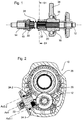
- Fig. 1 shows a gear shift of a preferred embodiment of a power tool according to the present invention in a side view sectional view.
- a Taumeltriebnabe 16 On a horizontally extending drive shaft 12, a Taumeltriebnabe 16, a countershaft gear 14, a first coupling sleeve 18 and a second coupling sleeve 20 is mounted freewheeling.
- the two coupling sleeves 18, 20 are thereby pressed apart and into engagement with the countershaft gearwheel 14 or the wobble drive hub 16 by a helical spring 28, which is mounted in a free-running manner between the two coupling sleeves 18, 20 on the drive shaft 12.
- the spring 28 acts on the coupling sleeves 18, 20 so in opposite directions. Unlike the countershaft gear 14 and the Taumeltriebnabe 16, the coupling sleeves 18, 20 are positively connected to the drive shaft 12 via a gear contour 30, 32 of the drive shaft 12. A rotation of the drive shaft 12 thus leads directly to a rotation of the two coupling sleeves 18, 20th Fig. 1 shows a state in which the coupling sleeves 18, 20 also in each case with the countershaft gear 14 and the Taumeltechnischnabe 16 are positively engaged.
- the journal 34 of the wobble drive which is in a linear guide, is moved back and forth and causes a striking movement in a drill spindle 44 (FIG. Fig. 3 . 5 . 7 ) clamped tool.
- the countershaft gear 14 is rotationally coupled to the drill spindle 44 of the power tool 10 so that rotation of the drive shaft 12, which is transmitted to the countershaft gear 14 via the coupling sleeve 18, results in rotation of the drill spindle 44.
- Fig. 2 shows a further sectional view of the power tool 10 according to the preferred embodiment Fig. 1 ,
- the section is made perpendicular to the drive shaft 12 in the height of the coupling sleeve 20 along the cutting plane S1 and the representation is shown as a projection from the rear, ie of the coupling sleeve 20 in the direction of the coupling sleeve 18.
- a stationary gear 26 is shown next to the drive shaft 12 and the coupling sleeve 20, which is in engagement with the countershaft gear 14 and transmits the rotational movement of the countershaft gear 14 to the drill spindle 44.
- This stationary gear 26 encloses an axis Ax1 ( Fig. 3 . 5 . 7 ), along which the impact movement of the wobble drive is transferred to the tool clamped in the drill spindle 44 via an impact cylinder 40 and around which the drill spindle 44 rotates.
- Fig. 2 an actuator 22 which is in the form of a rotary switch.
- the rotary switch 22 has two pins 24.1, 24.2, which can be brought into contact with the coupling sleeves 18, 20.
- the first pin 24.1 in contact with the coupling sleeve 20 by against the projecting portion of the Coupling sleeve 20 strikes in the direction of the drive shaft 12 and the coupling sleeve 20 thus moves along the drive shaft 12.
- the projecting portion of the coupling sleeve 20 is designed rotationally symmetrical about the drive shaft 12 and provides a contact surface for the pin 24.1. Due to the circular ring shape of the contact surface of the coupling sleeve 20, the coupling sleeve 20 can also rotate about the drive shaft 12 without the contact between the Pin 24.1 and the coupling sleeve 20 is changed.
- the pin 24.1 is arranged and aligned such that it protrudes parallel to the axis of rotation Ax2 of the rotary switch 22 and defines an axis Ax3.1, which extends substantially radially to the drive axis 12.
- the analogous applies to the second pin 24.2, with the axis Ax3.2 defined by this pin only in the engaged state with the coupling sleeve 18 which is in Fig. 2 not shown, extends radially to the drive axle 12.
- the axis Ax1.2 extends parallel to the axis of rotation Ax2 of the rotary switch 22 and the axis defined by the first pin Ax3.1.
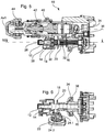
- Fig. 3 shows a sectional view of a side view of the power tool Figures 1 and 2 ,
- the change gear Fig. 1 can be recognized here in the lower part of the power tool.
- the gearbox is also in the same state as in Fig. 1 , so that a detailed description of the elements used in this case is unnecessary.
- Fig. 1 shows Fig. 3
- a locking plate 38 can be seen, which in the in Fig. 3 illustrated state, however, no arresting function perceives.
- the drive shaft 12 serves both the drive of the Taumeltriebnabe 16, as well as the drive of the countershaft gear 14th
- the Taumeltriebnabe 16 results in its rotation to a forward and backward-striking movement of the Taumeltriebzapfens 34, which is mounted on the ball bearing 36 on the Taumeltriebnabe 16 and guided in a direction parallel to the drive shaft 12 linear guide.
- the forward / backward movement of the pin 34 continues on a percussion cylinder 40 which is guided in a percussion guide, the percussion guide extending parallel to the drive axle 12 along the axis Ax1.
- the impact cylinder 40 strikes in the forward movement of the wobble pin 34 on an anvil 42, which in turn transmits the impact force to a clamped in the drill spindle 44 tool.
- the rotation of the drive shaft 12 results in a rotation of the countershaft gear 14 which engages the stationary gear 26.
- the stationary gear 26 encloses the impact axis Ax1 of the power tool 10 and the impact cylinder 40 therein and the striker 42.
- the stationary gear 26, the drill spindle 44 is splined, so that the rotational movement of the stationary gear 26 and the drill spindle 44 and the clamped therein Tool set in rotation, regardless of whether the tool in the drill spindle 44 is acted upon by the impact cylinder 40 and striker 42 or not.
- the in Fig. 3 illustrated state of the power tool 10 thus corresponds to the combined drilling and chiseling operation of the power tool 10, in which a clamped in the drill spindle 44 tool is driven on the one hand to a drilling movement and on the other hand acted upon from the rear with impact forces.
- Fig. 4 shows a further sectional view along the cutting plane S2 in FIG Fig. 3 , It is thus shown a plan view of a sectional view, wherein the section along the drive shaft 12 extends.
- the drive shaft 12 As in the FIGS. 1 and 3 , are also in Fig. 4 the drive shaft 12, the countershaft gear 14, the Taumeltriebnabe 16 and the coupling sleeves 18 and 20 shown.
- the rotary switch 22 which is already in Fig. 2 is shown.
- the rotary switch 22 is provided with the two pins 24.1, 24.2, which are both out of engagement with the respective coupling sleeve 20, 18.
- the coupling sleeves 18, 20 so in engagement with their respective output element, the countershaft gear 14 and the Taumeltriebnabe 16, because none of the pins 24.1, 24.2 of the rotary switch 22 with one of the coupling sleeves 18, 20 in contact and the acted upon force on the coupling sleeves 18, 20 counteracts.
- Fig. 4 Thus, Fig. 1 shows the position of the rotary switch 22, which allows a combined drilling and chiseling operation of the power tool 10.
- Fig. 5 shows the view Fig. 3 of the power tool 10 according to the preferred embodiment of the invention.
- Fig. 3 shows Fig. 5
- a state in which the coupling sleeve 20, which is provided for transmitting the driving force of the drive shaft 12 to the Taumeltriebnabe 16 is disengaged.
- the coupling sleeve 20 is in the in Fig. 5 shown state to the left, moved in the direction of the coupling sleeve 18.
- Fig. 6 corresponds to the representation of Fig. 4 of the power tool 10 in the state that is in Fig. 5 is shown. It can be clearly seen that the rotary switch 22 by the pin 24.1, which is mounted on the rotary switch 22, acts on the coupling sleeve 20. The second pin 24.2 of the rotary switch 22 is not engaged with the coupling sleeve 18, so that the power transmission between the drive shaft 12 and the countershaft gear 14 is ensured via the coupling sleeve 18.
- the in FIGS. 5 and 6 illustrated state of the power tool corresponds to a rotation of the rotary switch 22 from the combined drilling and bit position by 90 ° to the right, thus deactivating the chisel function of the power tool.
- Fig. 7 shows the power tool 10 in the same view as Figures 3 and 5 However, in a state in which the coupling sleeve 20 is in engagement with the Taumeltriebnabe 16, but the coupling sleeve 18 is disengaged from the countershaft gear 14. The coupling sleeve 18 is in the in Fig. 7 shown state to the right, moved in the direction of the coupling sleeve 20.
- rotary switch 22 holds the locking plate 38 both in the combined drilling and chiseling mode, as well as in the pure drilling state of the power tool out of engagement with the countershaft gear 14 and allows locking of the countershaft gear 14 only in the event of disengagement of the coupling sleeve 18.
- the countershaft gear 14 is decoupled from the rotational movement of the drive shaft 12, so that the drive shaft 12 is independent of the locking of the countershaft gear 14 is rotatable.
- FIG. 7 shows that the coupling sleeve 20 is in engagement with the wobble drive hub 16.
- the in Fig. 7 shown state of the power tool 10 of the wobble drive on the Taumeltriebnabe 16 the ball bearing 36 and the Taumeltriebzapfen 34 operated and leads to a striking movement of the impact cylinder 40 and the striker 42 on the clamped in the drill spindle 44 tool.
- Fig. 8 that the view of FIGS. 4 and 6 is analogous, the rotary switch 22 is shown, the second pin 24.2 is in contact with the coupling sleeve 18.
- Analogous to in Fig. 6 shown state of the power tool 10 is here the coupling sleeve 18 by the contact between the pin 24.2 and the projecting portion of the Coupling sleeve 18 is brought out of engagement with the countershaft gear 14.
- the coupling sleeve 20 is not contacted by the pin 24.1 of the knob 22 and is therefore in engagement with the Taumeltriebnabe sixteenth
- the rotary switch 22 is designed as a substantially circular element having a handle portion for rotating the rotary switch on its outwardly facing part.
- the two pins 24.1, 24.2 are present at its innermost lying surface.
- the pins 24.1, 24.2 are made in one piece with the rotary switch 22.
- the inward-facing part of the rotary switch 22 has a substantially cylindrical shape, wherein a part of the cylindrical portion is secant cut off. In this way, a smooth stop surface, which is formed on one side of the inwardly projecting part of the knob 22. In this angular range, the peripheral surface of the inwardly projecting part of the rotary switch 22 thus does not extend in the manner of a cylinder jacket, but rather.
Claims (15)
- Outil électronique (10), en particulier marteau perforateur et burineur, comprenant un arbre entraînement (12) et deux éléments entraînés (14, 16), dans lequel l'arbre d'entraînement (12) peut être relié de manière active aux éléments entraînés (14, 16), respectivement par le biais d'un manchon de couplage (18, 20) de l'outil électrique (10), dans lequel les manchons de couplage (18, 20) peuvent être actionnés par un élément d'actionnement (22) rotatif mécanique de l'outil électrique (10), en particulier un commutateur rotatif (22) mécanique, dans lequel l'élément d'actionnement (22) comprend un dispositif de transmission (24.1, 24.2) fixe par rapport à l'élément d'actionnement (22), qui peut être mis en contact direct avec le manchon de couplage (18, 20) respectif pour actionner un des manchons de couplage (18, 20),
caractérisé en ce que l'un élément entraîné (14) peut être bloqué contre un mouvement de rotation par un dispositif de blocage (38) de l'outil électrique (10), dans lequel le dispositif de blocage (38) conçu en tant que tôle de blocage est alimenté par une force de ressort en direction des manchons de couplage (20), et l'élément d'actionnement (22) conçu en tant que commutateur rotatif est équipé pour ne permettre un blocage de l'élément entraîné (14) respectif que lorsque le manchon de couplage (18) correspondant est désaccouplé. - Outil électrique (10) selon la revendication 1,
caractérisé en ce que l'élément d'actionnement (22) présente une face de butée plane par laquelle le dispositif de blocage (38) est mobile en direction des manchons de couplage (18, 20), dans lequel le dispositif de blocage (38) peut sinon être appuyé contre une partie formant une enveloppe de cylindre de l'élément d'actionnement (22). - Outil électrique (10) selon la revendication 1,
caractérisé en ce que les manchons de couplage (18, 20) sont disposés en étant mobiles axialement sur l'arbre d'entraînement (12). - Outil électrique (10) selon l'une des revendications 1 à 3, caractérisé en ce que les éléments entraînés (14, 16) sont disposés en roue libre sur l'arbre d'entraînement (12).
- Outil électrique (10) selon l'une des revendications 1 à 4, caractérisé en ce que les manchons de couplage (18, 20) sont conçus pour créer une liaison active à engagement positif entre l'arbre d'entraînement (12) et les éléments entraînés (14, 16).
- Outil électrique (10) selon l'une des revendications 1 à 5, caractérisé en ce que les manchons de couplage (18, 20) sont alimentés en direction respectivement d'une première position dans laquelle l'arbre d'entraînement (12) et l'élément entraîné (14, 16) respectif sont en liaison active l'un avec l'autre, dans lequel les premières positions respectives sont axialement opposées de préférence.
- Outil électrique (10) selon l'une des revendications 1 à 6, caractérisé en ce que les manchons de couplage (18, 20) peuvent être amenés, par le biais du dispositif de transmission (24.1, 24.2) par l'élément d'actionnement (22), dans respectivement une seconde position dans laquelle l'arbre d'entraînement (12) et l'élément entraîné (14, 16) respectif ne sont pas en liaison active l'un avec l'autre.
- Outil électrique (10) selon l'une des revendications 1 à 7, caractérisé en ce que le dispositif de transmission (24.1, 24.2) peut être amené en contact direct avec l'un des manchons de couplage (18, 20) au choix.
- Outil électrique (10) selon l'une des revendications 1 à 8, caractérisé en ce que le dispositif de transmission (24.1, 24.2) est formé par au moins une saillie (24.1, 24.2), de préférence deux saillies (24.1, 24.2), dans lequel la saillie (24.1, 24.2) s'étend de préférence parallèlement au pivot (Ax2) de l'élément d'actionnement (22).
- Outil électrique (10) selon la revendication 9, caractérisé en ce que la saillie (24.1, 24.2) est formée par une broche (24.1, 24.2) qui est formée de préférence d'un seul bloc avec l'élément d'actionnement (22).
- Outil électrique (10) selon l'une des revendications 1 à 10, caractérisé en ce que l'élément d'actionnement (22) est formé pour sélectionner trois états de couplage différents entre l'arbre d'entraînement (12) et les deux éléments entraînés (14, 16).
- Outil électrique (10) selon l'une des revendications 1 à 11, caractérisé en ce que le pivot (Ax2) de l'élément d'actionnement (22) est essentiellement parallèle à un axe radial de l'arbre d'entraînement (12).
- Outil électrique (10) selon l'une des revendications 1 à 12 et selon la revendication 8, dans lequel la saillie (24.1, 24.2) s'étend parallèlement au pivot (Ax2) de l'élément d'actionnement (22), caractérisé en ce que la saillie (24.1, 24.2), dans une des positions de contact avec un des manchons de couplage (18, 20), s'étend essentiellement le long d'un axe radial par rapport à l'arbre d'entraînement (12).
- Outil électrique (10) selon l'une des revendications 1 à 13, caractérisé en ce que les éléments actionnés (14, 16) sont un pignon de renvoi (14) et un moyeu à commande oscillante (16).
- Outil électrique (10) selon la revendication 14, caractérisé en ce que l'élément d'actionnement (22) passe alternativement entre un premier état dans lequel l'outil électrique (10) exécute un mouvement de rotation du pignon de renvoi (14) sans déplacer le moyeu à commande oscillante (16), un deuxième état dans lequel l'outil électrique (10) exécute un mouvement du moyeu à commande oscillante (16), dans lequel le pignon de renvoi (14) est fixe en rotation, et un troisième état dans lequel l'outil électrique (10) exécute un mouvement simultané du pignon de renvoi (14) et du moyeu à commande oscillante (16) .
Priority Applications (3)
| Application Number | Priority Date | Filing Date | Title |
|---|---|---|---|
| EP08161170.9A EP2147753B1 (fr) | 2008-07-25 | 2008-07-25 | Outil électrique doté d'une commutation de transmission |
| US12/509,402 US8230943B2 (en) | 2008-07-25 | 2009-07-24 | Electrical tool with gear switching |
| CN2009101573461A CN101633163B (zh) | 2008-07-25 | 2009-07-27 | 具有传动转换器的电动工具 |
Applications Claiming Priority (1)
| Application Number | Priority Date | Filing Date | Title |
|---|---|---|---|
| EP08161170.9A EP2147753B1 (fr) | 2008-07-25 | 2008-07-25 | Outil électrique doté d'une commutation de transmission |
Publications (2)
| Publication Number | Publication Date |
|---|---|
| EP2147753A1 EP2147753A1 (fr) | 2010-01-27 |
| EP2147753B1 true EP2147753B1 (fr) | 2017-01-18 |
Family
ID=40130506
Family Applications (1)
| Application Number | Title | Priority Date | Filing Date |
|---|---|---|---|
| EP08161170.9A Active EP2147753B1 (fr) | 2008-07-25 | 2008-07-25 | Outil électrique doté d'une commutation de transmission |
Country Status (3)
| Country | Link |
|---|---|
| US (1) | US8230943B2 (fr) |
| EP (1) | EP2147753B1 (fr) |
| CN (1) | CN101633163B (fr) |
Families Citing this family (14)
| Publication number | Priority date | Publication date | Assignee | Title |
|---|---|---|---|---|
| US8800835B2 (en) * | 2008-07-17 | 2014-08-12 | Stanley Fastening Systems, Lp | Fastener driving device with mode selector and trigger interlock |
| CN101758486B (zh) * | 2010-01-21 | 2011-09-28 | 浙江海王电器有限公司 | 轻型单钮多功能电锤 |
| DE102010002672A1 (de) * | 2010-03-09 | 2011-09-15 | Robert Bosch Gmbh | Bohrhammervorrichtung |
| US9393711B2 (en) * | 2011-04-11 | 2016-07-19 | Milwaukee Electric Tool Corporation | Hand-held knockout punch driver |
| CN102784949A (zh) * | 2011-05-19 | 2012-11-21 | 博世电动工具(中国)有限公司 | 电动工具及其传动机构 |
| KR101317138B1 (ko) * | 2011-12-09 | 2013-10-18 | 기아자동차주식회사 | 전기자동차의 에코 드라이빙 시스템 및 그 방법 |
| DE102012209446A1 (de) * | 2012-06-05 | 2013-12-05 | Robert Bosch Gmbh | Handwerkzeugmaschinenvorrichtung |
| US9630307B2 (en) | 2012-08-22 | 2017-04-25 | Milwaukee Electric Tool Corporation | Rotary hammer |
| DE102012214938B4 (de) * | 2012-08-22 | 2016-11-10 | Metabowerke Gmbh | Getriebeanordnung für eine angetriebene Werkzeugmaschine sowie Werkzeugmaschine mit einer solchen Getriebeanordnung |
| CN103894983A (zh) * | 2012-12-26 | 2014-07-02 | 株式会社牧田 | 电锤 |
| CN203471741U (zh) | 2013-09-13 | 2014-03-12 | 王国雄 | 电钻转接头 |
| US10518399B2 (en) * | 2015-09-30 | 2019-12-31 | Chervon (Hk) Limited | Clutch device and power tool with clutch device |
| WO2018020283A1 (fr) * | 2016-07-27 | 2018-02-01 | BEREGSZASZI, David | Dispositif de conversion de mouvement |
| US11826891B2 (en) * | 2019-10-21 | 2023-11-28 | Makita Corporation | Power tool having hammer mechanism |
Family Cites Families (17)
| Publication number | Priority date | Publication date | Assignee | Title |
|---|---|---|---|---|
| KR920010874B1 (ko) | 1988-03-03 | 1992-12-19 | 히다찌 겐끼 가부시기가이샤 | 유압기계의 유압구동방법 및 유압구동장치 |
| JPH06108770A (ja) * | 1992-08-31 | 1994-04-19 | Sig (Schweiz Ind Ges) | ロックドリル用ドリル装置 |
| JPH0970771A (ja) | 1995-09-08 | 1997-03-18 | Hitachi Koki Co Ltd | ハンマドリルの動作モード切換装置 |
| JP3098963B2 (ja) * | 1996-02-09 | 2000-10-16 | リョービ株式会社 | 回転工具の動作切り換え機構 |
| ES2216160T3 (es) * | 1996-07-18 | 2004-10-16 | Implant Innovations, Inc. | Utiles de osteotomia provistos de motor de compactacion de tejido oseo. |
| US6536536B1 (en) * | 1999-04-29 | 2003-03-25 | Stephen F. Gass | Power tools |
| JP3843914B2 (ja) * | 2002-08-27 | 2006-11-08 | 松下電工株式会社 | ハンマードリル |
| JP3976187B2 (ja) * | 2002-11-20 | 2007-09-12 | 株式会社マキタ | ハンマードリル |
| DE102004020177A1 (de) * | 2004-04-24 | 2005-11-17 | Robert Bosch Gmbh | Handwerkzeugmaschine mit einem drehenden und/oder schlagenden Antrieb |
| GB0428210D0 (en) * | 2004-12-23 | 2005-01-26 | Black & Decker Inc | Mode change mechanism |
| EP1674207B1 (fr) * | 2004-12-23 | 2008-12-10 | BLACK & DECKER INC. | Outil motorisé |
| JP4735106B2 (ja) * | 2005-07-29 | 2011-07-27 | パナソニック電工株式会社 | 電動工具 |
| DE102005041448A1 (de) * | 2005-08-31 | 2007-03-01 | Robert Bosch Gmbh | Handbohrmaschine mit Schaltgetriebe |
| DE102005056205A1 (de) * | 2005-11-25 | 2007-06-06 | Robert Bosch Gmbh | Bohrhammer mit drei Betriebsarten |
| EP1882553B1 (fr) * | 2006-07-26 | 2011-09-21 | Hitachi Koki Co., Ltd. | Outil électrique doté d'une lumière |
| DE102006056849A1 (de) * | 2006-12-01 | 2008-06-05 | Robert Bosch Gmbh | Handwerkzeugmaschine |
| DE102007001494B3 (de) * | 2007-01-10 | 2008-07-10 | Aeg Electric Tools Gmbh | Handgeführter Bohrhammer |
-
2008
- 2008-07-25 EP EP08161170.9A patent/EP2147753B1/fr active Active
-
2009
- 2009-07-24 US US12/509,402 patent/US8230943B2/en active Active
- 2009-07-27 CN CN2009101573461A patent/CN101633163B/zh not_active Expired - Fee Related
Non-Patent Citations (1)
| Title |
|---|
| None * |
Also Published As
| Publication number | Publication date |
|---|---|
| CN101633163B (zh) | 2013-07-24 |
| EP2147753A1 (fr) | 2010-01-27 |
| US20100025059A1 (en) | 2010-02-04 |
| US8230943B2 (en) | 2012-07-31 |
| CN101633163A (zh) | 2010-01-27 |
Similar Documents
| Publication | Publication Date | Title |
|---|---|---|
| EP2147753B1 (fr) | Outil électrique doté d'une commutation de transmission | |
| EP1578564B1 (fr) | Marteau perforateur | |
| DE4236819C2 (de) | Motorisch angetriebene Drehwerkzeugeinrichtung | |
| DE19944294B4 (de) | Fremdkraftgetriebener Bohrhammer mit verbessertem Betriebsmodusumschalter | |
| DE102004018084B3 (de) | Hammerbohrgerät | |
| DE10041410B4 (de) | Bohrhammer mit einem Mechanismus zur Einstellung einer Betriebsart | |
| EP1957240B1 (fr) | Marteau perforateur avec trois modes de fonctionnement | |
| DE60120006T2 (de) | Elektrisches Handwerkzeug | |
| DE602005004980T2 (de) | Elektrowerkzeug mit Betriebsartenwahlschalter zur Auswahl einer aus mehreren Betriebsarten | |
| EP2291267B1 (fr) | Machine-outil pourvue d'un dispositif d'embrayage | |
| EP1765556B1 (fr) | Marteau de percussion et/ou de perforation a accouplement de securite | |
| CH697940B1 (de) | Handwerkzeugmaschine, insbesondere Bohr- und/oder Schlaghammer. | |
| DE102007009986A1 (de) | Handwerkzeugmaschine | |
| DE102006056849A1 (de) | Handwerkzeugmaschine | |
| DE19805924A1 (de) | Getriebe | |
| EP2628571B1 (fr) | Machine-outil portative | |
| EP2869733B1 (fr) | Dispositif de commande d'un système d'entraînement pour meuble | |
| EP0437716A1 (fr) | Outil à main entraîné électriquement | |
| DE102012214938B4 (de) | Getriebeanordnung für eine angetriebene Werkzeugmaschine sowie Werkzeugmaschine mit einer solchen Getriebeanordnung | |
| EP1632314A2 (fr) | Commutateur avec un ressort de synchronisation | |
| DE4406841C1 (de) | Hammerbohrmaschine | |
| DE102004052329A1 (de) | Synchronisations- und Schalteinheit für Einknopf-Wahlschalter sowie Elektrowerkzeug mit Synchronisations- und Schalteinheit | |
| WO2012084669A1 (fr) | Machine-outil à main | |
| EP2347865A1 (fr) | Outil électrique | |
| EP0972665B9 (fr) | Dispositif pour le verrouillage d'un élément de fermeture d'un véhicule |
Legal Events
| Date | Code | Title | Description |
|---|---|---|---|
| PUAI | Public reference made under article 153(3) epc to a published international application that has entered the european phase |
Free format text: ORIGINAL CODE: 0009012 |
|
| AK | Designated contracting states |
Kind code of ref document: A1 Designated state(s): AT BE BG CH CY CZ DE DK EE ES FI FR GB GR HR HU IE IS IT LI LT LU LV MC MT NL NO PL PT RO SE SI SK TR |
|
| AX | Request for extension of the european patent |
Extension state: AL BA MK RS |
|
| 17P | Request for examination filed |
Effective date: 20100723 |
|
| AKX | Designation fees paid |
Designated state(s): DE FR GB IT |
|
| 17Q | First examination report despatched |
Effective date: 20101210 |
|
| GRAP | Despatch of communication of intention to grant a patent |
Free format text: ORIGINAL CODE: EPIDOSNIGR1 |
|
| INTG | Intention to grant announced |
Effective date: 20160909 |
|
| GRAS | Grant fee paid |
Free format text: ORIGINAL CODE: EPIDOSNIGR3 |
|
| GRAA | (expected) grant |
Free format text: ORIGINAL CODE: 0009210 |
|
| AK | Designated contracting states |
Kind code of ref document: B1 Designated state(s): DE FR GB IT |
|
| REG | Reference to a national code |
Ref country code: GB Ref legal event code: FG4D Free format text: NOT ENGLISH |
|
| REG | Reference to a national code |
Ref country code: DE Ref legal event code: R096 Ref document number: 502008014970 Country of ref document: DE |
|
| REG | Reference to a national code |
Ref country code: DE Ref legal event code: R097 Ref document number: 502008014970 Country of ref document: DE |
|
| PG25 | Lapsed in a contracting state [announced via postgrant information from national office to epo] |
Ref country code: IT Free format text: LAPSE BECAUSE OF FAILURE TO SUBMIT A TRANSLATION OF THE DESCRIPTION OR TO PAY THE FEE WITHIN THE PRESCRIBED TIME-LIMIT Effective date: 20170118 |
|
| PLBE | No opposition filed within time limit |
Free format text: ORIGINAL CODE: 0009261 |
|
| STAA | Information on the status of an ep patent application or granted ep patent |
Free format text: STATUS: NO OPPOSITION FILED WITHIN TIME LIMIT |
|
| 26N | No opposition filed |
Effective date: 20171019 |
|
| GBPC | Gb: european patent ceased through non-payment of renewal fee |
Effective date: 20170725 |
|
| REG | Reference to a national code |
Ref country code: FR Ref legal event code: ST Effective date: 20180330 |
|
| PG25 | Lapsed in a contracting state [announced via postgrant information from national office to epo] |
Ref country code: GB Free format text: LAPSE BECAUSE OF NON-PAYMENT OF DUE FEES Effective date: 20170725 |
|
| PG25 | Lapsed in a contracting state [announced via postgrant information from national office to epo] |
Ref country code: FR Free format text: LAPSE BECAUSE OF NON-PAYMENT OF DUE FEES Effective date: 20170731 |
|
| P01 | Opt-out of the competence of the unified patent court (upc) registered |
Effective date: 20230612 |
|
| PGFP | Annual fee paid to national office [announced via postgrant information from national office to epo] |
Ref country code: DE Payment date: 20230830 Year of fee payment: 16 |