EP4219082A1 - Rotary power tool - Google Patents
Rotary power tool Download PDFInfo
- Publication number
- EP4219082A1 EP4219082A1 EP23176165.1A EP23176165A EP4219082A1 EP 4219082 A1 EP4219082 A1 EP 4219082A1 EP 23176165 A EP23176165 A EP 23176165A EP 4219082 A1 EP4219082 A1 EP 4219082A1
- Authority
- EP
- European Patent Office
- Prior art keywords
- housing
- power tool
- spindle
- fluid
- handle
- Prior art date
- Legal status (The legal status is an assumption and is not a legal conclusion. Google has not performed a legal analysis and makes no representation as to the accuracy of the status listed.)
- Pending
Links
- 239000012530 fluid Substances 0.000 claims abstract description 58
- 230000004044 response Effects 0.000 claims abstract description 10
- 238000004891 communication Methods 0.000 claims description 2
- 230000005540 biological transmission Effects 0.000 description 14
- 238000001816 cooling Methods 0.000 description 8
- 230000007246 mechanism Effects 0.000 description 7
- 230000009467 reduction Effects 0.000 description 7
- 238000009826 distribution Methods 0.000 description 6
- 239000000428 dust Substances 0.000 description 5
- 239000002783 friction material Substances 0.000 description 5
- 238000006243 chemical reaction Methods 0.000 description 4
- 238000000034 method Methods 0.000 description 3
- 230000008569 process Effects 0.000 description 3
- 239000004809 Teflon Substances 0.000 description 2
- 229920006362 Teflon® Polymers 0.000 description 2
- 230000008878 coupling Effects 0.000 description 2
- 238000010168 coupling process Methods 0.000 description 2
- 238000005859 coupling reaction Methods 0.000 description 2
- 238000005553 drilling Methods 0.000 description 2
- 239000000463 material Substances 0.000 description 2
- 230000007935 neutral effect Effects 0.000 description 2
- 239000012255 powdered metal Substances 0.000 description 2
- ZOXJGFHDIHLPTG-UHFFFAOYSA-N Boron Chemical compound [B] ZOXJGFHDIHLPTG-UHFFFAOYSA-N 0.000 description 1
- WHXSMMKQMYFTQS-UHFFFAOYSA-N Lithium Chemical compound [Li] WHXSMMKQMYFTQS-UHFFFAOYSA-N 0.000 description 1
- 229910052796 boron Inorganic materials 0.000 description 1
- 238000005056 compaction Methods 0.000 description 1
- 238000010276 construction Methods 0.000 description 1
- 230000000994 depressogenic effect Effects 0.000 description 1
- 238000004512 die casting Methods 0.000 description 1
- 229910052744 lithium Inorganic materials 0.000 description 1
- 238000005461 lubrication Methods 0.000 description 1
- 238000003754 machining Methods 0.000 description 1
- 238000005259 measurement Methods 0.000 description 1
- 238000005245 sintering Methods 0.000 description 1
- 125000006850 spacer group Chemical group 0.000 description 1
- 239000007921 spray Substances 0.000 description 1
- XLYOFNOQVPJJNP-UHFFFAOYSA-N water Substances O XLYOFNOQVPJJNP-UHFFFAOYSA-N 0.000 description 1
Images


Classifications
-
- B—PERFORMING OPERATIONS; TRANSPORTING
- B23—MACHINE TOOLS; METAL-WORKING NOT OTHERWISE PROVIDED FOR
- B23B—TURNING; BORING
- B23B45/00—Hand-held or like portable drilling machines, e.g. drill guns; Equipment therefor
-
- B—PERFORMING OPERATIONS; TRANSPORTING
- B23—MACHINE TOOLS; METAL-WORKING NOT OTHERWISE PROVIDED FOR
- B23Q—DETAILS, COMPONENTS, OR ACCESSORIES FOR MACHINE TOOLS, e.g. ARRANGEMENTS FOR COPYING OR CONTROLLING; MACHINE TOOLS IN GENERAL CHARACTERISED BY THE CONSTRUCTION OF PARTICULAR DETAILS OR COMPONENTS; COMBINATIONS OR ASSOCIATIONS OF METAL-WORKING MACHINES, NOT DIRECTED TO A PARTICULAR RESULT
- B23Q11/00—Accessories fitted to machine tools for keeping tools or parts of the machine in good working condition or for cooling work; Safety devices specially combined with or arranged in, or specially adapted for use in connection with, machine tools
- B23Q11/10—Arrangements for cooling or lubricating tools or work
- B23Q11/1015—Arrangements for cooling or lubricating tools or work by supplying a cutting liquid through the spindle
-
- B—PERFORMING OPERATIONS; TRANSPORTING
- B25—HAND TOOLS; PORTABLE POWER-DRIVEN TOOLS; MANIPULATORS
- B25F—COMBINATION OR MULTI-PURPOSE TOOLS NOT OTHERWISE PROVIDED FOR; DETAILS OR COMPONENTS OF PORTABLE POWER-DRIVEN TOOLS NOT PARTICULARLY RELATED TO THE OPERATIONS PERFORMED AND NOT OTHERWISE PROVIDED FOR
- B25F5/00—Details or components of portable power-driven tools not particularly related to the operations performed and not otherwise provided for
- B25F5/02—Construction of casings, bodies or handles
- B25F5/025—Construction of casings, bodies or handles with torque reaction bars for rotary tools
- B25F5/026—Construction of casings, bodies or handles with torque reaction bars for rotary tools in the form of an auxiliary handle
-
- B—PERFORMING OPERATIONS; TRANSPORTING
- B23—MACHINE TOOLS; METAL-WORKING NOT OTHERWISE PROVIDED FOR
- B23B—TURNING; BORING
- B23B2250/00—Compensating adverse effects during turning, boring or drilling
- B23B2250/12—Cooling and lubrication
-
- B—PERFORMING OPERATIONS; TRANSPORTING
- B23—MACHINE TOOLS; METAL-WORKING NOT OTHERWISE PROVIDED FOR
- B23B—TURNING; BORING
- B23B2260/00—Details of constructional elements
- B23B2260/024—Batteries
-
- B—PERFORMING OPERATIONS; TRANSPORTING
- B23—MACHINE TOOLS; METAL-WORKING NOT OTHERWISE PROVIDED FOR
- B23B—TURNING; BORING
- B23B45/00—Hand-held or like portable drilling machines, e.g. drill guns; Equipment therefor
- B23B45/001—Housing of the drill, e.g. handgrip
-
- B—PERFORMING OPERATIONS; TRANSPORTING
- B23—MACHINE TOOLS; METAL-WORKING NOT OTHERWISE PROVIDED FOR
- B23B—TURNING; BORING
- B23B45/00—Hand-held or like portable drilling machines, e.g. drill guns; Equipment therefor
- B23B45/008—Gear boxes, clutches, bearings, feeding mechanisms or like equipment
-
- B—PERFORMING OPERATIONS; TRANSPORTING
- B23—MACHINE TOOLS; METAL-WORKING NOT OTHERWISE PROVIDED FOR
- B23B—TURNING; BORING
- B23B45/00—Hand-held or like portable drilling machines, e.g. drill guns; Equipment therefor
- B23B45/02—Hand-held or like portable drilling machines, e.g. drill guns; Equipment therefor driven by electric power
-
- B—PERFORMING OPERATIONS; TRANSPORTING
- B23—MACHINE TOOLS; METAL-WORKING NOT OTHERWISE PROVIDED FOR
- B23B—TURNING; BORING
- B23B51/00—Tools for drilling machines
- B23B51/04—Drills for trepanning
- B23B51/0486—Drills for trepanning with lubricating or cooling equipment
-
- B—PERFORMING OPERATIONS; TRANSPORTING
- B23—MACHINE TOOLS; METAL-WORKING NOT OTHERWISE PROVIDED FOR
- B23Q—DETAILS, COMPONENTS, OR ACCESSORIES FOR MACHINE TOOLS, e.g. ARRANGEMENTS FOR COPYING OR CONTROLLING; MACHINE TOOLS IN GENERAL CHARACTERISED BY THE CONSTRUCTION OF PARTICULAR DETAILS OR COMPONENTS; COMBINATIONS OR ASSOCIATIONS OF METAL-WORKING MACHINES, NOT DIRECTED TO A PARTICULAR RESULT
- B23Q11/00—Accessories fitted to machine tools for keeping tools or parts of the machine in good working condition or for cooling work; Safety devices specially combined with or arranged in, or specially adapted for use in connection with, machine tools
- B23Q11/10—Arrangements for cooling or lubricating tools or work
- B23Q11/1015—Arrangements for cooling or lubricating tools or work by supplying a cutting liquid through the spindle
- B23Q11/1023—Tool holders, or tools in general specially adapted for receiving the cutting liquid from the spindle
-
- B—PERFORMING OPERATIONS; TRANSPORTING
- B25—HAND TOOLS; PORTABLE POWER-DRIVEN TOOLS; MANIPULATORS
- B25F—COMBINATION OR MULTI-PURPOSE TOOLS NOT OTHERWISE PROVIDED FOR; DETAILS OR COMPONENTS OF PORTABLE POWER-DRIVEN TOOLS NOT PARTICULARLY RELATED TO THE OPERATIONS PERFORMED AND NOT OTHERWISE PROVIDED FOR
- B25F5/00—Details or components of portable power-driven tools not particularly related to the operations performed and not otherwise provided for
- B25F5/008—Cooling means
-
- Y—GENERAL TAGGING OF NEW TECHNOLOGICAL DEVELOPMENTS; GENERAL TAGGING OF CROSS-SECTIONAL TECHNOLOGIES SPANNING OVER SEVERAL SECTIONS OF THE IPC; TECHNICAL SUBJECTS COVERED BY FORMER USPC CROSS-REFERENCE ART COLLECTIONS [XRACs] AND DIGESTS
- Y10—TECHNICAL SUBJECTS COVERED BY FORMER USPC
- Y10T—TECHNICAL SUBJECTS COVERED BY FORMER US CLASSIFICATION
- Y10T408/00—Cutting by use of rotating axially moving tool
- Y10T408/44—Cutting by use of rotating axially moving tool with means to apply transient, fluent medium to work or product
- Y10T408/45—Cutting by use of rotating axially moving tool with means to apply transient, fluent medium to work or product including Tool with duct
- Y10T408/455—Conducting channel extending to end of Tool
-
- Y—GENERAL TAGGING OF NEW TECHNOLOGICAL DEVELOPMENTS; GENERAL TAGGING OF CROSS-SECTIONAL TECHNOLOGIES SPANNING OVER SEVERAL SECTIONS OF THE IPC; TECHNICAL SUBJECTS COVERED BY FORMER USPC CROSS-REFERENCE ART COLLECTIONS [XRACs] AND DIGESTS
- Y10—TECHNICAL SUBJECTS COVERED BY FORMER USPC
- Y10T—TECHNICAL SUBJECTS COVERED BY FORMER US CLASSIFICATION
- Y10T408/00—Cutting by use of rotating axially moving tool
- Y10T408/91—Machine frame
Definitions
- the present invention relates to rotary power tools, and more particularly to core drills.
- Core drills are typically used to remove a cylinder of material from a workpiece.
- the present invention provides, in one aspect, a core drill including a housing, a first handle extending from the housing and defining a gap between the handle and the housing, a motor supported within the housing, and a battery removably coupled to the housing and configured to provide power to the motor.
- the battery has an output voltage greater than 40 volts.
- the core drill further includes a spindle configured to rotate about a rotational axis in response to torque received from the motor and a fluid delivery system configured to supply fluid to the spindle.
- the fluid delivery system includes an operable valve to regulate a flow of fluid to the spindle and an auxiliary handle removably coupleable to the housing at each of a first mounting point and a second mounting point.
- the present invention provides, in one aspect, a rotary power tool including a housing having a motor housing portion, a drive housing, and a mounting portion between the motor housing portion and the drive housing.
- the rotary power tool further includes a motor located within the motor housing portion, a spindle configured to rotate about a rotational axis in response to torque received from the motor, and a band assembly coupled to the drive housing.
- the band assembly defines a first mounting point
- the mounting portion defines a second mounting point.
- An auxiliary handle is selectively attachable to each of the first and second mounting points.
- the first mounting point is located at a first position along the rotational axis
- the second mounting point is located at a second position offset from the first position along the rotational axis.
- the present invention provides, in another aspect, a rotary power tool including a housing, a motor supported within the housing, and a handle extending from the housing and defining a gap between the handle and the housing.
- a trigger is coupled to the handle and is manipulable to energize the motor.
- the rotary power tool also includes a spindle configured to rotate about a rotational axis in response to torque received from the motor.
- the rotary power tool also includes a fluid delivery system configured to supply fluid to the spindle.
- the fluid delivery system includes an operable valve to regulate a flow of fluid to the spindle.
- the valve includes an actuator disposed within the gap.
- FIGS. 1 and 2 illustrate a rotary power tool, which is a core drill 10 in the illustrated embodiment.
- the core drill 10 includes a housing 14, a first or rear handle 16, and a second or auxiliary handle 18.
- a generally D-shaped gap 19 is defined between the rear handle 16 and the housing 14.
- the gap 19 provides clearance for a user's fingers when the user grasps the rear handle 16.
- the rear handle 16 includes a base portion 16a at its lower end that extends to the housing 14.
- the gap 19 is an aperture that is fully bounded about its perimeter by the rear handle 16, the base portion 16a, and the housing 14. In other embodiments, the base portion 16a may not connect to the housing 14.
- the illustrated housing 14 is a clamshell housing having left and right cooperating halves 14a, 14b and includes a motor housing portion 20 and a drive housing 22 ( FIG. 1 ).
- An electric motor 24 is mounted in the motor housing portion 20 ( FIG. 2 ).
- the motor 24 is a brushless direct current motor; however, in other embodiments, the core drill 10 may include other types of motors.
- the illustrated core drill 10 is cordless and includes a battery 28 that provides power to the motor 24.
- the battery 28 is removably coupled to a battery receptacle 30, which is located underneath the motor housing portion 20 in the illustrated embodiment.
- the core drill 10 may be a corded tool configured to receive power from a wall outlet or other remote power source.
- a trigger 31 is provided on the rear handle 16 and energizes the motor 24 when depressed by a user.
- the battery 28 is a power tool battery pack and includes a battery housing 32 and a plurality of rechargeable battery cells 34 disposed within the housing 32.
- the battery cells 34 are preferably lithium-based battery cells but can alternatively have any other suitable chemistry.
- the battery 28 has a nominal output voltage of about 80V. In other embodiments, the battery 28 can have a different nominal voltage, such as, for example, 36V, 40V, 72V, between 36V and about 80V, or greater than 40V.
- the core drill 10 further includes a spindle 36 rotatable about a rotational axis 38 in response to receiving torque from the motor 24 ( FIG. 2 ).
- a tool bit (not shown) can be coupled to the spindle 36 for co-rotation with the spindle 36 to perform work (e.g, drilling) on a workpiece.
- a drive assembly 40 is disposed within the drive housing 22 to transmit torque from an output shaft 42 of the motor 24 to the spindle 36.
- the illustrated drive assembly 40 includes a multi-speed transmission 44.
- the transmission 44 includes two gear stages 46, 50 respectively referred to herein as a first gear stage 46 and a second gear stage 50; however, the terms first and second do not imply any spatial or mechanical relationship of the gear stages 46, 50 relative to each other, to the motor 24, or to the spindle 36.
- the first gear stage 46 includes an intermediate shaft 54 and a helical gear 58 coupled for co-rotation with the intermediate shaft 54.
- the helical gear 58 may be coupled to the intermediate shaft 54 in any of a number of different ways (e.g, by using a key and key way arrangement, an interference fit, a spline-fit, etc.).
- the helical gear 58 includes an integrated clutch mechanism (not shown) for limiting the amount of torque transferable between the motor 24 and the spindle 36.
- other clutch mechanisms may be employed at any position along the drive assembly 40.
- the motor 24 may be provided with an electronic clutch, or the drive assembly 40 may not include a clutch.
- the helical gear 58 includes a plurality of teeth meshed with corresponding teeth on a pinion 62 of the motor output shaft 42 for transmitting torque from the output shaft 42 to the intermediate shaft 54.
- the helical gear 58 has a greater number of teeth than the pinion 62 in order to provide a rotational speed reduction and corresponding torque increase from motor output shaft 42 to the intermediate shaft 54.
- the first gear stage 46 further includes a first driving gear 66 and a second driving gear 70 axially offset from the first driving gear 66.
- the first and second driving gears 66, 70 may be integrally formed with the intermediate shaft 54 or may be formed separately and coupled to the intermediate shaft 54 for co-rotation therewith in any of a number of different ways.
- the second gear stage 50 includes first and second driven gears 74, 78 and a hub 82 supported on the spindle 36 between the driven gears 74, 78.
- the hub 82 is coupled for co-rotation with the spindle 36 using a spline-fit, but the hub 82 may be coupled to the spindle 36 in other ways.
- the first driven gear 74 and the second driven gear 78 are axially fixed on the spindle 36 (eg, via one or more snap rings, shoulders, or other inter-engaging features) with the hub 82 acting as a spacer between the two driven gears 74, 78.
- the spindle 36 extends through a cylindrical bore in each of the respective driven gears 74, 78 such that the driven gears 74, 78 are rotatable relative to the spindle 36.
- the first and second driving gears 66, 70 each include external teeth that are continuously meshed with external teeth of respective first and second driven gears 74, 78.
- the first driving gear 66 and the first driven gear 74 are sized to provide a first gear reduction
- the second driving gear 70 and the second driven gear 78 are sized to provide a second gear reduction greater than the first gear reduction. Accordingly, during operation, the first driven gear 74 rotates at a relatively high speed and low torque, and the second driven gear 78 rotates at a relatively low speed and high torque.
- the hub 82 includes a plurality of axially-extending external splines 86.
- the first driven gear 74 includes splined portion 90 adjacent the hub 82 that has a corresponding plurality of external splines.
- the second driven gear 78 also includes a splined portion 94 adjacent the hub 82 that has a corresponding plurality of external splines.
- the transmission 44 further includes a collar 98 having a plurality of internal splines 102 that receive the external splines 86 of the hub 82 to couple the collar 98 for co-rotation with the hub 82.
- the hub 82, the driven gears 74, 78, and the collar 98 can be made of powdered metal using a suitable process, such as a compaction and sintering process.
- a suitable process such as a compaction and sintering process.
- one or more of the hub 82, the driven gears 74, 78, and the collar 98 can be made of other materials and by other processes, such as machining, die-casting, and the like.
- the collar 98 is shiftable along the spindle 36 to selectively interconnect the splines 86 on the hub with the splined portions 90, 94 of the respective driven gears 74, 78.
- the splines on the driven gears 74, 78 each have a narrower width than the splines 86 on the hub 82. This difference in width provides clearance to facilitate shifting of the collar.
- the transmission 44 further includes a shift mechanism 104 operable to move the collar 98 between a first position (not shown), in which the collar 98 engages the splined portion 90 of the first driven gear 74 and the hub 82 to couple the first driven gear 74 and the hub 82 for co-rotation, and a second position ( FIG. 3 ), in which the collar 98 engages the splined portion 94 of the second driven gear 78 and the hub 82 to couple the second driven gear 78 and the hub 82 for co-rotation.
- the shift mechanism 104 includes a pair of linearly movable, nested brackets 106, 110 for shifting the collar 98 between the first and second positions.
- a biasing member 114 (e.g, a coil spring) is disposed between the two brackets 106, 110.
- the brackets 106, 110 and the biasing member 114 are movable together along a rod 120 in response to manual manipulation of an actuator knob 124.
- the actuator knob 124 includes an eccentric pin (not shown) that is received within a gap 132 between the shift brackets 106, 110 ( FIG. 4 ). As such, rotation of the actuator knob 124 causes linear movement of the brackets 106, 110 (and therefore, the collar 98).
- the shift mechanism 104 may be configured in any of a number of different ways for displacing the collar 98 between the first and second positions.
- the shift mechanism 104 and the collar 98 are shifted to the first position, thereby coupling the first driven gear 74 to the hub 82 for co- spin.
- the spindle 36, the hub 82, and the first driven gear 74 all co-rotate together at a relatively high speed.
- the second driven gear 78 is continuously meshed with the second driving gear 98, the second driven gear 78 continues to rotate at a relatively slow speed (i.e, slower than the rotational speed of the spindle 22), and the spindle 36 rotates within the second driven gear 78.
- the shift mechanism 104 and the collar 98 are shifted to the second position ( FIG. 3 ), thereby coupling the second driven gear 78 to the hub 82 for co-rotation.
- the spindle 22, the hub 82, and the second driven gear 78 all co-rotate together at a relatively low speed.
- the first driven gear 74 remains continuously meshed with the first driving gear 94, the first driven gear 74 continues to rotate at a relatively high speed (i.e, faster than the rotational speed of the spindle 22) and rotates relative to the spindle 22.
- a user begins rotating the actuator knob 124.
- the eccentric pin bears against the second bracket 110 which, in turn, pushes against the biasing member 114 to move the first bracket 106 and the collar 98 toward the second position ( FIG. 3 ).
- the collar 98 then enters a neutral position (not shown), midway between the first position and the second position. In the neutral position, the collar 98 is disengaged from both the first and second driven gears 74, 78 such that no torque is transferred from the driven gears 74, 78 to the hub 82 (and therefore, the spindle 36).
- the biasing member 114 is compressed between the brackets 106, 110. Once the respective splines are aligned, the biasing member 114 urges the first bracket 106 and the collar 98 into the second position. Accordingly, the biasing member 114 permits a delay between rotation of the actuator knob 124 and engagement of the collar 98 with the second driven gear 78. Similarly, when shifting the transmission 44 from the low speed, high torque mode to the high speed, low torque mode, the biasing member 114 permits a delay between rotation of the actuator knob 124 and engagement of the collar 98 with the first driven gear 74.
- the drive assembly 40 of the core drill 10 advantageously provides for quiet operation.
- the core drill 10 was tested during no-load operation (i.e. without a tool bit coupled to the spindle 36). Sound pressure data was measured using five microphones surrounding the core drill 10, each positioned at a distance of one meter from the core drill 10. These measurements were then averaged.
- the core drill 10 produces an average sound pressure at a distance of one meter from the drill 10 of 80.0 decibels (dBa) when operating in the high speed, low torque mode.
- the core drill 10 produces an average sound pressure at a distance of one meter from the drill 10 of 80.4 dBa when operating in the low speed, high torque mode.
- the core drill 10 produces an average sound pressure less than 81 dBa at a distance of one meter from the drill 10.
- the drive housing 22 includes a cylindrical mount 150 extending forward along the spindle 36.
- a handle holder or band assembly 154 is coupled to the mount 150.
- the band assembly 154 includes an adjustable band 158 and a generally Y-shaped base 162.
- the auxiliary handle 18 is removably attached to the base 162.
- the band assembly 154 may be selectively rotatable about the rotational axis 38 of the spindle 36 to allow the auxiliary handle 18 to be positioned in a variety of different orientations.
- the mount 150 includes a plurality of teeth or undulations 166 that are engageable with corresponding teeth or undulations 170 on the base 162 to define a variety of discrete, angular positions of the band assembly 154 (and the auxiliary handle 18).
- the auxiliary handle 18 includes a threaded shank 174 that is received within a threaded bore (not shown) in the underside of the base 162 to removably couple the auxiliary handle 18 to the band assembly 154.
- the housing 14 includes a mounting portion 178 situated between the drive housing 22 and the motor housing portion 20.
- the mounting portion 178 may be integrally formed with the drive housing 22, and in other embodiments, the mounting portion 178 may be integrally formed with the motor housing portion 20.
- the mounting portion 178 can be a separate component assembled together with the housing 14.
- the mounting portion 178 includes a first threaded bore 182 ( FIG. 5B ) and a second threaded bore 186 ( FIG. 6 ) opposite the first threaded bore 182.
- Each of the bores 182, 186 acts as a mounting point for receiving the threaded shank 174 of the auxiliary handle 18 to directly couple the auxiliary handle 18 to the mounting portion 178.
- the core drill 10 may include only one of the first and second bores 182, 186, or may include more than two bores. Alternatively, the bores 182, 186 may be omitted.
- first and second bores 182, 186 extend inwardly from opposite lateral sides of the core drill 10, in a direction generally perpendicular to the rotational axis 38 of the spindle 36. Accordingly, when the auxiliary handle 18 is attached to the first bore 182 or the second boron 186, the auxiliary handle 18 extends outwardly from the left side or the right side of the core drill 10. In other embodiments, one or both of the first and second bores 182, 186 may extend at an oblique angle with the rotational axis 38. In some embodiments, the first and second bores 182, 186 are coaxial and define an axis 190 that intersects the rotational axis 38.
- the axis 190 can be offset above or below the rotational axis 38. In yet other embodiments, the first and second bores 182, 186 may not be coaxial. In the illustrated embodiment, the axis 190 is offset from the band assembly 154 along the rotational axis 38 such that the band assembly 154 and the bores 182, 186 provide at least two different mounting locations for the auxiliary handle 18 along the length of the core drill 10.
- the illustrated core drill 10 further includes a fluid distribution system 200.
- the fluid distribution system 200 includes a first connector 204 and a supply line 208 ( FIG. 9 ) that can be attached to the first connector 204 to provide fluid such as water to the fluid distribution system 200 from an external source (not shown).
- a delivery line 212 extends from a second connector 216 ( FIG. 7 ) to the spindle 36, and a valve 220 is disposed between the first and second connectors 204, 216 to regulate fluid flow from the supply line 208 to the delivery line 212.
- the delivery line 212 may extend entirely or partially through the interior of the housing 14, or may extend entirely or partially along the exterior of the housing 14.
- first and second connectors 204, 216 are each barb fittings; however, other suitable types of hose fittings may be used.
- the first and second connectors 204, 216 are recessed into the housing 14 to provide protection for the connectors 204 216.
- the valve 220 includes a valve housing 224, a valve body 228 that is rotatable relative to the valve housing 224 about an axis 232, and an actuator lever 236 extending from the valve body 228.
- the valve 220 may have other components or configurations.
- the valve 220 is positioned proximal the rear handle 16 and preferably within the gap 19 between the rear handle 16 and the housing 14. As such, a user may grip the rear handle 16, depress the trigger 31, and actuate the valve 220 (by manipulating the actuator lever 236) with the same hand.
- valve 220 is centered along the width of the core drill 10 such that the axis 232 is coplanar with the rotational axis 38 of the spindle 36. This advantageously allows the user to actuate the valve 220 regardless of which of the user's hands is used to grasp the rear handle 16. In other embodiments, the valve 220 may be positioned off center, approximate the left side or the right side of the core drill 10.
- the downstream end of the delivery line 212 can be attached to a third connector 240 located on the drive housing 22 adjacent the band assembly 154.
- the third connector 240 fluidly communicates with an annular volume 244 surrounding the spindle 36.
- the annular volume 244 is bounded by first and second spaced annular seals 248a, 248b.
- the spindle 36 includes a plurality of radially extending apertures 252 that fluidly communicate a hollow interior 256 of the spindle 36 with the annular volume 244.
- fluid that flows through the delivery line 212 and into the annular volume 244 can enter the spindle 36 through the apertures 252.
- the fluid can then flow through the hollow interior 256 of the spindle 36, and subsequently through a core bit attached to the spindle 36, for cooling, lubrication, and dust abatement.
- a motor control system including a printed circuit board (“PCB") 300 that includes power electronics such as switching elements and the like.
- the illustrated core drill 10 includes a fan 304 coupled to the motor output shaft 42 that generates a cooling airflow through the housing 14 to remove heat from the PCB 300 and/or any other heat-generating components.
- the illustrated housing includes left and right side walls 308, 312 ( FIG. 6 ) that extend generally parallel to the rotational axis 38 of the spindle 36, and a rear wall 316 ( FIG. 11 ) that opposes the rear handle 16
- Left and right angled walls 320, 324 extend between the respective side walls 308, 312 and the rear wall 316, and the angled walls 320, 324 are oriented inward toward the center of the core drill 10 at an oblique angle.
- the angled walls 320, 324 and the rear wall 316 each include a plurality of segments oriented at different angles; however in other embodiments, the angled walls 320, 324 and the rear wall 316 may be substantially planar, curved, or include any number of segments or contours.
- the housing 14 includes a plurality of intake openings 328 located on the angled walls 320, 324 ( FIG. 11 ).
- the position of the intake openings 328 on the angled walls 320, 324 advantageously helps shield them from fluid spray, dust, and debris that may be present during operation of the core drill 10.
- a deflector 332 is disposed adjacent each of the intake openings 328 to direct fluid away from the openings 328.
- the intake openings 328 may be arranged and positioned differently. Additionally, the core drill 10 may draw intake air from other locations.
- the housing 14 further includes exhaust openings 336 located on the left and right sides 308, 312 of the housing 14.
- the exhaust openings 336 open downward with reference to the orientation of the core drill 10 illustrated in FIG. 11 to inhibit fluid, dust, and debris from entering the housing through the exhaust openings 336.
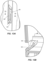
- a scoop-shaped deflector 340 extends downwardly from the exhaust openings 336 to further inhibit the ingress of fluid, dust and debris. ( FIG. 13 ).
- the scoop-shaped deflector 340 terminates at an angled surface 344 that is oriented to direct fluid, dust, and debris away from the exhaust openings 336 when the core drill 10 is used in a vertical drilling orientation.
- the exhaust openings 336 may be arranged and positioned differently. Additionally, the core drill 10 may exhaust air from other locations.
- the fan 304 draws cooling air into the housing 14 through the intake openings along a cooling air path 348 ( FIG. 10 ).
- the air drawn through the air intake openings 328 is routed upwardly by a wall 352. Any fluid that enters the housing 14 through the intake openings 328 will fall to the bottom of the housing 14, where it can exit through one or more drain orifices (not shown).
- the cooling air then flows along a cooling path 356 and over a finned heat sink 360 to cool the PCB 300. After passing over the heat sink 360, the air can enter the motor housing portion 20, cooling the motor 24 before being discharged through the exhaust openings 336.
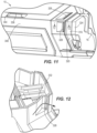
- FIGS. 14-15 illustrate portions of a core drill 410 according to another embodiment.
- the core drill 410 is similar to the core drill 10 described above with reference to FIGS. 1-13B . Accordingly the following description focuses only on differences between the core drill 410 and the core drill 10.
- features and elements of the core drill 410 corresponding with features and elements of the core drill 10 are given like reference numbers plus '400'.
- the core drill 410 includes a drive housing 422 and a handle holder 554 coupled to a mount 550 that extends from a front end of the drive housing 422.
- the handle holder 554 includes an aperture 557 sized and shaped receive the mount 550 such that the handle holder 554 can be slid onto the mount 550.
- the mount 550 and the aperture 557 are cylindrical, but the mount 550 and the aperture 557 may alternatively define other cooperating shapes.
- the handle holder 554 further includes a locking element 559, a nut 561, and a spring 563 disposed between the nut 561 and the locking element 559.
- the locking element 559 includes teeth 565 that project radially inward from an inner periphery of the aperture 557. The teeth 565 are engageable with corresponding teeth or undulations 566 on the mount 550 to retain the handle holder 554 in a particular rotational position on the mount 550.
- the locking element 559 is retractable (ie displaceable toward the nut 561), against the biasing force of the spring 563, to permit the handle holder 554 to rotate about the mount 550 to different rotational positions.
- the core drill 410 includes an auxiliary handle 418 with a threaded shank 574 that is received within the nut 561 to removably couple the auxiliary handle 418 to the handle holder 554.
- a distal end of the threaded shank 574 is engageable with the locking element 559 when the auxiliary handle 418 is rotated relative to the handle holder 554 in a tightening direction 567, which prevents the locking element 559 from retracting.
- the auxiliary handle 418 is thus rotatable in the tightening direction 567 to secure the handle holder 554 (and the auxiliary handle 418) in a particular angular position on the mount 550.
- further rotation of the threaded shank 574 in the tightening direction 567 may exert a clamping force the mount 550 via the locking element 559 to axially secure the handle holder 554 and auxiliary handle 418 on the mount 550.
- the auxiliary handle 418 is rotatable in a loosening direction 569 opposite the tightening direction 567, which, due to the threaded engagement between the shank 574 and the nut 561, displaces the threaded shank 574 away from the locking element 559. If sufficient force is then applied to the auxiliary handle 418, the engagement between the undulations 566 and the teeth 565 causes the locking element 559 to retract into the handle holder 554 and permit rotation of the handle 418 and handle holder 554 about the mount 550. Further rotation of the auxiliary handle 418 in the loosening direction 569 may decouple the handle 418 from the handle holder 554. An operator may then elect to attach the auxiliary handle 418 to other mounting points on the core drill 410 (such as on the mounting portion 178 described above with reference to FIG. 6 ).
- the illustrated core drill 410 includes a bit holder 571 on the spindle 436 and a bit 573 coupled to the bit holder 571.
- the bit holder 571 includes a threaded end portion 575 of the spindle 436 and a backer flange 577 surrounding the spindle 436
- the bit 573 includes internal threads 579 that engage the threaded end portion 575 to couple the bit 573 to the bit holder 571.
- the backer flange 577 has a front portion 581 and a rear portion 583 engaged against a shoulder 585 formed on the spindle.
- the rear portion 583 has an axially-extending wall 587 that at least partially surrounds an outer periphery of the front portion 581.
- a thin disc of low-friction material 589 such as Teflon paper, is disposed axially between the front portion 581 and the rear portion 583 of the backer flange 577.
- the bit 573 In use, to secure the bit 573 to the bit holder 571, an operator engages the threaded portion 575 of the bit holder 571 with the internal threads 579 on the bit 573, then rotates the bit 573 in a tightening direction 591 to advance the bit 573 toward the backer flange 577. Once a rear end 593 of the bit 573 engages the front portion 581 of the backer flange 577, the operator continues to rotate the bit 573 in the tightening direction 591, which develops an axial force on the flange 577 and a corresponding reaction force on the threads 575, 579. This reaction force increases friction between the threads 575, 579 and inhibits the bit 573 from loosening unintentionally.
- the bit 573 includes flats 595 that allow the operator to apply additional torque on the bit 573 in the tightening direction 591 using a wrench, for example.
- the operator rotates the bit 573 in a loosening direction 597.
- the disc of low friction material 589 between the front portion 581 and the rear portion 583 of the backer flange 577 allows the front portion 581 to rotate relative to the rear portion 583 more easily under the axial load applied on the front portion 581 by the bit 573.
- the rear end 593 of the bit 573 does not bind on the backer flange 577, which facilitates removal of the bit 573.
- the bit 573 is an adapter bit.
- the bit 573 includes a second bit holder 599 having a front threaded portion 601.
- the front threaded portion 601 of the second bit holder 599 has a different (e.g, smaller) diameter than the threaded portion 575 of the bit holder 571.
- the core drill 410 is adaptable for use with different tool bits using a single spindle 436.
- the threaded portion 575 of the bit holder 571 may be sized to receive a wet core bit (not shown) intended for use with a fluid distribution system of the core drill 410 (e.g, the fluid distribution system 200).
- the wet core bit may be attached to the bit holder 571 in the same manner as the adapter bit 573 described above.
- the front threaded portion 601 of the second bit holder 599 may be sized to receive a dry core bit (not shown) intended for use without operating the fluid distribution system.
- the second bit holder 599 includes a backer flange 603.
- the backer flange 603 is coupled to the adapter bit 573 by a retaining ring 605.
- a thin disc of low-friction material 607, such as Teflon paper, is disposed axially between the backer flange 603 and a shoulder 608 formed at a base of the front threaded portion 601.
- a bit e.g, the dry core bit
- an operator engages the front threaded portion 601 with internal threads on the bit, then rotates the bit in a tightening direction 591 to advance the bit toward the backer flange 603.
- the operator continues to rotate the bit in the tightening direction 591, which develops an axial force on the flange 603 and a corresponding reaction force on the threads 601. This reaction force increases friction between the threads 601 and the bit, and inhibits the bit from loosening unintentionally.
- the operator rotates the bit in the loosening direction 597.
- the disc of low friction material 607 between the backer flange 603 and the shoulder 608 allows the backer flange 603 to rotate relative to the remainder of the adapter bit 573 more easily under the axial load applied on the front side 609 by the bit. As such, the rear end of the bit does not bind on the backer flange 603, which facilitates removal of the bit.
Abstract
Description
- This application claims priority to co-pending
US Provisional Patent Application No. 62/538,884, filed on July 31, 2017 - The present invention relates to rotary power tools, and more particularly to core drills.
- Core drills are typically used to remove a cylinder of material from a workpiece.
- The present invention provides, in one aspect, a core drill including a housing, a first handle extending from the housing and defining a gap between the handle and the housing, a motor supported within the housing, and a battery removably coupled to the housing and configured to provide power to the motor. The battery has an output voltage greater than 40 volts. The core drill further includes a spindle configured to rotate about a rotational axis in response to torque received from the motor and a fluid delivery system configured to supply fluid to the spindle. The fluid delivery system includes an operable valve to regulate a flow of fluid to the spindle and an auxiliary handle removably coupleable to the housing at each of a first mounting point and a second mounting point.
- The present invention provides, in one aspect, a rotary power tool including a housing having a motor housing portion, a drive housing, and a mounting portion between the motor housing portion and the drive housing. The rotary power tool further includes a motor located within the motor housing portion, a spindle configured to rotate about a rotational axis in response to torque received from the motor, and a band assembly coupled to the drive housing. The band assembly defines a first mounting point, and the mounting portion defines a second mounting point. An auxiliary handle is selectively attachable to each of the first and second mounting points. The first mounting point is located at a first position along the rotational axis, and the second mounting point is located at a second position offset from the first position along the rotational axis.
- The present invention provides, in another aspect, a rotary power tool including a housing, a motor supported within the housing, and a handle extending from the housing and defining a gap between the handle and the housing. A trigger is coupled to the handle and is manipulable to energize the motor. The rotary power tool also includes a spindle configured to rotate about a rotational axis in response to torque received from the motor. The rotary power tool also includes a fluid delivery system configured to supply fluid to the spindle. The fluid delivery system includes an operable valve to regulate a flow of fluid to the spindle. The valve includes an actuator disposed within the gap.
- Other features and aspects of the invention will become apparent by consideration of the following detailed description and accompanying drawings.
-
-
FIG. 1 is a perspective view of a core drill in accordance with an embodiment of the invention. -
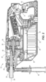
FIG. 2 is a cross-sectional view of the core drill ofFIG. 1 . -
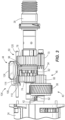
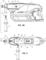
FIG. 3 is a plan view of a drive assembly of the core drill ofFIG. 1 . -
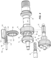
FIG. 4 is a partially exploded view of the drive assembly ofFIG. 3 . -
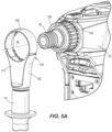
FIG. 5A is a partially exploded view illustrating a band assembly of the core drill ofFIG. 1 . -
FIG. 5B is a partially exploded view illustrating an auxiliary handle of the core drill ofFIG. 1 . -
FIG. 6 is a top view of the core drill ofFIG. 1 illustrating the auxiliary handle in an alternative position. -
FIG. 7 is a perspective view of a portion of the core drill ofFIG. 1 . -
FIG. 8 is a cross-sectional view of a portion of the core drill ofFIG. 1 . -
FIG. 9 is a schematic view illustrating a fluid delivery system of the core drill ofFIG. 1 . -
FIG. 10 is a cross-sectional view illustrating a cooling air path of the core drill ofFIG. 1 . -
FIG. 11 is a perspective view of a portion of the core drill ofFIG. 1 . -
FIG. 12 is a cross-sectional view illustrating an intake opening of the core drill ofFIG. 1 . -
FIG. 13A is a perspective view illustrating an exhaust opening of the core drill ofFIG. 1 . -
FIG. 13B is a cross-sectional view illustrating the exhaust opening ofFIG. 13A . -
FIG. 14 is an exploded view of a front portion of a core drill in accordance with another embodiment of the invention, illustrating a cross-section of an auxiliary handle of the core drill. -
FIG. 15 is a cross-sectional view taken along line 15- 15 inFIG. 14 . - Before any embodiments of the invention are explained in detail, it is to be understood that the invention is not limited in its application to the details of construction and the arrangement of components set forth in the following description or illustrated in the following drawings . The invention is capable of other embodiments and of being practiced or of being carried out in various ways. Also, it is to be understood that the phraseology and terminology used herein is for the purpose of description and should not be regarded as limiting.
-
FIGS. 1 and2 illustrate a rotary power tool, which is acore drill 10 in the illustrated embodiment. Thecore drill 10 includes ahousing 14, a first orrear handle 16, and a second orauxiliary handle 18. A generally D-shaped gap 19 is defined between therear handle 16 and thehousing 14. Thegap 19 provides clearance for a user's fingers when the user grasps therear handle 16. In the illustrated embodiment, therear handle 16 includes abase portion 16a at its lower end that extends to thehousing 14. As such, thegap 19 is an aperture that is fully bounded about its perimeter by therear handle 16, thebase portion 16a, and thehousing 14. In other embodiments, thebase portion 16a may not connect to thehousing 14. - The illustrated
housing 14 is a clamshell housing having left and right cooperatinghalves motor housing portion 20 and a drive housing 22 (FIG. 1 ). Anelectric motor 24 is mounted in the motor housing portion 20 (FIG. 2 ). In the illustrated embodiment, themotor 24 is a brushless direct current motor; however, in other embodiments, thecore drill 10 may include other types of motors. The illustratedcore drill 10 is cordless and includes abattery 28 that provides power to themotor 24. Thebattery 28 is removably coupled to abattery receptacle 30, which is located underneath themotor housing portion 20 in the illustrated embodiment. In other embodiments, thecore drill 10 may be a corded tool configured to receive power from a wall outlet or other remote power source. Atrigger 31 is provided on therear handle 16 and energizes themotor 24 when depressed by a user. - With continued reference to
FIG. 2 , thebattery 28 is a power tool battery pack and includes abattery housing 32 and a plurality ofrechargeable battery cells 34 disposed within thehousing 32. Thebattery cells 34 are preferably lithium-based battery cells but can alternatively have any other suitable chemistry. In the illustrated embodiment, thebattery 28 has a nominal output voltage of about 80V. In other embodiments, thebattery 28 can have a different nominal voltage, such as, for example, 36V, 40V, 72V, between 36V and about 80V, or greater than 40V. - The
core drill 10 further includes aspindle 36 rotatable about arotational axis 38 in response to receiving torque from the motor 24 (FIG. 2 ). A tool bit (not shown) can be coupled to thespindle 36 for co-rotation with thespindle 36 to perform work (e.g, drilling) on a workpiece. Adrive assembly 40 is disposed within thedrive housing 22 to transmit torque from anoutput shaft 42 of themotor 24 to thespindle 36. - With reference to
FIGS. 3 and4 , the illustrateddrive assembly 40 includes amulti-speed transmission 44. Thetransmission 44 includes two gear stages 46, 50 respectively referred to herein as afirst gear stage 46 and asecond gear stage 50; however, the terms first and second do not imply any spatial or mechanical relationship of the gear stages 46, 50 relative to each other, to themotor 24, or to thespindle 36. In the illustrated embodiment of thetransmission 44, thefirst gear stage 46 includes anintermediate shaft 54 and ahelical gear 58 coupled for co-rotation with theintermediate shaft 54. Thehelical gear 58 may be coupled to theintermediate shaft 54 in any of a number of different ways (e.g, by using a key and key way arrangement, an interference fit, a spline-fit, etc.). In the illustrated embodiment, thehelical gear 58 includes an integrated clutch mechanism (not shown) for limiting the amount of torque transferable between themotor 24 and thespindle 36. In other embodiments, other clutch mechanisms may be employed at any position along thedrive assembly 40. Alternatively, themotor 24 may be provided with an electronic clutch, or thedrive assembly 40 may not include a clutch. - The
helical gear 58 includes a plurality of teeth meshed with corresponding teeth on apinion 62 of themotor output shaft 42 for transmitting torque from theoutput shaft 42 to theintermediate shaft 54. In the illustrated embodiment, thehelical gear 58 has a greater number of teeth than thepinion 62 in order to provide a rotational speed reduction and corresponding torque increase frommotor output shaft 42 to theintermediate shaft 54. Thefirst gear stage 46 further includes afirst driving gear 66 and asecond driving gear 70 axially offset from thefirst driving gear 66. The first and second driving gears 66, 70 may be integrally formed with theintermediate shaft 54 or may be formed separately and coupled to theintermediate shaft 54 for co-rotation therewith in any of a number of different ways. - The
second gear stage 50 includes first and second driven gears 74, 78 and ahub 82 supported on thespindle 36 between the driven gears 74, 78. In the illustrated embodiment, thehub 82 is coupled for co-rotation with thespindle 36 using a spline-fit, but thehub 82 may be coupled to thespindle 36 in other ways. The first drivengear 74 and the second drivengear 78 are axially fixed on the spindle 36 (eg, via one or more snap rings, shoulders, or other inter-engaging features) with thehub 82 acting as a spacer between the two drivengears spindle 36 extends through a cylindrical bore in each of the respective drivengears spindle 36. - The first and second driving gears 66, 70 each include external teeth that are continuously meshed with external teeth of respective first and second driven gears 74, 78. In the illustrated embodiment, the
first driving gear 66 and the first drivengear 74 are sized to provide a first gear reduction, and thesecond driving gear 70 and the second drivengear 78 are sized to provide a second gear reduction greater than the first gear reduction. Accordingly, during operation, the first drivengear 74 rotates at a relatively high speed and low torque, and the second drivengear 78 rotates at a relatively low speed and high torque. - Referring to
FIG. 4 , thehub 82 includes a plurality of axially-extendingexternal splines 86. The first drivengear 74 includessplined portion 90 adjacent thehub 82 that has a corresponding plurality of external splines. Similarly, the second drivengear 78 also includes asplined portion 94 adjacent thehub 82 that has a corresponding plurality of external splines. Thetransmission 44 further includes acollar 98 having a plurality ofinternal splines 102 that receive theexternal splines 86 of thehub 82 to couple thecollar 98 for co-rotation with thehub 82. Thehub 82, the driven gears 74, 78, and thecollar 98 can be made of powdered metal using a suitable process, such as a compaction and sintering process. Alternatively, one or more of thehub 82, the driven gears 74, 78, and thecollar 98 can be made of other materials and by other processes, such as machining, die-casting, and the like. As described in further detail below, thecollar 98 is shiftable along thespindle 36 to selectively interconnect thesplines 86 on the hub with thesplined portions gears splines 86 on thehub 82. This difference in width provides clearance to facilitate shifting of the collar. - The
transmission 44 further includes ashift mechanism 104 operable to move thecollar 98 between a first position (not shown), in which thecollar 98 engages thesplined portion 90 of the first drivengear 74 and thehub 82 to couple the first drivengear 74 and thehub 82 for co-rotation, and a second position (FIG. 3 ), in which thecollar 98 engages thesplined portion 94 of the second drivengear 78 and thehub 82 to couple the second drivengear 78 and thehub 82 for co-rotation. In the illustrated embodiment of thetransmission 44, theshift mechanism 104 includes a pair of linearly movable, nestedbrackets collar 98 between the first and second positions. A biasing member 114 (e.g, a coil spring) is disposed between the twobrackets brackets member 114 are movable together along arod 120 in response to manual manipulation of anactuator knob 124. Theactuator knob 124 includes an eccentric pin (not shown) that is received within agap 132 between theshift brackets 106, 110 (FIG. 4 ). As such, rotation of theactuator knob 124 causes linear movement of thebrackets 106, 110 (and therefore, the collar 98). Alternatively, theshift mechanism 104 may be configured in any of a number of different ways for displacing thecollar 98 between the first and second positions. - In operation, when the
transmission 44 is configured in a high speed, low torque mode, theshift mechanism 104 and thecollar 98 are shifted to the first position, thereby coupling the first drivengear 74 to thehub 82 for co- spin. As such, thespindle 36, thehub 82, and the first drivengear 74 all co-rotate together at a relatively high speed. Because the second drivengear 78 is continuously meshed with thesecond driving gear 98, the second drivengear 78 continues to rotate at a relatively slow speed (i.e, slower than the rotational speed of the spindle 22), and thespindle 36 rotates within the second drivengear 78. When thetransmission 44 is configured in a low speed, high torque mode, theshift mechanism 104 and thecollar 98 are shifted to the second position (FIG. 3 ), thereby coupling the second drivengear 78 to thehub 82 for co-rotation. As such, thespindle 22, thehub 82, and the second drivengear 78 all co-rotate together at a relatively low speed. Because the first drivengear 74 remains continuously meshed with thefirst driving gear 94, the first drivengear 74 continues to rotate at a relatively high speed (i.e, faster than the rotational speed of the spindle 22) and rotates relative to thespindle 22. - To shift the
transmission 44 from the high speed, low torque mode to the low speed, high torque mode, a user begins rotating theactuator knob 124. As theactuator knob 124 rotates, the eccentric pin bears against thesecond bracket 110 which, in turn, pushes against the biasingmember 114 to move thefirst bracket 106 and thecollar 98 toward the second position (FIG. 3 ). Thecollar 98 then enters a neutral position (not shown), midway between the first position and the second position. In the neutral position, thecollar 98 is disengaged from both the first and second driven gears 74, 78 such that no torque is transferred from the driven gears 74, 78 to the hub 82 (and therefore, the spindle 36). If the user continues to rotate theactuator knob 124 and theinternal splines 102 of thecollar 98 are not yet aligned with the splines of the second drivengear 78, the biasingmember 114 is compressed between thebrackets member 114 urges thefirst bracket 106 and thecollar 98 into the second position. Accordingly, the biasingmember 114 permits a delay between rotation of theactuator knob 124 and engagement of thecollar 98 with the second drivengear 78. Similarly, when shifting thetransmission 44 from the low speed, high torque mode to the high speed, low torque mode, the biasingmember 114 permits a delay between rotation of theactuator knob 124 and engagement of thecollar 98 with the first drivengear 74. - The
drive assembly 40 of thecore drill 10 advantageously provides for quiet operation. Thecore drill 10 was tested during no-load operation (i.e. without a tool bit coupled to the spindle 36). Sound pressure data was measured using five microphones surrounding thecore drill 10, each positioned at a distance of one meter from thecore drill 10. These measurements were then averaged. In the illustrated embodiment, thecore drill 10 produces an average sound pressure at a distance of one meter from thedrill 10 of 80.0 decibels (dBa) when operating in the high speed, low torque mode. Thecore drill 10 produces an average sound pressure at a distance of one meter from thedrill 10 of 80.4 dBa when operating in the low speed, high torque mode. Thus, regardless of speed, during no-load operation, thecore drill 10 produces an average sound pressure less than 81 dBa at a distance of one meter from thedrill 10. - With reference to
FIG. 5A , thedrive housing 22 includes acylindrical mount 150 extending forward along thespindle 36. A handle holder orband assembly 154 is coupled to themount 150. In the illustrated embodiment, theband assembly 154 includes anadjustable band 158 and a generally Y-shapedbase 162. Theauxiliary handle 18 is removably attached to thebase 162. Theband assembly 154 may be selectively rotatable about therotational axis 38 of thespindle 36 to allow theauxiliary handle 18 to be positioned in a variety of different orientations. In the illustrated embodiment, themount 150 includes a plurality of teeth orundulations 166 that are engageable with corresponding teeth orundulations 170 on the base 162 to define a variety of discrete, angular positions of the band assembly 154 (and the auxiliary handle 18). - With reference to
FIG. 5B , theauxiliary handle 18 includes a threadedshank 174 that is received within a threaded bore (not shown) in the underside of the base 162 to removably couple theauxiliary handle 18 to theband assembly 154. In the illustrated embodiment, thehousing 14 includes a mountingportion 178 situated between thedrive housing 22 and themotor housing portion 20. In some embodiments, the mountingportion 178 may be integrally formed with thedrive housing 22, and in other embodiments, the mountingportion 178 may be integrally formed with themotor housing portion 20. Alternatively, the mountingportion 178 can be a separate component assembled together with thehousing 14. - Referring also to
FIG. 6 , the mountingportion 178 includes a first threaded bore 182 (FIG. 5B ) and a second threaded bore 186 (FIG. 6 ) opposite the first threadedbore 182. Each of thebores shank 174 of theauxiliary handle 18 to directly couple theauxiliary handle 18 to the mountingportion 178. This advantageously provides a variety of different placement options for theauxiliary handle 18. In some embodiments, thecore drill 10 may include only one of the first andsecond bores bores second bores core drill 10, in a direction generally perpendicular to therotational axis 38 of thespindle 36. Accordingly, when theauxiliary handle 18 is attached to thefirst bore 182 or thesecond boron 186, theauxiliary handle 18 extends outwardly from the left side or the right side of thecore drill 10. In other embodiments, one or both of the first andsecond bores rotational axis 38. In some embodiments, the first andsecond bores axis 190 that intersects therotational axis 38. In other embodiments, theaxis 190 can be offset above or below therotational axis 38. In yet other embodiments, the first andsecond bores axis 190 is offset from theband assembly 154 along therotational axis 38 such that theband assembly 154 and thebores auxiliary handle 18 along the length of thecore drill 10. - With reference to
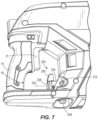
FIGS. 7-9 , the illustratedcore drill 10 further includes afluid distribution system 200. Thefluid distribution system 200 includes afirst connector 204 and a supply line 208 (FIG. 9 ) that can be attached to thefirst connector 204 to provide fluid such as water to thefluid distribution system 200 from an external source (not shown). Adelivery line 212 extends from a second connector 216 (FIG. 7 ) to thespindle 36, and avalve 220 is disposed between the first andsecond connectors supply line 208 to thedelivery line 212. Thedelivery line 212 may extend entirely or partially through the interior of thehousing 14, or may extend entirely or partially along the exterior of thehousing 14. The illustrated first andsecond connectors second connectors housing 14 to provide protection for theconnectors 204 216. - Referring to
FIG. 7 , thevalve 220 includes avalve housing 224, avalve body 228 that is rotatable relative to thevalve housing 224 about anaxis 232, and anactuator lever 236 extending from thevalve body 228. In other embodiments, thevalve 220 may have other components or configurations. Thevalve 220 is positioned proximal therear handle 16 and preferably within thegap 19 between therear handle 16 and thehousing 14. As such, a user may grip therear handle 16, depress thetrigger 31, and actuate the valve 220 (by manipulating the actuator lever 236) with the same hand. In the illustrated embodiment, thevalve 220 is centered along the width of thecore drill 10 such that theaxis 232 is coplanar with therotational axis 38 of thespindle 36. This advantageously allows the user to actuate thevalve 220 regardless of which of the user's hands is used to grasp therear handle 16. In other embodiments, thevalve 220 may be positioned off center, approximate the left side or the right side of thecore drill 10. - With reference to
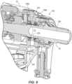
FIG. 8 , the downstream end of thedelivery line 212 can be attached to athird connector 240 located on thedrive housing 22 adjacent theband assembly 154. Thethird connector 240 fluidly communicates with anannular volume 244 surrounding thespindle 36. Theannular volume 244 is bounded by first and second spacedannular seals spindle 36 includes a plurality of radially extendingapertures 252 that fluidly communicate ahollow interior 256 of thespindle 36 with theannular volume 244. As such, fluid that flows through thedelivery line 212 and into theannular volume 244 can enter thespindle 36 through theapertures 252. The fluid can then flow through thehollow interior 256 of thespindle 36, and subsequently through a core bit attached to thespindle 36, for cooling, lubrication, and dust abatement. - Referring to
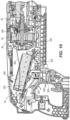
FIG. 10 , operation of themotor 24 is governed by a motor control system including a printed circuit board ("PCB") 300 that includes power electronics such as switching elements and the like. The illustratedcore drill 10 includes afan 304 coupled to themotor output shaft 42 that generates a cooling airflow through thehousing 14 to remove heat from thePCB 300 and/or any other heat-generating components. - The illustrated housing includes left and
right side walls 308, 312 (FIG. 6 ) that extend generally parallel to therotational axis 38 of thespindle 36, and a rear wall 316 (FIG. 11 ) that opposes therear handle 16 Left and rightangled walls 320, 324 extend between therespective side walls rear wall 316, and theangled walls 320, 324 are oriented inward toward the center of thecore drill 10 at an oblique angle. In the illustrated embodiment, theangled walls 320, 324 and therear wall 316 each include a plurality of segments oriented at different angles; however in other embodiments, theangled walls 320, 324 and therear wall 316 may be substantially planar, curved, or include any number of segments or contours. - The
housing 14 includes a plurality ofintake openings 328 located on the angled walls 320, 324 (FIG. 11 ). The position of theintake openings 328 on theangled walls 320, 324 advantageously helps shield them from fluid spray, dust, and debris that may be present during operation of thecore drill 10. In the illustrated embodiment, adeflector 332 is disposed adjacent each of theintake openings 328 to direct fluid away from theopenings 328. In other embodiments, theintake openings 328 may be arranged and positioned differently. Additionally, thecore drill 10 may draw intake air from other locations. - The
housing 14 further includesexhaust openings 336 located on the left andright sides housing 14. Theexhaust openings 336 open downward with reference to the orientation of thecore drill 10 illustrated inFIG. 11 to inhibit fluid, dust, and debris from entering the housing through theexhaust openings 336. A scoop-shapeddeflector 340 extends downwardly from theexhaust openings 336 to further inhibit the ingress of fluid, dust and debris. (FIG. 13 ). The scoop-shapeddeflector 340 terminates at anangled surface 344 that is oriented to direct fluid, dust, and debris away from theexhaust openings 336 when thecore drill 10 is used in a vertical drilling orientation. In other embodiments, theexhaust openings 336 may be arranged and positioned differently. Additionally, thecore drill 10 may exhaust air from other locations. - During operation, the
fan 304 draws cooling air into thehousing 14 through the intake openings along a cooling air path 348 (FIG. 10 ). The air drawn through theair intake openings 328 is routed upwardly by awall 352. Any fluid that enters thehousing 14 through theintake openings 328 will fall to the bottom of thehousing 14, where it can exit through one or more drain orifices ( not shown). The cooling air then flows along acooling path 356 and over afinned heat sink 360 to cool thePCB 300. After passing over theheat sink 360, the air can enter themotor housing portion 20, cooling themotor 24 before being discharged through theexhaust openings 336. -
FIGS. 14-15 illustrate portions of acore drill 410 according to another embodiment. Thecore drill 410 is similar to thecore drill 10 described above with reference toFIGS. 1-13B . Accordingly the following description focuses only on differences between thecore drill 410 and thecore drill 10. In addition, features and elements of thecore drill 410 corresponding with features and elements of thecore drill 10 are given like reference numbers plus '400'. - Referring to
FIG. 14 , thecore drill 410 includes adrive housing 422 and ahandle holder 554 coupled to amount 550 that extends from a front end of thedrive housing 422. Thehandle holder 554 includes anaperture 557 sized and shaped receive themount 550 such that thehandle holder 554 can be slid onto themount 550. In the illustrated embodiment, themount 550 and theaperture 557 are cylindrical, but themount 550 and theaperture 557 may alternatively define other cooperating shapes. - The
handle holder 554 further includes alocking element 559, anut 561, and aspring 563 disposed between thenut 561 and thelocking element 559. The lockingelement 559 includesteeth 565 that project radially inward from an inner periphery of theaperture 557. Theteeth 565 are engageable with corresponding teeth orundulations 566 on themount 550 to retain thehandle holder 554 in a particular rotational position on themount 550. The lockingelement 559 is retractable (ie displaceable toward the nut 561), against the biasing force of thespring 563, to permit thehandle holder 554 to rotate about themount 550 to different rotational positions. - With continued reference to
FIG. 14 , thecore drill 410 includes anauxiliary handle 418 with a threadedshank 574 that is received within thenut 561 to removably couple theauxiliary handle 418 to thehandle holder 554. A distal end of the threadedshank 574 is engageable with the lockingelement 559 when theauxiliary handle 418 is rotated relative to thehandle holder 554 in a tighteningdirection 567, which prevents the lockingelement 559 from retracting. Theauxiliary handle 418 is thus rotatable in the tighteningdirection 567 to secure the handle holder 554 (and the auxiliary handle 418) in a particular angular position on themount 550. In addition, further rotation of the threadedshank 574 in the tighteningdirection 567 may exert a clamping force themount 550 via thelocking element 559 to axially secure thehandle holder 554 andauxiliary handle 418 on themount 550. - Conversely, the
auxiliary handle 418 is rotatable in aloosening direction 569 opposite the tighteningdirection 567, which, due to the threaded engagement between theshank 574 and thenut 561, displaces the threadedshank 574 away from the lockingelement 559. If sufficient force is then applied to theauxiliary handle 418, the engagement between theundulations 566 and theteeth 565 causes thelocking element 559 to retract into thehandle holder 554 and permit rotation of thehandle 418 and handleholder 554 about themount 550. Further rotation of theauxiliary handle 418 in theloosening direction 569 may decouple thehandle 418 from thehandle holder 554. An operator may then elect to attach theauxiliary handle 418 to other mounting points on the core drill 410 (such as on the mountingportion 178 described above with reference toFIG. 6 ). - With reference to
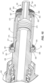
FIG. 15 , the illustratedcore drill 410 includes abit holder 571 on thespindle 436 and abit 573 coupled to thebit holder 571. Thebit holder 571 includes a threadedend portion 575 of thespindle 436 and abacker flange 577 surrounding thespindle 436 Thebit 573 includesinternal threads 579 that engage the threadedend portion 575 to couple thebit 573 to thebit holder 571. Thebacker flange 577 has afront portion 581 and arear portion 583 engaged against ashoulder 585 formed on the spindle. Therear portion 583 has an axially-extendingwall 587 that at least partially surrounds an outer periphery of thefront portion 581. In the illustrated embodiment, a thin disc of low-friction material 589, such as Teflon paper, is disposed axially between thefront portion 581 and therear portion 583 of thebacker flange 577. - In use, to secure the
bit 573 to thebit holder 571, an operator engages the threadedportion 575 of thebit holder 571 with theinternal threads 579 on thebit 573, then rotates thebit 573 in a tighteningdirection 591 to advance thebit 573 toward thebacker flange 577. Once arear end 593 of thebit 573 engages thefront portion 581 of thebacker flange 577, the operator continues to rotate thebit 573 in the tighteningdirection 591, which develops an axial force on theflange 577 and a corresponding reaction force on thethreads threads bit 573 from loosening unintentionally. In the illustrated embodiment, thebit 573 includesflats 595 that allow the operator to apply additional torque on thebit 573 in the tighteningdirection 591 using a wrench, for example. - To loosen the
bit 573, the operator rotates thebit 573 in aloosening direction 597. The disc oflow friction material 589 between thefront portion 581 and therear portion 583 of thebacker flange 577 allows thefront portion 581 to rotate relative to therear portion 583 more easily under the axial load applied on thefront portion 581 by thebit 573. As such, therear end 593 of thebit 573 does not bind on thebacker flange 577, which facilitates removal of thebit 573. - With continued reference to
FIG. 15 , in the illustrated embodiment, thebit 573 is an adapter bit. As such, thebit 573 includes asecond bit holder 599 having a front threadedportion 601. The front threadedportion 601 of thesecond bit holder 599 has a different (e.g, smaller) diameter than the threadedportion 575 of thebit holder 571. Thus, thecore drill 410 is adaptable for use with different tool bits using asingle spindle 436. For example, the threadedportion 575 of thebit holder 571 may be sized to receive a wet core bit (not shown) intended for use with a fluid distribution system of the core drill 410 (e.g, the fluid distribution system 200). The wet core bit may be attached to thebit holder 571 in the same manner as theadapter bit 573 described above. The front threadedportion 601 of thesecond bit holder 599 may be sized to receive a dry core bit (not shown) intended for use without operating the fluid distribution system. - Like the
bit holder 571, thesecond bit holder 599 includes abacker flange 603. Thebacker flange 603 is coupled to theadapter bit 573 by a retainingring 605. A thin disc of low-friction material 607, such as Teflon paper, is disposed axially between thebacker flange 603 and ashoulder 608 formed at a base of the front threadedportion 601. - In use, to secure a bit (e.g, the dry core bit) to the
spindle 436 via thesecond bit holder 599, an operator engages the front threadedportion 601 with internal threads on the bit, then rotates the bit in a tighteningdirection 591 to advance the bit toward thebacker flange 603. Once a rear end of the bit engages afront side 609 of thebacker flange 603, the operator continues to rotate the bit in the tighteningdirection 591, which develops an axial force on theflange 603 and a corresponding reaction force on thethreads 601. This reaction force increases friction between thethreads 601 and the bit, and inhibits the bit from loosening unintentionally. To loosen the bit, the operator rotates the bit in theloosening direction 597. The disc oflow friction material 607 between thebacker flange 603 and theshoulder 608 allows thebacker flange 603 to rotate relative to the remainder of theadapter bit 573 more easily under the axial load applied on thefront side 609 by the bit. As such, the rear end of the bit does not bind on thebacker flange 603, which facilitates removal of the bit. - Various features of the invention are set forth in the following claims.
- Various features of the invention may be defined by the following numbered aspects.
- 1. A core drill comprising: a housing; a first handle extending from the housing and defining a gap between the handle and the housing; a motor supported within the housing; a battery removably coupled to the housing and configured to provide power to the motor, wherein the battery has an output voltage greater than 40 volts; a spindle configured to rotate about a rotational axis in response to torque received from the motor; a fluid delivery system configured to supply fluid to the spindle, the fluid delivery system including a valve operable to regulate a flow of fluid to the spindle; and an auxiliary handle removably coupleable to the housing at each of a first mounting point and a second mounting point.
- 2. The core drill of
aspect 1, wherein the first mounting point is located at a first position along the rotational axis, and the second mounting point is located at a second position offset from the first position along the rotational axis. - 3. The core drill of
aspect 1, wherein the valve includes an actuator disposed within the gap. - 4. The core drill of
aspect 1, wherein the core drill is configured to produce an average sound pressure less than 81 decibels, at a distance of about meter from the housing, during operation of the core drill with no load on the spindle. - 5. The core drill of
aspect 1, wherein the housing includes a motor housing portion in which the motor is received, a drive housing, and a mounting portion between the motor housing portion and the drive housing, wherein the core drill further comprises a handle holder coupled to the drive housing, wherein the handle holder defines the first mounting point, and wherein the handle holder is selectively adjustable relative to the drive housing between a plurality of positions. - 6. The core drill of aspect 5, wherein the mounting portion defines the second mounting point.
- 7. The core drill of aspect 5, further comprising a transmission at least partially disposed within the drive housing and configured to transmit torque from the motor to the spindle, wherein the transmission is shiftable between a high speed mode and a low speed mode.
- 8. The core drill of
aspect 7, wherein the motor includes an output shaft, and wherein the transmission includes an intermediate shaft driven by the output shaft. - 9. The core drill of
aspect 8, in which the transmission includes: a first driving gear fixed to the intermediate shaft, a first driven gear meshed with the first driving gear and rotatably supported on the spindle, a second driving gear fixed to the intermediate shaft, and a second driven gear meshed with the second driving gear and rotatably supported on the spindle, wherein the first driving gear and the first driven gear define a first gear reduction, and wherein the second driving gear and the second driven gear define a second gear reduction different than the first gear reduction. - 10. The core drill of aspect 9, further comprising a hub coupled for co-rotation with the spindle and a collar coupled for co-rotation with the hub, the collar being axially shiftable along the spindle between a first position, in which the collar couples the first driven gear for co-rotation with the hub to define the high speed mode, and a second position, in which the collar couples the second driven gear for co-rotation with the hub to define the low speed mode.
- 11. The core drill of
aspect 10, wherein the hub, the collar, the first driven gear, and the second driven gear are made of powdered metal. - 12. A power tool, comprising: a housing including a motor housing portion, a drive housing, and a mounting portion between the motor housing portion and the drive housing; a motor located within the motor housing portion; a spindle configured to rotate about a rotational axis in response to torque received from the motor; a handle holder coupled to the drive housing, the handle holder defining a first mounting point and the mounting portion defining a second mounting point; and an auxiliary handle selectively attachable to each of the first and second mounting points, wherein the first mounting point is located at a first position along the rotational axis, and the second mounting point is located at a second position offset from the first position along the rotational axis.
- 13. The power tool of
aspect 12, wherein the auxiliary handle includes a threaded shank, and wherein each of the first and second mounting points includes a threaded bore configured to receive the threaded shank. - 14. The power tool of
aspect 12, wherein the handle holder is selectively rotatable relative to the drive housing about the rotational axis between a plurality of rotational positions. - 15. The power tool of
aspect 12, wherein the mounting portion defines a third mounting point opposite the second mounting point, wherein the auxiliary handle is selectively attachable to the third mounting point. - 16. A power tool, comprising: a housing; a motor supported within the housing; a handle extending from the housing and defining a gap between the handle and the housing; a trigger coupled to the handle, the trigger being manipulable to energize the motor; a spindle configured to rotate about a rotational axis in response to torque received from the motor; and a fluid delivery system configured to supply fluid to the spindle, the fluid delivery system including a valve operable to regulate a flow of fluid to the spindle, wherein the valve includes an actuator disposed within the gap.
- 17. The power tool of
aspect 16, wherein the actuator is rotatable about valve axis, and wherein the valve axis is coplanar with the rotational axis of the spindle. - 18. The power tool of
aspect 16, wherein the housing defines an annular volume surrounding the spindle, wherein the spindle includes a radial aperture in communication with the annular volume, and wherein the fluid delivery system is configured to supply fluid into the annular volume. - 19. The power tool of
aspect 16, wherein the fluid delivery system includes a first connector coupled to the handle, the first connector configured for attachment to a fluid supply line, wherein the valve is disposed downstream of the first connector. - 20. The power tool of
aspect 19, further comprising a fluid delivery line extending between the valve and the annular volume, the fluid delivery line disposed at least partially within the housing. - 21. The power tool of
aspect 12, further comprising a bit holder coupled to the spindle, the bit holder including: a backer flange having a front portion engageable with a tool bit and a rear portion opposite the front portion, and a disc of low friction material disposed between the front portion and the rear portion.
Claims (15)
- A power tool (10), comprising:a housing (14);a motor (24) supported within the housing;a handle (16) extending from the housing and defining a gap (19) between the handle and the housing;a trigger (31) coupled to the handle, the trigger being manipulable to energize the motor; anda spindle (36) configured to rotate about a rotational axis (38) in response to torque received from the motor,characterized by:
a fluid delivery system (200) configured to supply fluid to the spindle, the fluid delivery system including a valve (220) operable to regulate a flow of fluid to the spindle, the valve including an actuator (236),wherein the actuator is disposed within the gap, orwherein the actuator is rotatable about a valve axis (232) coplanar with the rotational axis. - The power tool of claim 1, wherein the fluid delivery system includes a first connector (204) configured for attachment to a fluid supply line (208), and wherein the valve (220) is operable to regulate a flow of fluid from the fluid supply line to the spindle.
- The power tool of claim 2, wherein the fluid delivery system includes a delivery line (212) extending from a second connector (216) to a third connector (240).
- The power tool of claim 3, wherein the valve is disposed fluidly between the first connector and the second connector to regulate fluid flow from the fluid supply line to the delivery line.
- The power tool of claim 3 or 4, wherein the third connector fluidly communicates with an annular volume (244) surrounding the spindle.
- The power tool of any of claims 3 to 5, wherein the first connector and the second connector are recessed into the housing.
- The power tool of claim 1 or 2, wherein the housing defines an annular volume surrounding the spindle (244), wherein the spindle includes a radial aperture (252) in communication with the annular volume, and wherein the fluid delivery system is configured to supply fluid into the annular volume.
- The power tool of any preceding claim, further comprising a battery (28) removably coupled to the housing and configured to provide power to the motor, wherein the battery has an output voltage greater than 40 volts.
- The power tool of any preceding claim, wherein the housing includes a side wall (308, 312) extending generally parallel to the rotational axis, a rear wall (316) opposite the handle, and an angled wall (320, 324) extending between the side wall and the rear wall, the angled wall oriented at an oblique angle relative to the rotational axis.
- The power tool of claim 9, further comprising an intake opening (328) located on the angled wall, wherein air is drawn into the housing through the intake opening during operation of the power tool.
- The power tool of claim 10, further comprising a deflector (332) disposed adjacent the intake opening, the deflector configured to direct fluid away from the intake opening.
- The power tool of any of claims 9-11, further comprising an exhaust opening (336) located on the side wall, wherein air is exhausted out of the housing through the exhaust opening during operation of the power tool.
- The power tool of claim 12, further comprising a deflector (340) extending from the exhaust opening to inhibit fluid from entering the housing through the exhaust opening.
- The power tool of any preceding claim, wherein the actuator is disposed on the handle.
- The power tool of any preceding claim,(a) further comprising an auxiliary handle (418) selectively attachable to the housing at each of a first mounting point (154) and a second mounting point (182, 186), wherein the second mounting point is offset from the first mounting point in a direction along the rotational axis;
or(b) wherein the power tool is configured as a core drill.
Applications Claiming Priority (3)
| Application Number | Priority Date | Filing Date | Title |
|---|---|---|---|
| US201762538884P | 2017-07-31 | 2017-07-31 | |
| EP18841646.5A EP3661700B1 (en) | 2017-07-31 | 2018-07-31 | Rotary power tool |
| PCT/US2018/044490 WO2019027954A1 (en) | 2017-07-31 | 2018-07-31 | Rotary power tool |
Related Parent Applications (1)
| Application Number | Title | Priority Date | Filing Date |
|---|---|---|---|
| EP18841646.5A Division EP3661700B1 (en) | 2017-07-31 | 2018-07-31 | Rotary power tool |
Publications (1)
| Publication Number | Publication Date |
|---|---|
| EP4219082A1 true EP4219082A1 (en) | 2023-08-02 |
Family
ID=65138629
Family Applications (2)
| Application Number | Title | Priority Date | Filing Date |
|---|---|---|---|
| EP18841646.5A Active EP3661700B1 (en) | 2017-07-31 | 2018-07-31 | Rotary power tool |
| EP23176165.1A Pending EP4219082A1 (en) | 2017-07-31 | 2018-07-31 | Rotary power tool |
Family Applications Before (1)
| Application Number | Title | Priority Date | Filing Date |
|---|---|---|---|
| EP18841646.5A Active EP3661700B1 (en) | 2017-07-31 | 2018-07-31 | Rotary power tool |
Country Status (5)
| Country | Link |
|---|---|
| US (4) | US10710172B2 (en) |
| EP (2) | EP3661700B1 (en) |
| CN (1) | CN212311932U (en) |
| AU (2) | AU2018102160A4 (en) |
| WO (1) | WO2019027954A1 (en) |
Families Citing this family (5)
| Publication number | Priority date | Publication date | Assignee | Title |
|---|---|---|---|---|
| US11471956B2 (en) * | 2017-04-27 | 2022-10-18 | Forest Research And Management Organization | Tool device and reaction bar |
| AU2018102160A4 (en) * | 2017-07-31 | 2020-03-05 | Milwaukee Electric Tool Corporation | Rotary power tool |
| EP3960342A1 (en) * | 2020-08-26 | 2022-03-02 | Hilti Aktiengesellschaft | A core drilling machine and method for loosening a screw connection between a core drilling machine and a drill bit |
| US11931879B2 (en) | 2021-06-07 | 2024-03-19 | Black & Decker Inc. | Power tool dual-trigger operation |
| US20230158644A1 (en) * | 2021-11-19 | 2023-05-25 | Panasonic Holdings Corporation | Impact tool and method for manufacturing output block |
Citations (5)
| Publication number | Priority date | Publication date | Assignee | Title |
|---|---|---|---|---|
| GB883684A (en) * | 1958-08-29 | 1961-12-06 | Siemens Schuckert Great Britia | Improvements in or relating to portable electric tools |
| EP0941802A2 (en) * | 1998-03-13 | 1999-09-15 | HILTI Aktiengesellschaft | Drilling apparatus |
| WO2008026987A1 (en) * | 2006-09-01 | 2008-03-06 | Husqvarna Aktiebolag | Drilling machine |
| EP2292385A2 (en) * | 2009-09-03 | 2011-03-09 | HILTI Aktiengesellschaft | Hand-held machine tool with a side handle with integrated supply device |
| DE102012010077A1 (en) * | 2012-05-23 | 2013-11-28 | Weka Elektrowerkzeuge E.K. | Two hand-guided working equipment, particularly separation grinder, has front hand gripper that is pivotally arranged at equipment housing around pivot axis aligned parallel to rotational axis of separation tool |
Family Cites Families (107)
| Publication number | Priority date | Publication date | Assignee | Title |
|---|---|---|---|---|
| US1539068A (en) * | 1923-01-29 | 1925-05-26 | Dorn Electric Tool Company Van | Motor hand tool |
| US2545659A (en) * | 1946-05-01 | 1951-03-20 | Aro Equipment Corp | Adjustable handle for tools |
| US2976436A (en) * | 1957-07-12 | 1961-03-21 | Anton Nicholas | Multi-speed drill |
| US3148568A (en) * | 1962-03-16 | 1964-09-15 | Reed Roller Bit Co | Adjustable dead handle |
| AT279999B (en) * | 1967-07-24 | 1970-03-25 | Hilti Ag | Device for the detachable fastening of a handle and an adjustable drilling depth stop on a hand drill, a hammer drill or a similar hand tool |
| US3583383A (en) * | 1968-05-01 | 1971-06-08 | Wheel Trueing Tool Co | Drilling device with coolant supply |
| US3547350A (en) * | 1968-12-16 | 1970-12-15 | Mc Donnell Douglas Corp | Spraying device |
| DE2023913B2 (en) | 1970-05-15 | 1978-11-02 | Hilti Ag, Schaan (Liechtenstein) | Electropneumatic hammer drill |
| DE2930856A1 (en) | 1979-07-30 | 1981-02-19 | Hilti Ag | DEVICE FOR DRILLING STONE |
| US4209069A (en) * | 1974-09-03 | 1980-06-24 | Lockheed Corporation | Drills with chip collectors |
| DE7923500U1 (en) * | 1979-08-17 | 1981-02-19 | Robert Bosch Gmbh, 7000 Stuttgart | ELECTRIC HAND TOOL |
| DE2944275A1 (en) | 1979-11-02 | 1981-05-14 | Hilti AG, 9494 Schaan | MOTORIZED HAND TOOL |
| DE2950816A1 (en) | 1979-12-17 | 1981-06-25 | Hilti AG, 9494 Schaan | TRIPOD DRILL |
| DE3046190A1 (en) | 1980-12-08 | 1982-07-15 | Hilti AG, 9494 Schaan | MILLING TOOL FOR MAKING EXCEPTIONS IN COMPONENTS FROM BRICKWALL, CONCRETE OR OTHER SPRODLE MATERIALS |
| DE3434075A1 (en) | 1984-09-17 | 1986-03-27 | Hilti Ag, Schaan | TRIPOD DRILLING DEVICE WITH GUIDE COLUMN |
| US4730134A (en) | 1987-05-28 | 1988-03-08 | The Singer Company | Portable power tool with combination bearing plate, nut plate and auxiliary handle mount |
| US4820090A (en) * | 1988-06-03 | 1989-04-11 | Chen Pi Chi | Multipurpose handle grip for holding electric tools |
| US5076482A (en) | 1990-10-05 | 1991-12-31 | The Fletcher Terry Company | Pneumatic point driver |
| US5049012A (en) * | 1991-03-11 | 1991-09-17 | Ryobi Motor Products Corp. | Auxiliary handle for hand-held drill |
| DE4234935A1 (en) | 1992-10-16 | 1994-05-05 | Meisner Gmbh Maschbau | Tool stand for holding and moving tools, especially stone drills and saws |
| JP2537968Y2 (en) | 1992-12-10 | 1997-06-04 | 株式会社空研 | Regulator structure in impact wrench |
| DE4444853B4 (en) | 1994-12-16 | 2006-09-28 | Hilti Ag | Hand tool for material-removing machining with an electro-acoustic transducer for the generation of ultrasonic vibrations |
| DE19648868A1 (en) | 1996-11-26 | 1998-05-28 | Hilti Ag | Drilling tool with a hollow cylindrical support body |
| DE29711704U1 (en) | 1997-07-04 | 1997-09-04 | Hilti Ag | Drilling and / or chiseling device |
| DE19740462A1 (en) | 1997-09-15 | 1999-03-18 | Hilti Ag | Drill |
| DE19740464A1 (en) * | 1997-09-15 | 1999-03-18 | Hilti Ag | Drive device for hollow drilling tools |
| DE19810911A1 (en) | 1998-03-13 | 1999-09-16 | Hilti Ag | Drilling tool |
| DE19821554B4 (en) | 1998-05-14 | 2006-02-16 | Hilti Ag | Drill with impact mechanism |
| JP3777796B2 (en) * | 1998-06-12 | 2006-05-24 | 日立工機株式会社 | Electric tool |
| DE19854468A1 (en) * | 1998-11-25 | 2000-06-08 | Flex Elektrowerkzeuge Gmbh | Hand tool |
| DE19905085A1 (en) | 1999-01-29 | 2000-08-03 | Black & Decker Inc N D Ges D S | Battery operated, hand-held power tool |
| JP2001088059A (en) * | 1999-09-17 | 2001-04-03 | Hitachi Koki Co Ltd | Power tool |
| DE10006042B4 (en) * | 2000-02-10 | 2020-01-09 | Robert Bosch Gmbh | Hand tool with depth stop |
| DE10022582A1 (en) | 2000-05-09 | 2001-11-15 | Hilti Ag | Hand tool with suction dust collector |
| DE10025352B4 (en) | 2000-05-23 | 2007-09-20 | Hilti Ag | Tool device with an ultrasonic adapter |
| DE10029728A1 (en) | 2000-06-16 | 2001-12-20 | Hilti Ag | Hand tool |
| DE10043418A1 (en) | 2000-09-04 | 2002-04-18 | Hilti Ag | Cooling and rinsing device for tools for processing rock |
| DE10058587A1 (en) | 2000-11-25 | 2002-05-29 | Hilti Ag | Rotary machine tool, especially drill, has two sets of grooves in its insertion region for receiving male members of tool mounting |
| DE10102308A1 (en) | 2001-01-19 | 2002-07-25 | Hilti Ag | Rotary-percussive rockdrill with flushing bore uses symmetrically placed driver grooves larger than residual web round smooth cylindrical shaft for increased torque and percussion rate. |
| DE10112364A1 (en) | 2001-03-15 | 2002-09-19 | Hilti Ag | Hand tool with electronic depth stop |
| DE10119562A1 (en) | 2001-04-21 | 2002-10-24 | Hilti Ag | Impact drilling tool for rock |
| SE524524C2 (en) * | 2001-11-26 | 2004-08-24 | Atlas Copco Tools Ab | Pneumatic power tool with drain air deflector |
| US6595300B2 (en) | 2001-12-20 | 2003-07-22 | Black & Decker Inc. | Side handles on drill/drivers |
| DE10226866A1 (en) | 2002-06-17 | 2004-01-08 | Hilti Ag | Drill stand for a portable core drilling machine |
| DE10231878A1 (en) | 2002-07-12 | 2004-01-22 | Hilti Ag | Drill stand for a core drilling machine |
| DE10233365B4 (en) | 2002-07-23 | 2016-08-18 | Hilti Aktiengesellschaft | Tool holder for a core bit |
| CN2576386Y (en) * | 2002-11-19 | 2003-10-01 | 南京泉峰国际贸易有限公司 | Secondary handle with laser positioning measuring-scale used on drilling tools |
| US7589500B2 (en) * | 2002-11-22 | 2009-09-15 | Milwaukee Electric Tool Corporation | Method and system for battery protection |
| DE10256043A1 (en) | 2002-11-30 | 2004-06-09 | Hilti Ag | Tool holder for core bits |
| DE10256050A1 (en) | 2002-11-30 | 2004-06-09 | Hilti Ag | Tool holder for core bits |
| DE10303008A1 (en) | 2003-01-27 | 2004-08-05 | Hilti Ag | Guide rail system for a machine tool |
| DE10304405B4 (en) | 2003-02-01 | 2012-10-04 | Hilti Aktiengesellschaft | Method for controlling a core drilling machine |
| US20040163214A1 (en) * | 2003-02-25 | 2004-08-26 | Motomax Electric Co., Ltd. | Assist handle for electric tools |
| US6729415B1 (en) | 2003-04-18 | 2004-05-04 | Techway Industrial Co., Ltd. | Portable electric tool with bi-directionally mountable battery holder |
| USD559059S1 (en) * | 2004-01-13 | 2008-01-08 | Black & Decker Inc. | Drill |
| US7926187B2 (en) | 2004-02-20 | 2011-04-19 | Milwaukee Electric Tool Corporation | Band saw |
| WO2005102626A2 (en) | 2004-04-15 | 2005-11-03 | Milwaukee Electric Tool Corporation | Saw, such as a miter saw |
| ATE396838T1 (en) | 2004-12-23 | 2008-06-15 | Black & Decker Inc | POWER TOOL HOUSING |
| EP1674743B1 (en) | 2004-12-23 | 2014-01-22 | Black & Decker Inc. | Drive mechanism for a power tool |
| EP1674207B1 (en) | 2004-12-23 | 2008-12-10 | BLACK & DECKER INC. | Power tool |
| EP1674205B1 (en) | 2004-12-23 | 2014-03-19 | Black & Decker Inc. | Drive mechanism for power tool |
| EP1674211A1 (en) | 2004-12-23 | 2006-06-28 | BLACK & DECKER INC. | Power tool housing |
| EP1674213B1 (en) | 2004-12-23 | 2008-10-01 | BLACK & DECKER INC. | Power tool cooling |
| CN2762964Y (en) * | 2005-01-10 | 2006-03-08 | 南京德朔实业有限公司 | Electric tool power supplied by battery |
| DE102005000027A1 (en) | 2005-04-06 | 2006-10-12 | Hilti Ag | Clamping device for axially harmoniously oscillating components |
| JP2009541068A (en) * | 2006-06-19 | 2009-11-26 | ディメイン テクノロジー プロプライエタリー リミテッド | Power tool and chuck release device |
| DE102006041069A1 (en) * | 2006-09-01 | 2008-03-06 | Robert Bosch Gmbh | Auxiliary handle device |
| DE102006035345A1 (en) | 2006-10-12 | 2008-04-17 | Hilti Ag | Mobile fluid delivery device for a tool device |
| WO2008089384A2 (en) | 2007-01-18 | 2008-07-24 | Diamond Products, Limited | Portable concrete boring machine |
| US7980793B2 (en) * | 2007-03-23 | 2011-07-19 | The Boeing Company | Concentric clamping for drill spindles |
| US7824247B1 (en) * | 2007-06-01 | 2010-11-02 | The United States Of America As Represented By The Administrator Of The National Aeronautics And Space Administration | Portable rapid and quiet drill |
| US9776296B2 (en) * | 2008-05-09 | 2017-10-03 | Milwaukee Electric Tool Corporation | Power tool dust collector |
| DE102008042846A1 (en) | 2008-10-15 | 2010-06-02 | Hilti Aktiengesellschaft | Drilling device and drilling method |
| US8690497B2 (en) | 2008-10-30 | 2014-04-08 | Black & Decker Inc. | Handle and attachments for right angle drill |
| DE102009022088A1 (en) * | 2009-05-20 | 2010-11-25 | Friedrich Duss Maschinenfabrik Gmbh & Co.Kg | Electric power tool, in particular hand-operated hammer drill |
| JP5479023B2 (en) | 2009-10-20 | 2014-04-23 | 株式会社マキタ | Rechargeable power tool |
| DE202009018606U1 (en) | 2009-12-18 | 2012-04-13 | Hilti Aktiengesellschaft | Device for processing a cooling and rinsing liquid |
| WO2011129733A1 (en) | 2010-04-16 | 2011-10-20 | Husqvarna Ab | A drilling device with a controller for the feeding unit. |
| WO2011129731A1 (en) * | 2010-04-16 | 2011-10-20 | Husqvarna Ab | A core drilling machine and a handle assembly for a core drilling machine. |
| DE102010028241A1 (en) * | 2010-04-27 | 2011-10-27 | Robert Bosch Gmbh | Minimum quantity lubrication system |
| DE102010028302A1 (en) | 2010-04-28 | 2011-12-01 | Hilti Aktiengesellschaft | drilling |
| JP5657436B2 (en) | 2011-03-16 | 2015-01-21 | 株式会社マキタ | Work tools |
| DE102011005903A1 (en) | 2011-03-22 | 2012-09-27 | Hilti Aktiengesellschaft | Drill bit removal tool from hammer drill bits |
| DE102011006015A1 (en) | 2011-03-24 | 2012-09-27 | Hilti Aktiengesellschaft | Tapping System |
| DE102011006369A1 (en) | 2011-03-29 | 2012-10-04 | Hilti Aktiengesellschaft | Electric power tool with electronic cooling |
| US8800412B2 (en) * | 2011-08-19 | 2014-08-12 | Snap-On Incorporated | Auxiliary power tool handle |
| US9114492B2 (en) * | 2011-10-07 | 2015-08-25 | Ahhneu-Ellsworth Limited Liability | Coolant supply for a machine tool |
| DE102011085772A1 (en) | 2011-11-04 | 2013-05-08 | Hilti Aktiengesellschaft | Process for residue-free removal of mineral building materials and machine tool |
| DE102012204491A1 (en) | 2012-03-21 | 2013-09-26 | Hilti Aktiengesellschaft | drilling |
| RU2014153868A (en) | 2012-06-12 | 2016-07-27 | Хускварна Аб | ELECTRIC CUTTING SYSTEM |
| DE102013205827A1 (en) | 2013-04-03 | 2014-10-09 | Hilti Aktiengesellschaft | feeder |
| EP2826609A1 (en) | 2013-07-18 | 2015-01-21 | HILTI Aktiengesellschaft | Automatic drilling aid |
| EP2835198A1 (en) | 2013-08-09 | 2015-02-11 | HILTI Aktiengesellschaft | Intuitive, adaptive spot drilling function |
| US9434038B2 (en) * | 2013-11-01 | 2016-09-06 | Milwaukee Electric Tool Corporation | Shifting mechanism for a drill press |
| CN103956441A (en) | 2013-11-12 | 2014-07-30 | 常州格力博有限公司 | Battery pack and electric tool using the same |
| JP6334144B2 (en) * | 2013-11-26 | 2018-05-30 | 株式会社マキタ | Reciprocating work tool |
| EP2915633A1 (en) | 2014-03-07 | 2015-09-09 | HILTI Aktiengesellschaft | Adaptive power indicator |
| EP2923802A1 (en) | 2014-03-25 | 2015-09-30 | HILTI Aktiengesellschaft | Belt cooling |
| DE102014211046A1 (en) | 2014-06-10 | 2015-12-17 | Robert Bosch Gmbh | System comprising at least one electronically commutated electric motor of a defined size and a rechargeable battery of at least one voltage class |
| DE102014215045A1 (en) | 2014-07-31 | 2016-02-04 | Robert Bosch Gmbh | High-performance portable power tool |
| EP4071907A1 (en) * | 2015-06-05 | 2022-10-12 | Milwaukee Electric Tool Corporation | Support member for battery pack top housing |
| CN204711263U (en) | 2015-06-17 | 2015-10-21 | 大秦铁路股份有限公司朔州工务段 | Portable charged lithium battery rail bonding drill |
| EP3162513B1 (en) | 2015-10-30 | 2019-04-17 | Black & Decker Inc. | High power brushless motor |
| US10950912B2 (en) * | 2017-06-14 | 2021-03-16 | Milwaukee Electric Tool Corporation | Arrangements for inhibiting intrusion into battery pack electrical components |
| TWM575626U (en) * | 2017-06-26 | 2019-03-11 | 美商米沃奇電子工具公司 | battery charger |
| TWM578899U (en) * | 2017-06-30 | 2019-06-01 | 美商米沃奇電子工具公司 | Electrical combination, power tool system, electric motor assembly, electric motor, battery pack and motor assembly |
| AU2018102160A4 (en) * | 2017-07-31 | 2020-03-05 | Milwaukee Electric Tool Corporation | Rotary power tool |
-
2018
- 2018-07-31 AU AU2018102160A patent/AU2018102160A4/en not_active Ceased
- 2018-07-31 WO PCT/US2018/044490 patent/WO2019027954A1/en unknown
- 2018-07-31 EP EP18841646.5A patent/EP3661700B1/en active Active
- 2018-07-31 AU AU2018312343A patent/AU2018312343A1/en active Pending
- 2018-07-31 US US16/050,044 patent/US10710172B2/en active Active
- 2018-07-31 CN CN201890001083.8U patent/CN212311932U/en active Active
- 2018-07-31 EP EP23176165.1A patent/EP4219082A1/en active Pending
-
2019
- 2019-12-11 US US16/710,154 patent/US11185932B2/en active Active
- 2019-12-11 US US16/710,157 patent/US10828705B2/en active Active
-
2021
- 2021-11-29 US US17/536,210 patent/US20220080513A1/en active Pending
Patent Citations (5)
| Publication number | Priority date | Publication date | Assignee | Title |
|---|---|---|---|---|
| GB883684A (en) * | 1958-08-29 | 1961-12-06 | Siemens Schuckert Great Britia | Improvements in or relating to portable electric tools |
| EP0941802A2 (en) * | 1998-03-13 | 1999-09-15 | HILTI Aktiengesellschaft | Drilling apparatus |
| WO2008026987A1 (en) * | 2006-09-01 | 2008-03-06 | Husqvarna Aktiebolag | Drilling machine |
| EP2292385A2 (en) * | 2009-09-03 | 2011-03-09 | HILTI Aktiengesellschaft | Hand-held machine tool with a side handle with integrated supply device |
| DE102012010077A1 (en) * | 2012-05-23 | 2013-11-28 | Weka Elektrowerkzeuge E.K. | Two hand-guided working equipment, particularly separation grinder, has front hand gripper that is pivotally arranged at equipment housing around pivot axis aligned parallel to rotational axis of separation tool |
Also Published As
| Publication number | Publication date |
|---|---|
| US10828705B2 (en) | 2020-11-10 |
| WO2019027954A1 (en) | 2019-02-07 |
| US10710172B2 (en) | 2020-07-14 |
| CN212311932U (en) | 2021-01-08 |
| AU2018102160A4 (en) | 2020-03-05 |
| EP3661700A4 (en) | 2021-05-19 |
| US20200108454A1 (en) | 2020-04-09 |
| EP3661700A1 (en) | 2020-06-10 |
| US20200108453A1 (en) | 2020-04-09 |
| AU2018312343A1 (en) | 2020-02-13 |
| US20220080513A1 (en) | 2022-03-17 |
| US11185932B2 (en) | 2021-11-30 |
| EP3661700B1 (en) | 2023-05-31 |
| US20190030622A1 (en) | 2019-01-31 |
Similar Documents
| Publication | Publication Date | Title |
|---|---|---|
| US10828705B2 (en) | Rotary power tool | |
| CN102335895B (en) | Power tool having circuit board | |
| EP3326742B1 (en) | Power tool with a dust collecting device | |
| US6461088B2 (en) | Two speed right angle drill | |
| EP2181786B1 (en) | Handheld power tool | |
| US7225707B2 (en) | Torque wrench with quick-release gear set | |
| EP2156537B1 (en) | Electric motor comprising a receiving element | |
| US10596693B2 (en) | Power tool with detachable auxiliary handle | |
| US20100126029A1 (en) | Reconfigurable portable powered tool and method of reconfiguring such a tool | |
| EP2433728A2 (en) | Chuck with an indicator mechanism | |
| US20230201936A1 (en) | Band saw | |
| US7677281B2 (en) | Power router tool | |
| US9149876B2 (en) | Core drilling machine and a handle assembly for a core drilling machine | |
| US10513023B2 (en) | Power tool | |
| JP2009090434A (en) | Motor-driven drill | |
| CN102581377B (en) | Reciprocating cutting tool | |
| US20030085534A1 (en) | Quick attachment release system for a rotary hand tool | |
| CN102581378B (en) | Cutting tool | |
| US6698533B2 (en) | Portable power tool with grease lubricated angle drive | |
| JP2020069587A (en) | Electric apparatus | |
| US20240051084A1 (en) | Die grinder with an offset gear transmission | |
| WO2023091498A1 (en) | Attachment mechanism for a power tool |
Legal Events
| Date | Code | Title | Description |
|---|---|---|---|
| PUAI | Public reference made under article 153(3) epc to a published international application that has entered the european phase |
Free format text: ORIGINAL CODE: 0009012 |
|
| STAA | Information on the status of an ep patent application or granted ep patent |
Free format text: STATUS: THE APPLICATION HAS BEEN PUBLISHED |
|
| AC | Divisional application: reference to earlier application |
Ref document number: 3661700 Country of ref document: EP Kind code of ref document: P |
|
| AK | Designated contracting states |
Kind code of ref document: A1 Designated state(s): AL AT BE BG CH CY CZ DE DK EE ES FI FR GB GR HR HU IE IS IT LI LT LU LV MC MK MT NL NO PL PT RO RS SE SI SK SM TR |
|
| RIN1 | Information on inventor provided before grant (corrected) |
Inventor name: EICHE, PAUL, W. Inventor name: TIMMONS, TERRY, L. Inventor name: CARLSON, MITCHELL |
|
| STAA | Information on the status of an ep patent application or granted ep patent |
Free format text: STATUS: REQUEST FOR EXAMINATION WAS MADE |
|
| 17P | Request for examination filed |
Effective date: 20240201 |
|
| RBV | Designated contracting states (corrected) |
Designated state(s): AL AT BE BG CH CY CZ DE DK EE ES FI FR GB GR HR HU IE IS IT LI LT LU LV MC MK MT NL NO PL PT RO RS SE SI SK SM TR |