EP0941802A2 - Drilling apparatus - Google Patents
Drilling apparatus Download PDFInfo
- Publication number
- EP0941802A2 EP0941802A2 EP99810125A EP99810125A EP0941802A2 EP 0941802 A2 EP0941802 A2 EP 0941802A2 EP 99810125 A EP99810125 A EP 99810125A EP 99810125 A EP99810125 A EP 99810125A EP 0941802 A2 EP0941802 A2 EP 0941802A2
- Authority
- EP
- European Patent Office
- Prior art keywords
- valve
- coolant
- drilling device
- drilling
- line
- Prior art date
- Legal status (The legal status is an assumption and is not a legal conclusion. Google has not performed a legal analysis and makes no representation as to the accuracy of the status listed.)
- Granted
Links
Images
Classifications
-
- B—PERFORMING OPERATIONS; TRANSPORTING
- B28—WORKING CEMENT, CLAY, OR STONE
- B28D—WORKING STONE OR STONE-LIKE MATERIALS
- B28D1/00—Working stone or stone-like materials, e.g. brick, concrete or glass, not provided for elsewhere; Machines, devices, tools therefor
- B28D1/02—Working stone or stone-like materials, e.g. brick, concrete or glass, not provided for elsewhere; Machines, devices, tools therefor by sawing
- B28D1/04—Working stone or stone-like materials, e.g. brick, concrete or glass, not provided for elsewhere; Machines, devices, tools therefor by sawing with circular or cylindrical saw-blades or saw-discs
- B28D1/041—Working stone or stone-like materials, e.g. brick, concrete or glass, not provided for elsewhere; Machines, devices, tools therefor by sawing with circular or cylindrical saw-blades or saw-discs with cylinder saws, e.g. trepanning; saw cylinders, e.g. having their cutting rim equipped with abrasive particles
-
- B—PERFORMING OPERATIONS; TRANSPORTING
- B23—MACHINE TOOLS; METAL-WORKING NOT OTHERWISE PROVIDED FOR
- B23Q—DETAILS, COMPONENTS, OR ACCESSORIES FOR MACHINE TOOLS, e.g. ARRANGEMENTS FOR COPYING OR CONTROLLING; MACHINE TOOLS IN GENERAL CHARACTERISED BY THE CONSTRUCTION OF PARTICULAR DETAILS OR COMPONENTS; COMBINATIONS OR ASSOCIATIONS OF METAL-WORKING MACHINES, NOT DIRECTED TO A PARTICULAR RESULT
- B23Q11/00—Accessories fitted to machine tools for keeping tools or parts of the machine in good working condition or for cooling work; Safety devices specially combined with or arranged in, or specially adapted for use in connection with, machine tools
- B23Q11/10—Arrangements for cooling or lubricating tools or work
- B23Q11/1015—Arrangements for cooling or lubricating tools or work by supplying a cutting liquid through the spindle
-
- B—PERFORMING OPERATIONS; TRANSPORTING
- B28—WORKING CEMENT, CLAY, OR STONE
- B28D—WORKING STONE OR STONE-LIKE MATERIALS
- B28D7/00—Accessories specially adapted for use with machines or devices of the preceding groups
- B28D7/02—Accessories specially adapted for use with machines or devices of the preceding groups for removing or laying dust, e.g. by spraying liquids; for cooling work
-
- Y—GENERAL TAGGING OF NEW TECHNOLOGICAL DEVELOPMENTS; GENERAL TAGGING OF CROSS-SECTIONAL TECHNOLOGIES SPANNING OVER SEVERAL SECTIONS OF THE IPC; TECHNICAL SUBJECTS COVERED BY FORMER USPC CROSS-REFERENCE ART COLLECTIONS [XRACs] AND DIGESTS
- Y10—TECHNICAL SUBJECTS COVERED BY FORMER USPC
- Y10T—TECHNICAL SUBJECTS COVERED BY FORMER US CLASSIFICATION
- Y10T408/00—Cutting by use of rotating axially moving tool
- Y10T408/44—Cutting by use of rotating axially moving tool with means to apply transient, fluent medium to work or product
- Y10T408/45—Cutting by use of rotating axially moving tool with means to apply transient, fluent medium to work or product including Tool with duct
Definitions
- the invention relates to a drilling device with a coolant line for coolant according to the Preamble of claim 1.
- a drilling device is known from DE-GM 8 200 668, which cooperates with a coolant line for supplying coolant, which in the Area of a tool holder opens into the interior of the housing of the drilling device, from where the coolant into the interior of a tubular support body of a drilling tool reached.
- the coolant line is connected to a pump that is in one Coolant reservoir is arranged and to promote a corresponding to the performance of the pump Amount of coolant switched on separately before each drilling operation and must be switched off separately after each drilling operation.
- the invention has for its object to provide a drill with which Coolant is supplied in a simple and safe manner and also that of The amount of coolant supplied to the processing point can be adjusted as required.
- the first valve can be supplied from an external reservoir, for example Interrupt coolant supply under pressure quickly and safely.
- the coolant line expediently interacts with a second valve, the is arranged in series with the first valve and has a second outlet channel, whose cross section is partially reducible. This makes it possible for the drilling tool change the amount of coolant supplied.
- the first valve is advantageously in the feed direction of the coolant upstream of the second valve.
- the cross section is preferably reduced the clear width of the first and the second outlet channel of the valves one displaceable actuator each.
- the actuator of the second valve can be moved, independently whether the drill is in operation is expediently the actuator of the second valve can be moved by means of a manually operated adjusting screw.
- the actuator of the first valve can be displaced by means of an electrical magnetic switch.
- the magnetic switch is preferably controlled via an operating switch of the drill.
- the supply of the coolant can be controlled by preferably the coolant line communicates with a sight glass which is the second valve in the feed direction of the Coolant is connected downstream.
- part of the coolant line is advantageously in a Mounting plate arranged to accommodate the two valves and the sight glass serves.
- a pressure compensation device can also be used with the coolant line, for example interact with the help of which the pressure of the coolant is constant and appropriate for the application can be maintained, a non-constant coolant line pressure compensated becomes.
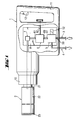
- the drill shown in FIG. 1 has a housing 1, a handle 11, a Actuation switch 12, a rotatably mounted tool holder 10, one in the tool holder 10 clamped drilling tool 2, a coolant line 3 and a Coolant discharge line 4.
- the coolant line 3 acts with a first and a second valve 5, 6 and a sight glass 7 together.
- the coolant line 3 opens in the area of the sight glass 7 into the interior of the housing 1 and from there via the central area of the tool holder 10 into the interior of the drilling tool 2.
- This Drilling tool 2 is composed of an insertion end 21, a tubular one Carrier body 22 and an annular cutting area 23.
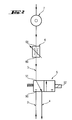
- the first and the second valve 5, 6 each have an inlet channel 50, 60 and an outlet channel 51, 61 each.
- the first valve 5 is in the feed direction of the coolant upstream of the second valve 6 in series.
- the first valve 5 has an displaceable actuator with which the cross section of the clear width of the outlet channel 51 can be reduced to zero.
- the displacement of the actuator is used Solenoid valve 52.
- the first valve 5 is connected to a coolant discharge line 4, which in the actuated position of the first valve 5 between a first Inlet channel 50 of the first valve 5 and the drilling tool 2 part of the coolant line 3 connects to the coolant discharge line 4.
- the second valve 6 has a displaceable actuator with which the cross section of the clear width of the outlet channel 61 can be reduced.
- the displacement of the actuator serves a manually operated adjusting screw 62.
- the first valve 5 is, for example, as 3/2 way valve designed.
- a part of the coolant line 3 is arranged in a mounting plate 8, that of the receptacle the two valves 5, 6 and the sight glass 7 is used.
Abstract
Description
Die Erfindung betrifft ein Bohrgerät mit einer Kühlmittelleitung für Kühlmittel gemäss dem
Oberbegriff des Patentanspruchs 1.The invention relates to a drilling device with a coolant line for coolant according to the
Preamble of
Bei der Herstellung von Bohrungen in einem harten Untergrund wie Beton, Gestein, Stahl oder dergleichen ist es notwendig, der Bearbeitungsstelle eine grosse Menge an Kühlmittel zum Kühlen des Bohrwerkzeuges und zum Abtransport des Bohrkleins zuzuführen. So ist beispielsweise aus dem DE-GM 8 200 668 ein Bohrgerät bekannt, das zum Zuführen von Kühlmittel mit einer Kühlmittel leitung zusammenwirkt, die im Bereich eines Werkzeughalters in das Innere des Gehäuses des Bohrgerätes mündet, von wo das Kühlmittel in das Innere eines rohrförmigen Trägerkörpers eines Bohrwerkzeuges gelangt. Die Kühlmittelleitung steht mit einer Pumpe in Verbindung, die in einem Kühlmittelreservoir angeordnet ist und zur Förderung einer der Leistung der Pumpe entsprechenden Menge Kühlmittel vor jeder Bohroperation gesondert eingeschaltet und nach jeder Bohroperation wieder gesondert ausgeschaltet werden muss.When drilling holes in a hard surface such as concrete, stone, Steel or the like, it is necessary to the machining site a large amount Coolant for cooling the drilling tool and for removing the cuttings feed. For example, a drilling device is known from DE-GM 8 200 668, which cooperates with a coolant line for supplying coolant, which in the Area of a tool holder opens into the interior of the housing of the drilling device, from where the coolant into the interior of a tubular support body of a drilling tool reached. The coolant line is connected to a pump that is in one Coolant reservoir is arranged and to promote a corresponding to the performance of the pump Amount of coolant switched on separately before each drilling operation and must be switched off separately after each drilling operation.
Der Erfindung liegt die Aufgabe zugrunde, ein Bohrgerät zu schaffen, mit dem das Zuführen von Kühlmittel in einfacher und sicherer Weise erfolgt und zudem die der Bearbeitungsstelle zugeführte Kühlmittelmenge bedarfsgerecht einstellbar ist.The invention has for its object to provide a drill with which Coolant is supplied in a simple and safe manner and also that of The amount of coolant supplied to the processing point can be adjusted as required.
Die Lösung dieser Aufgabe erfolgt durch ein Bohrgerät, welches die im kennzeichnenden
Abschnitt des Patentanspruchs 1 angeführten Merkmale aufweist. Mit Hilfe
des ersten Ventils lässt sich die Zufuhr des beispielsweise von einem externen Reservoir
unter Druck zugeführten Kühlmittels schnell und sicher unterbrechen.This task is solved by a drilling rig, which is characteristic of the
Section of
Zweckmässigerweise wirkt die Kühlmittelleitung mit einem zweiten Ventil zusammen, das zum ersten Ventil in Serie angeordnet ist und einen zweiten Auslasskanal aufweist, dessen Querschnitt teilweise reduzierbar ist. Dadurch ist es möglich, die dem Bohrwerkzeug zugeführte Menge an Kühlmittel zu verändern. The coolant line expediently interacts with a second valve, the is arranged in series with the first valve and has a second outlet channel, whose cross section is partially reducible. This makes it possible for the drilling tool change the amount of coolant supplied.
Damit das zweite Ventil druckfrei gehalten werden kann, wenn sich das Bohrgerät nicht in Betrieb befindet, ist vorteilhafterweise das erste Ventil in Zuführrichtung des Kühlmittels dem zweiten Ventil vorgeschaltet.So that the second valve can be kept pressure-free when the drill is not is in operation, the first valve is advantageously in the feed direction of the coolant upstream of the second valve.
Aus handhabungstechnischen Gründen erfolgt vorzugsweise die Reduzierung des Querschnitts der lichten Weite des ersten und des zweiten Auslasskanals der Ventile mittels jeweils eines versetzbaren Stellgliedes.For handling reasons, the cross section is preferably reduced the clear width of the first and the second outlet channel of the valves one displaceable actuator each.
Damit eine Versetzung des Stellgliedes des zweiten Ventils erfolgen kann, unabhängig davon, ob sich das Bohrgerät in Betrieb befindet, ist zweckmässigerweise das Stellglied des zweiten Ventils mittels einer manuell betätigbaren Stellschraube versetzbar.So that the actuator of the second valve can be moved, independently whether the drill is in operation is expediently the actuator of the second valve can be moved by means of a manually operated adjusting screw.
Aus Gründen einer leichten und einfachen Betätigung des ersten Ventils ist vorzugsweise das Stellglied des ersten Ventils mittels eines elektrischen Magnetschalters versetzbar.It is preferred for easy and simple actuation of the first valve the actuator of the first valve can be displaced by means of an electrical magnetic switch.
Um gleichzeitig mit der Inbetriebnahme des Bohrgerätes Kühlmittel der Bearbeitungsstelle zuführen zu können, erfolgt vorzugsweise die Steuerung des Magnetschalters über einen Betätigungsschalter des Bohrgerätes.To cool the machining center simultaneously with the commissioning of the drilling rig To be able to supply, the magnetic switch is preferably controlled via an operating switch of the drill.
Damit nach Abschluss eines Überkopfbohrvorganges das im Innern des Bohrwerkzeuges angesammelte Kühlmittel zurück in das Kühlmittelreservoir gelangen kann, wirkt das Bohrgerät vorteilhafterweise mit einer Kühlmittelabfuhrleitung und einem Unterbrechungsglied zusammen, das bei nicht aktiviertem Betätigungsschalter den zwischen dem Bohrwerkzeug und dem ersten Ventil liegenden Teil der Kühlmittelleitung mit der Kühlmittelabfuhrleitung verbindet.This means that after the completion of an overhead drilling process, this is inside the drilling tool accumulated coolant can get back into the coolant reservoir, acts the drill advantageously with a coolant discharge line and an interrupter together, the between the the drilling tool and the first valve part of the coolant line with the Coolant discharge line connects.
Das Zuführen des Kühlmittels ist kontrollierbar indem vorzugsweise die Kühlmittelleitung mit einem Schauglas in Verbindung steht, das dem zweiten Ventil in Zuführrichtung des Kühlmittels nachgeschaltet ist.The supply of the coolant can be controlled by preferably the coolant line communicates with a sight glass which is the second valve in the feed direction of the Coolant is connected downstream.
Damit die beiden Ventile und das Schauglas montagefreundlich im Bohrgerät aufgenommen werden können, ist vorteilhafterweise ein Teil der Kühlmittelleitung in einer Montageplatte angeordnet, die der Aufnahme der beiden Ventile und des Schauglases dient. So that the two valves and the sight glass are easily installed in the drill can be, part of the coolant line is advantageously in a Mounting plate arranged to accommodate the two valves and the sight glass serves.
Mit der Kühlmittelleitung kann beispielsweise auch eine Druckausgleicheinrichtung zusammenwirken, mit deren Hilfe der Druck des Kühlmittels konstant und anwendungsgerecht gehalten werden kann, ein nicht konstanter Kühlmittelleitungsdruck ausgeglichen wird.A pressure compensation device can also be used with the coolant line, for example interact with the help of which the pressure of the coolant is constant and appropriate for the application can be maintained, a non-constant coolant line pressure compensated becomes.
Die Erfindung wird anhand von Zeichnungen, die ein Ausführungsbeispiel wiedergeben, näher erläutert. Es zeigen:
- Fig.1
- ein erfindungsgemässes Bohrgerät mit eingesetztem Bohrwerkzeug, schematisch dargestellt;
- Fig. 2
- ein Schaltschema zur Kühlmittelleitung und Kühlmittelabfuhrleitung.
- Fig. 1
- an inventive drilling device with inserted drilling tool, shown schematically;
- Fig. 2
- a circuit diagram for the coolant line and coolant discharge line.
Das in der Fig. 1 dargestellte Bohrgerät weist ein Gehäuse 1, einen Handgriff 11, einen
Betätigungsschalter 12, einen drehbar gelagerten Werkzeughalter 10, ein in dem Werkzeughalter
10 eingespanntes Bohrwerkzeug 2, eine Kühlmittelleitung 3 sowie eine
Kühlmittelabfuhrleitung 4 auf. Die Kühlmittelleitung 3 wirkt mit einem ersten und einem
zweiten Ventil 5, 6 sowie einem Schauglas 7 zusammen. Die Kühlmittelleitung 3 mündet
im Bereich des Schauglases 7 in das Innere des Gehäuses 1 und von dort über den
zentralen Bereich des Werkzeughalters 10 in das Innere des Bohrwerkzeuges 2. Dieses
Bohrwerkzeug 2 setzt sich zusammen aus einem Einsteckende 21, einem rohrförmigen
Trägerkörper 22 und einem ringförmigen Schneidenbereich 23.The drill shown in FIG. 1 has a
Wie die Fig. 1 und 2 zeigen, weist das erste und das zweite Ventil 5, 6 je einen Einlasskanal
50, 60 und je einen Auslasskanal 51, 61 auf. Das erste Ventil 5 ist in Zuführrichtung
des Kühlmittels dem zweiten Ventil 6 in Serie vorgeschaltet. Das erste Ventil 5
weist ein versetzbares Stellglied auf, mit dem der Querschnitt der lichten Weite des Auslasskanals
51 gegen Null reduzierbar ist. Der Versetzung des Stellgliedes dient ein
Magnetventil 52 . Das erste Ventil 5 steht mit einer Kühlmittelabfuhrleitung 4 in Verbindung,
die in der betätigten Stellung des ersten Ventils 5 den zwischen einem ersten
Einlasskanal 50 des ersten Ventils 5 und dem Bohrwerkzeug 2 liegenden Teil der Kühlmittelleitung
3 mit der Kühlmittelabfuhrleitung 4 verbindet.1 and 2 show, the first and the
Das zweite Ventil 6 weist ein versetzbares Stellglied auf, mit dem der Querschnitt der
lichten Weite des Auslasskanals 61 reduzierbar ist. Der Versetzung des Stellgliedes
dient eine manuell betätigbare Stellschraube 62. Das erste Ventil 5 ist beispielsweise als
3/2 Wege-Ventil ausgebildet.The
Ein Teil der Kühlmittelleitung 3 ist in einer Montageplatte 8 angeordnet, die der Aufnahme
der beiden Ventile 5, 6 und des Schauglases 7 dient.A part of the
Claims (10)
Applications Claiming Priority (2)
| Application Number | Priority Date | Filing Date | Title |
|---|---|---|---|
| DE19810910A DE19810910A1 (en) | 1998-03-13 | 1998-03-13 | Drill |
| DE19810910 | 1998-03-13 |
Publications (3)
| Publication Number | Publication Date |
|---|---|
| EP0941802A2 true EP0941802A2 (en) | 1999-09-15 |
| EP0941802A3 EP0941802A3 (en) | 2001-03-07 |
| EP0941802B1 EP0941802B1 (en) | 2004-12-29 |
Family
ID=7860760
Family Applications (1)
| Application Number | Title | Priority Date | Filing Date |
|---|---|---|---|
| EP99810125A Expired - Lifetime EP0941802B1 (en) | 1998-03-13 | 1999-02-12 | Drilling apparatus |
Country Status (9)
| Country | Link |
|---|---|
| US (1) | US6113320A (en) |
| EP (1) | EP0941802B1 (en) |
| JP (1) | JP4350197B2 (en) |
| KR (1) | KR100613642B1 (en) |
| CN (1) | CN1112280C (en) |
| AT (1) | ATE285870T1 (en) |
| DE (2) | DE19810910A1 (en) |
| ES (1) | ES2233010T3 (en) |
| TW (1) | TW518394B (en) |
Cited By (3)
| Publication number | Priority date | Publication date | Assignee | Title |
|---|---|---|---|---|
| WO2017201006A1 (en) * | 2016-05-16 | 2017-11-23 | The Fletcher-Terry Company, Llc | Pillar post with adjustable fluid flow |
| CN111002481A (en) * | 2019-12-06 | 2020-04-14 | 顾少云 | Magnetic drive self-water-supply perforating drill cylinder |
| EP3661700A4 (en) * | 2017-07-31 | 2021-05-19 | Milwaukee Electric Tool Corporation | Rotary power tool |
Families Citing this family (9)
| Publication number | Priority date | Publication date | Assignee | Title |
|---|---|---|---|---|
| DE19846712A1 (en) * | 1998-10-09 | 2000-04-13 | Hilti Ag | Device for processing a hard surface |
| US7597157B2 (en) * | 2004-09-24 | 2009-10-06 | Robert Bosch Gmbh | Electric power tool having cooling conduits |
| DE102007038555A1 (en) * | 2007-08-16 | 2009-02-19 | Hilti Aktiengesellschaft | Electric hand tool |
| DE102008015761B4 (en) * | 2008-03-26 | 2010-02-25 | Saint-Gobain Sekurit Deutschland Gmbh & Co. Kg | Drilling head for a glass drill |
| DE102013114792A1 (en) * | 2013-09-13 | 2015-03-19 | Jakob Lach Gmbh & Co. Kg | Cutting tool, in particular drilling and milling tool |
| CN107717010A (en) * | 2017-11-29 | 2018-02-23 | 苏州切思特电子有限公司 | One kind carries spray cooling formula drilling machine |
| CN107900775B (en) * | 2017-11-29 | 2019-07-09 | 苏州切思特电子有限公司 | A kind of filtering temperature detecting trigger-type actively cools down drilling machine |
| CN107931666A (en) * | 2017-11-29 | 2018-04-20 | 苏州切思特电子有限公司 | A kind of temperature surveys trigger-type spray cooling drilling machine |
| CN111152064B (en) * | 2020-02-19 | 2021-07-27 | 湖州博星科技有限公司 | Clean type drilling system that drill bit is clean convenient |
Citations (8)
| Publication number | Priority date | Publication date | Assignee | Title |
|---|---|---|---|---|
| US2902064A (en) * | 1957-05-16 | 1959-09-01 | Goodspeed Machine Company | Lubricating device |
| US2946244A (en) * | 1958-12-24 | 1960-07-26 | Harlan James Maynard | Method and apparatus for mist cooling cutting tools |
| US3398609A (en) * | 1966-12-22 | 1968-08-27 | Thomas C Wilson Inc | Power tool |
| US3413875A (en) * | 1966-07-28 | 1968-12-03 | Lockheed Aircraft Corp | Coolant applicator for drill motors |
| US3547350A (en) * | 1968-12-16 | 1970-12-15 | Mc Donnell Douglas Corp | Spraying device |
| US3577808A (en) * | 1968-12-23 | 1971-05-04 | Boeing Co | Sub-zero cutting fluid generator |
| US3767313A (en) * | 1971-10-20 | 1973-10-23 | Zephyr Mfg Co | Positive feed drill |
| DE19619023A1 (en) * | 1996-05-10 | 1997-11-13 | Bosch Gmbh Robert | Drilling device |
Family Cites Families (5)
| Publication number | Priority date | Publication date | Assignee | Title |
|---|---|---|---|---|
| US3414875A (en) * | 1967-03-10 | 1968-12-03 | Gulf Research Development Co | Processing of seismic data |
| US3583383A (en) * | 1968-05-01 | 1971-06-08 | Wheel Trueing Tool Co | Drilling device with coolant supply |
| JPH03294106A (en) * | 1990-04-06 | 1991-12-25 | Hitachi Koki Co Ltd | Machining method of punch tool |
| JP3288759B2 (en) * | 1992-08-12 | 2002-06-04 | 日立ビアメカニクス株式会社 | Dust collector for printed circuit board processing machine |
| US5951216A (en) * | 1997-09-19 | 1999-09-14 | Antoun; Gregory S. | Programmable, variable volume and pressure, coolant system |
-
1998
- 1998-03-13 DE DE19810910A patent/DE19810910A1/en not_active Withdrawn
-
1999
- 1999-01-25 TW TW088101056A patent/TW518394B/en not_active IP Right Cessation
- 1999-02-12 DE DE59911346T patent/DE59911346D1/en not_active Expired - Lifetime
- 1999-02-12 ES ES99810125T patent/ES2233010T3/en not_active Expired - Lifetime
- 1999-02-12 AT AT99810125T patent/ATE285870T1/en active
- 1999-02-12 EP EP99810125A patent/EP0941802B1/en not_active Expired - Lifetime
- 1999-02-23 KR KR1019990005953A patent/KR100613642B1/en not_active IP Right Cessation
- 1999-03-10 JP JP06307599A patent/JP4350197B2/en not_active Expired - Fee Related
- 1999-03-10 US US09/265,470 patent/US6113320A/en not_active Expired - Lifetime
- 1999-03-12 CN CN99103686A patent/CN1112280C/en not_active Expired - Fee Related
Patent Citations (8)
| Publication number | Priority date | Publication date | Assignee | Title |
|---|---|---|---|---|
| US2902064A (en) * | 1957-05-16 | 1959-09-01 | Goodspeed Machine Company | Lubricating device |
| US2946244A (en) * | 1958-12-24 | 1960-07-26 | Harlan James Maynard | Method and apparatus for mist cooling cutting tools |
| US3413875A (en) * | 1966-07-28 | 1968-12-03 | Lockheed Aircraft Corp | Coolant applicator for drill motors |
| US3398609A (en) * | 1966-12-22 | 1968-08-27 | Thomas C Wilson Inc | Power tool |
| US3547350A (en) * | 1968-12-16 | 1970-12-15 | Mc Donnell Douglas Corp | Spraying device |
| US3577808A (en) * | 1968-12-23 | 1971-05-04 | Boeing Co | Sub-zero cutting fluid generator |
| US3767313A (en) * | 1971-10-20 | 1973-10-23 | Zephyr Mfg Co | Positive feed drill |
| DE19619023A1 (en) * | 1996-05-10 | 1997-11-13 | Bosch Gmbh Robert | Drilling device |
Non-Patent Citations (2)
| Title |
|---|
| PATENT ABSTRACTS OF JAPAN vol. 016, no. 132 (M-1229), 3. April 1992 (1992-04-03) & JP 03 294106 A (HITACHI KOKI CO LTD), 25. Dezember 1991 (1991-12-25) * |
| PATENT ABSTRACTS OF JAPAN vol. 018, no. 289 (M-1614), 2. Juni 1994 (1994-06-02) & JP 06 055403 A (HITACHI SEIKO LTD), 1. März 1994 (1994-03-01) * |
Cited By (4)
| Publication number | Priority date | Publication date | Assignee | Title |
|---|---|---|---|---|
| WO2017201006A1 (en) * | 2016-05-16 | 2017-11-23 | The Fletcher-Terry Company, Llc | Pillar post with adjustable fluid flow |
| EP3661700A4 (en) * | 2017-07-31 | 2021-05-19 | Milwaukee Electric Tool Corporation | Rotary power tool |
| EP4219082A1 (en) * | 2017-07-31 | 2023-08-02 | Milwaukee Electric Tool Corporation | Rotary power tool |
| CN111002481A (en) * | 2019-12-06 | 2020-04-14 | 顾少云 | Magnetic drive self-water-supply perforating drill cylinder |
Also Published As
| Publication number | Publication date |
|---|---|
| KR19990077453A (en) | 1999-10-25 |
| DE19810910A1 (en) | 1999-09-16 |
| DE59911346D1 (en) | 2005-02-03 |
| CN1112280C (en) | 2003-06-25 |
| CN1229705A (en) | 1999-09-29 |
| EP0941802A3 (en) | 2001-03-07 |
| US6113320A (en) | 2000-09-05 |
| ATE285870T1 (en) | 2005-01-15 |
| KR100613642B1 (en) | 2006-08-17 |
| JP4350197B2 (en) | 2009-10-21 |
| TW518394B (en) | 2003-01-21 |
| EP0941802B1 (en) | 2004-12-29 |
| ES2233010T3 (en) | 2005-06-01 |
| JPH11320225A (en) | 1999-11-24 |
Similar Documents
| Publication | Publication Date | Title |
|---|---|---|
| EP2915642B1 (en) | Construction machine | |
| EP0941802B1 (en) | Drilling apparatus | |
| DE102005030820B3 (en) | Tensioning device e.g. for removable connection of two machine parts, has machine part having clamping unit and cooperating counterpart in second machine part with unit having axially adjustable clamping element and plier elements | |
| DE1087874B (en) | Drill bush holder with eccentric bush holder | |
| EP1934008B1 (en) | Tool clamping chuck designed for automatic clamping by means of an automatic spindle on a machine | |
| EP0819034A1 (en) | Device for machining | |
| DE3113963A1 (en) | "DEVICE FOR SUCTIONING DRILL FLOOR AT THE DRILLING SITE OF A DRILL" | |
| EP0085782B1 (en) | Chuck | |
| DE102009000901B4 (en) | Three-stage valve switching arrangement | |
| DE1427008B2 (en) | MACHINE TOOLS, IN PARTICULAR DRILLING AND MILLING MILL | |
| DE4335987C5 (en) | Flushing device for a spark erosion machine | |
| DE2518626A1 (en) | HYDRAULIC STEERING | |
| DE19731775C1 (en) | Drilling machine stand, in particular for rock drills with a water suction ring | |
| EP0529218A1 (en) | Steady rest | |
| DE19625391A1 (en) | Spindle alignment for boring machine | |
| DE2223696A1 (en) | FINE BORE AND ROLLER FOR FINISHING HOLES | |
| DE4324627C1 (en) | Severing device | |
| DE19882292B4 (en) | Spark erosive wire cutting machine | |
| DE202009013071U1 (en) | Drilling aid with a regulating device for a cooling and rinsing liquid | |
| DE19630477A1 (en) | Open-end spinning device | |
| DE202007007036U1 (en) | Fluid e.g. hot melt adhesive, spreading device for foil or layer-shaped substrate e.g. label, has nozzle arrangement with distributing channel that is arranged in its single-piece section and communicates with fluid source and outlet | |
| DE102020120636B3 (en) | Multiple holders for tools and procedures | |
| AT522997B1 (en) | Turning tool with tool changer | |
| DE3340467C2 (en) | Device for supplying pressure medium to a hydraulic motor | |
| DE10346259B4 (en) | Holding device for workpieces |
Legal Events
| Date | Code | Title | Description |
|---|---|---|---|
| PUAI | Public reference made under article 153(3) epc to a published international application that has entered the european phase |
Free format text: ORIGINAL CODE: 0009012 |
|
| AK | Designated contracting states |
Kind code of ref document: A2 Designated state(s): AT BE CH DE ES FR GB IT LI NL SE |
|
| AX | Request for extension of the european patent |
Free format text: AL;LT;LV;MK;RO;SI |
|
| PUAL | Search report despatched |
Free format text: ORIGINAL CODE: 0009013 |
|
| AK | Designated contracting states |
Kind code of ref document: A3 Designated state(s): AT BE CH CY DE DK ES FI FR GB GR IE IT LI LU MC NL PT SE |
|
| AX | Request for extension of the european patent |
Free format text: AL;LT;LV;MK;RO;SI |
|
| 17P | Request for examination filed |
Effective date: 20010907 |
|
| AKX | Designation fees paid |
Free format text: AT BE CH DE ES FR GB IT LI NL SE |
|
| 17Q | First examination report despatched |
Effective date: 20021129 |
|
| GRAP | Despatch of communication of intention to grant a patent |
Free format text: ORIGINAL CODE: EPIDOSNIGR1 |
|
| GRAS | Grant fee paid |
Free format text: ORIGINAL CODE: EPIDOSNIGR3 |
|
| GRAA | (expected) grant |
Free format text: ORIGINAL CODE: 0009210 |
|
| AK | Designated contracting states |
Kind code of ref document: B1 Designated state(s): AT BE CH DE ES FR GB IT LI NL SE |
|
| REG | Reference to a national code |
Ref country code: GB Ref legal event code: FG4D Free format text: NOT ENGLISH |
|
| REG | Reference to a national code |
Ref country code: CH Ref legal event code: EP |
|
| REG | Reference to a national code |
Ref country code: SE Ref legal event code: TRGR |
|
| REF | Corresponds to: |
Ref document number: 59911346 Country of ref document: DE Date of ref document: 20050203 Kind code of ref document: P |
|
| GBT | Gb: translation of ep patent filed (gb section 77(6)(a)/1977) |
Effective date: 20050113 |
|
| REG | Reference to a national code |
Ref country code: ES Ref legal event code: FG2A Ref document number: 2233010 Country of ref document: ES Kind code of ref document: T3 |
|
| PLBE | No opposition filed within time limit |
Free format text: ORIGINAL CODE: 0009261 |
|
| STAA | Information on the status of an ep patent application or granted ep patent |
Free format text: STATUS: NO OPPOSITION FILED WITHIN TIME LIMIT |
|
| 26N | No opposition filed |
Effective date: 20050930 |
|
| ET | Fr: translation filed | ||
| REG | Reference to a national code |
Ref country code: FR Ref legal event code: PLFP Year of fee payment: 18 |
|
| PGFP | Annual fee paid to national office [announced via postgrant information from national office to epo] |
Ref country code: IT Payment date: 20160222 Year of fee payment: 18 Ref country code: ES Payment date: 20160113 Year of fee payment: 18 Ref country code: CH Payment date: 20160211 Year of fee payment: 18 Ref country code: DE Payment date: 20160209 Year of fee payment: 18 |
|
| PGFP | Annual fee paid to national office [announced via postgrant information from national office to epo] |
Ref country code: NL Payment date: 20160210 Year of fee payment: 18 Ref country code: AT Payment date: 20160125 Year of fee payment: 18 Ref country code: FR Payment date: 20160108 Year of fee payment: 18 Ref country code: BE Payment date: 20160113 Year of fee payment: 18 Ref country code: SE Payment date: 20160211 Year of fee payment: 18 Ref country code: GB Payment date: 20160210 Year of fee payment: 18 |
|
| PG25 | Lapsed in a contracting state [announced via postgrant information from national office to epo] |
Ref country code: BE Free format text: LAPSE BECAUSE OF NON-PAYMENT OF DUE FEES Effective date: 20170228 |
|
| REG | Reference to a national code |
Ref country code: DE Ref legal event code: R119 Ref document number: 59911346 Country of ref document: DE |
|
| REG | Reference to a national code |
Ref country code: CH Ref legal event code: PL |
|
| REG | Reference to a national code |
Ref country code: SE Ref legal event code: EUG |
|
| REG | Reference to a national code |
Ref country code: NL Ref legal event code: MM Effective date: 20170301 |
|
| REG | Reference to a national code |
Ref country code: AT Ref legal event code: MM01 Ref document number: 285870 Country of ref document: AT Kind code of ref document: T Effective date: 20170212 |
|
| GBPC | Gb: european patent ceased through non-payment of renewal fee |
Effective date: 20170212 |
|
| PG25 | Lapsed in a contracting state [announced via postgrant information from national office to epo] |
Ref country code: AT Free format text: LAPSE BECAUSE OF NON-PAYMENT OF DUE FEES Effective date: 20170212 Ref country code: LI Free format text: LAPSE BECAUSE OF NON-PAYMENT OF DUE FEES Effective date: 20170228 Ref country code: CH Free format text: LAPSE BECAUSE OF NON-PAYMENT OF DUE FEES Effective date: 20170228 |
|
| PG25 | Lapsed in a contracting state [announced via postgrant information from national office to epo] |
Ref country code: SE Free format text: LAPSE BECAUSE OF NON-PAYMENT OF DUE FEES Effective date: 20170213 Ref country code: NL Free format text: LAPSE BECAUSE OF NON-PAYMENT OF DUE FEES Effective date: 20170301 |
|
| REG | Reference to a national code |
Ref country code: FR Ref legal event code: ST Effective date: 20171031 |
|
| PG25 | Lapsed in a contracting state [announced via postgrant information from national office to epo] |
Ref country code: DE Free format text: LAPSE BECAUSE OF NON-PAYMENT OF DUE FEES Effective date: 20170901 Ref country code: FR Free format text: LAPSE BECAUSE OF NON-PAYMENT OF DUE FEES Effective date: 20170228 |
|
| REG | Reference to a national code |
Ref country code: BE Ref legal event code: MM Effective date: 20170228 |
|
| PG25 | Lapsed in a contracting state [announced via postgrant information from national office to epo] |
Ref country code: GB Free format text: LAPSE BECAUSE OF NON-PAYMENT OF DUE FEES Effective date: 20170212 Ref country code: IT Free format text: LAPSE BECAUSE OF NON-PAYMENT OF DUE FEES Effective date: 20170212 |
|
| REG | Reference to a national code |
Ref country code: ES Ref legal event code: FD2A Effective date: 20180629 |
|
| PG25 | Lapsed in a contracting state [announced via postgrant information from national office to epo] |
Ref country code: ES Free format text: LAPSE BECAUSE OF NON-PAYMENT OF DUE FEES Effective date: 20170213 |