EP1674162B1 - Dosierpumpe mit rotatorischer Betätigungseinrichtung - Google Patents
Dosierpumpe mit rotatorischer Betätigungseinrichtung Download PDFInfo
- Publication number
- EP1674162B1 EP1674162B1 EP05112743A EP05112743A EP1674162B1 EP 1674162 B1 EP1674162 B1 EP 1674162B1 EP 05112743 A EP05112743 A EP 05112743A EP 05112743 A EP05112743 A EP 05112743A EP 1674162 B1 EP1674162 B1 EP 1674162B1
- Authority
- EP
- European Patent Office
- Prior art keywords
- housing part
- metering pump
- pump according
- rotary sleeve
- medium
- Prior art date
- Legal status (The legal status is an assumption and is not a legal conclusion. Google has not performed a legal analysis and makes no representation as to the accuracy of the status listed.)
- Expired - Fee Related
Links
Images


Classifications
-
- B—PERFORMING OPERATIONS; TRANSPORTING
- B05—SPRAYING OR ATOMISING IN GENERAL; APPLYING FLUENT MATERIALS TO SURFACES, IN GENERAL
- B05B—SPRAYING APPARATUS; ATOMISING APPARATUS; NOZZLES
- B05B11/00—Single-unit hand-held apparatus in which flow of contents is produced by the muscular force of the operator at the moment of use
- B05B11/01—Single-unit hand-held apparatus in which flow of contents is produced by the muscular force of the operator at the moment of use characterised by the means producing the flow
- B05B11/10—Pump arrangements for transferring the contents from the container to a pump chamber by a sucking effect and forcing the contents out through the dispensing nozzle
- B05B11/1001—Piston pumps
- B05B11/1005—Piston pumps with means for adjusting or modifying pump stroke
-
- B—PERFORMING OPERATIONS; TRANSPORTING
- B05—SPRAYING OR ATOMISING IN GENERAL; APPLYING FLUENT MATERIALS TO SURFACES, IN GENERAL
- B05B—SPRAYING APPARATUS; ATOMISING APPARATUS; NOZZLES
- B05B11/00—Single-unit hand-held apparatus in which flow of contents is produced by the muscular force of the operator at the moment of use
- B05B11/01—Single-unit hand-held apparatus in which flow of contents is produced by the muscular force of the operator at the moment of use characterised by the means producing the flow
- B05B11/10—Pump arrangements for transferring the contents from the container to a pump chamber by a sucking effect and forcing the contents out through the dispensing nozzle
- B05B11/1028—Pumps having a pumping chamber with a deformable wall
- B05B11/1035—Pumps having a pumping chamber with a deformable wall the pumping chamber being a bellow
-
- B—PERFORMING OPERATIONS; TRANSPORTING
- B05—SPRAYING OR ATOMISING IN GENERAL; APPLYING FLUENT MATERIALS TO SURFACES, IN GENERAL
- B05B—SPRAYING APPARATUS; ATOMISING APPARATUS; NOZZLES
- B05B11/00—Single-unit hand-held apparatus in which flow of contents is produced by the muscular force of the operator at the moment of use
- B05B11/01—Single-unit hand-held apparatus in which flow of contents is produced by the muscular force of the operator at the moment of use characterised by the means producing the flow
- B05B11/10—Pump arrangements for transferring the contents from the container to a pump chamber by a sucking effect and forcing the contents out through the dispensing nozzle
- B05B11/1042—Components or details
- B05B11/1052—Actuation means
Definitions
- the invention relates to a metering pump according to the features of the preamble of claim 1. It is a total of a dispenser that outputs medium by pumping movement.
- the metering pump may be made of plastic and the dispenser may be a paste dispenser.
- the output of liquid medium is possible.
- the medium that is to say the paste-like medium, is dispensed from a bottle, can or tube-like container with a follower piston, wherein a pumping organ conveying the medium consists of a spring-elastic, self-priming bellows provided with an automatic intake valve and an automatic outlet valve.
- the bellows is preferably arranged between a cylindrical, dimensionally stable, immovably connected to the container, the lower housing part and an axially movable, also cylindrical and dimensionally stable upper housing part is arranged, which is compressible by the axial movement of the upper housing part for medium delivery.
- outlet located in the movable housing part is directed radially outwards for the medium to be dispensed and is connected to the interior of the bellows by a substantially radially extending channel via an automatically closing outlet valve.
- the outlet valve may be formed differently, for. B. in the form of an elastic ring cuff, the encloses an annular wall of the movable housing part, or as an axially movable plug, which sits under slight spring pressure on an annular valve surface and can be lifted off from this when a pumping stroke.
- the intake valves which connect the interior of the bellows with the cavity of the medium container, can be designed differently.
- actuation of the axially movable housing part takes place in such a way that a finger, preferably the thumb of a human hand, which includes the pump housing or the container, the front side presses on the movable housing part to perform a pumping stroke.
- a finger preferably the thumb of a human hand, which includes the pump housing or the container
- the front side presses on the movable housing part to perform a pumping stroke.
- liquid applicator which has a crowned application surface, in the apex region of which an orifice for dispensing the medium is arranged.
- This application surface also represents the actuating surface.
- the actuation is not accomplished by a finger but by the fact that the spherical application surface is pressed directly onto the skin of a human body to be treated with the liquid. It is probably necessary to put the crowned surface obliquely, so that the completion of the discharge opening lift off forming valve stoppers from its valve seat in the axial direction and can allow fluid delivery. For the metered delivery pasty media, this liquid applicator is not suitable.
- the container of this liquid applicator is not provided with a follower piston.
- the axially movable sleeve is under the influence of an axial compression spring, which has to apply the output pressure for the fluid to be dispensed.
- the stationary, but rotatably mounted sleeve is rotated to tension the compression spring, so that with simultaneous extension of the bellows, the movable sleeve moves away from the stationary sleeve.
- the upper end of the bellows is connected to a housing part, in which a manually operated exhaust valve is arranged.
- This outlet valve is connected to a dispenser spray head that can be pushed to open the outlet valve. When and as long as the outlet valve is opened, liquid is pressed out of the interior of the bellows through the spray head to the outside and sprayed by the pressure exerted by the compression spring on the bellows pressure liquid from the interior of the bellows.
- the invention has for its object to provide a metering pump of the type mentioned, in which the pumping operation can be advantageously effected. This object is achieved in the subject matter of claim 1.
- a rotary sleeve rotatably mounted in the lower housing part is preferably arranged, which is in engagement with the axially movable housing part via thread-like engagement elements, convert the rotational movements of the rotary sleeve in axial strokes of the upper housing part.
- the axially movable housing part at the same time is also rotatable, for example in cooperation with a fixed outer or inner, the rotatable sleeve corresponding part.
- the metering pump designed in this way has, above all, the advantage that medium is output directly accompanied by an (output) rotary movement.
- the exhaust valve is forcibly opened by the (over) pressure generated by the rotary motion. After that, after reducing the (over) pressure, it closes automatically just as it has opened automatically. The same applies - vice versa - for the inlet valve. It is an advantageous rotary operation possible and at the same time a good dosage of the dispensed medium.
- the reverse rotation which does not necessarily have to be a rotary motion, but in principle can be a vertical movement alone
- no medium is output.
- the individual pump strokes are carried out by rotating an actuating member, namely the rotary sleeve, so that no finger of the hand holding the container of the metering pump must rest on the end face of the metering pump. It is possible to attach the dispensing opening on the front side, preferably in the center thereof.
- the cylindrical circumference of the axially movable housing part is provided with guide grooves, thread-like, whose axial length corresponds to the pumping stroke and in each of which engages a arranged on the inside of the rotary sleeve nut, not only results in a simple structure, but also a simple and easy handling or operation of the metering pump, the advantageous possibility is to produce all parts made of plastic by injection molding and to assemble automatically or automatically.
- the guide grooves each extend a maximum of half the circumference of the movable housing part and / or the ends of the guide grooves are connected by axially extending connecting grooves with the beginning of the other guide groove, which required for the execution of a complete pumping stroke rotational movement 180 ° or 90 °, which also contributes to the ease of handling.
- a self-contained, essentially sinusoidally extending guide groove, into which at least one nut arranged on the inner side of the rotary sleeve engages, and / or the measure that the guide groove extends in the circumferential direction over two wavelengths of a sinusoid, are advantageous solutions for this purpose.
- a symmetrical course - with respect to a radial plane - of the guide groove and two diametrically opposed slot nuts are particularly advantageous for smooth operation.
- the thread-like engagement elements consist of one or more threads. And more preferably on both cooperating parts, the movable housing part and the rotary sleeve.
- the shape of a saw thread can be realized.
- the pitch of the threads is preferably at least twice as large as the maximum pumping stroke of the movable housing part.
- the absolute height of the thread is addressed with slope.
- the maximum pumping stroke can be either half a turn or one quarter turn of the actuator, ie. H. the rotary sleeve, can be achieved. This especially if the said pitch of the threads corresponds to four times the pump stroke.
- securing elements which engage positively in the circumferential direction and thus secure against relative rotation. This ensures that no torque is exerted on the bellows by the rotational movement of the rotary sleeve and the axially movable housing part can not turn itself with the rotation of the rotary sleeve.
- the medium to be dispensed remains after a pumping stroke in a frontal depression of the end cap and can be easily removed from there with a finger.
- the grip of the rotary sleeve can be increased by a handle knurl, and thus their operation can be facilitated by turning.
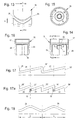
- a paste dispenser is shown, which is provided with a dosing pump 1 forming the head part and has a cylindrical container 2. Both the metering pump 1 and the container are each made of plastic.
- a follower piston 3 In the cylindrical container 2 is a follower piston 3.
- a bearing cage 5 for a valve plug 6 In the center of an upper end wall 4 of the container 2 is a bearing cage 5 for a valve plug 6, the annular disc circumference 7 in cooperation with a conical annular surface 8 of the bearing cage 5, a suction valve 5 ( Fig. 8 ).
- An upwardly projecting annular wall 9 is used for sealing receiving a ring collar 10 at the lower end of a resilient bellows 11 made of plastic, the upper annular end wall 12 by means of a ring neck 13 a cylindrical guide sleeve 14 sealingly surrounds.
- This guide sleeve 14 is an integral part of a cylindrical, upper housing part 15, which has an end wall 16, on which the guide sleeve 14 is integrally formed.
- a cylindrical end cap 18 which has a dispensing opening 21 in a concavely recessed area 19 of an end wall 20, is fastened in an annular wall section 17 projecting upwards beyond the end wall 16.
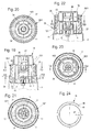
- FIG. 13 to 16 As an item without end cap 18 shown upper housing part 15 is provided in the lower region of its cylindrical circumference with two diametrically opposed, thread-like extending guide grooves 26 whose axial length s corresponds to the pumping stroke of the housing part 15 and in which each one on the cylindrical inner surface 31 of a cylindrical Rotary sleeve 30 arranged nut 32 engages.
- This rotary sleeve 30 is in the Fig. 10 to 12a shown as a single part.
- this rotary sleeve 30 is rotatably and axially immovably mounted in an annular wall 27 of the integrally connected to the container 2 lower housing part 28, so that by their rotation relative to the upper housing part 15 due to the engagement of the sliding blocks 32 with the guide grooves 26 an axial movement of the Upper housing part 15 relative to the lower housing part 28 comes about.
- the upper housing part 15 As best of the 6 and 7 can be seen, provided with two diametrically opposed, inwardly projecting axially parallel ribs 33 which engage in axially parallel guide slots 29 of an inner, upwardly projecting annular wall 34 of the lower housing part 28.
- annular wall 34 is arranged concentrically to the outer annular wall 27 and to the annular wall 9.
- the guide grooves 26 can according to Fig. 18 sinusoidally running without any interchange. But there is also the more advantageous possibility, 26 'to connect the ends of the two guide grooves each by axially parallel connecting grooves, so that in each case the beginning of a guide groove 26 is connected to the end of the other guide groove by such an axially extending connecting groove 26' , In this case, it is more advantageous cylindrical sliding blocks 32 according to Fig. 12a while diamond-shaped sliding blocks 32 can be used with sinusoidal guide grooves 26 that merge into one another without offset.
- FIGS. 17 and 18 While in the embodiments of the FIGS. 17 and 18 The guide grooves 26 each extend over half the circumference of the axially movable housing part 15 and thus the rotary sleeve 30 must be rotated to perform a full pumping stroke in each case by 180 °, there is according to Fig. 17a also the possibility the circumferential length of the guide grooves 26 to limit to a quarter of the circumference or at an angle of 90 °, so that in each case only rotational movements of the rotary sleeve 30 of 90 ° are required for the execution of a full pumping stroke.
- the sliding blocks 32 should each have a matched to the pitch and width of both the guide grooves 26 and the connecting grooves 26' cross-sectional shape of a rate or a rhombus, as in Fig. 17a hatched shown.
- the upper, protruding from the annular wall 27 part of the rotary sleeve 30 is provided with a handle knurl 35.
- the guide grooves 26 are symmetrical with respect to a radial plane 36 extending in the axial direction and that with them two axially at the same height h (FIG. Figure 11 ) diametrically opposite to the inside 31 of the rotary sleeve 30 arranged sliding blocks 32 are engaged.
- h FIG. Figure 11
- the rotatable, but axially immovable mounted in the annular wall 27 of the lower housing part 28 rotary sleeve 30 has a lower portion 30 'with a smooth outer surface 31' on. Between the handle portion portion 35 and the smooth peripheral portion 31 'there is a radial annular shoulder 37 against which an inwardly projecting annular collar 38 of the annular wall 27 of the lower housing part 28 bears in a fixed manner. Characterized in that at the same time the lower end edge 39 of the rotary sleeve 30 is seated on the end wall 4, the rotary sleeve 30 is axially fixed within the region of the annular wall 27. Due to the material elasticity of the housing body made of plastic, the lower portion 30 'of the rotary sleeve 30 can relatively easily from the top into the annular wall 27 to use in the finished state in Fig. 8 take position shown.
- FIGS. 19 to 33 an embodiment of the metering pump 1 according to the invention is shown, in which the thread-like engagement elements consist of one or more threads 41 and 43 of the axially movable housing part 15/1 on the one hand and the rotary sleeve 30/1 on the other.
- FIGS Fig.1 to 18 The other structure is the same as in the embodiment shown in FIGS Fig.1 to 18 is shown.
- the movable housing part 15/1 is as an item in the FIGS. 28 and 29 and together with the end cap 18 in the FIGS. 26 and 27 shown.
- the housing part 15/1 has an annular wall 17 into which the end cap 18 in the in Fig. 3 and 8th illustrated manner is used.
- a lower portion of the circumference of the housing part 15/1 is provided with a multi-thread external thread 41 whose individual threads have the cross-sectional profile of a saw thread (such as. From DIN 513 and 514 known). From the FIGS. 26 and 28 It can be seen that the outer diameter d of the external thread 41 is larger than the diameter of the Ring wall 17, so that between these two an outwardly projecting flat annular shoulder 42 is formed at which the individual threads end.
- the pitch of the threads or a height difference of a thread should be at least twice as large as the maximum pumping stroke of the movable housing part 15/1, so that a rotational movement of the rotary sleeve 30/1 180 ° is sufficient to perform a full pump stroke.
- rotary sleeve 30/1 is provided at its upper end with a closed annular flange 44, which serves for the threads of the external thread 41 as an axial stroke stop on which the annular shoulder 42nd in the initial position or rest position of the movable housing part 15/1 abuts axially.
- the internal thread 43 is open, so that the rotary sleeve can be screwed onto the external thread 41 from above.
- a helical return spring 46 is arranged in a recess 50 the lower end face 51 of the rotary sleeve 30/1 is housed.
- This in Fig. 24 shown as an item return spring 46 has at its inner end a locking plate 47 which engages lockingly in one of the recesses 29 of the annular wall 34 of the lower housing part 28.
- the outer end 48 of the return spring 46 is provided with an upwardly bent engagement pin 49 which engages positively in a slot-like recess 52 of the rotary sleeve 30/1.
- the return spring 46 is on the one hand positively connected to the lower housing part 28 and on the other hand positively connected to the rotary sleeve 30/1, and they can perform with appropriate bias the reverse rotation of the rotary sleeve 30/1 after each pump stroke. If the thread pitch is chosen so that there is no self-locking, the restoring force of the bellows for turning back may be sufficient.
- the axially movable housing part 15/1 is provided with inwardly projecting ribs 33, the form-fitting, but axially movable, engage in the guide slots 29 of the annular wall 34 of the lower housing part 28 and thereby rotational movements of the movable housing part 15/1 relative to prevent lower housing part 28.
- the rotary sleeve 30/1 is mounted in the same manner in the annular wall 27 of the lower housing part 28 as the rotary sleeve 30 in the previously described embodiment and therefore also provided with an annular shoulder 37. Also, the handle knurl 35 is present in the same manner as in the rotary sleeve 30th
- a handle knurl and grip grooves could be provided, as in Fig.1 is shown.
- a pumping stroke is also carried out here by a corresponding rotational movement of the rotary sleeve 30/1 while the container 2 or the housing base 28 is retained.
- the return spring 46 After releasing the rotary sleeve 30/1 it is rotated back by the return spring 46 back to its original position and thereby the bellows 11 is relaxed again, wherein at the same time takes place during the relaxation process, a new suction for the issue with the next pump stroke medium.
- the guide grooves have, as well as from the FIGS. 14 and 16 can be seen, in the lower part of an insertion bevel, so as to allow during assembly overflow of the sliding block.
- the sleeve at least in the region of the sliding block, be formed double-walled. This also increases the flexibility of the sliding block when overflowing the insertion and snapping into the guide grooves.
- the sleeve is also preferably provided such that, in the case of the double wall with its outer wall, the annular wall 27 engages over the outside.
- the annular wall 27 engages over the outside.
- two (respectively) two correspondingly spaced-apart ribs can also be formed.
Description
- Die Erfindung betrifft eine Dosierpumpe nach den Merkmalen des Oberbegriffes des Anspruches 1. Es handelt sich insgesamt um einen Spender, der durch Pumpbewegung Medium ausgibt.
- Im Einzelnen kann die Dosierpumpe aus Kunststoff bestehen und der Spender ein Pastenspender sein. Grundsätzlich ist aber auch die Ausgabe von flüssigem Medium möglich. Das Medium, also bevorzugt das pastenartige Medium, wird aus einem flaschen-, dosen- oder tubenartigen Behälter mit Nachlaufkolben ausgegeben, wobei ein das Medium förderndes Pumporgan aus einem mit einem selbsttätigen Ansaugventil und einem selbsttätigen Auslassventil versehenen, federelastischen, und selbstansaugenden Faltenbalg besteht. Der Faltenbalg ist bevorzugt zwischen einem zylindrischen, formstabilen, mit dem Behälter unbeweglich verbundenen, unteren Gehäuseteil und einem axial dazu beweglichen, ebenfalls zylindrischen und formstabilem oberen Gehäuseteil angeordnet ist, der durch die axiale Bewegung des oberen Gehäuseteils zur Mediumabgabe komprimierbar ist.
- Dosierpumpen der gattungsgemäßen Art sind in vielen Variationen bekannt, z. B. aus
DE 35 09178 A1 ,DE 8713 891.3 U1 ,DE 38 28 811 A1 ,DE 38 34 091 A1 ,DE 42 12 413C2 ,DE 38 44 854 C2 ,DE 40 41136 C2 ,EP 0 304 567 B1 ,EP 312 722 B1 EP 1 170 062 A2 . - Diese bekannten Dosier- oder Spraypumpen haben das Merkmal gemeinsam, dass der sich im beweglichen Gehäuseteil befindende Auslass für das auszugebende Medium radial nach außen gerichtet ist und durch einen im Wesentlichen radial verlaufenden Kanal über ein selbsttätig schließendes Auslassventil mit dem Innenraum des Faltenbalgs in Verbindung steht. Dabei kann das Auslassventil unterschiedlich ausgebildet sein, z. B. in Form einer elastischen Ringmanschette, die eine Ringwand des beweglichen Gehäuseteils umschließt, oder als axial beweglicher Stöpsel, der unter leichtem Federdruck auf einer ringförmigen Ventilfläche aufsitzt und von dieser abgehoben werden kann, wenn ein Pumphub erfolgt.
- Auch die Ansaugventile, welche den Innenraum des Faltenbalgs mit dem Hohlraum des Mediumbehälters verbinden, können unterschiedlich ausgeführt sein.
- Bei diesen bekannten Dosierpumpen erfolgt die Betätigung des axial beweglichen Gehäuseteils in der Weise, dass ein Finger, vorzugsweise der Daumen einer menschlichen Hand, welche das Pumpengehäuse bzw. den Behälter umfasst, stirnseitig auf das bewegliche Gehäuseteil drückt, um einen Pumphub auszuführen. Beim Loslassen bzw. Freigeben wird das bewegliche Gehäuseteil durch die dem Faltenbalg innewohnende Federkraft wieder in die Ausgangslage zurückgestellt.
- Wegen dieser Art der Betätigung durch einen stirnseitig aufgelegten Finger, ist es erforderlich, die Ausgabeöffnung seitlich am beweglichen Gehäuseteil anzuordnen, damit der dieses Gehäuseteil betätigende Finger mit dem auszugebenden Medium während des Pumphubs nicht in Berührung kommt bzw. die Ausgabeöffnung nicht verschließt.
- Es ist aber auch bereits ein sog. Flüssigkeits-Applikator bekannt, der eine ballige Applikationsfläche aufweist, in deren Scheitelbereich eine Mündungsöffnung für die Ausgabe des Mediums angeordnet ist. Diese Applikationsfläche stellt zugleich die Betätigungsfläche dar. Bei diesem Applikator wird die Betätigung aber nicht durch einen Finger bewerkstelligt sondern dadurch, dass die ballige Applikationsfläche direkt auf die Haut eines mit der Flüssigkeit zu behandelnden menschlichen Körpers gedrückt wird. Dabei ist es wohl erforderlich, die ballige Fläche schräg aufzusetzen, damit der den Abschluss der Ausgabeöffnung bildende Ventilstöpsel von seiner Ventilsitzfläche in axialer Richtung abheben und eine Flüssigkeitsabgabe ermöglichen kann. Für die dosierte Abgabe pastöser Medien ist dieser Flüssigkeits-Applikator nicht geeignet.
- Außerdem ist der Behälter dieses Flüssigkeitsapplikators nicht mit einem Nachlaufkolben versehen.
- Aus der
DE-OS 28 42 073 ist auch ein handbetätigter Pumpdispensor bekannt, der auf einen Fluidbehälter aufsetzbar ist und mittels einer sog. Überwurfmutter auf den Gewindehals eines Flüssigkeitsbehälters aufgeschraubt werden kann. Als Pumporgan besitzt dieser Pumpdispensor einen axial elastischen Faltenbalg. Dieser Faltenbalg wird jedoch nicht zur Ausführung von Pumphüben direkt manuell über ein axial bewegliches Gehäuseteil betätigt. Es sind vielmehr zwei durch Gewindeeingriff miteinander verbundene Gewindehülsen vorgesehen, von denen eine ortsfest, aber drehbar im Pumpengehäuse angeordnet und die andere axial beweglich, aber undrehbar darin geführt ist. Dabei steht die axial bewegliche Hülse unter dem Einfluss einer axialen Druckfeder, welche den Ausgabedruck für das auszugebende Fluid aufzubringen hat. Die ortsfest, jedoch drehbar gelagerte Hülse wird zum Spannen der Druckfeder gedreht, so dass sich unter gleichzeitiger Verlängerung des Faltenbalgs die bewegliche Hülse von der ortsfesten Hülse wegbewegt. - Das obere Ende des Faltenbalgs ist dabei mit einem Gehäuseteil verbunden, in dem ein manuell zu betätigendes Auslassventil angeordnet ist. Dieses Auslassventil ist mit einem Dispenser-Sprühkopf verbunden, der gedrückt werden kann, um das Auslassventil zu öffnen. Wenn und solange das Auslassventil geöffnet ist, wird durch den von der Druckfeder auf den Faltenbalg ausgeübten Pressdruck Flüssigkeit aus dem Innern des Faltenbalgs durch den Sprühkopf nach außen gepresst und versprüht.
- Es handelt sich also um einen Permanentsprüher, wobei die Drehbewegungen einen danach zum Versprühen nutzbaren Federspeicher aufladen. Solches ist insbesondere vorgeschlagen worden, um Treibgas zu ersetzen.
- Der Erfindung liegt die Aufgabe zugrunde, eine Dosierpumpe der eingangs genannten Art zu schaffen, bei welcher der Pumpvorgang vorteilhaft bewirkt werden kann. Diese Aufgabe ist beim Gegenstand des Anspruches 1 gelöst.
- Die weiteren Ansprüche betreffen einerseits vorteilhafte weitere Merkmale. Andererseits können die Merkmale eines weiteren Anspruches aber auch je für sich, unabhängig von den Merkmalen vor- oder nachstehender Ansprüche, von Bedeutung sein.
- Zwischen dem unteren Gehäuseteil und dem axial beweglichen oberen Gehäuseteil ist bevorzugt eine im unteren Gehäuseteil drehbar gelagerte Drehhülse angeordnet, welche mit dem axial beweglichen Gehäuseteil über gewindeartige Eingriffselemente in Eingriff steht, die Drehbewegungen der Drehhülse in axiale Hubbewegungen des oberen Gehäuseteils umwandeln. Andererseits ist es auch möglich, dass das axial bewegliche Gehäuseteil zugleich auch drehbeweglich ist, etwa in Zusammenwirkung mit einem feststehenden äußeren oder inneren, der drehbeweglichen Hülse entsprechenden Teil.
- Die so ausgebildete Dosierpumpe hat vor allem den Vorteil, dass unmittelbar einhergehend mit einer (Ausgabe-) Drehbewegung Medium ausgegeben wird. Das Auslassventil wird durch den vermittelst der Drehbewegung erzeugten (Über-) Druck zwangsgeöffnet. Danach, nach Abbau des (Über-) Druckes schließt es genauso selbsttätig wie es selbsttätig geöffnet hat. Gleiches gilt - umgekehrt - für das Einlassventil. Es ist eine vorteilhafte Drehbetätigung möglich und zugleich eine gute Dosierung des ausgegebenen Mediums. Bei der Rückdrehbewegung (die nicht notwendig eine Drehbewegung sein muss, sondern grundsätzlich auch alleine eine Vertikalbewegung sein kann) der Hülse wird natürlich kein Medium ausgegeben. Die einzelnen Pumphübe werden durch das Drehen eines Betätigungsorgans, nämlich der Drehhülse, ausgeführt, so dass kein Finger der den Behälter der Dosierpumpe haltemden Hand auf der Stirnseite der Dosierpumpe aufliegen muss. Es besteht die Möglichkeit, die Ausgabeöffnung auf der Stirnseite, vorzugsweise in deren Zentrum, anzubringen. Mit der Ausgestaltung, dass der zylindrische Umfang des axial beweglichen Gehäuseteils mit Führungsnuten, gewindeartig, versehen ist, deren axiale Länge dem Pumphub entspricht und in welche jeweils ein an der Innenseite der Drehhülse angeordneter Nutenstein eingreift, ergibt sich nicht nur ein einfacher Aufbau, sondern auch eine leichte und einfache Handhabung bzw. Bedienungsweise der Dosierpumpe, wobei die vorteilhafte Möglichkeit besteht, alle Teile aus Kunststoff im Spritzgussverfahren herzustellen und maschinell bzw. automatisch zu montieren.
- Mit der Maßnahme, dass sich die Führungsnuten jeweils maximal über den halben Umfang des beweglichen Gehäuseteils erstrecken und/oder die Enden der Führungsnuten durch axial verlaufende Verbindungsnuten mit dem Anfang der jeweils anderen Führungsnut verbunden sind, kann die für die Ausführung eines kompletten Pumphubs erforderliche Drehbewegung auf 180° bzw. 90° beschränkt werden, was ebenfalls zur Erleichterung der Handhabung beiträgt. Durch diese Ausgestaltung wird zugleich eine einem vollen Pumphub entsprechende Drehbewegung des Betätigungsorgans, d.h. der Drehhülse festgelegt, wobei jeweils am Ende der Drehbewegung das mit dem oberen Ende des Faltenbalgs verbundene, axial bewegliche Gehäuseteil, durch die rückstellende Federkraft des Faltenbalgs selbsttätig in seine Ausgangslage zurückkehren kann, in dem der oder die Nutensteine durch die axial verlaufenden Verbindungsnuten gleiten können.
- Eine in sich geschlossene, im Wesentlichen sinusförmig verlaufende Führungsnut, in welche wenigstens ein an der Innenseite der Drehhülse angeordneter Nutenstein eingreift, und/oder die Maßnahme, dass die Führungsnut in Umfangsrichtung über zwei Wellenlängen einer Sinuskurve sich erstreckt, stellen dazu vorteilhafte Lösungen dar.
- Ein symmetrischer Verlauf - bezogen auf eine Radialebene - der Führungsnut und zwei diametral gegenüberliegend eingreifende Nutensteine sind insbesondere für eine leichtgängige Funktionsweise vorteilhaft.
- Es ist möglich, dass die gewindeartigen Eingriffselemente aus einem oder mehreren Gewindegängen bestehen. Und zwar weiter bevorzugt an beiden zusammenwirkenden Teilen, dem beweglichen Gehäuseteil und der Drehhülse. Hierbei kann die Form eines Sägengewindes realisiert sein. Die Steigung der Gewindegänge ist bevorzugt wenigstens doppelt so groß wie der maximale Pumphub des beweglichen Gehäuseteils. Hierbei ist mit Steigung auch die absolute Höhe des Gewindegangs angesprochen. Der maximale Pumphub kann entweder durch eine halbe Umdrehung oder eine viertel Umdrehung des Betätigungsorgans, d. h. der Drehhülse, erreicht werden. Dies insbesondere dann, wenn die genannte Steigung der Gewindegänge dem vierfachen Pumpenhub entspricht.
- Es sind Vorkehrungen getroffen, dass die gewindeartigen Eingriffselemente nicht ungewollt außer Eingriff voneinander gebracht werden können und die Funktionstüchtigkeit der Dosierpumpe nicht durch unsachgemäße Behandlung in Frage gestellt werden kann.
- Es ist auch vorteilhaft, wenn, ggf. zusätzlich zu dem insoweit auch als Rückstellfeder wirkenden Pumpenbalg, eine gesonderte Rückstellfeder vorgesehen ist, so dass die Drehhülse und der Faltenbalg nach jedem Pumphub wieder selbsttätig in ihre Ausgangslage zurückkehren können.
- Es können auch Sicherungselemente vorgesehen sein, die in Umfangsrichtung formschlüssig ineinander greifen und so gegen relatives Verdrehen sichern. Hierdurch ist erreicht, dass durch die Drehbewegung der Drehhülse kein Drehmoment auf den Faltenbalg ausgeübt wird und sich das axial bewegliche Gehäuseteil bei der Drehung der Drehhülse selbst nicht mitdrehen kann.
- Bevorzugt ist auch, dass das auszugebende Medium nach einem Pumphub in einer stirnseitigen Vertiefung der Abschlusskappe liegen bleibt und von dort mit einem Finger leicht entnommen werden kann.
- Die Griffigkeit der Drehhülse kann durch einen Griffrändel erhöht sein, und somit deren Betätigung durch Drehen erleichtert sein.
- Die Erfindung wird im Folgenden anhand der beiliegenden Zeichnungen näher erläutert. Es zeigt:
- Fig.1
- in isometrischer Seitenansicht eine auf einem zylindrischen Behälter aufgesetzte Dosierpumpe;
- Fig. 2
- den unteren Gehäuseteil der Dosierpumpe mit dem angeformten Behälter in verkürzter Schnittdarstellung;
- Fig. 3
- im Schnitt die wesentlichen Teile der Dosierpumpe;
- Fig. 4
- eine Ansicht F4 aus
Fig. 2 ; - Fig. 5
- eine Ansicht F5-F5 aus
Fig. 4 ; - Fig. 6
- eine Schnittansicht F6-F6 aus
Fig. 3 ; - Fig. 7
- eine Schnittansicht F7-F7 aus
Fig. 3 ; - Fig. 8
- im Schnitt die komplette Dosierpumpe bei ausgeführtem Pumphub;
- Fig. 9
- eine Schnittansicht F9-F9 aus
Fig. 8 , wobei die Drehhülse gegenüber denFig. 3 ,6 und 9 um 90° gedreht ist; - Fig. 10
- die Drehhülse in Draufsicht F10 aus
Fig.11 ; - Fig.11
- eine Schnittansicht F11-F11 aus
Fig. 10 ; - Fig. 12
- eine Schnittansicht F12-F12 aus
Fig. 10 ; - Fig. 12a
- die gleiche Schnittdarstellung wie
Fig. 12 , jedoch mit einer anderen Querschnittsform des Nutensteins; - Fig. 13
- das bewegliche Gehäuseteil in Seitenansicht;
- Fig. 14
- eine Schnittansicht F14-F14 aus
Fig. 13 ; - Fig. 15
- eine Ansicht F15 aus
Fig. 14 ; - Fig. 16
- eine Schnittansicht F16-F16 aus
Fig. 14 ; - Fig. 17
- eine Ausführungsform der Führungsnut des beweglichen Gehäuseteils in der Abwicklung;
- Fig. 17a
- die Abwicklung einer vierteiligen Führungsnut;
- Fig. 18
- eine andere Ausführungsform der Führungsnuten des beweglichen Gehäuseteils in der Abwicklung;
- Fig. 19
- im Schnitt eine andere Ausführungsform der Dosierpumpe;
- Fig. 20
- eine Schnittansicht F20-F20 aus
Fig. 19 ; - Fig. 21
- eine Schnittansicht F21-F21 aus
Fig. 19 ; - Fig. 22
- die Dosierpumpe der
Fig. 19 bei ausgeführtem Pumphub; - Fig. 23
- eine Schnittansicht F23-F23 aus
Fig. 22 ; - Fig. 24
- eine spiralförmige Rückstellfeder in Draufsicht;
- Fig. 25
- in stark vergrößerter Schnittdarstellung die Anordnung der Rückstellfeder im eingebauten Zustand;
- Fig. 26
- das komplette bewegliche Gehäuseteil mit dem Gewindeabschnitt und der aufgesetzten Abschlusskappe in Seitenansicht;
- Fig. 26a
- eine andere Ausführungsform des beweglichen Gehäuseteils in Seitenansicht;
- Fig. 27
- eine Ansicht F27 aus
Fig. 26; Fig. 27a eine Ansicht F27a ausFig. 26a ; - Fig. 28
- das bewegliche Gehäuseteil ohne Abschlusskappe im Schnitt;
- Fig. 29
- eine Schnittansicht F29-F29 aus
Fig. 28 ; - Fig. 30
- die Abdeckkappe als Einzelteil im Schnitt;
- Fig. 31
- die mit einem Innengewinde versehene Drehhülse in Stirnansicht;
- Fig. 32
- eine Schnittansicht F32-F32 aus
Fig. 31 ; - Fig. 33
- eine Ansicht F33 aus
Fig. 32 . - In
Fig.1 ist ein Pastenspender dargestellt, der mit einer den Kopfteil bildenden Dosierpumpe 1 versehen ist und einen zylindrischen Behälter 2 aufweist. Sowohl die Dosierpumpe 1 als auch der Behälter bestehen jeweils aus Kunststoff. Im zylindrischen Behälter 2 befindet sich ein Nachlaufkolben 3. Im Zentrum einer oberen Stirnwand 4 des Behälters 2 befindet sich ein Lagerkäfig 5 für einen Ventilstöpsel 6, dessen Ringscheibenumfang 7 im Zusammenwirken mit einer konischen Ringfläche 8 des Lagerkäfigs 5 ein Ansaugventil 5' (Fig. 8 ) bildet. - Eine nach oben vorspringende Ringwand 9 dient der dichtenden Aufnahme einer Ringmanschette 10 am unteren Ende eines federelastischen Faltenbalgs 11 aus Kunststoff, dessen obere ringförmige Stirnwand 12 mittels eines Ringansatzes 13 einen zylindrischen Führungsstutzen 14 dichtend umschließt. Dieser Führungsstutzen 14 ist einstückiger Bestandteil eines zylindrischen, oberen Gehäuseteils 15, das eine Stirnwand 16 aufweist, an welcher der Führungsstutzen 14 einstückig angeformt ist.
- In einem die Stirnwand 16 nach oben überragenden Ringwandabschnitt 17 ist eine zylindrische Abschlusskappe 18 befestigt, die in einem konkav vertieften Bereich 19 einer Stirnwand 20 eine Ausgabeöffnung 21 aufweist. Eine innere Ringwand 22, die dichtend auf der Stirnwand 16 des Gehäuseteils 15 aufsitzt, bildet eine Ventilkammer 23 und umschließt einen Ventilstöpsel 24, der im Zusammenwirken mit einer konischen Ringfläche 25 des Führungsstutzens 14 ein selbsttätig öffnendes und schließendes Auslassventil 26 bildet.
- Das in
Fig. 13 bis 16 als Einzelteil ohne Abschlusskappe 18 dargestellte obere Gehäuseteil 15 ist im unteren Bereich seines zylindrischen Umfangs mit zwei sich diametral gegenüberliegenden, gewindeartig verlaufenden Führungsnuten 26 versehen, deren axiale Länge s dem Pumphub des Gehäuseteils 15 entspricht und in welche jeweils ein an der zylindrischen Innenfläche 31 einer zylindrischen Drehhülse 30 angeordneter Nutenstein 32 eingreift. Diese Drehhülse 30 ist in denFig. 10 bis 12a als Einzelteil dargestellt. - Wie aus
Fig. 8 ersichtlich ist, ist diese Drehhülse 30 in einer Ringwand 27 des einstückig mit dem Behälter 2 verbundenen unteren Gehäuseteils 28 drehbar und axial unbeweglich gelagert, so dass durch ihre Drehung relativ zum oberen Gehäuseteil 15 infolge des Eingriffs der Nutensteine 32 mit den Führungsnuten 26 eine Axialbewegung des oberen Gehäuseteils 15 relativ zum unteren Gehäuseteil 28 zustande kommt. - Um dabei ein Mitdrehen des oberen Gehäuseteils 15 zu verhindern, ist das obere Gehäuseteil 15, wie am besten aus den
Fig. 6 und 7 ersichtlich ist, mit zwei sich diametral gegenüberliegenden, nach innen vorspringenden achsparallel verlaufenden Rippen 33 versehen, die in achsparallele Führungsschlitze 29 einer inneren, nach oben ragenden Ringwand 34 des unteren Gehäuseteils 28 eingreifen. - Wie am besten aus
Fig. 4 ersichtlich ist, ist die Ringwand 34 konzentrisch zur äußeren Ringwand 27 bzw. zur Ringwand 9 angeordnet. - Die Führungsnuten 26 können gemäß
Fig. 18 sinusförmig verlaufend absatzlos ineinander übergehen. Es besteht aber auch die vorteilhaftere Möglichkeit, die Enden der beiden Führungsnuten 26 jeweils durch achsparallel verlaufende Verbindungsnuten 26' miteinander zu verbinden, so dass jeweils der Anfang der einen Führungsnut 26 mit dem Ende der anderen Führungsnut durch eine solche axial verlaufende Verbindungsnut 26' verbunden ist. In diesem Falle ist es vorteilhafter, zylindrische Nutensteine 32 gemäßFig. 12a zu verwenden, während bei sinusförmigen Führungsnuten 26, die absatzlos ineinander übergehen, rautenförmige Nutensteine 32 verwendet werden können. - Bei der Verwendung von Führungsnuten 26, die gemäß
Fig. 17 durch axiale Verbindungsnuten 26' miteinander verbunden sind, dienen die axial verlaufenden Verbindungsnuten 26' für die Nutensteine 32 zugleich als hubbegrenzende Anschläge. Sobald ein Nutenstein 32 am unteren Ende einer Verbindungsnut 26' angekommen ist und er gegen die achsparallele Seitenwand dieser Verbindungsnut 26' anschlägt, wird die Drehbewegung der Drehhülse 30 gestoppt. In dieser Lage der Nutensteine 32 kann, sich der Faltenbalg 11 wieder entspannen und das Gehäuseteil 15 wieder in seine obere Lage zurückschieben. Die Dosierpumpe ist dann sofort wieder bereit für einen neuen Pumphub, der durch eine Drehung der Drehhülse 30 in Pfeilrichtung 40 (Fig. 17 ) um 180° bewirkt werden kann. - Während sich bei den Ausführungsformen der
Fig. 17 und 18 die Führungsnuten 26 jeweils über den halben Umfang des axial beweglichen Gehäuseteils 15 erstrecken und somit die Drehhülse 30 zur Ausführung eines vollen Pumphubes jeweils um 180° gedreht werden muss, besteht gemäßFig. 17a auch die Möglichkeit, die Umfangslänge der Führungsnuten 26 auf ein Viertel des Umfangs bzw. auf einen Winkel von 90° zu begrenzen, so dass für die Ausführung eines vollen Pumphubes jeweils nur Drehbewegungen der Drehhülse 30 von 90° erforderlich sind. - Bei dieser Ausführungsform der Führungsnuten 26, deren Enden wie bei der Ausführungsform der
Fig.17 jeweils durch axiale Verbindungsnuten 26' miteinander verbunden sind, sollten die Nutensteine 32 jeweils eine auf die Steigung und Breite sowohl der Führungsnuten 26 als auch der Verbindungsnuten 26' abgestimmte Querschnittsform einer Rate bzw. eines Rhombus haben, wie inFig. 17a schraffiert dargestellt. - Zweckmäßiger Weise ist der obere, aus der Ringwand 27 herausragende Teil der Drehhülse 30 mit einem Griffrändel 35 versehen.
- Bei der sinusförmig ausgebildeten Führungsnut 26, die sich über zwei Wellenlängen (2xλ) erstreckt, weist diese somit zwei sich jeweils paarweise diametral gegenüberliegende Wellenberge und Wellentäler auf, was aus
Fig. 18 zu erkennen ist. - Wichtig dabei ist auch, dass die Führungsnuten 26 im Bezug auf eine in Achsrichtung verlaufende Radialebene 36 symmetrisch verlaufen und dass mit ihnen zwei sich in axial gleicher Höhe h (
Fig.11 ) diametral gegenüberliegend an der Innenseite 31 der Drehhülse 30 angeordnete Nutensteine 32 in Eingriff stehen. Durch diese Ausgestaltung wird auch bei relativ großer Steigung der Führungsnut bzw. Führungsnuten 26 eine leicht gängige Betätigung des axial beweglichen Gehäuseteils 15 durch Drehung der Drehhülse 30 gewährleistet. - Die drehbar, jedoch axial unbeweglich in der Ringwand 27 des unteren Gehäuseteils 28 gelagerte Drehhülse 30, weist einen unteren Abschnitt 30' mit einer glatten Außenfläche 31' auf. Zwischen dem Griffteilabschnitt 35 und dem glatten Umfangsabschnitt 31' besteht eine radiale Ringschulter 37, an welcher ein nach innen vorspringender Ringbund 38 der Ringwand 27 des unteren Gehäuseteils 28 fixierend anliegt. Dadurch, dass zugleich die untere Stirnkante 39 der Drehhülse 30 auf der Stirnwand 4 aufsitzt, ist die Drehhülse 30 innerhalb des Bereichs der Ringwand 27 axial fixiert. Aufgrund der Materialelastizität des aus Kunststoff bestehenden Gehäusekörpers lässt sich der untere Abschnitt 30' der Drehhülse 30 relativ leicht von oben in die Ringwand 27 einsetzen, um im fertigen Zustand die in
Fig. 8 dargestellte Position einzunehmen. - In den
Fig. 19 bis 33 ist eine Ausführungsform der erfindungsgemäßen Dosierpumpe 1 dargestellt, bei der die gewindeartigen Eingriffselemente aus einem oder mehreren Gewindegängen 41 bzw. 43 des axial beweglichen Gehäuseteils 15/1 einerseits und der Drehhülse 30/1 andererseits bestehen. - Der übrige Aufbau ist der Gleiche wie bei der Ausführungsform, die in den
Fig.1 bis 18 dargestellt ist. - Das bewegliche Gehäuseteil 15/1 ist als Einzelteil in den
Fig. 28 und 29 und gemeinsam mit der Abschlusskappe 18 in denFig. 26 und 27 dargestellt. Wie das Gehäuseteil 15 weist auch das Gehäuseteil 15/1 eine Ringwand 17 auf, in welche die Abschlusskappe 18 in der inFig. 3 und8 dargestellten Weise eingesetzt ist. Statt der Führungsnuten ist ein unterer Abschnitt des Umfangs des Gehäuseteils 15/1 mit einem mehrgängigen Außengewinde 41 versehen, dessen einzelne Gewindegänge das Querschnittsprofil eines Sägengewindes (wie bspw. aus DIN 513 und 514 bekannt) aufweisen. Aus denFig. 26 und 28 ist erkennbar, dass der Außendurchmesser d des Außengewindes 41 größer ist als der Durchmesser der Ringwand 17, so dass zwischen diesen beiden eine nach außen vorspringende planebene Ringschulter 42 gebildet ist, an der die einzelnen Gewindegänge enden. - Die übrigen Bestandteile des beweglichen Gehäuseteils 15/1 entsprechen denjenigen des Gehäuseteils 15. Die Steigung der Gewindegänge bzw. eine Höhendifferenz eines Gewindeganges sollte wenigstens doppelt so groß sein wie der maximale Pumphub des beweglichen Gehäuseteils 15/1, damit eine Drehbewegung der Drehhülse 30/1 um 180° ausreicht, um einen vollen Pumphub auszuführen.
- Vorteilhafter ist es jedoch, die Steigung der Gewindegänge so auszulegen, dass sie dem vierfachen Pumphub entsprechen, so dass eine Drehung der Drehhülse 30/1 um 90° ausreicht, um einen vollen Pumphub auszuführen.
- Die mit einem auf das Außengewinde 41 des beweglichen Gehäuseteils 15/1 abgestimmten Innengewinde 43 versehene Drehhülse 30/1 ist an ihrem oberen Ende mit einem geschlossenen Ringflansch 44 versehen, der für die Gewindegänge des Außengewindes 41 als axialer Hubanschlag dient, an dem die Ringschulter 42 in der Ausgangslage bzw. Ruhelage des beweglichen Gehäuseteils 15/1 axial anliegt. An der Unterseite der Drehhülse 30/1 ist das Innengewinde 43 offen, so dass die Drehhülse von oben auf das Außengewinde 41 aufgeschraubt werden kann.
- Es zu erwähnen, dass es ausreichen würde, das Außengewinde 41 auf drei oder vier auf dem Umfang verteilte Gewindegänge zu beschränken, die mit den vollständig vorhandenen Gewindegängen des Innengewindes 43 der Drehhülse 30/1 in Eingriff stehen, wie in den
Fig. 26a und 27a dargestellt. Die zwischen den Gewindegängen des Außengewindes 41 und des Innengewindes 43 bestehenden Reibungsflächen der Gewindeflanken könnten dadurch erheblich reduziert und somit die Betätigung erleichtert werden. - Um nach jeder einen Pumphub erzeugenden Drehbewegung der Drehhülse 30/1, wieder eine automatische Rückwärts-Drehbewegung dieser Drehhülse 30/1 zu erreichen, ist zwischen dem unteren Gehäuseteil 28 und der Drehhülse 30/1 eine spiralförmige Rückstellfeder 46 angeordnet, die in einer Ausnehmung 50 der unteren Stirnseite 51 der Drehhülse 30/1 untergebracht ist. Diese in
Fig. 24 als Einzelteil dargestellte Rückstellfeder 46 weist an ihrem inneren Ende eine Arretierplatte 47 auf, welche in eine der Ausnehmungen 29 der Ringwand 34 des unteren Gehäuseteils 28 arretierend eingreift. Das äußere Ende 48 der Rückstellfeder 46 ist mit einem nach oben abgebogenen Eingriffszapfen 49 versehen, der in eine schlitzartige Ausnehmung 52 der Drehhülse 30/1 formschlüssig eingreift. Auf diese Weise ist die Rückstellfeder 46 einerseits formschlüssig mit dem unteren Gehäuseteil 28 und andererseits formschlüssig mit der Drehhülse 30/1 verbunden, und sie kann mit entsprechender Vorspannung die Rückdrehbewegung der Drehhülse 30/1 nach jedem ausgeführten Pumphub durchführen. Wenn die Gewindesteigung so gewählt ist, dass keine Selbsthemmung vorliegt, kann auch die Rückstellkraft des Faltenbalges zum Zurückdrehen ausreichend sein. - Auch bei dieser Ausführungsform ist das axial bewegliche Gehäuseteil 15/1 mit nach innen vorspringenden Rippen 33 versehen, die formschlüssig, jedoch axial beweglich, in die Führungsschlitze 29 der Ringwand 34 des unteren Gehäuseteils 28 eingreifen und dadurch Drehbewegungen des beweglichen Gehäuseteils 15/1 relativ zum unteren Gehäuseteil 28 verhindern.
- Die Drehhülse 30/1 ist auf die gleiche Weise in der Ringwand 27 des unteren Gehäuseteils 28 gelagert wie die Drehhülse 30 bei der zuvor beschriebenen Ausführungsform und demzufolge ebenfalls mit einer Ringschulter 37 versehen. Auch das Griffrändel 35 ist in gleicher Weise vorhanden wie bei der Drehhülse 30.
- Statt eines Griffrändels könnten auch Griffrillen vorgesehen sein, wie das in
Fig.1 dargestellt ist. - Wie bei der zuvor beschriebenen Ausführungsform wird auch hier ein Pumphub durch eine entsprechende Drehbewegung der Drehhülse 30/1 bei festgehaltenem Behälter 2 bzw. festgehaltenem Gehäuseunterteil 28 ausgeführt. Nach Loslassen der Drehhülse 30/1 wird diese durch die Rückstellfeder 46 wieder in ihre Ausgangslage zurückgedreht und dabei auch der Faltenbalg 11 wieder entspannt, wobei während des Entspannungsvorgangs zugleich ein neuer Ansaugvorgang für das mit dem nächsten Pumphub auszugebende Medium stattfindet.
- Die Führungsnuten weisen, wie etwa auch aus den
Figuren 14 und 16 ersichtlich, im unteren Bereich eine Einführschräge auf, um so bei der Montage das Überlaufen des Nutensteins zu ermöglichen. Im Weiteren kann die Hülse, jedenfalls im Bereich des Nutensteins, doppelwandig ausgebildet sein. Dies erhöht auch die Flexibilität des Nutensteins beim Überlaufen der Einführschräge und beim Einschnappen in die Führungsnuten. Hierbei kann die innere, gegenüber der äußeren Hülsenwandung freistehende Wand, an der wiederum innenseitig einer oder beide Nutensteine ausgebildet sind, im oberen Stirnbereich der Hülse, unter Ausbildung also eines insgesamt U-förmigen Querschnittes, angebunden sein. Die Hülse ist auch bevorzugt derart vorgesehen, dass sie, im Fall der Doppelwandung mit ihrer äußeren Wandung, die Ringwand 27 außenseitig übergreift. Anstelle (jeweils) einer Rippe 33 können auch (je) zwei entsprechend distanzierte Rippen ausgebildet sein.
Claims (13)
- Dosierpumpe aus Kunststoff zur dosierten Abgabe eines Mediums aus einem Behältnis, insbesondere flaschen-, dosen- oder tubenartigen Behälter (2), mit einer Pumpkammer, die ein Ein- und ein Auslassventil aufweist, sowie einer Vorratskammer, wobei zur Durchführung der Pumpbewegung ein oberes und ein unteres Gehäuseteil vertikal zueinander bewegbar sind, dadurch gekennzeichnet, dass mittels Dreheinwirkung auf das axial bewegliche obere Gehäuseteil zugleich eine Abgabe von Medium bewirkt wird.
- Dosierpumpe nach Anspruch 1 oder insbesondere danach, dadurch gekennzeichnet, dass das Medium flüssig bis pastös oder pastenartig ist.
- Dosierpumpe nach einem der vorhergehenden Ansprüche oder insbesondere danach, dadurch gekennzeichnet, dass der Behälter flaschen-, dosen- oder tubenartig ist.
- Dosierpumpe nach einem oder mehreren der vorhergehenden Ansprüche oder insbesondere danach, dadurch gekennzeichnet, dass das Ansaugventil und/oder das Auslassventil selbsttätig ist.
- Dosierpumpe nach einem oder mehreren der vorhergehenden Ansprüche oder insbesondere danach, dadurch gekennzeichnet, dass die Pumpkammer aus einem federelastischen Faltenbalg besteht
- Dosierpumpe nach einem oder mehreren der vorhergehenden Ansprüche oder insbesondere danach, dadurch gekennzeichnet, dass das untere Gehäuseteil zylindrisch und formstabil ist.
- Dosierpumpe nach einem oder mehreren der vorhergehenden Ansprüche oder insbesondere danach, dadurch gekennzeichnet, dass das untere Gehäuseteil festverbunden oder einstückig mit dem Behälter (2) ausgebildet ist.
- Dosierpumpe nach einem oder mehreren der vorhergehenden Ansprüche oder insbesondere danach, dadurch gekennzeichnet, dass das obere Gehäuseteil zylindrisch und formstabil ist.
- Dosierpumpe nach einem oder mehreren der vorhergehenden Ansprüche oder insbesondere danach, dadurch gekennzeichnet, dass der Faltenbalg zur Abgabe von Medium komprimierbar ist.
- Dosierpumpe nach einem oder mehreren der vorhergehenden Ansprüche oder insbesondere danach, dadurch gekennzeichnet, dass die Dreheinwirkung mittels einer Drehhülse vorgenommen wird.
- Dosierpumpe nach einem oder mehreren der vorhergehenden Ansprüche oder insbesondere danach, dadurch gekennzeichnet, dass die Drehhülse auf das obere Gehäuseteil einwirkt.
- Dosierpumpe nach einem oder mehreren der vorhergehenden Ansprüche oder insbesondere danach, dadurch gekennzeichnet, dass die Drehhülse radial außerhalb des oberen Gehäuseteils angeordnet ist.
- Dosierpumpe nach einem oder mehreren der vorhergehenden Ansprüche oder insbesondere danach, dadurch gekennzeichnet, dass die Drehhülse mit dem axial beweglichen Gehäuseteil über gewindeartige Eingriffselemente in Eingriff steht.
Applications Claiming Priority (1)
| Application Number | Priority Date | Filing Date | Title |
|---|---|---|---|
| DE202004019763U DE202004019763U1 (de) | 2004-12-22 | 2004-12-22 | Dosierpumpe für Pastenspender |
Publications (2)
| Publication Number | Publication Date |
|---|---|
| EP1674162A1 EP1674162A1 (de) | 2006-06-28 |
| EP1674162B1 true EP1674162B1 (de) | 2008-04-30 |
Family
ID=34259004
Family Applications (1)
| Application Number | Title | Priority Date | Filing Date |
|---|---|---|---|
| EP05112743A Expired - Fee Related EP1674162B1 (de) | 2004-12-22 | 2005-12-22 | Dosierpumpe mit rotatorischer Betätigungseinrichtung |
Country Status (2)
| Country | Link |
|---|---|
| EP (1) | EP1674162B1 (de) |
| DE (2) | DE202004019763U1 (de) |
Cited By (1)
| Publication number | Priority date | Publication date | Assignee | Title |
|---|---|---|---|---|
| DE202013103492U1 (de) | 2013-08-02 | 2014-11-04 | Slawomir Baranski | Spender zur Ausgabe flüssiger bis pastöser Massen |
Families Citing this family (8)
| Publication number | Priority date | Publication date | Assignee | Title |
|---|---|---|---|---|
| DE202007002677U1 (de) | 2007-02-23 | 2008-07-03 | Megaplast Gmbh & Co. Kg | Spender für flüssige bis pastöse Massen |
| EP2433970A1 (de) | 2010-09-28 | 2012-03-28 | Cargill, Incorporated | Mikroprozesstechnik zur Herstellung eines Polykondensats |
| WO2015081078A1 (en) * | 2013-11-26 | 2015-06-04 | Acrux Dds Pty Ltd. | A device for dispensing and applying a liquid |
| EP3074080A4 (de) * | 2013-11-26 | 2017-10-25 | Acrux DDS Pty Ltd | Vorrichtung zur ausgabe und verteilung einer flüssigkeit |
| AU2017277224B2 (en) | 2016-06-07 | 2020-05-07 | Unilever Global Ip Limited | Fluid dispenser |
| EP3597072B1 (de) * | 2018-07-18 | 2020-11-18 | Aptar Radolfzell GmbH | Austragkopf für einen massagespender sowie massagespender mit einem solchen austragkopf |
| USD920805S1 (en) | 2019-05-30 | 2021-06-01 | Berlin Packaging, Llc | Container with pump actuator |
| US10752412B1 (en) | 2019-11-06 | 2020-08-25 | Berlin Packaging, Llc | Child resistant container with pump actuator |
Family Cites Families (3)
| Publication number | Priority date | Publication date | Assignee | Title |
|---|---|---|---|---|
| SE7810107L (sv) * | 1977-09-27 | 1979-03-28 | Unilever Nv | Pumputmatningsanordning |
| DE4041136C2 (de) * | 1990-12-21 | 1994-06-30 | Andris Raimund Gmbh & Co Kg | Dosier- und Spraypumpe zur Abgabe flüssiger, niederviskoser und pastöser Stoffe |
| DE20011292U1 (de) * | 2000-07-03 | 2000-09-21 | Rpc Bramlage Gmbh | Abgabepumpe |
-
2004
- 2004-12-22 DE DE202004019763U patent/DE202004019763U1/de not_active Expired - Lifetime
-
2005
- 2005-12-22 DE DE502005003899T patent/DE502005003899D1/de active Active
- 2005-12-22 EP EP05112743A patent/EP1674162B1/de not_active Expired - Fee Related
Cited By (2)
| Publication number | Priority date | Publication date | Assignee | Title |
|---|---|---|---|---|
| DE202013103492U1 (de) | 2013-08-02 | 2014-11-04 | Slawomir Baranski | Spender zur Ausgabe flüssiger bis pastöser Massen |
| WO2015014561A2 (de) | 2013-08-02 | 2015-02-05 | Slawomir Baranski | Spender zur ausgabe flüssiger bis pastöser massen |
Also Published As
| Publication number | Publication date |
|---|---|
| DE502005003899D1 (de) | 2008-06-12 |
| EP1674162A1 (de) | 2006-06-28 |
| DE202004019763U1 (de) | 2005-03-03 |
Similar Documents
| Publication | Publication Date | Title |
|---|---|---|
| EP1674162B1 (de) | Dosierpumpe mit rotatorischer Betätigungseinrichtung | |
| EP0312722B1 (de) | Dosier- und Spraypumpe für flüssige oder viskose Stoffe | |
| EP2018228B1 (de) | Abgabevorrichtung | |
| EP0738543B1 (de) | Abgabepumpe aus Kunststoff für pastenartige Stoffe | |
| EP3068548B1 (de) | Dosierspender für das austragen eines insbesondere pastösen oder viskosen materials, wie etwa kosmetikcremes, klebemittel und dergleichen | |
| EP2499950B1 (de) | Pumpeinrichtung für ein Behältnis für flüssige, pastöse oder aufschäumbare Hautreinigungs- und Pflegepräparate | |
| DE3315334A1 (de) | Zerstaeuber- oder dosierpumpe | |
| DE3033392A1 (de) | Vorrichtung zur ausgabe von pasteusen oder breiigen medien | |
| DE2645089A1 (de) | Betaetigungsvorrichtung fuer einen ausgabemechanismus fuer fluessige, halbfluessige oder gasfoermige substanzen | |
| WO2009109370A1 (de) | Dosierungsvorrichtung | |
| EP1462181A1 (de) | Dosierspender mit Balgpumpe und Nachlaufkolben | |
| DE60110881T2 (de) | Vorrichtung zur Verpackung und zur Ausgabe eines Produkts unter Druck | |
| EP0284907B1 (de) | Pastenspender | |
| DE3828811C2 (de) | ||
| DE102013202933B3 (de) | Kindergesicherte Austragvorrichtung | |
| WO2003089325A2 (de) | Einwegventil zur abgabe eines fliessfähigen materials | |
| DE4004653A1 (de) | Fluessigkeitsspruehvorrichtung | |
| DE3834091C2 (de) | ||
| DE19739990A1 (de) | Spender für Medien | |
| EP2654967B1 (de) | Austragvorrichtung für eine flüssigkeit | |
| DE10015968A1 (de) | Spender für Medien | |
| EP1514608B1 (de) | Dosiervorrichtung mit einem elastischen Betätigungsglied | |
| EP0699481A2 (de) | Austragvorrichtung für Medien | |
| DE19637101A1 (de) | Austragvorrichtung für Medien | |
| EP0810036A2 (de) | Verschlusskappe mit integrierter Spenderpumpe |
Legal Events
| Date | Code | Title | Description |
|---|---|---|---|
| PUAI | Public reference made under article 153(3) epc to a published international application that has entered the european phase |
Free format text: ORIGINAL CODE: 0009012 |
|
| AK | Designated contracting states |
Kind code of ref document: A1 Designated state(s): AT BE BG CH CY CZ DE DK EE ES FI FR GB GR HU IE IS IT LI LT LU LV MC NL PL PT RO SE SI SK TR |
|
| AX | Request for extension of the european patent |
Extension state: AL BA HR MK YU |
|
| 17P | Request for examination filed |
Effective date: 20061211 |
|
| AKX | Designation fees paid |
Designated state(s): DE ES FR GB IT |
|
| GRAP | Despatch of communication of intention to grant a patent |
Free format text: ORIGINAL CODE: EPIDOSNIGR1 |
|
| GRAS | Grant fee paid |
Free format text: ORIGINAL CODE: EPIDOSNIGR3 |
|
| GRAA | (expected) grant |
Free format text: ORIGINAL CODE: 0009210 |
|
| AK | Designated contracting states |
Kind code of ref document: B1 Designated state(s): DE ES FR GB IT |
|
| REG | Reference to a national code |
Ref country code: GB Ref legal event code: FG4D Free format text: NOT ENGLISH |
|
| REF | Corresponds to: |
Ref document number: 502005003899 Country of ref document: DE Date of ref document: 20080612 Kind code of ref document: P |
|
| PG25 | Lapsed in a contracting state [announced via postgrant information from national office to epo] |
Ref country code: ES Free format text: LAPSE BECAUSE OF FAILURE TO SUBMIT A TRANSLATION OF THE DESCRIPTION OR TO PAY THE FEE WITHIN THE PRESCRIBED TIME-LIMIT Effective date: 20080810 |
|
| ET | Fr: translation filed | ||
| PLBE | No opposition filed within time limit |
Free format text: ORIGINAL CODE: 0009261 |
|
| STAA | Information on the status of an ep patent application or granted ep patent |
Free format text: STATUS: NO OPPOSITION FILED WITHIN TIME LIMIT |
|
| 26N | No opposition filed |
Effective date: 20090202 |
|
| PG25 | Lapsed in a contracting state [announced via postgrant information from national office to epo] |
Ref country code: IT Free format text: LAPSE BECAUSE OF FAILURE TO SUBMIT A TRANSLATION OF THE DESCRIPTION OR TO PAY THE FEE WITHIN THE PRESCRIBED TIME-LIMIT Effective date: 20080430 |
|
| REG | Reference to a national code |
Ref country code: FR Ref legal event code: PLFP Year of fee payment: 11 |
|
| REG | Reference to a national code |
Ref country code: FR Ref legal event code: PLFP Year of fee payment: 12 |
|
| REG | Reference to a national code |
Ref country code: FR Ref legal event code: PLFP Year of fee payment: 13 |
|
| REG | Reference to a national code |
Ref country code: DE Ref legal event code: R082 Ref document number: 502005003899 Country of ref document: DE Representative=s name: WITTE, WELLER & PARTNER PATENTANWAELTE MBB, DE Ref country code: DE Ref legal event code: R082 Ref document number: 502005003899 Country of ref document: DE Representative=s name: PATENTANWALTSKANZLEI CARTAGENA PARTNERSCHAFTSG, DE |
|
| PGFP | Annual fee paid to national office [announced via postgrant information from national office to epo] |
Ref country code: SE Payment date: 20181126 Year of fee payment: 7 |
|
| GBPC | Gb: european patent ceased through non-payment of renewal fee |
Effective date: 20191222 |
|
| PG25 | Lapsed in a contracting state [announced via postgrant information from national office to epo] |
Ref country code: GB Free format text: LAPSE BECAUSE OF NON-PAYMENT OF DUE FEES Effective date: 20191222 |
|
| PGFP | Annual fee paid to national office [announced via postgrant information from national office to epo] |
Ref country code: FR Payment date: 20201218 Year of fee payment: 16 |
|
| PGFP | Annual fee paid to national office [announced via postgrant information from national office to epo] |
Ref country code: DE Payment date: 20201223 Year of fee payment: 16 |
|
| REG | Reference to a national code |
Ref country code: DE Ref legal event code: R082 Ref document number: 502005003899 Country of ref document: DE Representative=s name: WITTE, WELLER & PARTNER PATENTANWAELTE MBB, DE |
|
| REG | Reference to a national code |
Ref country code: DE Ref legal event code: R119 Ref document number: 502005003899 Country of ref document: DE |
|
| PG25 | Lapsed in a contracting state [announced via postgrant information from national office to epo] |
Ref country code: DE Free format text: LAPSE BECAUSE OF NON-PAYMENT OF DUE FEES Effective date: 20220701 |
|
| PG25 | Lapsed in a contracting state [announced via postgrant information from national office to epo] |
Ref country code: FR Free format text: LAPSE BECAUSE OF NON-PAYMENT OF DUE FEES Effective date: 20211231 |