EP1672152B1 - Kombination eines Schliesszylinders und einer Vorrichtung zum Nachweis eines Manipulationsversuches - Google Patents
Kombination eines Schliesszylinders und einer Vorrichtung zum Nachweis eines Manipulationsversuches Download PDFInfo
- Publication number
- EP1672152B1 EP1672152B1 EP05110770A EP05110770A EP1672152B1 EP 1672152 B1 EP1672152 B1 EP 1672152B1 EP 05110770 A EP05110770 A EP 05110770A EP 05110770 A EP05110770 A EP 05110770A EP 1672152 B1 EP1672152 B1 EP 1672152B1
- Authority
- EP
- European Patent Office
- Prior art keywords
- detector
- cylinder lock
- detector element
- magnetic
- combination according
- Prior art date
- Legal status (The legal status is an assumption and is not a legal conclusion. Google has not performed a legal analysis and makes no representation as to the accuracy of the status listed.)
- Expired - Lifetime
Links
Images


Classifications
-
- E—FIXED CONSTRUCTIONS
- E05—LOCKS; KEYS; WINDOW OR DOOR FITTINGS; SAFES
- E05B—LOCKS; ACCESSORIES THEREFOR; HANDCUFFS
- E05B47/00—Operating or controlling locks or other fastening devices by electric or magnetic means
- E05B47/06—Controlling mechanically-operated bolts by electro-magnetically-operated detents
- E05B47/0611—Cylinder locks with electromagnetic control
- E05B47/0619—Cylinder locks with electromagnetic control by blocking the rotor
- E05B47/0626—Cylinder locks with electromagnetic control by blocking the rotor radially
-
- E—FIXED CONSTRUCTIONS
- E05—LOCKS; KEYS; WINDOW OR DOOR FITTINGS; SAFES
- E05B—LOCKS; ACCESSORIES THEREFOR; HANDCUFFS
- E05B39/00—Locks giving indication of authorised or unauthorised unlocking
-
- G—PHYSICS
- G09—EDUCATION; CRYPTOGRAPHY; DISPLAY; ADVERTISING; SEALS
- G09F—DISPLAYING; ADVERTISING; SIGNS; LABELS OR NAME-PLATES; SEALS
- G09F3/00—Labels, tag tickets, or similar identification or indication means; Seals; Postage or like stamps
- G09F3/02—Forms or constructions
- G09F3/03—Forms or constructions of security seals
- G09F3/0376—Forms or constructions of security seals using a special technique to detect tampering, e.g. by ultrasonic or optical means
-
- E—FIXED CONSTRUCTIONS
- E05—LOCKS; KEYS; WINDOW OR DOOR FITTINGS; SAFES
- E05B—LOCKS; ACCESSORIES THEREFOR; HANDCUFFS
- E05B15/00—Other details of locks; Parts for engagement by bolts of fastening devices
- E05B15/16—Use of special materials for parts of locks
- E05B15/1614—Use of special materials for parts of locks of hard materials, to prevent drilling
-
- E—FIXED CONSTRUCTIONS
- E05—LOCKS; KEYS; WINDOW OR DOOR FITTINGS; SAFES
- E05B—LOCKS; ACCESSORIES THEREFOR; HANDCUFFS
- E05B47/00—Operating or controlling locks or other fastening devices by electric or magnetic means
- E05B2047/0092—Operating or controlling locks or other fastening devices by electric or magnetic means including means for preventing manipulation by an external magnetic field, e.g. preventing opening by using a strong magnet
-
- E—FIXED CONSTRUCTIONS
- E05—LOCKS; KEYS; WINDOW OR DOOR FITTINGS; SAFES
- E05B—LOCKS; ACCESSORIES THEREFOR; HANDCUFFS
- E05B47/00—Operating or controlling locks or other fastening devices by electric or magnetic means
- E05B47/0001—Operating or controlling locks or other fastening devices by electric or magnetic means with electric actuators; Constructional features thereof
- E05B47/0002—Operating or controlling locks or other fastening devices by electric or magnetic means with electric actuators; Constructional features thereof with electromagnets
Definitions
- the invention relates to a combination of a lock cylinder with a magnetically activated locking mechanism and a device for detecting a manipulation attempt with a strong external magnetic field.
- Lock cylinder with a magnetically activated locking mechanism are for example from the DE 199 01 838 A1 known.
- a locking bolt is slidably disposed in a bore of the housing and is biased by a spring element in the direction of the core.
- the core has pockets for receiving the locking bolt.
- an armature connected to the locking bolt is pressed against an electromagnet of the electromagnetically activatable locking mechanism.
- the electromagnet is energized and holds the armature.
- the locking bar is held within the housing, and the core can be rotated relative to the housing.
- the magnetically activatable locking mechanism usually has high permeability, ferromagnetic materials with low coercive force. However, such a locking mechanism is susceptible to strong magnetic interference fields, which could be used for example in a manipulation attempt with a strong magnet.
- the invention is therefore based on the problem to provide a combination of a lock cylinder with a magnetically activated locking mechanism and a device with which a proof of a manipulation attempt is to provide.
- the materials can be adjusted by further additional elements and the processing by, for example, annealing to an intended value of the coercive force, so that at the locking mechanism of the lock cylinder near installation location of the detector an interference field strength can already be detected below the field strength required for manipulation.
- the materials mentioned have a substantially rectangular magnetization loop, the so-called bh characteristic.
- the detection of the manipulation experiment with the strong external magnetic field can be done by changing the magnetization of the detector in terms of magnitude and direction, which causes the magnetic field.
- the magnetic pattern in unmodified state and strong from the outside Magnetic field changed state can be detected for example with a Hall sensor or with a so-called magnetic eye. Likewise, the detection can be done optically via special ferrofluidic films.
- the detector element contributes according to another advantageous development of the invention to protect the lock cylinder against drilling when the detector element is arranged in the housing between the end face and the locking mechanism.
- pins designed as a detector element can be pressed into the housing of the lock cylinder instead of generally known drill protection pins.
- the detector is designed as Bohrschutzelement.
- the detector is structurally particularly simple if the magnetic pattern of the detector is arranged in the detector element.
- the proposed pattern can be combined in a particularly simple manner by arranging a plurality of detector elements arranged in a distributed manner with an intended magnetic alignment.
- the magnetic pattern of the detector can be formed by the detector elements, which themselves have a magnetic alignment. For example, if two detector elements arranged next to one another have opposite magnetic fields Orientations on, the alignments are re-magnetized, for example, in an external magnetic field, so that they are aligned in the same direction.
- the magnetic alignments of the detector elements are changed when exposed to the strong magnetic field, whereby a manipulation attempt can be detected.
- the magnetic pattern of the detector can be composed of the individual detector elements.
- FIG. 1 shows schematically a arranged in a door 1 lock case 2 with a lock cylinder 3 mounted therein and with a device 4 for detecting a manipulation attempt.
- the lock cylinder 3 has a rotatable core 5 in a housing 6 and an electromagnetically activatable locking mechanism 7.
- the electromagnetically activatable locking mechanism 7 controls the mobility of the core 6 relative to the housing 5 in response to a key inserted into a closing channel 8 of the core 6. He may alternatively be designed as a clutch.
- the locking mechanism 7 has a locking bar 10 penetrating into a recess 9 of the core 6 and an electromagnet 11 for controlling the movability of the locking bolt 10 and is in the DE 199 01 838 A1 described in detail.
- the over the door 1 protruding end face of the lock cylinder 3 is surrounded by a rosette 12.
- the core 6 of the lock cylinder 3 is rotatably connected to a cam 13.
- the device 4 for detecting a manipulation attempt has a detector 14 with a single, arranged on the outside of the lock cylinder 3 detector element 15.
- the detector element 15 is as a foil formed and has a magnetic pattern, for example, a region-wise alternating magnetic polarity and is arranged substantially between the locking mechanism 7 and over the door 1 projecting end face of the lock cylinder 3.
- FIG. 2 shows the lock cylinder 3 FIG. 1 with the rosette 12 in a view of his over the door 1 protruding front page.
- the detector 14 may also have a plurality of detector elements 15 or be arranged on the rosette 12 visible or invisible. Also conceivable is the arrangement of the detector 14 on the lock case 2 or on the door 1.
- FIG. 3 shows a lock cylinder 17 with a plurality of detector elements 18 having detector 19.
- the detector elements 18 are arranged in a housing 20 and in a core of the lock cylinder 17.
- the detector elements 18 are formed as pins and may have a different orientation of their magnetic poles to produce the magnetic pattern. In a strong external magnetic field, the orientation of the magnetic poles of the detector elements 18 is changed and can be easily detected, for example, by Hall elements.
- Some of the detector elements 18 are pressed into the housing 20 between a magnetically activated locking mechanism 22 and a front side and can also as Serve drilling protection.
- FIG. 4 the lock cylinder 17 FIG. 3 in a view on the front side. It can be seen here that the detector elements 18 arranged in the core 21 are grouped around a closing channel 23 and likewise offer protection against drilling.
- FIG. 5a shows a detector element 24 for use in the detectors 14, 19 of the FIGS. 1 to 4 during the generation of a magnetic pattern.
- a provided for generating the magnetic pattern punch 25 with a return plate 26 and disposed thereon permanent magnet 27 is used with different magnetization directions.
- the magnetic poles of the permanent magnets 27 alternate with each other, so that alternately the north pole or the south pole of the permanent magnets 27 points away from the return plate 26 to the detector element 24.
- the detector element 24 is provided with a magnetic pattern, which, for example, by means of an applied to the detector element 24 and in FIG. 5b shown ferrofluid film 28 can be detected.
- the ferrofluidic film 28 makes the magnetic pattern produced by the stamp 25 visible through a different coloration, which is illustrated in the drawing by a different hatching.
- the magnetic pattern generated by the punch 25 is destroyed, so that the ferrofluid film 28 placed on the detector element 24 shows a distinctly different coloration, as shown in FIG. 5c is shown.
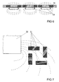
- FIG. 6 shows several, uniformly magnetized detector elements 29 for use in the detectors 14, 19 after the FIGS. 1 to 4 , These detector elements 29 are in a row arranged at a designated distance from each other and each generate dashed lines shown field lines.
- the magnetization and the dimensions of the detector elements 29 form a magnetic pattern, which can be detected by different discoloration of a ferrofluid film 30. Again, a strong magnetic field leads to a magnetization of the detector elements 29 and thus to a destruction of the pattern, as in FIG. 5c is shown.
- FIG. 7 shows a plurality of detector elements 31, arranged in a predetermined pattern, which are intended for use in the detectors 14, 19 according to FIGS FIGS. 1 to 4 can be used when a strong magnetic field of a magnet 32.
- the field lines of the magnet 32 are shown in dashed lines and generate a magnetization in the detector elements 31, which is illustrated for simplicity by a different hatching.
- the detector elements 31 may be unmagnetized. If the unmagnetized detector elements 31 are exposed to a strong magnetic field of the magnet 32 during the manipulation attempt, this manipulation attempt can be detected by the presence of the hatched magnetization.
Landscapes
- Physics & Mathematics (AREA)
- Engineering & Computer Science (AREA)
- Electromagnetism (AREA)
- Computer Security & Cryptography (AREA)
- General Physics & Mathematics (AREA)
- Theoretical Computer Science (AREA)
- Burglar Alarm Systems (AREA)
- Geophysics And Detection Of Objects (AREA)
- Credit Cards Or The Like (AREA)
- Lock And Its Accessories (AREA)
Description
- Die Erfindung betrifft eine Kombination eines Schließzylinders mit einem magnetisch aktivierbaren Sperrmechanismus und einer Vorrichtung zum Nachweis eines Manipulationsversuches mit einem starken äußeren Magnetfeld.
- Schließzylinder mit einem magnetisch aktivierbaren Sperrmechanismus sind beispielsweise aus der
DE 199 01 838 A1 bekannt. Bei diesem Schließzylinder ist ein Sperrriegel in einer Bohrung des Gehäuses verschieblich angeordnet und wird von einem Federelement in Richtung Kern vorgespannt. Der Kern weist Taschen zur Aufnahme des Sperrriegels auf. In Grundstellung des Schließzylinders wird ein mit dem Sperrriegel verbundener Anker gegen einen Elektromagneten des elektromagnetisch aktivierbaren Sperrmechanismus gedrückt. Bei einer vorliegenden Schließberechtigung wird der Elektromagnet bestromt und hält den Anker. Damit wird der Sperrriegel innerhalb des Gehäuses gehalten, und der Kern kann gegenüber dem Gehäuse verdreht werden. Bei fehlender Schließberechtigung wird der Sperrmechanismus nicht bestromt und der Sperrriegel gelangt durch die Kraft des Federelementes bei einer Drehung des Kerns in eine der Taschen des Kerns und blockiert dessen weitere Bewegung. Der magnetisch aktivierbare Sperrmechanismus weist in der Regel hochpermeable, ferromagnetische Werkstoffe mit kleiner Koerzitivfeldstärke auf. Ein solcher Sperrmechanismus ist jedoch anfällig gegenüber starken magnetischen Störfeldern, welche beispielsweise bei einem Manipulationsversuch mit einem starken Magneten eingesetzt werden könnten. - Aus der
DE 102 30 344 B3 ist eine Elektromagnetanordnung bekannt geworden, bei der magnetische Sicherheitsmittel auf ein magnetisches Fremdfeld ansprechen und die Bewegung einer Kupplung in eine Schaltposition verhindern sollen. - Aus der
US 2002/0149197 A1 ist ein Detektor zur Anzeige des Status von elektromagnetischen Sicherheitsetiketten bekannt geworden. Die Sicherheitsetiketten weisen in Abhängigkeit von unterschiedlichen Magnetfeldern unterschiedliche Muster auf. - Aus der
WO 03/061960 A1 - Mit heutigen Selten-Erden-Dauermagneten können jedoch sehr große Störfelder im Bereich bis zu einem Tesla im Abstand von einigen Zentimetern erzeugt werden. Solche Felder lassen sich oft, bedingt durch die Bauart oder die Einbauposition des magnetisch aktivierbaren Sperrmechanismus nicht zuverlässig abschirmen, da zur Abschirmung eingesetzte ferromagnetische Materialien durch solche Störfelder magnetisch in Sättigung gebracht werden können.
- Daher ist es häufig wünschenswert, einen Nachweis über eine versuchte Manipulation des Schließzylinders mit einem starken magnetischen Störfeld zu führen. Der Nachweis sollte dabei bereits unterhalb jener Feldstärke ansprechen, bei welcher der Sperrmechanismus beeinflusst wird und anderseits einen entsprechenden Abstand zu in der Umgebung allgemein vorherrschenden magnetischen Feldern aufweisen.
- Der Erfindung liegt daher das Problem zugrunde, eine Kombination eines Schließzylinders mit einem magnetisch aktivierbaren sperrmechanismus und einer Vorrichtung zu schaffen, mit der ein Nachweis eines Manipulationsversuch zu erbringen ist.
- Dieses Problem wird erfindungsgemäß durch die Merkmale des Anspruchs 1 gelöst.
- Durch diese Gestaltung kann ein ausreichend starkes Magnetfeld zu der Zerstörung des magnetischen Musters des Detektors führen. Zur Erzeugung des Musters kann beispielsweise das Detektorelement das Muster selbst aufweisen. Bei einem ausreichend starken äußeren Magnetfeld kann das Detektorelement ummagnetisiert und damit das Muster zerstört werden. Weiterhin kann das Detektorelement im entmagnetisierten Zustand eingesetzt werden und von dem starken äußeren Magnetfeld in irgendeiner Weise magnetisiert werden. Als Detektor geeignete Werkstoffe sind beispielsweise Eisen-Chrom-Kobalt-Nickel-Legierungen mit Koerzitivfeldstärke im Bereich von 1 bis 60 kA/m und sind unter den Handelsnamen Magnetoflex, Sensorvac oder Semivac bekannt. Die Werkstoffe können durch weitere Zusatzelemente sowie die Verarbeitung durch beispielsweise Glühen auf einen vorgesehenen Wert der Koerzitivfeldstärke eingestellt werden, so dass am dem Sperrmechanismus des Schließzylinders nahen Einbauort des Detektors eine Störfeldstärke bereits unterhalb der zur Manipulation erforderlichen Feldstärke erfasst werden kann. Die genannten Materialien besitzen eine im Wesentlichen rechteckförmige Magnetisierungsschleife, die so genannte b-h-Kennlinie. Der Nachweis des Manipulationsversuchs mit dem starken äußeren Magnetfeld kann durch die Änderung der Magnetisierung des Detektors nach Betrag und Richtung erfolgen, welche das Magnetfeld hervorruft. Das magnetische Muster im unveränderten Zustand und im von dem äußeren starken Magnetfeld veränderten Zustand kann beispielsweise mit einem Hallsensor oder mit einem sogenannten magnetischen Auge nachgewiesen werden. Ebenso kann der Nachweis optisch über spezielle Ferrofluidfolien erfolgen. Wird eine solche Ferrofluidfolie auf den Detektor aufgebracht, so reichern sich die in einer darin befindlichen Flüssigkeit suspendierten magnetischen Teilchen im Bereich großer magnetischer Feldstärken an und führen zu einer Verfärbung in Abhängigkeit von den unterschiedlichen Feldstärken des Detektors. Weiterhin kann der Nachweis auch durch magneto-optisch aktive Schichten erfolgen, deren optische Eigenschaften, wie beispielsweise der Brechungsindex, von der vorhandenen Magnetfeldstärke abhängt. Durch eine Beleuchtung mit polarisiertem Licht kann indirekt das Magnetfeld sichtbar gemacht werden.
- Die Montage des Detektorelementes erfordert gemäß einer vorteilhaften Weiterbildung der Erfindung einen besonders geringen Aufwand, wenn das Detektorelement als Detektorfolie ausgebildet ist. Die vorstehend genannten Materialien eignen sich durch ihre gute Kaltverformbarkeit zur Erzeugung von Folien vorzugsweise in einem Dickenbereich unter 100 µm und sind gegen mechanische Beanspruchung weitgehend unempfindlich.
- Der Detektor weist gemäß einer anderen vorteilhaften Weiterbildung der Erfindung eine hohe Stabilität auf, wenn das Detektorelement als Stift oder Platte ausgebildet ist.
- Vorhandene Schließanlagen lassen sich mit der erfindungsgemäßen Vorrichtung einfach nachrüsten, wenn das Detektorelement an dem Schließzylinder, im Bereich eines den Schließzylinder aufnehmenden Schlosskastens oder einer den Schließzylinder umschließenden Rosette angeordnet ist.
- Das Detektorelement trägt gemäß einer anderen vorteilhaften Weiterbildung der Erfindung zum Schutz des Schließzylinders gegen ein Aufbohren bei, wenn das Detektorelement im Gehäuse zwischen der Stirnseite und dem Sperrmechanismus angeordnet ist. Hierfür können beispielsweise als Detektorelement ausgebildete Stifte anstelle allgemein bekannter Bohrschutzstifte in das Gehäuse des Schließzylinders eingepresst werden. Damit ist der Detektor als Bohrschutzelement ausgebildet.
- Der Nachweis des Manipulationsversuchs gestaltet sich gemäß einer anderen vorteilhaften Weiterbildung der Erfindung besonders einfach, wenn das Detektorelement eine magneto-optische Oberfläche aufweist und an einem von au-ßerhalb des Schließzylinders sichtbaren Bereich angeordnet ist.
- Der Detektor gestaltet sich gemäß einer anderen vorteilhaften Weiterbildung der Erfindung konstruktiv besonders einfach, wenn das magnetische Muster des Detektors in dem Detektorelement angeordnet ist.
- Das vorgesehene Musters lässt sich gemäß einer anderen vorteilhaften Weiterbildung der Erfindung durch eine Anordnung von mehreren, verteilt angeordneten Detektorelementen mit einer vorgesehenen magnetischen Ausrichtung besonders einfach zusammenstellen. Hierdurch kann das magnetische Muster des Detektors von den selbst eine magnetische Ausrichtung aufweisenden Detektorelementen gebildet werden. Weisen beispielsweise zwei nebeneinander angeordnete Detektorelemente einander gegensinnige magnetische Ausrichtungen auf, werden die Ausrichtungen bei einem äußeren Magnetfeld beispielsweise ummagnetisiert, so dass sie gleichsinnig ausgerichtet sind. Damit werden bei der Einwirkung des starken Magnetfeldes die magnetischen Ausrichtungen der Detektorelemente geändert, womit sich ein Manipulationsversuch erfassen lässt.
- Zur Erhöhung der Zuverlässigkeit der Erfassung eines Manipulationsversuchs trägt es gemäß einer anderen vorteilhaften Weiterbildung der Erfindung bei, wenn mehrere Detektorelemente in einer Reihe angeordnet sind. Das magnetische Muster des Detektors kann dabei von den einzelnen Detektorelementen zusammengesetzt werden.
- Die Erfindung lässt zahlreiche Ausführungsformen zu. Zur Verdeutlichung ihres Grundprinzips sind mehrere davon in der Zeichnung dargestellt und werden nachfolgend beschrieben. Diese zeigt in
- Fig. 1
- ein Beispiel einer erfindungsgemäßen Vorrichtung an einem in einer Tür angeordneten Schließzylinder im Längsschnitt,
- Fig. 2
- eine Draufsicht auf eine Stirnseite des Schließzylinders aus
Figur 1 mit angrenzenden Bereichen der einer Rosette, - Fig. 3
- einen Schließzylinder mit einer weiteren Ausführungsform der erfindungsgemäßen Vorrichtung,
- Fig. 4
- eine Draufsicht auf eine Stirnseite des Schließzylinders aus
Figur 3 , - Fig.5a - 5c
- verschiedene Ansichten eines Beispiels eines Detektors der erfindungsgemäßen Vorrichtung,
- Fig. 6
- eine weitere Ausführungsform des Detektors mit mehreren Detektorelementen,
- Fig. 7
- eine weitere Ausführungsform des Detektors bei einer Einwirkung eines äußeren Magnetfeldes.
-
Figur 1 zeigt schematisch einen in einer Tür 1 angeordneten Schlosskasten 2 mit einem darin befestigten Schließzylinder 3 und mit einer Vorrichtung 4 zum Nachweis eines Manipulationsversuches. Der Schließzylinder 3 hat einen in einem Gehäuse 5 drehbaren Kern 6 und einen elektromagnetisch aktivierbaren Sperrmechanismus 7. Der elektromagnetisch aktivierbare Sperrmechanismus 7 steuert die Bewegbarkeit des Kerns 6 gegenüber dem Gehäuse 5 in Abhängigkeit eines in einen Schließkanal 8 des Kerns 6 eingeführten Schlüssels. Er kann alternativ auch als Kupplung ausgeführt sein. Der Sperrmechanismus 7 weist einen in eine Ausnehmung 9 des Kerns 6 eindringenden Sperrriegel 10 und einen Elektromagneten 11 zur Steuerung der Bewegbarkeit des Sperrriegels 10 auf und ist in derDE 199 01 838 A1 ausführlich beschrieben. Daher wird für die Offenbarung der Bauteile und der Funktion des Sperrmechanismus 7 ausdrücklich auf diese Schrift verwiesen. Die über der Tür 1 überstehende Stirnseite des Schließzylinders 3 ist mit einer Rosette 12 umgeben. Der Kern 6 des Schließzylinders 3 ist mit einem Schließbart 13 drehfest verbunden. Die Vorrichtung 4 zur Erfassung eines Manipulationsversuchs weist einen Detektor 14 mit einem einzelnen, auf der Außenseite des Schließzylinders 3 angeordneten Detektorelement 15 auf. Das Detektorelement 15 ist als Folie ausgebildet und weist ein magnetisches Muster, beispielsweise eine bereichsweise alternierende magnetische Polung auf und ist im Wesentlichen zwischen dem Sperrmechanismus 7 und der über der Tür 1 überstehenden Stirnseite des Schließzylinders 3 angeordnet. Wenn man versucht, den Sperrmechanismus 7 mittels eines starken Magnetfeldes eines vor die Tür 1 gehaltenen Magneten 16 zu manipulieren, wird das magnetische Muster des Detektorelementes 15 von dem Magneten 16 zerstört. Dieser Manipulationsversuch ist durch Messung des Musters des Detektorelementes 15 erfassbar. -
Figur 2 zeigt den Schließzylinder 3 ausFigur 1 mit der Rosette 12 in einer Ansicht auf seine über der Tür 1 überstehenden Stirnseite. In einer weiteren, nicht dargestellten Ausführungsform kann der Detektor 14 auch mehrere Detektorelemente 15 aufweisen oder auf der Rosette 12 sichtbar oder unsichtbar angeordnet sein. Denkbar ist ebenfalls die Anordnung des Detektors 14 auf dem Schlosskasten 2 oder auf der Tür 1. -
Figur 3 zeigt einen Schließzylinder 17 mit einem mehrere Detektorelemente 18 aufweisenden Detektor 19. Die Detektorelemente 18 sind in einem Gehäuse 20 und in einem Kern des Schließzylinders 17 angeordnet. Die Detektorelemente 18 sind als Stifte ausgebildet und können zur Erzeugung des magnetischen Musters eine unterschiedliche Ausrichtung ihrer Magnetpole aufweisen. Bei einem starken äußeren Magnetfeld wird die Ausrichtung der Magnetpole der Detektorelemente 18 geändert und kann einfach, beispielsweise durch Hallelemente nachgewiesen werden. Einige der Detektorelemente 18 sind in das Gehäuse 20 zwischen einem magnetisch aktivierbaren Sperrmechanismus 22 und einer Stirnseite eingepresst und können zudem als Bohrschutz dienen. Zur Verdeutlichung zeigtFigur 4 den Schließzylinder 17 ausFigur 3 in einer Ansicht auf die Stirnseite. Hierbei ist zu erkennen, dass die in dem Kern 21 angeordneten Detektorelemente 18 um einen Schließkanal 23 herum gruppiert sind und ebenfalls einen Schutz gegen ein Aufbohren bieten. -
Figur 5a zeigt ein Detektorelement 24 für den Einsatz in den Detektoren 14, 19 aus denFiguren 1 bis 4 während der Erzeugung eines magnetischen Musters. Hierfür wird ein zur Erzeugung des magnetischen Musters vorgesehener Stempel 25 mit einer Rückschlussplatte 26 und darauf angeordneten Permanentmagneten 27 mit unterschiedlichen Magnetisierungsrichtungen eingesetzt. Die Magnetpole der Permanentmagnete 27 wechseln einander ab, so dass abwechselnd der Nordpol oder der Südpol der Permanentmagnete 27 von der Rückschlussplatte 26 weg auf das Detektorelement 24 weist. Hierbei wird das Detektorelement 24 mit einem magnetischen Muster versehen, welches beispielsweise mittels einer auf das Detektorelement 24 aufgelegten und inFigur 5b dargestellten Ferrofluidfolie 28 nachgewiesen werden kann. Die Ferrofluidfolie 28 macht das mit dem Stempel 25 erzeugte magnetische Muster durch eine unterschiedliche Verfärbung sichtbar, welche in der Zeichnung durch eine unterschiedliche Schraffur veranschaulicht ist. Bei einem Manipulationsversuch mit einem starken Magnetfeld wird das mit dem Stempel 25 erzeugte magnetische Muster zerstört, so dass die auf das Detektorelement 24 aufgelegte Ferrofluidfolie 28 eine deutlich andere Verfärbung zeigt, wie es inFigur 5c dargestellt ist. -
Figur 6 zeigt mehrere, einheitlich magnetisierte Detektorelemente 29 zum Einsatz in den Detektoren 14, 19 nach denFiguren 1 bis 4 . Diese Detektorelemente 29 sind in einer Reihe auf einem vorgesehenen Abstand zueinander angeordnet und erzeugen jeweils gestrichelt dargestellte Feldlinien. Die Magnetisierung und die Abmessungen der Detektorelemente 29 bilden ein magnetisches Muster, welches durch unterschiedliche Verfärbungen einer Ferrofluidfolie 30 nachgewiesen werden kann. Auch hier führt ein starkes Magnetfeld zu einer Aufmagnetisierung der Detektorelemente 29 und damit zu einer Zerstörung des Musters, wie es inFigur 5c dargestellt ist. -
Figur 7 zeigt mehrere, in einem vorgesehenen Muster angeordnete Detektorelemente 31, welche zum Einsatz in den Detektoren 14, 19 nach denFiguren 1 bis 4 eingesetzt werden können, bei der Einwirkung eines starken Magnetfeldes eines Magneten 32. Die Feldlinien des Magneten 32 sind gestrichelt dargestellt und erzeugen eine Magnetisierung in den Detektorelementen 31, welche zur Vereinfachung durch eine unterschiedliche Schraffur veranschaulicht ist. Im Grundzustand können die Detektorelemente 31 unmagnetisiert sein. Werden die unmagnetisierten Detektorelemente 31 beim Manipulationsversuch einem starken Magnetfeld des Magneten 32 ausgesetzt, lässt sich dieser Manipulationsversuch an dem Vorhandensein der schraffiert dargestellten Magnetisierung erkennen.
Claims (9)
- Kombination eines Schließzylinders (3, 17) mit einem magnetisch aktivierbaren Sperrmechanismus (7, 22) und einer Vorrichtung (4) zum Nachweis eines Manipulationsversuches mit einem starken äußeren Magnetfeld, bei der ein Detektor (14, 19) an dem Schließzylinder (3, 17) oder in der unmittelbaren Umgebung des Schließzylinders (3, 17) anordenbar ist und der Detektor (14, 19) zumindest ein aus einem halbharten magnetischen Material gefertigtes Detektorelement (15, 18, 24, 29, 31) und ein magnetisches Muster aufweist wobei sich das magnetische Muster von einem von einem solchen starken äußeren Magnetfeld erzeugten Muster unterscheidet.
- Kombination nach Anspruch 1, dadurch gekennzeichnet, dass das Detektorelement (15, 24, 29, 31) als Detektorfolie ausgebildet ist.
- Kombination nach Anspruch 1, dadurch gekennzeichnet, dass das Detektorelement (18, 24, 29, 31) als Stift oder Platte ausgebildet ist.
- Kombination nach einem der Ansprüche 1 bis 3, dadurch gekennzeichnet, dass das Detektorelement (15, 18, 24, 29, 31) an dem Schließzylinder (3, 17), im Bereich eines den Schließzylinder (3, 17) aufnehmenden Schlosskastens (2) oder einer den Schließzylinder (3, 17) umschließenden Rosette (12) anordenbar ist.
- Kombination nach einem der Ansprüche 1 bis 3, dadurch gekennzeichnet, dass das Detektorelement (15, 18, 24, 29, 31) im Gehäuse (5, 20) des Schlißzylinders zwischen der Stirnseite des Schlißzylinders und dem Sperrmechanismus (7, 22) angeordnet ist.
- Kombination nach einem der Ansprüche 1 bis 3, dadurch gekennzeichnet, dass das Detektorelement (24, 29, 31) eine magneto-optische Oberfläche aufweist und an einem von außerhalb des Schließzylinders (3, 17) sichtbaren Bereich angeordnet ist.
- Kombination nach Anspruch 1, dadurch gekennzeichnet, dass das magnetische Muster des Detektors (14, 19) in dem Detektorelement (15, 18, 24, 29, 31) angeordnet ist.
- Kombination nach Anspruch 1, gekennzeichnet durch eine Anordnung von mehreren, verteilt angeordneten Detektorelementen (18, 24, 29, 31) mit einer vorgesehenen magnetischen Ausrichtung.
- Kombination nach Anspruch 1, dadurch gekennzeichnet, dass mehrere Detektorelemente (29) in einer Reihe angeordnet sind.
Priority Applications (1)
| Application Number | Priority Date | Filing Date | Title |
|---|---|---|---|
| PL05110770T PL1672152T3 (pl) | 2004-12-14 | 2005-11-15 | Zespół bębenka zamkowego i urządzenie do wykrywania próby manipulacji |
Applications Claiming Priority (1)
| Application Number | Priority Date | Filing Date | Title |
|---|---|---|---|
| DE102004060430A DE102004060430A1 (de) | 2004-12-14 | 2004-12-14 | Vorrichtung zum Nachweis eines Manipulationsversuches |
Publications (3)
| Publication Number | Publication Date |
|---|---|
| EP1672152A2 EP1672152A2 (de) | 2006-06-21 |
| EP1672152A3 EP1672152A3 (de) | 2006-08-02 |
| EP1672152B1 true EP1672152B1 (de) | 2008-02-27 |
Family
ID=36102998
Family Applications (1)
| Application Number | Title | Priority Date | Filing Date |
|---|---|---|---|
| EP05110770A Expired - Lifetime EP1672152B1 (de) | 2004-12-14 | 2005-11-15 | Kombination eines Schliesszylinders und einer Vorrichtung zum Nachweis eines Manipulationsversuches |
Country Status (5)
| Country | Link |
|---|---|
| EP (1) | EP1672152B1 (de) |
| AT (1) | ATE387556T1 (de) |
| DE (2) | DE102004060430A1 (de) |
| ES (1) | ES2300941T3 (de) |
| PL (1) | PL1672152T3 (de) |
Families Citing this family (1)
| Publication number | Priority date | Publication date | Assignee | Title |
|---|---|---|---|---|
| CN113219383B (zh) * | 2021-05-25 | 2022-12-06 | 韩山师范学院 | 一种磁场的测量装置 |
Family Cites Families (12)
| Publication number | Priority date | Publication date | Assignee | Title |
|---|---|---|---|---|
| DE1766972A1 (de) * | 1967-08-22 | 1971-09-16 | Nat Res Dev | Verfahren zum Pruefen von Proben eines ferromagnetischen Materials und Einrichtung zum Durchfuehren des Verfahrens |
| DE2037077A1 (de) * | 1970-07-27 | 1972-02-03 | Springer G | Verfahren zur räumlichen Sichtbar machung und Fixierung von magnetischen und elektrischen Feldern |
| US4077242A (en) * | 1976-12-15 | 1978-03-07 | Sedley Bruce S | Metal magnetic key |
| AT379427B (de) * | 1984-01-24 | 1986-01-10 | Grundmann Gmbh Geb | Magnetschluessel |
| DE4317995A1 (de) * | 1993-05-28 | 1994-12-01 | Winkhaus Fa August | Schließzylinder mit Aufbohrschutzeinrichtung |
| DE4323883C2 (de) * | 1993-07-16 | 2002-11-07 | Meto International Gmbh | Diebstahlsicherungsetikett |
| DE29823931U1 (de) * | 1998-09-10 | 2000-03-23 | Dorma Gmbh + Co. Kg, 58256 Ennepetal | Schloß mit alarmauslösender Zuhaltevorrichtung |
| DE19901838A1 (de) * | 1999-01-19 | 2000-07-20 | Winkhaus Fa August | Elektromagnetisch aktivierbarer Sperrmechanismus |
| DE19958466A1 (de) * | 1999-12-04 | 2001-06-07 | Meto International Gmbh | Vorrichtung und Verfahren zum Anzeigen des Zustands von EM- oder AM-Sicherungsetiketten |
| US6474122B2 (en) * | 2000-01-25 | 2002-11-05 | Videx, Inc. | Electronic locking system |
| WO2003061960A1 (en) * | 2002-01-23 | 2003-07-31 | Perm-A-Store, Inc. | Marker for indicating degaussing of magnetic storage devices |
| DE10230344B3 (de) * | 2002-07-03 | 2004-01-22 | Dom-Sicherheitstechnik Gmbh & Co. Kg | Manipulationssichere Elektromagnetanordnung, elektronischer Schließzylinder und Verfahren zum Verhindern einer Manipulation einer Elektromagnetanordnung |
-
2004
- 2004-12-14 DE DE102004060430A patent/DE102004060430A1/de not_active Withdrawn
-
2005
- 2005-11-15 DE DE502005002975T patent/DE502005002975D1/de not_active Expired - Lifetime
- 2005-11-15 PL PL05110770T patent/PL1672152T3/pl unknown
- 2005-11-15 EP EP05110770A patent/EP1672152B1/de not_active Expired - Lifetime
- 2005-11-15 AT AT05110770T patent/ATE387556T1/de active
- 2005-11-15 ES ES05110770T patent/ES2300941T3/es not_active Expired - Lifetime
Also Published As
| Publication number | Publication date |
|---|---|
| EP1672152A3 (de) | 2006-08-02 |
| ATE387556T1 (de) | 2008-03-15 |
| EP1672152A2 (de) | 2006-06-21 |
| DE502005002975D1 (de) | 2008-04-10 |
| PL1672152T3 (pl) | 2008-07-31 |
| ES2300941T3 (es) | 2008-06-16 |
| DE102004060430A1 (de) | 2006-06-22 |
Similar Documents
| Publication | Publication Date | Title |
|---|---|---|
| DE3148644C2 (de) | ||
| DE69431458T2 (de) | Echtheitsüberprüfung von Gegenständen | |
| EP1378620A2 (de) | Manipulationssichere Elektromagnetanordnung, elektronischer Schliesszylinder und Verfahren zum Verhindern einer Manipulation einer Elektromagnetanordnung | |
| EP0276444B1 (de) | Schliesseinrichtung mit grosser Schliesskombinationsanzahl | |
| EP2711905B1 (de) | Meldesystem | |
| WO2008074642A1 (de) | SCHLIEßZYLINDER MIT DURCH MAGNETKRAFT VERLAGERBAREM ZUHALTUNGSSTIFT UND ZUGEHÖRIGER SCHLÜSSEL | |
| CH649855A5 (de) | Einrichtung an schloessern zur verhinderung eines unbefugten zugangs. | |
| EP1618006B1 (de) | Sicherheitselement und prüfverfahren für ein wertdokument | |
| DE29823167U1 (de) | Warensicherungselement | |
| DE19901838A1 (de) | Elektromagnetisch aktivierbarer Sperrmechanismus | |
| EP0244652B1 (de) | Blockschloss | |
| EP1672152A2 (de) | Vorrichtung zum Nachweis eines Manipulationsversuches | |
| EP3162988B1 (de) | Schliessvorrichtung für eine tür | |
| DE4422094C2 (de) | Schloß für Türen | |
| DE19907716A1 (de) | Gurtschloß mit Hall-Sensor | |
| DE10246642B4 (de) | Elektromechanisches Schloss mit Schutz gegen Manipulation | |
| AT398803B (de) | Sperr- und überwachungsvorrichtung für safes, insbesondere schliessfachanlagen | |
| DE69328819T2 (de) | Doppelstatus-Dünnfilmmarkierung für elektronische Artikelüberwachung | |
| DE202004016988U1 (de) | Vorrichtung zur Sicherung eines durch eine drehbare Schließnase betätigten Schließmechanismus gegen magnetische Manipulation | |
| DE3819955A1 (de) | Schliesseinrichtung mit schluesselcodiertem druckeranschluss | |
| DE202007003197U1 (de) | Elektrische Verriegelungsvorrichtung für ein Schloss | |
| EP1977403B1 (de) | Warensicherungselement für akustomagnetische sicherungssysteme | |
| DE8530957U1 (de) | Magnetfeldbetätigte Sicherheits-Kontakteinrichtung | |
| EP0845565A1 (de) | Sicherheitsschloss | |
| DE951425C (de) | Vorrichtung zum Erleichtern des Einfuehrens eines ferromagnetischen Werkzeugs in eine OEffnung |
Legal Events
| Date | Code | Title | Description |
|---|---|---|---|
| PUAI | Public reference made under article 153(3) epc to a published international application that has entered the european phase |
Free format text: ORIGINAL CODE: 0009012 |
|
| AK | Designated contracting states |
Kind code of ref document: A2 Designated state(s): AT BE BG CH CY CZ DE DK EE ES FI FR GB GR HU IE IS IT LI LT LU LV MC NL PL PT RO SE SI SK TR |
|
| AX | Request for extension of the european patent |
Extension state: AL BA HR MK YU |
|
| PUAL | Search report despatched |
Free format text: ORIGINAL CODE: 0009013 |
|
| AK | Designated contracting states |
Kind code of ref document: A3 Designated state(s): AT BE BG CH CY CZ DE DK EE ES FI FR GB GR HU IE IS IT LI LT LU LV MC NL PL PT RO SE SI SK TR |
|
| AX | Request for extension of the european patent |
Extension state: AL BA HR MK YU |
|
| 17P | Request for examination filed |
Effective date: 20061129 |
|
| AKX | Designation fees paid |
Designated state(s): AT BE BG CH CY CZ DE DK EE ES FI FR GB GR HU IE IS IT LI LT LU LV MC NL PL PT RO SE SI SK TR |
|
| RTI1 | Title (correction) |
Free format text: LOCK CYLINDER WITH A DEVICE FOR DETECTING TAMPERING |
|
| RTI1 | Title (correction) |
Free format text: COMBINATION OF A LOCK CYLINDER AND A DEVICE FOR DETECTING TAMPERING |
|
| GRAP | Despatch of communication of intention to grant a patent |
Free format text: ORIGINAL CODE: EPIDOSNIGR1 |
|
| GRAS | Grant fee paid |
Free format text: ORIGINAL CODE: EPIDOSNIGR3 |
|
| GRAA | (expected) grant |
Free format text: ORIGINAL CODE: 0009210 |
|
| AK | Designated contracting states |
Kind code of ref document: B1 Designated state(s): AT BE BG CH CY CZ DE DK EE ES FI FR GB GR HU IE IS IT LI LT LU LV MC NL PL PT RO SE SI SK TR |
|
| REG | Reference to a national code |
Ref country code: GB Ref legal event code: FG4D Free format text: NOT ENGLISH |
|
| REG | Reference to a national code |
Ref country code: CH Ref legal event code: EP Ref country code: CH Ref legal event code: NV Representative=s name: E. BLUM & CO. AG PATENT- UND MARKENANWAELTE VSP |
|
| REG | Reference to a national code |
Ref country code: IE Ref legal event code: FG4D Free format text: LANGUAGE OF EP DOCUMENT: GERMAN |
|
| REF | Corresponds to: |
Ref document number: 502005002975 Country of ref document: DE Date of ref document: 20080410 Kind code of ref document: P |
|
| REG | Reference to a national code |
Ref country code: DE Ref legal event code: R096 Ref document number: 502005002975 Country of ref document: DE Effective date: 20080410 |
|
| REG | Reference to a national code |
Ref country code: ES Ref legal event code: FG2A Ref document number: 2300941 Country of ref document: ES Kind code of ref document: T3 |
|
| PG25 | Lapsed in a contracting state [announced via postgrant information from national office to epo] |
Ref country code: IS Free format text: LAPSE BECAUSE OF FAILURE TO SUBMIT A TRANSLATION OF THE DESCRIPTION OR TO PAY THE FEE WITHIN THE PRESCRIBED TIME-LIMIT Effective date: 20080627 Ref country code: FI Free format text: LAPSE BECAUSE OF FAILURE TO SUBMIT A TRANSLATION OF THE DESCRIPTION OR TO PAY THE FEE WITHIN THE PRESCRIBED TIME-LIMIT Effective date: 20080227 |
|
| REG | Reference to a national code |
Ref country code: PL Ref legal event code: T3 |
|
| PG25 | Lapsed in a contracting state [announced via postgrant information from national office to epo] |
Ref country code: SI Free format text: LAPSE BECAUSE OF FAILURE TO SUBMIT A TRANSLATION OF THE DESCRIPTION OR TO PAY THE FEE WITHIN THE PRESCRIBED TIME-LIMIT Effective date: 20080227 Ref country code: LV Free format text: LAPSE BECAUSE OF FAILURE TO SUBMIT A TRANSLATION OF THE DESCRIPTION OR TO PAY THE FEE WITHIN THE PRESCRIBED TIME-LIMIT Effective date: 20080227 |
|
| REG | Reference to a national code |
Ref country code: IE Ref legal event code: FD4D |
|
| ET | Fr: translation filed | ||
| PG25 | Lapsed in a contracting state [announced via postgrant information from national office to epo] |
Ref country code: SK Free format text: LAPSE BECAUSE OF FAILURE TO SUBMIT A TRANSLATION OF THE DESCRIPTION OR TO PAY THE FEE WITHIN THE PRESCRIBED TIME-LIMIT Effective date: 20080227 Ref country code: SE Free format text: LAPSE BECAUSE OF FAILURE TO SUBMIT A TRANSLATION OF THE DESCRIPTION OR TO PAY THE FEE WITHIN THE PRESCRIBED TIME-LIMIT Effective date: 20080527 Ref country code: CZ Free format text: LAPSE BECAUSE OF FAILURE TO SUBMIT A TRANSLATION OF THE DESCRIPTION OR TO PAY THE FEE WITHIN THE PRESCRIBED TIME-LIMIT Effective date: 20080227 Ref country code: PT Free format text: LAPSE BECAUSE OF FAILURE TO SUBMIT A TRANSLATION OF THE DESCRIPTION OR TO PAY THE FEE WITHIN THE PRESCRIBED TIME-LIMIT Effective date: 20080721 Ref country code: DK Free format text: LAPSE BECAUSE OF FAILURE TO SUBMIT A TRANSLATION OF THE DESCRIPTION OR TO PAY THE FEE WITHIN THE PRESCRIBED TIME-LIMIT Effective date: 20080227 Ref country code: IE Free format text: LAPSE BECAUSE OF FAILURE TO SUBMIT A TRANSLATION OF THE DESCRIPTION OR TO PAY THE FEE WITHIN THE PRESCRIBED TIME-LIMIT Effective date: 20080227 |
|
| PG25 | Lapsed in a contracting state [announced via postgrant information from national office to epo] |
Ref country code: RO Free format text: LAPSE BECAUSE OF FAILURE TO SUBMIT A TRANSLATION OF THE DESCRIPTION OR TO PAY THE FEE WITHIN THE PRESCRIBED TIME-LIMIT Effective date: 20080227 |
|
| PLBE | No opposition filed within time limit |
Free format text: ORIGINAL CODE: 0009261 |
|
| STAA | Information on the status of an ep patent application or granted ep patent |
Free format text: STATUS: NO OPPOSITION FILED WITHIN TIME LIMIT |
|
| PG25 | Lapsed in a contracting state [announced via postgrant information from national office to epo] |
Ref country code: LT Free format text: LAPSE BECAUSE OF FAILURE TO SUBMIT A TRANSLATION OF THE DESCRIPTION OR TO PAY THE FEE WITHIN THE PRESCRIBED TIME-LIMIT Effective date: 20080227 |
|
| 26N | No opposition filed |
Effective date: 20081128 |
|
| REG | Reference to a national code |
Ref country code: DE Ref legal event code: R097 Ref document number: 502005002975 Country of ref document: DE Effective date: 20081128 |
|
| PG25 | Lapsed in a contracting state [announced via postgrant information from national office to epo] |
Ref country code: EE Free format text: LAPSE BECAUSE OF FAILURE TO SUBMIT A TRANSLATION OF THE DESCRIPTION OR TO PAY THE FEE WITHIN THE PRESCRIBED TIME-LIMIT Effective date: 20080227 Ref country code: BG Free format text: LAPSE BECAUSE OF FAILURE TO SUBMIT A TRANSLATION OF THE DESCRIPTION OR TO PAY THE FEE WITHIN THE PRESCRIBED TIME-LIMIT Effective date: 20080527 |
|
| PG25 | Lapsed in a contracting state [announced via postgrant information from national office to epo] |
Ref country code: MC Free format text: LAPSE BECAUSE OF NON-PAYMENT OF DUE FEES Effective date: 20081130 |
|
| PG25 | Lapsed in a contracting state [announced via postgrant information from national office to epo] |
Ref country code: CY Free format text: LAPSE BECAUSE OF FAILURE TO SUBMIT A TRANSLATION OF THE DESCRIPTION OR TO PAY THE FEE WITHIN THE PRESCRIBED TIME-LIMIT Effective date: 20080227 |
|
| PG25 | Lapsed in a contracting state [announced via postgrant information from national office to epo] |
Ref country code: IT Free format text: LAPSE BECAUSE OF FAILURE TO SUBMIT A TRANSLATION OF THE DESCRIPTION OR TO PAY THE FEE WITHIN THE PRESCRIBED TIME-LIMIT Effective date: 20080227 |
|
| PG25 | Lapsed in a contracting state [announced via postgrant information from national office to epo] |
Ref country code: LU Free format text: LAPSE BECAUSE OF NON-PAYMENT OF DUE FEES Effective date: 20081115 Ref country code: HU Free format text: LAPSE BECAUSE OF FAILURE TO SUBMIT A TRANSLATION OF THE DESCRIPTION OR TO PAY THE FEE WITHIN THE PRESCRIBED TIME-LIMIT Effective date: 20080828 |
|
| PG25 | Lapsed in a contracting state [announced via postgrant information from national office to epo] |
Ref country code: TR Free format text: LAPSE BECAUSE OF FAILURE TO SUBMIT A TRANSLATION OF THE DESCRIPTION OR TO PAY THE FEE WITHIN THE PRESCRIBED TIME-LIMIT Effective date: 20080227 |
|
| PG25 | Lapsed in a contracting state [announced via postgrant information from national office to epo] |
Ref country code: GR Free format text: LAPSE BECAUSE OF FAILURE TO SUBMIT A TRANSLATION OF THE DESCRIPTION OR TO PAY THE FEE WITHIN THE PRESCRIBED TIME-LIMIT Effective date: 20080528 |
|
| PGFP | Annual fee paid to national office [announced via postgrant information from national office to epo] |
Ref country code: GB Payment date: 20131129 Year of fee payment: 9 |
|
| PGFP | Annual fee paid to national office [announced via postgrant information from national office to epo] |
Ref country code: PL Payment date: 20131031 Year of fee payment: 9 |
|
| GBPC | Gb: european patent ceased through non-payment of renewal fee |
Effective date: 20141115 |
|
| PG25 | Lapsed in a contracting state [announced via postgrant information from national office to epo] |
Ref country code: GB Free format text: LAPSE BECAUSE OF NON-PAYMENT OF DUE FEES Effective date: 20141115 |
|
| REG | Reference to a national code |
Ref country code: FR Ref legal event code: PLFP Year of fee payment: 11 |
|
| PGFP | Annual fee paid to national office [announced via postgrant information from national office to epo] |
Ref country code: CH Payment date: 20151125 Year of fee payment: 11 |
|
| PG25 | Lapsed in a contracting state [announced via postgrant information from national office to epo] |
Ref country code: PL Free format text: LAPSE BECAUSE OF NON-PAYMENT OF DUE FEES Effective date: 20141115 |
|
| PGFP | Annual fee paid to national office [announced via postgrant information from national office to epo] |
Ref country code: BE Payment date: 20151127 Year of fee payment: 11 |
|
| REG | Reference to a national code |
Ref country code: FR Ref legal event code: PLFP Year of fee payment: 12 |
|
| PG25 | Lapsed in a contracting state [announced via postgrant information from national office to epo] |
Ref country code: BE Free format text: LAPSE BECAUSE OF NON-PAYMENT OF DUE FEES Effective date: 20161130 |
|
| REG | Reference to a national code |
Ref country code: CH Ref legal event code: PL |
|
| PG25 | Lapsed in a contracting state [announced via postgrant information from national office to epo] |
Ref country code: LI Free format text: LAPSE BECAUSE OF NON-PAYMENT OF DUE FEES Effective date: 20161130 Ref country code: CH Free format text: LAPSE BECAUSE OF NON-PAYMENT OF DUE FEES Effective date: 20161130 |
|
| REG | Reference to a national code |
Ref country code: FR Ref legal event code: PLFP Year of fee payment: 13 |
|
| REG | Reference to a national code |
Ref country code: BE Ref legal event code: MM Effective date: 20161130 |
|
| PGFP | Annual fee paid to national office [announced via postgrant information from national office to epo] |
Ref country code: NL Payment date: 20181126 Year of fee payment: 14 |
|
| PGFP | Annual fee paid to national office [announced via postgrant information from national office to epo] |
Ref country code: ES Payment date: 20181218 Year of fee payment: 14 Ref country code: FR Payment date: 20181129 Year of fee payment: 14 |
|
| PGFP | Annual fee paid to national office [announced via postgrant information from national office to epo] |
Ref country code: AT Payment date: 20191121 Year of fee payment: 15 |
|
| REG | Reference to a national code |
Ref country code: NL Ref legal event code: MM Effective date: 20191201 |
|
| PG25 | Lapsed in a contracting state [announced via postgrant information from national office to epo] |
Ref country code: NL Free format text: LAPSE BECAUSE OF NON-PAYMENT OF DUE FEES Effective date: 20191201 |
|
| PG25 | Lapsed in a contracting state [announced via postgrant information from national office to epo] |
Ref country code: FR Free format text: LAPSE BECAUSE OF NON-PAYMENT OF DUE FEES Effective date: 20191130 |
|
| REG | Reference to a national code |
Ref country code: ES Ref legal event code: FD2A Effective date: 20210414 |
|
| REG | Reference to a national code |
Ref country code: AT Ref legal event code: MM01 Ref document number: 387556 Country of ref document: AT Kind code of ref document: T Effective date: 20201115 |
|
| PG25 | Lapsed in a contracting state [announced via postgrant information from national office to epo] |
Ref country code: ES Free format text: LAPSE BECAUSE OF NON-PAYMENT OF DUE FEES Effective date: 20191116 Ref country code: AT Free format text: LAPSE BECAUSE OF NON-PAYMENT OF DUE FEES Effective date: 20201115 |
|
| PGFP | Annual fee paid to national office [announced via postgrant information from national office to epo] |
Ref country code: DE Payment date: 20211122 Year of fee payment: 17 |
|
| REG | Reference to a national code |
Ref country code: DE Ref legal event code: R119 Ref document number: 502005002975 Country of ref document: DE |
|
| P01 | Opt-out of the competence of the unified patent court (upc) registered |
Effective date: 20230515 |
|
| PG25 | Lapsed in a contracting state [announced via postgrant information from national office to epo] |
Ref country code: DE Free format text: LAPSE BECAUSE OF NON-PAYMENT OF DUE FEES Effective date: 20230601 |