EP1671695B2 - Hohlfaserdialysator mit gelockten Hohlfasern - Google Patents
Hohlfaserdialysator mit gelockten Hohlfasern Download PDFInfo
- Publication number
- EP1671695B2 EP1671695B2 EP06002619.2A EP06002619A EP1671695B2 EP 1671695 B2 EP1671695 B2 EP 1671695B2 EP 06002619 A EP06002619 A EP 06002619A EP 1671695 B2 EP1671695 B2 EP 1671695B2
- Authority
- EP
- European Patent Office
- Prior art keywords
- hollow
- fibres
- curled
- fibre
- fibers
- Prior art date
- Legal status (The legal status is an assumption and is not a legal conclusion. Google has not performed a legal analysis and makes no representation as to the accuracy of the status listed.)
- Expired - Lifetime
Links
- 0 *CCC1CCCC1 Chemical compound *CCC1CCCC1 0.000 description 1
Images

Classifications
-
- B—PERFORMING OPERATIONS; TRANSPORTING
- B01—PHYSICAL OR CHEMICAL PROCESSES OR APPARATUS IN GENERAL
- B01D—SEPARATION
- B01D61/00—Processes of separation using semi-permeable membranes, e.g. dialysis, osmosis or ultrafiltration; Apparatus, accessories or auxiliary operations specially adapted therefor
- B01D61/24—Dialysis ; Membrane extraction
- B01D61/28—Apparatus therefor
-
- B—PERFORMING OPERATIONS; TRANSPORTING
- B01—PHYSICAL OR CHEMICAL PROCESSES OR APPARATUS IN GENERAL
- B01D—SEPARATION
- B01D69/00—Semi-permeable membranes for separation processes or apparatus characterised by their form, structure or properties; Manufacturing processes specially adapted therefor
- B01D69/08—Hollow fibre membranes
-
- B—PERFORMING OPERATIONS; TRANSPORTING
- B01—PHYSICAL OR CHEMICAL PROCESSES OR APPARATUS IN GENERAL
- B01D—SEPARATION
- B01D63/00—Apparatus in general for separation processes using semi-permeable membranes
- B01D63/02—Hollow fibre modules
-
- B—PERFORMING OPERATIONS; TRANSPORTING
- B01—PHYSICAL OR CHEMICAL PROCESSES OR APPARATUS IN GENERAL
- B01D—SEPARATION
- B01D63/00—Apparatus in general for separation processes using semi-permeable membranes
- B01D63/02—Hollow fibre modules
- B01D63/021—Manufacturing thereof
-
- B—PERFORMING OPERATIONS; TRANSPORTING
- B01—PHYSICAL OR CHEMICAL PROCESSES OR APPARATUS IN GENERAL
- B01D—SEPARATION
- B01D63/00—Apparatus in general for separation processes using semi-permeable membranes
- B01D63/02—Hollow fibre modules
- B01D63/031—Two or more types of hollow fibres within one bundle or within one potting or tube-sheet
-
- B—PERFORMING OPERATIONS; TRANSPORTING
- B01—PHYSICAL OR CHEMICAL PROCESSES OR APPARATUS IN GENERAL
- B01D—SEPARATION
- B01D65/00—Accessories or auxiliary operations, in general, for separation processes or apparatus using semi-permeable membranes
-
- B—PERFORMING OPERATIONS; TRANSPORTING
- B01—PHYSICAL OR CHEMICAL PROCESSES OR APPARATUS IN GENERAL
- B01D—SEPARATION
- B01D69/00—Semi-permeable membranes for separation processes or apparatus characterised by their form, structure or properties; Manufacturing processes specially adapted therefor
- B01D69/08—Hollow fibre membranes
- B01D69/084—Undulated fibres
-
- B—PERFORMING OPERATIONS; TRANSPORTING
- B01—PHYSICAL OR CHEMICAL PROCESSES OR APPARATUS IN GENERAL
- B01D—SEPARATION
- B01D2313/00—Details relating to membrane modules or apparatus
- B01D2313/08—Flow guidance means within the module or the apparatus
Definitions
- the invention relates to a hollow fiber dialyzer for hemodialysis.
- Hollow fiber dialyzers of a common design have a cylindrical fiber bundle which is arranged in a cylindrical filter housing. Blood flows through the interior of the fibers and the dialysate flows in the space between the fibers and the filter housing in countercurrent to the blood.
- the job of a dialyzer is to transfer substances through the wall of the hollow fibers. Blood generally flows at a steady rate within all fibers.
- the dialysate should be constantly exchanged outside of the hollow fibers. In this way, a permanent high concentration difference between the fiber interior and fiber exterior can be guaranteed as a driving force for a diffusive mass transfer.
- both the access and the exit of the dialysate are connected to the external fibers of the fiber bundle. It can therefore not be guaranteed from the outset that all fibers in the fiber bundle will be washed around with the same amount of dialysate. Assuming a laminar flow of the dialysate in the dialysate compartment, the entire dialysate can theoretically flow through between the fiber bundle and the housing without the dialysate penetrating the interior of the bundle. This would mean that the exchange area made available by the hollow fiber bundle would not be used. In this case, the dialysate flows on the path of least resistance from the inlet along the fibers in - in relation to the dialyzer - in the axial direction to the outlet.
- the hollow fibers are made corrugated or crimped.
- the JP H62-45709A discloses a hollow fiber dialyzer whose fiber bundle contains curved fibers whose radius of curvature is between 2 and 100 mm.
- crimped or curled fibers with a wavelength of about 28 mm are used.
- the hollow fibers according to the prior art are generally used in their crimp or curl regardless of the geometrical conditions in the dialyzer.
- the object of the invention is to provide a generic filter device, such as a hollow fiber dialyzer, in which the fiber bundle flows as evenly as possible through the liquid flowing outside the hollow fibers and thus the mass transfer is optimized.
- a generic filter device such as a hollow fiber dialyzer
- this object is achieved by a filter device according to claim 1.
- the geometry-related definition of the loosening of the individual hollow fibers of the hollow fiber bundle ensures that the flow resistance in the axial direction, i.e. along the fibers, is increased relative to the flow resistance into the interior of the bundle.
- the latter flow resistance value is in general even reduced in absolute terms. In this way it is possible that during dialysis the proportion of dialysate that flows through the interior of the bundle is increased and thus the hollow fibers lying inside are better used. In this way, there is an increased mass transfer performance compared to long-wave curled fibers or fibers completely without curl. The generation of a turbulent flow of the fluid flowing around the hollow fiber and the resulting liquid distribution as such are likely to be responsible for this.
- the invention is based on the knowledge that the ratio of the partial liquid flow flowing outside the fiber bundle to the partial liquid flow flowing through the bundle, the ratio of the diameter of the fiber bundle to its used length, as well as the flow resistances in the axial direction (along the fibers) and in the radial direction (across the fibers, in the direction of the center of the bundle) depends.
- the hollow fibers have the following amplitude a of the sinusoidal curl according to the following equation: d 5 ⁇ a ⁇ ⁇ 5
- the curling of the hollow fibers runs circularly.
- the mathematical vector of the amplitude which starts from the z-axis and ends at the fiber, runs through a certain angular range within the distance ⁇ .
- the fiber occupancy in the cylindrical filter housing is between 60.5% to 70%, more advantageously 60.5% to 67.5%. With these packing densities, a tight packing with a seal by potting in the end area of the hollow fiber bundle is possible.
- the fiber occupancy in the cylindrical filter housing can particularly advantageously be between 63.5% and 65.5%.
- the fiber occupancy is calculated from the percentage of the cross-sectional area occupied by fibers per usable cross-sectional area in the filter housing.
- the usable cross-sectional area is 0.907 times the cross-sectional area. This value results from the maximum packing density (hexagonal arrangement), which should correspond to an occupancy of 100%.
- the occupancy information given above can be achieved in particular when using the dimensions of the hollow fibers according to the invention and at the same time ensure that the polyurethane compound penetrates evenly into the fiber bundle when the fibers are cast, similarly - as described above - the dialysate evenly enters the bundle during dialysis. It is precisely through the uniform penetration of the polyurethane mass, which then solidifies and fixes the fiber bundle as such at both ends, that the uniform coverage of the fiber bundle and thus the aforementioned high packing density can be achieved.
- the effect according to the invention is also achieved by a combination of elongated, flat and three-dimensionally curled fibers if at least 10% of three-dimensionally curled fibers are used in the fiber bundle.
- the invention also relates to a curly hollow fiber for optional use in the form of a bundle in hollow fiber dialyzers, which can have different diameters D from a minimum diameter D Min to a maximum diameter D Max .
- the aim is to provide an optimal hollow fiber shape which can be used for hollow fiber dialyzers of the most varied of diameters.
- the curly hollow fiber for use in filter housings of different diameters results from the following equation: 5 ⁇ d ⁇ ⁇ ⁇ L. 12th ⁇ 1 1 + 2 DMax L.
- ⁇ represents the wavelength of the curled hollow fiber
- d the diameter of the hollow fiber
- L the effective length of the hollow fibers
- D Max the diameter of the fiber bundle for the filter housing with the maximum internal diameter.
- An exemplary embodiment of the hollow fibers consists of 90 to 99 percent by weight of a hydrophobic first polymer and 10 to 1 percent by weight of a hydrophilic second polymer, the hydrophobic first polymers being selected from the following group: polyarylsulfones, polycarbonates, polyamides, polyvinyl chloride, modified acrylic acid, polyethers, polyurethanes or their copolymers and where the hydrophilic second polymers are selected from the following group: polyvinylpyrrolidone, polyethylene glycol, polyglycol monoesters, copolymers of polyethylene glycol with polypropylene glycol, water-soluble derivatives of cellulose or polysorbates.
- This composition of the microporous hollow fibers is already detailed in the EP 0168783 A1 which also provides further details on this example.
- a hollow fiber dialyzer according to the invention can be filled with a method whereby the air present at the beginning of the filling in the outer space, i.e. the space surrounding the hollow fibers, is displaced by a liquid volume flow guided from top to bottom through the filter housing.
- the liquid volume flow for filling the filter housing is preferably approx. 500 ml / min. It has been shown, surprisingly, that the structure of the hollow fiber dialyzer according to the invention, as described above, allows both fluid chambers of the dialyzer to be filled without having to turn the dialyzer through 180 °.
- the fiber bundle was not constructed as uniformly and pack-tightly as is possible according to the present invention, for air-free filling of the system, it had to be filled from bottom to top with the filter in a vertical position. Since the dialysis fluid pump and the blood pump generally deliver in opposite directions, the filling of the respective chamber with dialysis fluid according to the prior art had to take place on the dialysate side or with isotonic saline solution on the blood side one after the other, whereby the filter had to be rotated 180 ° before the second step. With the new filter, this procedure is no longer necessary for filling.
- the dialysate space can be filled from top to bottom. The filling can take place at the same time as the filling on the blood side, without the dialyzer having to be rotated here.
- the invention relates to the use of the above-described filter device according to the invention for filling the filter housing by means of a liquid volume flow guided from top to bottom through the filter housing.
- This use of the filter device according to the invention enables rapid and, above all, air-free filling of the system.
- the higher filling speed results from the fact that both fluid chambers of the dialyzer, i.e. the dialysate-side and the blood-side chamber, can be filled at the same time without the filter device having to be rotated.
- a micro-curled hollow fiber bundle of effective length L and diameter D is shown. This is usually arranged in a manner known per se in a filter housing not shown here.
- the structure of a filter device is well known per se and is therefore not described in detail here described.
- a known filter device such as a hollow fiber dialyzer, consists of a tubular housing which surrounds the hollow fiber bundle, the ends of the hollow fiber bundle being connected to the ends of the tubular housing by a potting compound.
- the housing is provided with radial connection pieces, which border the casting compounds and form the inputs and outputs to the second flow space.
- Sealing caps are then placed on the ends of the tubular jacket and are provided with nozzles which form the inlets and outlets of the first flow space.
- a sinusoidal texturing of hollow fiber membranes is produced, the wavelength ⁇ of the periodic structure being closely linked to the outer diameter d of the hollow fiber (cf. Fig. 2 ) as well as with the effective fiber length L and the bundle diameter D (cf. Fig. 1 ) of the fiber bundle.
- the optimal ⁇ according to the invention moves in the following range: 5 ⁇ d ⁇ ⁇ ⁇ L. 12th ⁇ 1 1 + 2 D. L.
- equation 1 it does not make sense to choose the wavelength smaller than five times the outer diameter d of the fiber ( Fig. 2 ). This can be explained by the fact that if the value falls below 5 d, there are no more corrugations in the hollow fiber that allow the dialysate to enter the fiber interior.
- the wavelength ⁇ is limited by its effectiveness in increasing performance. Surprisingly, it was found that for “thin dialyzers”, ie diameter to length ratios of D / L ⁇ 0.14, with common fiber diameters, it is sufficient if 12 wavelengths per fiber length L are present. With “thicker dialyzers” with an unfavorable ratio of diameter to length, ie of D / L, it becomes more difficult for the dialysate to reach the center of the fiber bundle at the same wavelength ⁇ . To compensate for this, the geometry is taken into account in the equation when calculating the maximum wavelength with the factor 1 / (1 + 2 D / L).
- D in equation (1) must be replaced by the maximum diameter D Max . This ensures that penetration of the fiber bundle is ensured even with unfavorable diameter to length ratios. All the more, comparatively slimmer dialyzers are then flowed through by the dialysate.
- the amplitude a (cf. Fig. 2 ) should be in the following range: d 5 ⁇ a ⁇ ⁇ 5 If a falls below the value of d / 5, the space between two waves lying next to one another becomes too small to guide the necessary amount of dialysate into the interior of the fiber bundle.
- a is chosen to be greater than ⁇ / 5
- a comparatively lower packing density is accepted, which leads to a decrease in the effectiveness of the exchange of substances.
- micro-curling ensures that the dialysate is directed into the interior of the hollow fiber bundle along the hollow fibers through the corrugated antinodes and that at the same time the flow along the hollow fibers is repeatedly deflected and slowed down. As a result, an optimal exchange of substances can take place along the exchange surface.
Description
- Die Erfindung betrifft einen Hohlfaserdialysator für die Hämodialyse.
- Hohlfaserdialysatoren gängiger Bauart weisen ein zylinderförmiges Faserbündel auf, das in einem zylindrischen Filtergehäuse angeordnet ist. Durch das Innere der Fasern fließt Blut und im Raum zwischen Fasern und Filtergehäuse fließt das Dialysat im Gegenstrom zum Blut. Aufgabe eines Dialysators ist der Stoffaustausch durch die Wand der Hohlfasern. Innerhalb aller Fasern fließt das Blut im allgemeinen mit einer gleichmäßigen Geschwindigkeit. Für eine optimale Austauschwirkung sollte außerhalb der Hohlfasern das Dialysat ständig ausgetauscht werden. Auf diese Weise kann ein dauerhafter hoher Konzentrationsunterschied zwischen Faserinnerem und Faseräußerem als treibende Kraft für einen diffusiven Stoffaustausch gewährleistet werden.
- Bei einem bauüblichen Dialysator sind sowohl der Zugang wie auch der Abgang des Dialysats mit den außenliegenden Fasern des Faserbündels verbunden. Daher kann nicht von vorneherein gewährleistet sein, daß alle Fasern im Faserbündel mit der gleichen Menge an Dialysat umspült werden. Nimmt man eine laminare Strömung des Dialysates im Dialysatraum an, kann theoretisch das gesamte Dialysat zwischen Faserbündel und Gehäuse hindurchfließen, ohne daß das Dialysat in das Bündelinnere eindringt. Damit würde die durch das Hohlfaserbündel zur Verfügung gestellte Austauschfläche nicht genutzt. Das Dialysat fließt in diesem Fall auf dem Weg des geringsten Widerstandes vom Eingang entlang der Fasern in - bezogen auf den Dialysator - axialer Richtung zum Auslaß.
- Aus der
DE 2851687 C2 ist es zur Verbesserung der Durchdringung der Hohlfaserbündel durch die außerhalb der Hohlfasern fließende Flüssigkeit bekannt, daß die Hohlfasern gewellt bzw. gekräuselt ausgeführt werden. - Auch aus der
US 3616928 ist ein Stoffaustauschapparat mit gekräuselten Hohlfaserbündeln bekannt. - In der
EP 314581 B1 - Die
JP H62-45709A - In bekannten Dialysatoren werden gekräuselte oder gelockte Fasern mit einer Wellenlänge von etwa 28 mm eingesetzt. Dabei werden die Hohlfasern nach dem Stand der Technik in der Regel in ihrer Kräuselung bzw. Lockung unabhängig von den geometrischen Gegebenheiten im Dialysator verwendet.
- Um die Leistung eines Dialysators zu erhöhen, gab es bereits Lösungsansätze, bei denen zu den Dialysefasern andere Fasern in das Bündel eingebracht worden sind.
- Andere Lösungen sahen vor, kleine Bündel aus Dialysefasern mit einem Garn zu umwickeln oder zu verknoten, und diese kleinen Bündel zu großen Bündeln zusammenzufassen. Hierdurch sollte eine verbesserte Durchströmung des Hohlfaserbündels durch die die Hohlfasern umspülende Flüssigkeit, d.h. im Falle des Dialysators des Dialysates, ermöglicht werden.
- Aufgabe der Erfindung ist es, eine gattungsgemäße Filtervorrichtung, wie einen Hohlfaserdialysator, an die Hand zu geben, bei der das Faserbündel durch die außerhalb der Hohlfasern strömende Flüssigkeit möglichst gleichmäßig durchströmt und damit der Stoffaustausch optimiert wird.
- Erfindungsgemäß wird diese Aufgabe von einer Filtervorrichtung nach Anspruch 1 gelöst.
- Durch die geometriebezogene Definition der Lockung der einzelnen Hohlfasern des Hohlfaserbündels wird erreicht, daß der Strömungswiderstand in axialer Richtung, d.h. entlang der Fasern, relativ zum Strömungswiderstand ins Bündelinnere erhöht wird. Der letztere Strömungswiderstandswert wird dabei im allgemeinen sogar absolut vermindert. Dadurch gelingt es, daß bei der Dialyse der Anteil des Dialysats, der durch das Bündelinnere fließt, erhöht wird und damit die innenliegenden Hohlfasern besser genutzt werden. Auf diese Weise ergibt sich eine erhöhte Stoffaustauschleistung im Vergleich zu langwellig gelockten Fasern oder Fasern vollständig ohne Lockung. Hierfür dürfte die Erzeugung einer turbulenten Strömung des die Hohlfaser umströmenden Fluids sowie die sich ergebende Flüssigkeitsverteilung als solche verantwortlich sein. Die Erfindung basiert auf der Erkenntnis, daß das Verhältnis des Flüssigkeitsteilstroms, der außerhalb des Faserbündels fließt, zum Flüssigkeitsteilstrom der durch das Bündel fließt, vom Verhältnis des Durchmessers des Faserbündels zu dessen genutzter Länge, sowie von den Strömungswiderständen in axialer Richtung (entlang der Fasern) und in radialer Richtung (quer zu den Fasern, in Richtung der Bündelmitte) abhängt.
- Neben der Wellenlänge λ spielt die Amplitude a bei der Wirksamkeit der Lockung der Hohlfasern eine zusätzliche Rolle. Daher weisen gemäß einer bevorzugten Ausführungsform der Erfindung die Hohlfasern folgende Amplitude a der sinusförmigen Lockung gemäß folgender Gleichung auf:

- Unterschreitet a den Wert von d/5, wird der Zwischenraum zwischen zwei nebeneinander liegenden Wellen (Wellenbauch) zu klein, um die nötige Dialysatmenge ins Innere des Faserbündels zu leiten. Wird dagegen a > λ/5 gewählt, so verliert der Dialysator dadurch an Effektivität, daß in einem vorgegebenen Dialysatorgehause die mögliche Packungsdichte des Faserbündels abnimmt.
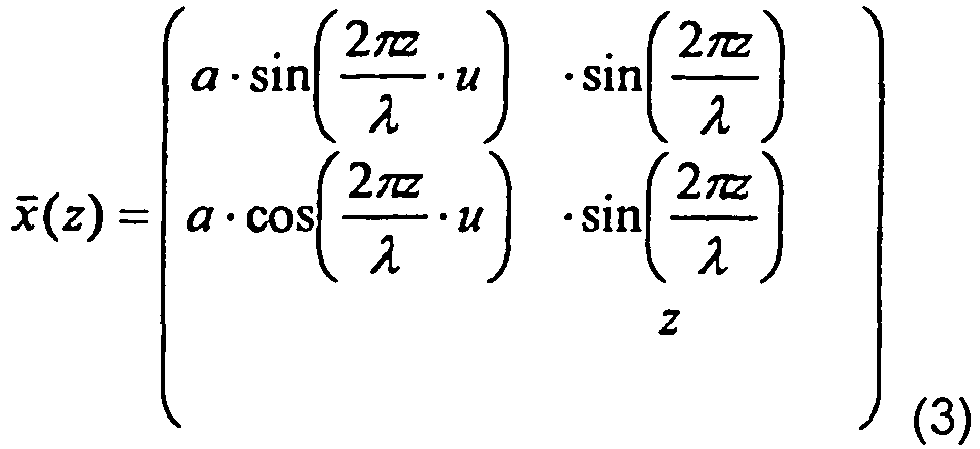
- Gemäß einer besonderen Ausgestaltung der Erfindung kann die Lockung der Hohlfaser eine dreidimensionale Ausrichtung gemäß der folgenden Formeln aufweisen:

-
x - (z)den Raumvektor zwischen dem Koordinatenursprung und der räumlichen Position einer Hohlfaser darstellt, die sich entlang der z-Achse erstreckt, und
- u
- die Anzahl der Umdrehungen pro Wellenlänge λ.
- Entsprechend der vorgenannten Gleichung läuft die Lockung der Hohlfasern zirkular um. Das bedeutet, daß der mathematische Vektor der Amplitude, der von der z-Achse ausgeht und an der Faser endet, innerhalb der Strecke λ einen gewissen Winkelbereich durchläuft. Auf diese Weise entsteht eine dreidimensionale Struktur, die einer Helix ähnlich ist. Während es bei einer zweidimensionalen Struktur durchaus vorkommen kann, daß alle Fasern "umfallen" und so eine anisotrope Struktur bilden, die das Eindringen von Dialysat ins Bündel richtungsabhängig macht, ist ein dreidimensional gelocktes Faserbündel isotrop und gewährleistet ein von allen Seiten gleichmäßiges Eindringen des Dialysats in das Bündelinnere.
- Die Faserbelegung beträgt im zylindrischen Filtergehäuse zwischen 60,5% bis 70%, vorteilhafter 60,5% bis 67,5%. Bei diesen Packungsdichten ist eine dichte Packung mit Dichtung durch Verguß im Endbereich der Hohlfaserbündel möglich.
- Besonders vorteilhaft kann die Faserbelegung im zylindrischen Filtergehäuse zwischen 63,5% bis 65,5% betragen. Die Faserbelegung errechnet sich hierbei aus den Prozenten der durch Fasern belegten Querschnittsfläche pro nutzbarer Querschnittsfläche im Filtergehäuse. Die nutzbare Querschnittsfläche ist das 0,907fache der Querschnittsfläche. Dieser Wert ergibt sich aus der maximalen Packungsdichte (hexagonale Anordnung), die einer Belegung von 100% entsprechen soll. Die oben angegebenen Belegungangaben können insbesondere bei Verwendung der erfindungsgemäßen Abmessung der Hohlfasern erreicht werden und sorgen gleichzeitig dafür, daß die Polyurethanmasse beim Vergießen der Fasern gleichmäßig in das Faserbündel eindringt, ähnlich - wie zuvor beschrieben - , das Dialysat während der Dialyse gleichmäßig ins Bündelinnere gelangt. Gerade durch das gleichmäßige Eindringen der Polyurethanmasse, die anschließend erstarrt und das Faserbündel als solches an beiden Enden fixiert, kann die gleichmäßige Belegung des Faserbündels und somit die zuvorgenannte hohe Packungsdichte erreicht werden.
- Der erfindungsgemäße Effekt wird auch durch eine Kombination aus langgestreckten flachen und dreidimensional gelockten Fasern erzielt, wenn mindestens 10% dreidimensional gelockter Fasern im Faserbündel verwendet werden.
- Die Erfindung bezieht sich auch auf eine gelockte Hohlfaser zum wahlweisen Einsatz in Form eines Bündels in Hohlfaserdialysatoren, die unterschiedliche Durchmesser D von einem minimalen Durchmesser DMin bis zu einem maximalen Durchmesser DMax aufweisen können. In diesem Fall soll möglichst eine optimale Hohlfasergestalt bereitgestellt werden, die für Hohlfaserdialysatoren unterschiedlichster Durchmesser Anwendung finden kann. Die gelockte Hohlfaser für den Einsatz in Filtergehäusen unterschiedlicher Durchmesser ergibt sich dabei aus folgender Gleichung:

- Eine beispielhafte Ausführungsform der Hohlfasern besteht aus 90 bis 99 Gewichtsprozent eines hydrophoben ersten Polymers und 10 bis 1 Gewichtsprozent eines hydrophilen zweiten Polymers, wobei die hydrophoben ersten Polymere aus folgender Gruppe ausgewählt sind: Polyarylsulfone, Polycarbonate, Polyamide, Polyvinylchlorid, modifizierte Acrylsäure, Polyether, Polyurethane oder deren Co-Polymere und wobei die hydrophilen zweiten Polymere aus folgender Gruppe ausgewählt sind: Polyvinylpyrrolidon, Polyethylenglycol, Polyglycolmonoesther, Co-Polymere von Polyethylenglycol mit Polypropylenglycol, wasserlösliche Derivate der Zellulose oder Polysorbate. Diese Zusammensetzung der mikroporösen Hohlfasern ist bereits ausführlich in der
EP 0168783 A1 beschrieben, der auch weitere Details zu diesem Beispiel zu entnehmen sind. - Weitere Beispiele für die Gestaltung der Hohlfasern bezüglich Zusammensetzung und Morphologie finden sich in der
EP 0 305 787 A1 sowie in der AuslegeschriftDE 21 45 183 . Auf die Offenbarung dieser Schriften wird ausdrücklich Bezug genommen. - Ein erfindungsgemäße Hohlfaserdialysator kann mit einem Verfahren befüllt werden, wobei die zu Beginn der Befüllung im Außenraum, d.h. den die Hohlfasern umgebenden Raum, vorhandene Luft durch einen von oben nach unten durch das Filtergehäuse geführten Flüssigkeitsvolumenstrom verdrängt wird. Dabei beträgt der Flüssigkeitsvolumenstrom zur Befüllung des Filtergehäuses vorzugsweise ca. 500 ml/min. Es hat sich überraschend gezeigt, daß durch den erfindungsgemäßen Aufbau des Hohlfaserdialysators, wie er zuvor beschrieben wurde, beide Fluidkammern des Dialysators befüllt werden können, ohne den Dialysator um 180° drehen zu müssen.
- Nach dem Stand der Technik, bei dem das Faserbündel nicht so gleichmäßig und packungsdicht aufgebaut war, wie dies gemäß der vorliegenden Erfindung möglich ist, mußte zur luftfreien Befüllung des Systems, dieses bei vertikaler Filterstellung von unten nach oben befüllt werden. Da die Dialysierflüssigkeitspumpe und die Blutpumpe im allgemeinen entgegensetzt fördern, mußte die Befüllung der jeweiligen Kammer mit Dialysierflüssigkeit nach dem Stand der Technik dialysatseitig bzw. mit isotoner Kochsalzlösung blutseitig hintereinander erfolgen, wobei der Filter vor dem zweiten Schritt um 180° gedreht werden mußte. Mit dem neuen Filter ist diese Verfahrensführung bei der Befüllung nun nicht mehr notwendig. Der Dialysatraum kann von oben nach unten befüllt werden. Dabei kann die Befüllung gleichzeitig mit der blutseitigen Befüllung erfolgen, ohne daß hier der Dialysator gedreht werden müßte.
- Schließlich betrifft die Erfindung die Verwendung der zuvor beschriebenen erfindungsgemäßen Filtervorrichtung zum Befüllen des Filtergehäuses mittels eines von oben nach unten durch das Filtergehäuse geführten Flüssigkeitsvolumenstroms.
- Diese Verwendung der erfindungsgemäßen Filtervorrichtung ermöglicht eine schnelle und vor allem luftfreie Befüllung des Systems. Die höhere Befüllungsgeschwindigkeit ergibt sich daher, daß beide Fluidkammern des Dialysators, d.h. die dialysatseitige und die blutseitige Kammer gleichzeitig befüllt werden können, ohne daß die Filtervorrichtung gedreht werden muß.
- Weitere Einzelheiten der Erfindung werden anhand eines in der Zeichnung dargestellten Ausführungsbeispiels näher erläutert.
- Es zeigen:
- Fig. 1:
- einen Längsschnitt bzw. Querschnitt durch ein Hohlfaserbündel und
- Fig. 2:
- die Geometrie einer einzelnen Hohlfaser gemäß der vorliegenden Erfindung.
- In
Figur 1 ist ein mikrogelocktes Hohlfaserbündel der effektiven Länge L mit dem Durchmesser D dargestellt. Dieses ist in an sich bekannter Art und Weise üblicherweise in einem hier nicht näher dargestellten Filtergehäuse angeordnet. Der Aufbau einer Filtervorrichtung ist an sich umfassend bekannt und wird daher hier nicht im einzelnen beschrieben. Allgemein besteht jedenfalls eine bekannte Filtervorrichtung, wie beispielsweise ein Hohlfaserdialysator, aus einem rohrförmigen Gehäuse, das das Hohlfaserbündel einfaßt, wobei die Enden des Hohlfaserbündels durch eine Vergußmasse mit den Enden des rohrförmigen Gehäuses verbunden sind. Bei dieser Filtervorrichtung ist das Gehäuse jeweils eingrenzend an die Vergußmassen mit radialen Anschlußstutzen versehen, die die Ein- und Ausgänge zu dem zweiten Strömungsraum bilden. Zur Öffnung der von den Vergußmassen eingefaßten Kapillarröhren des Hohlfaserbündels werden diese an ihren Stirnseiten angeschnitten. Auf die Enden des rohrförmigen Mantels werden sodann dichtende Kappen aufgesetzt, die mit Stutzen versehen sind, die die Ein- und Ausgänge des ersten Strömungsraums bilden. - Im übrigen wird beispielhaft auf die Offenbarung der
DE 198 57 850 und derEP-A-0844015 verwiesen. - Gemäß der Erfindung wird eine sinusförmige Texturierung von Hohlfasermembranen erzeugt, wobei die Wellenlänge λ der periodischen Struktur eng verknüpft ist mit dem äußeren Durchmesser d der Hohlfaser (vgl.
Fig. 2 ) sowie mit der effektiven Faserlänge L und dem Bündeldurchmesser D (vgl.Fig. 1 ) des Faserbündels. Dabei bewegt sich das erfindungsgemäß optimale λ in folgendem Bereich:
Fig. 2 ). Dies kann dadurch erklärt werden, daß bei Unterschreitung von 5 d keine Wellenbäuche mehr in der Hohlfaser entstehen, die dem Dialysat den Weg ins Faserinnere ermöglichen. Nach oben hin ist die Wellenlänge λ beschränkt durch die Wirksamkeit bei der Leistungssteigerung. Dabei wurde überraschend gefunden, daß es für "dünne Dialysatoren", d.h. Durchmesser-zu Längenverhältnisse von D/L < 0,14, bei gängigen Faserdurchmessern ausreichend ist, wenn 12 Wellenlängen pro Faserlänge L vorhanden sind. Bei "dickeren Dialysatoren" mit einem ungünstigen Verhältnis von Durchmesser zu Länge, d.h. von D/L, wird es bei gleicher Wellenlänge λ schwieriger für das Dialysat in die Mitte des Faserbündels zu gelangen. Um dies zu kompensieren, wird in der Gleichung die Geometrie bei der Berechnung der maximalen Wellenlänge mit dem Faktor 1/(1+2 D/L) berücksichtigt. - Soll für alle Dialysatorgrößen für eine Hohlfaser die gleiche Wellenlänge λ benutzt werden, so muß in der Gleichung (1) D durch den maximalen Durchmesser DMax ersetzt werden. Hierdurch wird erreicht, daß eine Durchdringung des Faserbündels auch bei ungünstigen Durchmesser- zu Längenverhältnissen gewährleistet ist. Erst rechtwerden dann vergleichsweise schlankere Dialysatoren von dem Dialysat durchströmt.
- Für Dialysefasern mit einem Durchmesser von d=0,28 mm und dem Dialysator mit der größten Dicke, der eine effektive Länge von L=225 mm und einen maximalen Innendurchmesser von DMax=48 mm aufweist, ergibt sich ein Bereich für die Wellenlänge λ von

- In der Praxis haben sich Werte für die Wellenlänge λ von

- Neben der Wellenlänge λ spielt auch die Amplitude eine wichtige Rolle bei der Wirksamkeit der Mikrolockung. Die Amplitude a (vgl.
Fig. 2 ) sollte sich dabei im folgenden Bereich bewegen:
- Wird dagegen a größer als λ/5 gewählt, so wird eine vergleichsweise geringere Packungsdichte in Kauf genommen, die zu einem Absinken der Effektivität des Stoffaustausches führt.
- Mittels der sogenannten Mikrolockung wird es gewährleistet, daß überall entlang der Hohlfasern durch die Wellenbäuche das Dialysat ins Hohlfaserbündelinnere geleitet wird und gleichzeitig die Strömung entlang der Hohlfasern immer wieder abgelenkt und gebremst wird. Hierdurch kann ein optimaler Stoffaustausch entlang der Austauschfläche erfolgen.
- Besondere Vorteile ergeben sich bei Verwendung der mit der vorgenannten Mikrolockung versehenen Hohlfasern in Form eines dichtgepackten Faserbündels, insbesondere entsprechend der zuvor im einzelnen diskutierten Packungsdichte, da eine Filtervorrichtung mit einer derartigen Hohlfaserpackung einfacher befüllt werden kann. Hier können beide Fluidkammern, nämlich die dialysatseitige sowie die blutseitige Kammer, gleichzeitig und insbesondere luftfrei befüllt werden. Hieraus ergibt sich ein entscheidender Vorteil gegenüber dem bisherigen Stand der Technik, bei dem die Kammer für die Dialysierflüssigkeit und die blutseitige Kammer nacheinander befüllt werden mussten, wobei zusätzlich die Filtervorrichtung zum luftfreien Befüllen um 180 Grad gedreht werden musste. Dies bedingte eine kompliziertere Handhabung, die bei Verwendung der erfindungsgemäßen mikrogelockten Hohlfaser in der erfindungsgemäßen Filtervorrichtung nicht mehr notwendig ist.
Claims (5)
- Filtervorrichtung bestehend aus einem zylindrischen Filtergehäuse und einem in diesem angeordneten zylinderförmigen Bündel aus gelockten Hohlfasern, wobei alle Hohlfasern eine periodische, sinusförmige Texturierung aufweisen und entsprechend folgender geometrischer Gesetzmäßigkeit gelockt sind:

und wobei es sich bei der Filtervorrichtung um einen Hohlfaserdialysator für die Hämodialyse handelt, der von derjenigen Bauart ist, dass durch das Innere der Fasern Blut fließt und im Raum zwischen Fasern und Filtergehäuse Dialysat entlang der Fasern in axialer Richtung im Gegenstrom zum Blut fließt, und dass die Faserbelegung im zylindrischen Filtergehäuse 60,5% bis 70% beträgt. - Filtervorrichtung nach Anspruch 1, dadurch gekennzeichnet, dass sich die Amplitude a der Lockung aus folgender Gleichung ergibt:

- Filtervorrichtung nach Anspruch 1 oder 2, dadurch gekennzeichnet, dass die Lockung der Hohlfaser eine dreidimensionale Ausrichtung gemäß der folgenden Formeln aufweist:
x (z) den Raumvektor zwischen dem Koordinatenursprung und der räumlichen Position einer Hohlfaser darstellt, die sich entlang der z-Achse erstreckt, und u die Anzahl der Umdrehungen pro Wellenlänge λ. - Filtervorrichtung nach einem der Ansprüche 1 bis 3, dadurch gekennzeichnet, dass die Faserbelegung im zylindrischen Filtergehäuse zwischen 63,5% bis 65,5% beträgt.
- Filtervorrichtung nach einem der Ansprüche 1 bis 4, dadurch gekennzeichnet, dass zumindest 10% der Hohlfasern dreidimensional gelockte Hohlfasern sind.
Applications Claiming Priority (3)
| Application Number | Priority Date | Filing Date | Title |
|---|---|---|---|
| DE10007327A DE10007327A1 (de) | 2000-02-17 | 2000-02-17 | Filtervorrichtung, vorzugsweise Hohlfaserdialysator mit gelockten Hohlfasern |
| PCT/EP2001/001752 WO2001060477A2 (de) | 2000-02-17 | 2001-02-16 | Filtervorrichtung, vorzugsweise hohlfaserdialysator mit gelockten hohlfasern |
| EP01909766A EP1257333B1 (de) | 2000-02-17 | 2001-02-16 | Verfahren zur befüllung einer filtervorrichtung, vorzugsweise hohlfaserdialysator mit gelockten hohlfasern |
Related Parent Applications (2)
| Application Number | Title | Priority Date | Filing Date |
|---|---|---|---|
| EP01909766A Division EP1257333B1 (de) | 2000-02-17 | 2001-02-16 | Verfahren zur befüllung einer filtervorrichtung, vorzugsweise hohlfaserdialysator mit gelockten hohlfasern |
| EP01909766.6 Division | 2001-02-16 |
Publications (3)
| Publication Number | Publication Date |
|---|---|
| EP1671695A1 EP1671695A1 (de) | 2006-06-21 |
| EP1671695B1 EP1671695B1 (de) | 2014-01-01 |
| EP1671695B2 true EP1671695B2 (de) | 2021-03-17 |
Family
ID=7631359
Family Applications (2)
| Application Number | Title | Priority Date | Filing Date |
|---|---|---|---|
| EP01909766A Expired - Lifetime EP1257333B1 (de) | 2000-02-17 | 2001-02-16 | Verfahren zur befüllung einer filtervorrichtung, vorzugsweise hohlfaserdialysator mit gelockten hohlfasern |
| EP06002619.2A Expired - Lifetime EP1671695B2 (de) | 2000-02-17 | 2001-02-16 | Hohlfaserdialysator mit gelockten Hohlfasern |
Family Applications Before (1)
| Application Number | Title | Priority Date | Filing Date |
|---|---|---|---|
| EP01909766A Expired - Lifetime EP1257333B1 (de) | 2000-02-17 | 2001-02-16 | Verfahren zur befüllung einer filtervorrichtung, vorzugsweise hohlfaserdialysator mit gelockten hohlfasern |
Country Status (15)
| Country | Link |
|---|---|
| US (2) | US20030155294A1 (de) |
| EP (2) | EP1257333B1 (de) |
| JP (1) | JP4584522B2 (de) |
| KR (1) | KR100697677B1 (de) |
| CN (2) | CN100531871C (de) |
| AT (1) | ATE327808T1 (de) |
| AU (1) | AU776506B2 (de) |
| BR (1) | BRPI0108451B1 (de) |
| CA (1) | CA2400773C (de) |
| DE (2) | DE10007327A1 (de) |
| DK (2) | DK1257333T3 (de) |
| ES (2) | ES2261380T3 (de) |
| MX (1) | MXPA02008024A (de) |
| PT (2) | PT1257333E (de) |
| WO (1) | WO2001060477A2 (de) |
Families Citing this family (54)
| Publication number | Priority date | Publication date | Assignee | Title |
|---|---|---|---|---|
| DE10007327A1 (de) | 2000-02-17 | 2001-08-30 | Fresenius Medical Care De Gmbh | Filtervorrichtung, vorzugsweise Hohlfaserdialysator mit gelockten Hohlfasern |
| AU2003209410A1 (en) * | 2002-01-29 | 2003-09-02 | Amersham Biosciences Membrane Separations Corp. | Convoluted surface hollow fiber membranes |
| US8496826B2 (en) | 2003-04-23 | 2013-07-30 | Asahi Kasei Medical Co., Ltd. | Body fluid treating device of hollow fiber membrane type |
| ATE354429T1 (de) * | 2003-11-07 | 2007-03-15 | Gambro Lundia Ab | Endkappenanordnung mit einem schlauch für eine pumpe für ein filter und filter mit einer solchen endkappenanordnung |
| CN101035576B (zh) | 2004-08-06 | 2011-01-12 | 旭化成可乐丽医疗株式会社 | 聚砜血液透析器 |
| JP4599934B2 (ja) * | 2004-08-10 | 2010-12-15 | 東洋紡績株式会社 | 中空糸膜モジュール |
| CA2676161A1 (en) * | 2007-01-30 | 2008-08-07 | Toray Industries, Inc. | Crimped hollow fiber membrane and membrane module comprising same |
| CA2704567C (en) * | 2007-12-27 | 2016-01-12 | Toray Industries, Inc. | Fiber construct for treating biological components |
| EP2156881A1 (de) * | 2008-08-22 | 2010-02-24 | Gambro Lundia AB | Verteilungs- bzw. Filtrierungsvorrichtung |
| ATE531445T1 (de) | 2009-05-20 | 2011-11-15 | Gambro Lundia Ab | Membranen mit verbesserter leistung |
| EP2253369B1 (de) | 2009-05-20 | 2011-11-09 | Gambro Lundia AB | Membranen mit verbesserter Leistung |
| EP2253367B1 (de) | 2009-05-20 | 2014-11-19 | Gambro Lundia AB | Membranen mit verbesserter Leistung |
| EP2253370B1 (de) | 2009-05-20 | 2014-10-01 | Gambro Lundia AB | Hohlfasermembranen mit verbesserter Leistung |
| EP2556849A1 (de) | 2011-08-08 | 2013-02-13 | Gambro Lundia AB | Trennmaterial |
| EP2556848A1 (de) | 2011-08-08 | 2013-02-13 | Gambro Lundia AB | Trennmaterial umfassend Saccharidliganden |
| EP2567750B1 (de) | 2011-09-08 | 2014-12-24 | Gambro Lundia AB | Hohlfasermembran |
| CN202740496U (zh) | 2012-06-21 | 2013-02-20 | 甘布罗伦迪亚股份公司 | 毛细管透析器 |
| EP2735358B1 (de) | 2012-11-22 | 2018-01-10 | Gambro Lundia AB | Hohlfaserdialysatoren |
| EP2735360B1 (de) | 2012-11-26 | 2017-04-12 | Gambro Lundia AB | Adsorptionsvorrichtung umfassend eine Kombinationen aus Hohlfasermembranen und Beads |
| EP2735359B1 (de) | 2012-11-26 | 2017-02-08 | Gambro Lundia AB | Integrierte Vorrichtung für Leberunterstützungssysteme |
| EP2735326B1 (de) | 2012-11-26 | 2017-03-08 | Gambro Lundia AB | Leberunterstützungssytem |
| KR20140099752A (ko) * | 2013-02-04 | 2014-08-13 | 코오롱인더스트리 주식회사 | 중공사막 및 이를 포함하는 중공사막 모듈 |
| US9433720B2 (en) | 2013-03-14 | 2016-09-06 | Fresenius Medical Care Holdings, Inc. | Universal portable artificial kidney for hemodialysis and peritoneal dialysis |
| US20140263062A1 (en) | 2013-03-14 | 2014-09-18 | Fresenius Medical Care Holdings, Inc. | Universal portable machine for online hemodiafiltration using regenerated dialysate |
| EP2815807A1 (de) | 2013-06-20 | 2014-12-24 | Gambro Lundia AB | Hohlfaserdialysatoren |
| EP2845641B1 (de) | 2013-09-05 | 2018-05-09 | Gambro Lundia AB | Permselektive asymmetrische Membranen mit Polyvinylpyrrolidone hohen Molekulargewichtes, sowie deren Herstellung und Verwendung |
| EP2878362B1 (de) | 2013-12-02 | 2018-07-04 | Gambro Lundia AB | Hohlfaserdialysatoren |
| AU2015214949B2 (en) | 2014-02-06 | 2018-11-01 | Gambro Lundia Ab | Membrane for blood purification |
| CA2938222C (en) | 2014-02-06 | 2022-08-30 | Gambro Lundia Ab | Hemodialyzer for blood purification |
| CZ305152B6 (cs) | 2014-02-13 | 2015-05-20 | Zena S. R. O. | Výměník tepla tvořený dutými polymerními vlákny |
| WO2015153370A2 (en) | 2014-03-29 | 2015-10-08 | Labib Mohamed E | Blood processing cartridges and systems, and methods for extracorporeal blood therapies |
| EP2939731B1 (de) | 2014-04-30 | 2018-10-03 | Gambro Lundia AB | UV-bestrahlte Hohlfasermembranen |
| WO2016111320A1 (ja) * | 2015-01-07 | 2016-07-14 | 旭化成メディカル株式会社 | 濾過器、体腔液処理システム及び体腔液処理方法 |
| KR101766011B1 (ko) * | 2015-04-30 | 2017-08-07 | 현대자동차주식회사 | 연료전지용 막가습기 |
| CN104906972A (zh) * | 2015-05-20 | 2015-09-16 | 苏州市贝克生物科技有限公司 | 一种纳米二氧化钛/聚醚血液透析膜及其制备方法 |
| US10426884B2 (en) | 2015-06-26 | 2019-10-01 | Novaflux Inc. | Cartridges and systems for outside-in flow in membrane-based therapies |
| US10399040B2 (en) | 2015-09-24 | 2019-09-03 | Novaflux Inc. | Cartridges and systems for membrane-based therapies |
| DE102016002440A1 (de) * | 2016-03-01 | 2017-09-07 | Fresenius Medical Care Deutschland Gmbh | Hohlfasermembran mit dreidimensionaler Lockung |
| EP3290100B1 (de) | 2016-08-31 | 2020-08-19 | Gambro Lundia AB | Diffusions- und/oder filtrationsvorrichtung |
| EP3290067B1 (de) | 2016-09-06 | 2021-03-03 | Gambro Lundia AB | Leberunterstützungssystem |
| DE102016012730A1 (de) | 2016-10-24 | 2018-04-26 | Fresenius Medical Care Deutschland Gmbh | Verfahren zur Bestimmung einer Permeationseigenschaft von Hohlfasermembranen |
| DE102016012722A1 (de) | 2016-10-24 | 2018-04-26 | Fresenius Medical Care Deutschland Gmbh | Verfahren zur Bestimmung einer Permeationseigenschaft von Hohlfasermembranen |
| DE102017204524A1 (de) * | 2017-03-17 | 2018-09-20 | Fresenius Medical Care Deutschland Gmbh | Hohlfasermembran mit verbesserten Diffusionseigenschaften |
| EP3388139A1 (de) | 2017-04-13 | 2018-10-17 | Gambro Lundia AB | Optimierter hämodialysator für die blutreinigung |
| EP3495033A1 (de) | 2017-12-11 | 2019-06-12 | Gambro Lundia AB | Hohlfaserdialysator |
| EP3669888A1 (de) | 2018-12-20 | 2020-06-24 | Gambro Lundia AB | Extrakorporale vorrichtungen für verfahren zur behandlung von erkrankungen im zusammenhang mit zytoplasmischen anti-neutrophil-antikörpern |
| CN112245691A (zh) | 2019-07-22 | 2021-01-22 | 巴克斯特医疗保健股份有限公司 | 从原水制备透析液的方法和系统 |
| US11013841B2 (en) | 2019-09-28 | 2021-05-25 | Choon Kee Lee | Centrifugal-dialysate-flow hemodializer |
| US11071951B2 (en) | 2019-09-29 | 2021-07-27 | Choon Kee Lee | Centrifugal gradient dialysate dual-chamber hemodiafiltrator |
| JPWO2021100811A1 (de) * | 2019-11-20 | 2021-05-27 | ||
| EP3838384A1 (de) | 2019-12-21 | 2021-06-23 | Gambro Lundia AB | Übergabe von fasebündlen |
| US11040128B1 (en) | 2020-01-25 | 2021-06-22 | Choon Kee Lee | Integrated motorized hemodialyzer |
| CN112915803A (zh) * | 2021-01-12 | 2021-06-08 | 宁波方太厨具有限公司 | 一种微波浪形状中空纤维纳滤膜的制备方法 |
| DE102021112315A1 (de) | 2021-05-11 | 2022-11-17 | Fresenius Medical Care Deutschland Gmbh | Hohlfasermembranfilter mit verbesserten Trenneigenschaften |
Family Cites Families (34)
| Publication number | Priority date | Publication date | Assignee | Title |
|---|---|---|---|---|
| US3616928A (en) | 1969-10-02 | 1971-11-02 | Du Pont | Permeation separation device for separating fluids |
| BE771649A (fr) | 1970-09-09 | 1971-12-31 | Fives Lille Cail | Four ou echangeur de chaleur tubulaire et rotatif comportant aumoins une zone renforcee par une structure annulaire |
| JPS5073882A (de) * | 1973-11-02 | 1975-06-18 | ||
| US4336138A (en) * | 1975-07-26 | 1982-06-22 | Toyobo Co., Ltd. | Permeation separation apparatus |
| IN149938B (de) * | 1977-11-30 | 1982-06-12 | Monsanto Co | |
| DE2842958A1 (de) * | 1978-10-02 | 1980-04-10 | Akzo Gmbh | Dialysehohlfadenmembran mit laengswellen |
| US4293418A (en) * | 1979-03-28 | 1981-10-06 | Toray Industries, Inc. | Fluid separation apparatus |
| US4324662A (en) | 1979-12-28 | 1982-04-13 | Baxter Travenol Laboratories, Inc. | Flow reversal in a dialyzer |
| US4331540A (en) * | 1980-04-21 | 1982-05-25 | Baxter Travenol Laboratories, Inc. | Process for draining dialysate from artificial kidney |
| US4352736A (en) * | 1980-12-08 | 1982-10-05 | Toyo Boseki Kabushiki Kaisha | Wound flattened hollow fiber assembly having plural spaced core sections |
| JPS57194007A (en) * | 1981-05-26 | 1982-11-29 | Nitsushiyoo:Kk | Hollow yarn type permeating device |
| JPS5884007A (ja) * | 1981-11-14 | 1983-05-20 | Toyobo Co Ltd | 透析用中空繊維膜及びその製造法 |
| DE3301268A1 (de) * | 1983-01-17 | 1984-07-26 | Akzo Gmbh, 5600 Wuppertal | Verfahren und vorrichtung zum herstellen von hohlfadenbuendeln |
| US4906375A (en) * | 1984-07-14 | 1990-03-06 | Fresenius, Ag | Asymmetrical microporous hollow fiber for hemodialysis |
| DE3426331A1 (de) * | 1984-07-17 | 1986-01-30 | 6380 Bad Homburg Fresenius AG | Asymmetrische mikroporoese hohlfaser fuer die haemodialyse sowie verfahren zu ihrer herstellung |
| JPS6245709A (ja) | 1985-08-21 | 1987-02-27 | Teijin Ltd | 選択透過性中空糸及び流体分離器 |
| SE460521B (sv) | 1987-08-31 | 1989-10-23 | Gambro Dialysatoren | Permselektiv asymmetriskt membran samt foerfarande foer dess framstaellning |
| EP0314581B1 (de) * | 1987-10-29 | 1994-06-22 | Terumo Kabushiki Kaisha | Oxygenator mit porösen Hohlfasernmembranen |
| JPH067859B2 (ja) * | 1987-10-29 | 1994-02-02 | テルモ株式会社 | 多孔質中空糸膜および中空糸膜型人工肺 |
| JPH01219710A (ja) | 1988-02-26 | 1989-09-01 | Canon Inc | ズームレンズ |
| US5110477A (en) * | 1990-02-13 | 1992-05-05 | Howard David B | Dialyzer clearance check system |
| JPH0553592A (ja) | 1991-08-29 | 1993-03-05 | Pioneer Electron Corp | カラオケシステム |
| JP3001774B2 (ja) * | 1994-06-28 | 2000-01-24 | 帝人株式会社 | 血液用中空糸膜の製造方法 |
| EP0705611A2 (de) | 1994-09-07 | 1996-04-10 | David S. Utterberg | Trennbares Hämodialysesystem |
| JPH08110594A (ja) | 1994-10-13 | 1996-04-30 | Toshiba Corp | 画像形成装置 |
| US5650071A (en) | 1995-06-07 | 1997-07-22 | Cobe Laboratories, Inc. | Technique for priming and recirculating fluid through a dialysis machine to prepare the machine for use |
| JPH09266947A (ja) * | 1996-04-02 | 1997-10-14 | Teijin Ltd | 透析用中空糸膜およびモジュール |
| JPH09273315A (ja) | 1996-04-08 | 1997-10-21 | Japan Drive-It Co Ltd | 補強用鋼板の取付穴の位置決め治具 |
| US5779897A (en) * | 1996-11-08 | 1998-07-14 | Permea, Inc. | Hollow fiber membrane device with inert filaments randomly distributed in the inter-fiber voids |
| US6074559A (en) * | 1996-11-21 | 2000-06-13 | Fresenius Medical Care Deutschland Gmbh | Filter device having a hollow fiber bundle and associated sealing devices |
| JPH1190187A (ja) * | 1997-09-22 | 1999-04-06 | Nok Corp | 中空糸膜モジュール |
| DE19857850C2 (de) | 1998-12-15 | 2003-02-06 | Fresenius Medical Care De Gmbh | Filtervorrichtung |
| US6322703B1 (en) * | 1999-04-20 | 2001-11-27 | Asahi Kasei Kabushiki Kaisha | Method for purifying aqueous suspension |
| DE10007327A1 (de) | 2000-02-17 | 2001-08-30 | Fresenius Medical Care De Gmbh | Filtervorrichtung, vorzugsweise Hohlfaserdialysator mit gelockten Hohlfasern |
-
2000
- 2000-02-17 DE DE10007327A patent/DE10007327A1/de not_active Ceased
-
2001
- 2001-02-16 DE DE50109954T patent/DE50109954D1/de not_active Expired - Lifetime
- 2001-02-16 DK DK01909766T patent/DK1257333T3/da active
- 2001-02-16 MX MXPA02008024A patent/MXPA02008024A/es active IP Right Grant
- 2001-02-16 PT PT01909766T patent/PT1257333E/pt unknown
- 2001-02-16 KR KR1020027010137A patent/KR100697677B1/ko active IP Right Grant
- 2001-02-16 JP JP2001559568A patent/JP4584522B2/ja not_active Expired - Lifetime
- 2001-02-16 BR BRPI0108451A patent/BRPI0108451B1/pt active IP Right Grant
- 2001-02-16 AU AU37393/01A patent/AU776506B2/en not_active Expired
- 2001-02-16 EP EP01909766A patent/EP1257333B1/de not_active Expired - Lifetime
- 2001-02-16 US US10/204,181 patent/US20030155294A1/en not_active Abandoned
- 2001-02-16 CN CNB2005101286492A patent/CN100531871C/zh not_active Expired - Lifetime
- 2001-02-16 EP EP06002619.2A patent/EP1671695B2/de not_active Expired - Lifetime
- 2001-02-16 ES ES01909766T patent/ES2261380T3/es not_active Expired - Lifetime
- 2001-02-16 CN CNB018051685A patent/CN1238096C/zh not_active Expired - Lifetime
- 2001-02-16 AT AT01909766T patent/ATE327808T1/de active
- 2001-02-16 DK DK06002619.2T patent/DK1671695T4/da active
- 2001-02-16 ES ES06002619T patent/ES2447019T5/es not_active Expired - Lifetime
- 2001-02-16 WO PCT/EP2001/001752 patent/WO2001060477A2/de active IP Right Grant
- 2001-02-16 PT PT60026192T patent/PT1671695E/pt unknown
- 2001-02-16 CA CA002400773A patent/CA2400773C/en not_active Expired - Lifetime
-
2010
- 2010-03-16 US US12/725,098 patent/US8202428B2/en not_active Expired - Lifetime
Also Published As
Similar Documents
| Publication | Publication Date | Title |
|---|---|---|
| EP1671695B2 (de) | Hohlfaserdialysator mit gelockten Hohlfasern | |
| EP0285812B1 (de) | Mehrlagiger Hohlfadenwickelkörper | |
| EP0265823B1 (de) | Verfahren zum Herstellen eines Hohlfaser-Stoffaustauschmoduls und nach diesem Verfahren hergestelltes Modul | |
| EP0329980B1 (de) | Kapillardialysator | |
| EP0732141A1 (de) | Hohlfadenbündel sowie Stoff- und/oder Wärmetauscher | |
| DE2542438A1 (de) | Dialysator, insbesondere fuer die haemodialyse und verfahren zu seiner herstellung | |
| DE2539574C3 (de) | Flüssigkeitsbehandlungsvorrichtung | |
| EP3436183B1 (de) | Hohlfasermembranvorrichtung für den stoffaustausch und verfahren zur herstellung | |
| DE3105192A1 (de) | Hohlfasermodul sowie verfahren und vorrichtung zu seiner herstellung | |
| DE2746542A1 (de) | Hohlfaserdurchlaessigkeitsgeraet | |
| DE2842118A1 (de) | Verfahren und vorrichtung zur blutdialyse in einer kuenstlichen niere | |
| DE2322571A1 (de) | Neue semipermeable rohrfoermige elemente | |
| DE10259661A1 (de) | Hohlfaser-Modul | |
| DE8506819U1 (de) | Vorrichtung zur Wärme- und/oder Stoffübertragung mit Hilfe von Hohlfäden | |
| DE4308850A1 (de) | Hohlfadenmatte | |
| DE2514763A1 (de) | Dialysegeraet | |
| EP1595554B1 (de) | Intravenöser Oxygenator | |
| DE19532365C2 (de) | Hohlfaseroxygenator | |
| DE2839937A1 (de) | Hohlfaserdialysator mit dialysatfuehrung | |
| DE2721008A1 (de) | Verfahren und vorrichtung zur herstellung von vorrichtungen mit hohlfasern | |
| DE3016636A1 (de) | Stoffaustauschmodul, insbesondere fuer medizinische anwendungen | |
| EP3706887A1 (de) | Membranbündelaufmachung mit abstandshaltern | |
| EP3423173B1 (de) | Hohlfasermembran mit dreidimensionaler lockung | |
| DE4129400A1 (de) | Verfahren zum herstellen eines hohlfadenwickelkoerpers | |
| DE3009528A1 (de) | Hohlfasern mit uneinheitlichem querschnitt und verfahren zu ihrer herstellung |
Legal Events
| Date | Code | Title | Description |
|---|---|---|---|
| PUAI | Public reference made under article 153(3) epc to a published international application that has entered the european phase |
Free format text: ORIGINAL CODE: 0009012 |
|
| 17P | Request for examination filed |
Effective date: 20060208 |
|
| AC | Divisional application: reference to earlier application |
Ref document number: 1257333 Country of ref document: EP Kind code of ref document: P |
|
| AK | Designated contracting states |
Kind code of ref document: A1 Designated state(s): AT BE CH CY DE DK ES FI FR GB GR IE IT LI LU MC NL PT SE TR |
|
| RIN1 | Information on inventor provided before grant (corrected) |
Inventor name: FRITZSCHE, STEFFEN, DR. Inventor name: HEILMANN, KLAUS |
|
| 17Q | First examination report despatched |
Effective date: 20060814 |
|
| AKX | Designation fees paid |
Designated state(s): AT BE CH CY DE DK ES FI FR GB GR IE IT LI LU MC NL PT SE TR |
|
| TPAC | Observations filed by third parties |
Free format text: ORIGINAL CODE: EPIDOSNTIPA |
|
| GRAP | Despatch of communication of intention to grant a patent |
Free format text: ORIGINAL CODE: EPIDOSNIGR1 |
|
| INTG | Intention to grant announced |
Effective date: 20130708 |
|
| GRAS | Grant fee paid |
Free format text: ORIGINAL CODE: EPIDOSNIGR3 |
|
| GRAA | (expected) grant |
Free format text: ORIGINAL CODE: 0009210 |
|
| STAA | Information on the status of an ep patent application or granted ep patent |
Free format text: STATUS: THE PATENT HAS BEEN GRANTED |
|
| AC | Divisional application: reference to earlier application |
Ref document number: 1257333 Country of ref document: EP Kind code of ref document: P |
|
| AK | Designated contracting states |
Kind code of ref document: B1 Designated state(s): AT BE CH CY DE DK ES FI FR GB GR IE IT LI LU MC NL PT SE TR |
|
| REG | Reference to a national code |
Ref country code: GB Ref legal event code: FG4D Free format text: NOT ENGLISH |
|
| REG | Reference to a national code |
Ref country code: CH Ref legal event code: EP Ref country code: CH Ref legal event code: NV Representative=s name: KELLER AND PARTNER PATENTANWAELTE AG, CH |
|
| REG | Reference to a national code |
Ref country code: IE Ref legal event code: FG4D Free format text: LANGUAGE OF EP DOCUMENT: GERMAN |
|
| REG | Reference to a national code |
Ref country code: PT Ref legal event code: SC4A Free format text: AVAILABILITY OF NATIONAL TRANSLATION Effective date: 20140131 |
|
| REG | Reference to a national code |
Ref country code: AT Ref legal event code: REF Ref document number: 647332 Country of ref document: AT Kind code of ref document: T Effective date: 20140215 |
|
| REG | Reference to a national code |
Ref country code: DE Ref legal event code: R096 Ref document number: 50116374 Country of ref document: DE Effective date: 20140220 |
|
| REG | Reference to a national code |
Ref country code: DK Ref legal event code: T3 Effective date: 20140221 |
|
| REG | Reference to a national code |
Ref country code: ES Ref legal event code: FG2A Ref document number: 2447019 Country of ref document: ES Kind code of ref document: T3 Effective date: 20140311 |
|
| REG | Reference to a national code |
Ref country code: NL Ref legal event code: T3 |
|
| REG | Reference to a national code |
Ref country code: SE Ref legal event code: TRGR |
|
| REG | Reference to a national code |
Ref country code: GR Ref legal event code: EP Ref document number: 20140400630 Country of ref document: GR Effective date: 20140416 |
|
| PG25 | Lapsed in a contracting state [announced via postgrant information from national office to epo] |
Ref country code: CY Free format text: LAPSE BECAUSE OF FAILURE TO SUBMIT A TRANSLATION OF THE DESCRIPTION OR TO PAY THE FEE WITHIN THE PRESCRIBED TIME-LIMIT Effective date: 20140101 |
|
| REG | Reference to a national code |
Ref country code: DE Ref legal event code: R026 Ref document number: 50116374 Country of ref document: DE |
|
| PLBI | Opposition filed |
Free format text: ORIGINAL CODE: 0009260 |
|
| PG25 | Lapsed in a contracting state [announced via postgrant information from national office to epo] |
Ref country code: MC Free format text: LAPSE BECAUSE OF FAILURE TO SUBMIT A TRANSLATION OF THE DESCRIPTION OR TO PAY THE FEE WITHIN THE PRESCRIBED TIME-LIMIT Effective date: 20140101 |
|
| PLAX | Notice of opposition and request to file observation + time limit sent |
Free format text: ORIGINAL CODE: EPIDOSNOBS2 |
|
| 26 | Opposition filed |
Opponent name: B. BRAUN AVITUM AG Effective date: 20141001 |
|
| REG | Reference to a national code |
Ref country code: DE Ref legal event code: R026 Ref document number: 50116374 Country of ref document: DE Effective date: 20141001 |
|
| PLAF | Information modified related to communication of a notice of opposition and request to file observations + time limit |
Free format text: ORIGINAL CODE: EPIDOSCOBS2 |
|
| REG | Reference to a national code |
Ref country code: CH Ref legal event code: PCAR Free format text: NEW ADDRESS: EIGERSTRASSE 2 POSTFACH, 3000 BERN 14 (CH) |
|
| PLBB | Reply of patent proprietor to notice(s) of opposition received |
Free format text: ORIGINAL CODE: EPIDOSNOBS3 |
|
| TPAC | Observations filed by third parties |
Free format text: ORIGINAL CODE: EPIDOSNTIPA |
|
| REG | Reference to a national code |
Ref country code: FR Ref legal event code: PLFP Year of fee payment: 16 |
|
| PLAB | Opposition data, opponent's data or that of the opponent's representative modified |
Free format text: ORIGINAL CODE: 0009299OPPO |
|
| PG25 | Lapsed in a contracting state [announced via postgrant information from national office to epo] |
Ref country code: LU Free format text: LAPSE BECAUSE OF NON-PAYMENT OF DUE FEES Effective date: 20140216 |
|
| R26 | Opposition filed (corrected) |
Opponent name: B. BRAUN AVITUM AG Effective date: 20141001 |
|
| REG | Reference to a national code |
Ref country code: FR Ref legal event code: PLFP Year of fee payment: 17 |
|
| APBM | Appeal reference recorded |
Free format text: ORIGINAL CODE: EPIDOSNREFNO |
|
| APBP | Date of receipt of notice of appeal recorded |
Free format text: ORIGINAL CODE: EPIDOSNNOA2O |
|
| APAH | Appeal reference modified |
Free format text: ORIGINAL CODE: EPIDOSCREFNO |
|
| APBQ | Date of receipt of statement of grounds of appeal recorded |
Free format text: ORIGINAL CODE: EPIDOSNNOA3O |
|
| REG | Reference to a national code |
Ref country code: FR Ref legal event code: PLFP Year of fee payment: 18 |
|
| APAH | Appeal reference modified |
Free format text: ORIGINAL CODE: EPIDOSCREFNO |
|
| PLBI | Opposition filed |
Free format text: ORIGINAL CODE: 0009260 |
|
| 26 | Opposition filed |
Opponent name: NIPRO MEDICAL GERMANY GMBH Effective date: 20190809 |
|
| PGFP | Annual fee paid to national office [announced via postgrant information from national office to epo] |
Ref country code: SE Payment date: 20200127 Year of fee payment: 20 Ref country code: PT Payment date: 20200122 Year of fee payment: 20 Ref country code: DE Payment date: 20200121 Year of fee payment: 20 Ref country code: ES Payment date: 20200302 Year of fee payment: 20 Ref country code: GR Payment date: 20200123 Year of fee payment: 20 Ref country code: IT Payment date: 20200121 Year of fee payment: 20 Ref country code: NL Payment date: 20200127 Year of fee payment: 20 Ref country code: GB Payment date: 20200123 Year of fee payment: 20 Ref country code: IE Payment date: 20200123 Year of fee payment: 20 Ref country code: DK Payment date: 20200127 Year of fee payment: 20 Ref country code: FI Payment date: 20200123 Year of fee payment: 20 Ref country code: AT Payment date: 20200123 Year of fee payment: 20 |
|
| PGFP | Annual fee paid to national office [announced via postgrant information from national office to epo] |
Ref country code: BE Payment date: 20200124 Year of fee payment: 20 Ref country code: CH Payment date: 20200123 Year of fee payment: 20 |
|
| PGFP | Annual fee paid to national office [announced via postgrant information from national office to epo] |
Ref country code: FR Payment date: 20200122 Year of fee payment: 20 Ref country code: TR Payment date: 20200204 Year of fee payment: 20 |
|
| REG | Reference to a national code |
Ref country code: CH Ref legal event code: PFA Owner name: FRESENIUS MEDICAL CARE DEUTSCHLAND GMBH, DE Free format text: FORMER OWNER: FRESENIUS MEDICAL CARE DEUTSCHLAND GMBH, DE |
|
| APBU | Appeal procedure closed |
Free format text: ORIGINAL CODE: EPIDOSNNOA9O |
|
| PUAH | Patent maintained in amended form |
Free format text: ORIGINAL CODE: 0009272 |
|
| STAA | Information on the status of an ep patent application or granted ep patent |
Free format text: STATUS: PATENT MAINTAINED AS AMENDED |
|
| REG | Reference to a national code |
Ref country code: DE Ref legal event code: R071 Ref document number: 50116374 Country of ref document: DE |
|
| REG | Reference to a national code |
Ref country code: NL Ref legal event code: MK Effective date: 20210215 |
|
| REG | Reference to a national code |
Ref country code: DK Ref legal event code: EUP Expiry date: 20210216 |
|
| REG | Reference to a national code |
Ref country code: CH Ref legal event code: AELC Ref country code: CH Ref legal event code: PL |
|
| REG | Reference to a national code |
Ref country code: GB Ref legal event code: PE20 Expiry date: 20210215 |
|
| 27A | Patent maintained in amended form |
Effective date: 20210317 |
|
| AK | Designated contracting states |
Kind code of ref document: B2 Designated state(s): AT BE CH CY DE DK ES FI FR GB GR IE IT LI LU MC NL PT SE TR |
|
| REG | Reference to a national code |
Ref country code: DE Ref legal event code: R102 Ref document number: 50116374 Country of ref document: DE |
|
| REG | Reference to a national code |
Ref country code: FI Ref legal event code: MAE |
|
| REG | Reference to a national code |
Ref country code: SE Ref legal event code: EUG |
|
| REG | Reference to a national code |
Ref country code: IE Ref legal event code: MK9A |
|
| REG | Reference to a national code |
Ref country code: SE Ref legal event code: RPEO |
|
| REG | Reference to a national code |
Ref country code: AT Ref legal event code: MK07 Ref document number: 647332 Country of ref document: AT Kind code of ref document: T Effective date: 20210216 |
|
| REG | Reference to a national code |
Ref country code: BE Ref legal event code: MK Effective date: 20210216 |
|
| PG25 | Lapsed in a contracting state [announced via postgrant information from national office to epo] |
Ref country code: PT Free format text: LAPSE BECAUSE OF EXPIRATION OF PROTECTION Effective date: 20210225 Ref country code: GB Free format text: LAPSE BECAUSE OF EXPIRATION OF PROTECTION Effective date: 20210215 Ref country code: IE Free format text: LAPSE BECAUSE OF EXPIRATION OF PROTECTION Effective date: 20210216 |
|
| REG | Reference to a national code |
Ref country code: DE Ref legal event code: R008 Ref document number: 50116374 Country of ref document: DE Ref country code: DE Ref legal event code: R039 Ref document number: 50116374 Country of ref document: DE |
|
| REG | Reference to a national code |
Ref country code: DK Ref legal event code: T4 Effective date: 20210604 |
|
| REG | Reference to a national code |
Ref country code: ES Ref legal event code: FD2A Effective date: 20211029 |
|
| REG | Reference to a national code |
Ref country code: ES Ref legal event code: DC2A Ref document number: 2447019 Country of ref document: ES Kind code of ref document: T5 Effective date: 20220112 |
|
| P01 | Opt-out of the competence of the unified patent court (upc) registered |
Effective date: 20230602 |