EP1671001B1 - Schloss - Google Patents
Schloss Download PDFInfo
- Publication number
- EP1671001B1 EP1671001B1 EP04763924A EP04763924A EP1671001B1 EP 1671001 B1 EP1671001 B1 EP 1671001B1 EP 04763924 A EP04763924 A EP 04763924A EP 04763924 A EP04763924 A EP 04763924A EP 1671001 B1 EP1671001 B1 EP 1671001B1
- Authority
- EP
- European Patent Office
- Prior art keywords
- lock
- toothed wheel
- shaft
- disposed
- lock cylinder
- Prior art date
- Legal status (The legal status is an assumption and is not a legal conclusion. Google has not performed a legal analysis and makes no representation as to the accuracy of the status listed.)
- Expired - Lifetime
Links
- 230000033001 locomotion Effects 0.000 claims abstract description 43
- 230000008878 coupling Effects 0.000 claims description 3
- 238000010168 coupling process Methods 0.000 claims description 3
- 238000005859 coupling reaction Methods 0.000 claims description 3
- 239000002184 metal Substances 0.000 claims description 3
- 229920002994 synthetic fiber Polymers 0.000 claims 1
- 230000005540 biological transmission Effects 0.000 abstract description 24
- 238000004519 manufacturing process Methods 0.000 description 2
- 210000001520 comb Anatomy 0.000 description 1
- 238000006073 displacement reaction Methods 0.000 description 1
- 230000000694 effects Effects 0.000 description 1
- 239000000463 material Substances 0.000 description 1
Images


Classifications
-
- E—FIXED CONSTRUCTIONS
- E05—LOCKS; KEYS; WINDOW OR DOOR FITTINGS; SAFES
- E05B—LOCKS; ACCESSORIES THEREFOR; HANDCUFFS
- E05B17/00—Accessories in connection with locks
- E05B17/04—Devices for coupling the turning cylinder of a single or a double cylinder lock with the bolt operating member
- E05B17/042—Devices for coupling the turning cylinder of a single or a double cylinder lock with the bolt operating member using toothed wheels or geared sectors
-
- E—FIXED CONSTRUCTIONS
- E05—LOCKS; KEYS; WINDOW OR DOOR FITTINGS; SAFES
- E05B—LOCKS; ACCESSORIES THEREFOR; HANDCUFFS
- E05B53/00—Operation or control of locks by mechanical transmissions, e.g. from a distance
-
- E—FIXED CONSTRUCTIONS
- E05—LOCKS; KEYS; WINDOW OR DOOR FITTINGS; SAFES
- E05B—LOCKS; ACCESSORIES THEREFOR; HANDCUFFS
- E05B63/00—Locks or fastenings with special structural characteristics
- E05B63/0017—Locks with sliding bolt without provision for latching
Definitions
- the invention relates to a lock with a lock cylinder which can be actuated with a key and has a driving tongue, with a push movement exporting element and with a transmission device for transmitting the movement of the driving tongue on the element to this by means of first and second means in the closed position or to move the open position, wherein the transmission means comprises a first gear rotatably disposed about the lock cylinder and rotatable with the driver tongue.
- Such locks are eg from the document EP 7395 A1 known. They are used, inter alia, to lock window or door leaf with the frame. However, these locks or the transmission devices of these locks on a variety of gears. In most cases, there are up to seven gears, which are necessary for the movement of the bolt and are used. In addition, this lock often has too large backset. Although it is quite possible that the first gear is a fully closed gear. However, the assembly is relatively expensive.
- the invention is therefore an object of the invention to provide a lock of the type mentioned, which ensures technically simple means always safe operation and at the same time has small dimensions and is inexpensive to produce.
- the essence of the invention is that, in the simplest embodiment, only three elements can be used to transmit the motion of the driver tongue to the element.
- the rotational movement induced by the driver tongue is transmitted to the first gear, which meshes with the at least second gear. Due to the movement of the first gear and the second gear and thus the shaft is set in rotation, which in turn leads to a movement of the device. Since the at least one shaft is arranged transversely to the lock cylinder axis, very small backset dimensions can also be realized for the first time.
- this second gear has a position such that a re-immerse or come into meshing engagement at least made difficult, since the corresponding teeth of the first and second gears are no longer in the designated position.
- the shaft is provided with a third gear or spindle device which has a greater distance from the second gear than the recess in the region of the free end of the driving tongue and also with the first gear combs. Since the distance between the second and third gear is greater than the recess in the region of the outer edge, meshes always one of the second and third gears with the first gear.
- the device for converting the rotational movement of the first shaft into a pushing movement of the element.
- An advantageous embodiment is given by the fact that the device has a spindle arranged on the shaft, which is in engagement with a transmission member of the element. Due to the rotation of the spindle, the transmission member, which is connected to the element, forcibly guided and also forcibly moved, so that results in a linear movement of the element.
- the transmission member insertable in an opening of the thrust movements element insertable or one of the element or latch projecting and integrally formed with this nose is.
- this nose can be arranged on almost all areas of the bolt.
- a particularly compact design results, however, when the nose is arranged at the inner end of the element or bolt.
- the device has an outer thread arranged on the shaft, which is in engagement with a threaded element arranged on the element.
- the threaded element consists of externally on the element angeodneten grooves or of an internal thread arranged in the element.
- the device consists of a shaft arranged on the thread, which is able to engage in corresponding, arranged on the element recesses.
- the device has a disk arranged on the shaft, which engages with a second spindle arranged on the element.
- the spindle is arranged on the thrust movement exporting element, and this spindle is rotated by the disc in rotation.
- the first wave is arranged virtually next to the lock cylinder.
- a second shaft is present, which is arranged transversely to both the first shaft and the lock cylinder axis and has at least the further fourth gear, that meshes with the second gear. This second shaft can then be arranged above the lock cylinder such that the second shaft then extends above the lock cylinder.
- the element is an approach, a coupling piece of a push rod or a bolt.
- the teeth of the gears There are many ways to shape the teeth of the gears. But it is advantageous if the first gear has a helical toothing and the second or third gear is formed in a helical shape.
- the shaft can be arranged in almost all areas around the lock cylinder with any but suitable orientations.
- a particularly simple arrangement but is given when the shaft is approximately perpendicular to the axis of the lock cylinder.
- the device In order to be able to induce two opposing linear movements either selectively or simultaneously with one transmission device, it is advantageous if the device is designed to transmit two counter-rotating linear movements. But this can be done e.g. be made possible by the fact that the spindle has two opposite slopes. But it is also possible that the external thread has two opposing slopes. At these components with the opposite slopes then two elements can be articulated to perform the thrust movement and thus moved.
- a further device is arranged on the shaft. This can be done simultaneously two pushing movements transmitting elements or bars are set in a linear movement.
- lock cylinder is a commercially available cylinder.
- other lock cylinders can be used as long as they have the corresponding Mit videzunge.
- the lock is made of metal or plastic or a combination thereof.
- the lock 10, 10 I , 10 II , 10 III , 10 IV and 10 V includes a lock cylinder 12 which is operable with a key.
- a Mit Economicszunge 14 is moved on a circular path to effect with a transmission device 18 is a linear movement of a thrusting motion transmitting element 16 in its closed position or its open position.
- this push-motion transmitting element is a bolt 16.
- this element 16 may also be the approach or coupling piece of a push rod or a similar movement-transmitting element.
- the transmission device 18 consists in all embodiments of a rotatable about the lock cylinder 12 and rotatable with the Mit supportivezunge 14 first gear 20.
- This first gear 20 meshes with at least one second gear 22 which is disposed on a shaft 24.
- the shaft 24 is provided with means 26, 28; 34, 36; 38, 40; 42, 44; 46, 48 provided, which puts the latch 16 in a linear or pushing movement.
- the device consists of a shaft 24 arranged on the spindle 26, in which a transmission member 28 of the bolt 16 engages.
- the spindle 26 may have two mutually opposite slopes. This is on the one hand advantageous if the linear movement or the exit of the element or bolt 16 should be designed freely selectable. On the other hand, it is also possible to move simultaneously two elements or bars 16 opposite each other linear.
- the transmission member is a projection 28 projecting from the latch 28, which is arranged at the inner end of the bolt 16.
- the nose 28 is formed integrally with the latch 16.
- the first gear 20 has a recess 30 in which the Mit Sprintunge 14 is received.
- the recess 30 has such a dimension on, the lock cylinder 12 can be pushed through this recess 30 during its assembly.
- the lock cylinder is a commercial profile cylinder 12
- the recess 30 has approximately the shape of the outer contour of the profile cylinder 12.
- all commercial cylinders and even special forms thereof can be used.
- FIGS. 1 to 4 . 6 and 8th A simpler solution is in the FIGS. 1 to 4 . 6 and 8th shown.
- This consists of a third gear 32 or according to FIG. 8 from a spindle device 32 ', which is arranged on the shaft 24 to the second gear 22 with a distance which is greater than the recess 30 in the region of the free Mit Sprintunge 14.
- the third gear 32 is arranged so that it the first gear 20 meshes. Since this distance between the second and third gears 22 and 32 or between the second gear 32 and the spindle device 32 'is greater than this clear width of the recess 30, there is at least one of the two gears 22 or 32 and the second gear 22 or the spindle device 32 'in mesh with the first gear 20.
- first to third gears 20,22 and 32 may have any suitable shapes.
- a helical toothing was selected for the first gear 20.
- the second and third gears 22 and 32 each have a bevel gear shape, with the second and third gears 22 and 32 being disposed on the shaft 24 so that their respective smaller end surfaces are aligned with each other.
- the arrangement of the shaft 24 with respect to the lock cylinder can of course be arranged depending on the desired location of engagement of the bolt 16 with the frame.
- the shaft 24 is arranged approximately perpendicular to the axis of the lock cylinder 12, approximately parallel to the vertical axis of the lock cylinder 12th
- the bolt 16 is moved in the embodiment shown in the direction of the vertical axis of the lock cylinder 12 in the desired position.
- the nose 28 is in engagement with the spindle groove of the spindle 26 and is forcibly guided with the movement of the spindle 26 in the embodiment shown depending on the direction of rotation of the shaft 24 upwards or downwards. Since the nose 28 is in this case made in one piece with the latch 16, therefore, the bolt 16 also performs a linear movement upwards or downwards.
- FIGS. 4 to 7 illustrated second to fourth embodiments will now be described essentially with respect to their differences from the first embodiment.
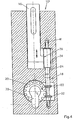
- the Figure 4 shows a lock 10 I , in which the means for implementing the rotational movement of the first shaft 24 in a pushing movement of the element 16 from an arranged on the shaft 24 external thread 34 which is in engagement with a member 16 arranged on the threaded element 36.
- this threaded element 36 consists of grooves 38 which mesh with the external thread 34.
- the remaining parts of this castle 10 I are identical to those of the first embodiment, so that a detailed re-description is omitted.
- the first gear 20 is set in rotation, the shaft 24 and thus also the external thread 34 rotates. Due to this rotation of the external thread 34, the grooves 38 engaged with the external thread 34 become depending on the direction of rotation of the shaft 24 forcibly guided upward or downward according to the drawing.
- This in Figure 5 illustrated third embodiment differs not only in the nature of the device, but also with respect to the transmission device 18.
- This third embodiment has a second shaft 50 which is arranged transversely to both the first shaft 24 and the lock cylinder axis S.
- This second shaft 50 has at least one fourth gear 52, which meshes with the second and third gear 22 and 32, respectively.
- the second shaft 50, a fifth gear 54, which also meshes with the first gear 20 and the fourth gear 52 has a greater distance than the inside diameter of the recess 30 is.
- the third embodiment according to Figure 5 an external thread 34.
- the element 16 is provided with an inner thread 40 arranged in a bore into which the external thread 34 engages.
- the generation of the linear or pushing movement of the element 16 follows in a similar manner as in the second embodiment.
- the fourth embodiment is in Figure 6 shown.
- This fourth embodiment has certain similarities with respect to the means for implementing the rotational movement of the shaft 24 in the linear or pushing movement of the element 16.
- the peculiarity here is that in the shaft 24 only a single thread 42 is formed, which is able to engage in corresponding arranged on the element 16 recesses 44.
- the device consists of a shaft 24 arranged on the disc 46, which is in engagement with a member 16 arranged on the second spindle 48. Due to the high frictional force between the disk 46 and the second spindle 48 to be ensured in this embodiment, rotating the disk 46 also rotates the second spindle 48, forcing it into linear motion.
- the extending portion of the element 16 can be made in one piece with the second spindle 48 or as an extra part.
- FIG. 8 a sixth embodiment of a lock 10 V is shown, which differs from the first embodiment only in that instead of the third gear 32, the spindle device 32 'is present. For the rest, reference is made to the description of the first embodiment.
- the material for the lock 10 metal or plastic or a combination thereof can be selected.
Landscapes
- Lock And Its Accessories (AREA)
- Pharmaceuticals Containing Other Organic And Inorganic Compounds (AREA)
- Hydrogenated Pyridines (AREA)
Description
- Die Erfindung betrifft ein Schloß mit einem Schließzylinder, der mit einem Schlüssel betätigbar ist und eine Mitnehmerzunge aufweist, mit einem Schubbewegung ausführenden Element und mit einer Übertragungseinrichtung zur Übertragung der Bewegung der Mitnehmerzunge auf das Element, um dieses mittels erster und zweiter Einrichtungen in die Schließposition bzw. die Offenposition zu versetzen, wobei die Übertragungseinrichtung ein um den Schließzylinder drehbar angeordnetes und mit der Mitnehmerzunge drehbares erstes Zahnrad aufweist.
- Derartige Schlösser sind z.B. aus dem Dokument
EP 7395 A1 - Dadurch ist dieses Schloß recht kostspielig in der Herstellung, aber auch aufgrund der Komplexität störanfällig.
- Der Erfindung liegt daher die Aufgabe zugrunde ein Schloß der eingangs genannten Art anzugeben, das mit technisch einfachen Mitteln ein stets sicheren Betrieb gewährleistet und gleichzeitig kleine Maße aufweist und kostengünstig herstellbar ist.
- Diese Aufgabe wird bei einem Schloß der eingangs genannten Art erfindungsgemäß durch die Merkmale des kennzeichnenden Teils des Anspruchs 1 gelöst.
- Der Kern der Erfindung besteht darin, daß, in der einfachsten Ausführungsform, zur Übertragung der Bewegung der Mitnehmerzunge auf das Element lediglich drei Elemente verwandt werden können. Dabei wird die von der Mitnehmerzunge induzierte Drehbewegung auf das erste Zahnrad übertragen, das mit dem mindestens zweiten Zahnrad kämmt. Aufgrund der Bewegung des ersten Zahnrades wird auch das zweite Zahnrad und damit auch die Welle in Rotation versetzt, was wiederum auch zu einer Bewegung der Einrichtung führt. Da die mindestens eine Welle quer zur Schließzylinderachse angeordnet ist, können zudem sehr geringe Dornmaße erstmals verwirklicht werden.
- Dabei kann es aber vorkommen, daß nach dem Heraustreten aus dem Kämmeingriff des ersten Zahnrades mit dem zweiten Zahnrad dieses zweite Zahnrad eine derartige Position innehat, daß ein wiedereintauchen bzw. in Kämmeingriff treten zumindest erschwert wird, da die entsprechenden Zähne der ersten und zweiten Zahnräder sich nicht mehr in der dafür vorgesehenen Position befinden.
- Dies kann einerseits dadurch umgangen werden, daß die nach außen weisende Oberfläche der Mitnehmerzunge mit einer zum ersten Zahnrad passenden Verzahnung versehen ist. Dazu ist es allerdings notwendig, diese Oberfläche der Mitnehmerzunge noch einer zusätzlichen Bearbeitung zum Herausarbeiten der Zähne zu unterziehen.
- Falls dies nicht erwünscht ist, ist es vorteilhaft, wenn die Welle mit einem dritten Zahnrad oder Spindeleinrichtung versehen ist, das bzw. die zum zweiten Zahnrad einen größeren Abstand aufweist, als die Aussparung im Bereich des freien Endes der Mitnehmerzunge und ebenfalls mit dem ersten Zahnrad kämmt. Da der Abstand zwischen dem zweiten und dritten Zahnrad größer als die Aussparung im Bereich des Außenrandes ist, kämmt immer eines der zweiten und dritten Zahnräder mit dem ersten Zahnrad.
- Es gibt viele Möglichkeiten für die Ausgestaltung der Einrichtung zur Umsetzung der Rotationsbewegung der ersten Welle in eine Schubbewegung des Elements. Eine vorteilhafte Ausgestaltung ist dadurch gegeben, daß die Einrichtung eine auf der Welle angeordnete Spindel aufweist, die mit einem Übertragungsglied des Elements in Eingriff steht. Aufgrund der Rotation der Spindel wird das Übertragungsglied, das mit dem Element verbunden ist, zwangsgeführt und auch zwangsbewegt, so daß daraus eine Linearbewegung des Elements resultiert.
- Obwohl es mehrere Möglickeiten der Ausgestaltung des Übertragungsgliedes gibt, ist es gemäß einer Weiterbildung der Erfindung vorteilhaft vorgesehen, daß das Übertragungsglied ein in eine Öffnung des Schubbewegungen übertragenden Elements einsteckbares Einsteckteil oder eine von dem Element bzw. Riegel vorspringende und mit diesem einstückig ausgebildete Nase ist.
- Selbstverständlich kann diese Nase an fast allen Bereichen des Riegels angeordnet werden. Eine besonders kompakte Bauweise ergibt sich aber, wenn die Nase an dem inneren Ende des Elements bzw. Riegels angeordnet ist.
- Gemäß einer Weiterbildung der Erfindung ist es vorgesehen, daß die Einrichtung ein auf der Welle angeordnetes Außengewinde aufweist, das mit einem am Element angeordneten Gewindeelement in Eingriff steht.
- Dabei ist es möglich, daß das Gewindeelement aus außen am Element angeodneten Rillen oder aus einem im Element angeordneten Innengewinde besteht.
- Eine besondere Ausführungsform ist dabei dadurch gegeben, daß die Einrichtung aus einem an der Welle angeordneten Gewindegang besteht, der in entsprechenden, am Element angeordneten Aussparungen einzugreifen vermag.
- Ferner ist es vorteilhaft, wenn die Einrichtung eine auf der Welle angeordnete Scheibe aufweist, die mit einer am Element angeordneten zweiten Spindel in Eingriff steht.
- Im Gegensatz zu oben dargestellten Ausführungsbeispiel ist hier die Spindel an dem eine Schubbewegung ausführenden Element angeordnet, und diese Spindel wird von der Scheibe in Rotation versetzt.
- Bei allen bisher beschriebenen Ausführungsformen ist die erste Welle quasi neben dem Schließzylinder angeordnet. Um aber noch geringere Dornmaße zu Verfügung stellen zu können, ist es vorteilhaft, wenn eine zweite Welle vorhanden ist, die sowohl zur ersten Welle als auch zur Schließzylinderachse quer angeordnet ist und mindesten das weitere vierte Zahnrad aufweist, das mit dem zweiten Zahnrad kämmt. Diese zweite Welle kann dann oberhalb des Schließzylinders derart angeordnet werden, daß sich die zweite Welle dann oberhalb des Schließzylinders erstreckt.
- Selbstverständlich können die Ausrichtungen der einzelnen Teile auch anders gewählt werden.
- Gemäß einer Weiterbildung der Erfindung ist es vorgesehen, daß das Element ein Ansatz, ein Kuppelungsstück einer Schubstange oder ein Riegel ist.
- Es gibt viele Möglichkeiten, die Verzahnung der Zahnräder zu gestalten. Vorteilhaft ist es aber, wenn das erste Zahnrad eine Schrägverzahnung aufweist und das zweite bzw. dritte Zahnrad kegelradförmig ausgebildet ist.
- Selbstverständlich kann die Welle in fast allen Bereichen um den Schließzylinder mit beliebigen aber geeigneten Ausrichtungen angeordnet werden. Eine besonders einfache Anordnung ist aber dann gegeben, wenn die Welle in etwa senkrecht zur Achse des Schließzylinders verläuft.
- Um mit einer Übertragungseinrichtung zwei entgegengesetzte Linearbewegungen entweder wahlweise oder gleichzeitig induzieren zu können, ist es vorteilhaft, wenn die Einrichtung zur Übertragung von zwei gegenläufigen Linearbewegungen ausgelegt ist. Dies kann aber z.B. dadurch ermöglicht werden, daß die Spindel zwei gegenläufige Steigungen aufweist. Es ist aber auch möglich, daß das Außengewinde zwei gegenläufige Steigungen aufweist. An diese Bauteile mit den gegenläufigen Steigungen können dann zwei Elemente zur Ausführung der Schubbewegung angelenkt und somit bewegt werden.
- Es ist aber auch möglich, daß eine weitere Einrichtung auf der Welle angeordnet ist. Dadurch können gleichzeitig zwei Schubbewegungen übertragende Elemente bzw. Riegel in eine lineare Bewegung versetzt werden.
- Damit ein Versatz der Linearbewegungen möglich ist, ist es vorteilhaft, wenn mindestens eine weitere Übertragungseinrichtung vorhanden ist. Dabei ist es möglich, zwei Elemente in die gleiche Richtung heraus- bzw. hereinzufahren. Dies kann aber auch in einander entgegengesetzten Richtungen geschehen, wenn die Einrichtung der zweiten Übertragungseinrichtung eine entsprechende Steigung aufweist.
- Weiterhin ist es vorteilhaft, wenn der Schließzylinder ein handelsüblicher Zylinder ist. Selbstverständlich können auch andere Schließzylinder verwandt werden, solange sie die entsprechende Mitnehmerzunge aufweisen.
- Je nach Anwendungsfall ist es vorteilhaft, wenn das Schloß aus Metall oder Kunststoff oder aus einer Kombination daraus besteht.
- Weitere Vorteile und Merkmale der Erfindung ergeben sich aus der folgenden Beschreibung mehrerer Ausführungsbeispiele sowie aus den Zeichnungen, auf die Bezug genommen wird. Es zeigen:
- Fig.1
- eine teilweise geschnittene Seitenansicht eines Schlosses gemäß eines ersten Ausführungsbeispiels;
- Fig.2
- eine teilweise geschnittene Seitenansicht des Schlosses gemäß
Fig.1 gesehen entlang des Pfeiles A vonFig.1 ; - Fig.3
- eine der
Fig.1 ähnliche teilweise geschnittene Seitenansicht ohne Schließzylinder; - Fig.4
- eine Seitenansicht eines Schlosses gemäß eines zweiten Ausführungsbeispiels;
- Fig.5
- eine Seitenansicht eines Schlosses gemäß eines dritten Ausführungsbeispiels;
- Fig.6
- eine Seitenansicht eines Schlosses gemäß eines vierten Ausführungsbeispiels;
- Fig.7
- eine Seitenansicht eines Schlosses gemäß eines fünften Ausführungsbeispiels; und
- Fig.8
- eine Seitenansicht eines Schlosses gemäß eines sechsten Ausführungsbeispiels.
- Anhand der
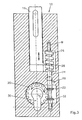
Fig.1 bis 8 werden nunmehr mehrere Ausführungsbeispiele eines Schlosses 10, 10I, 10II, 10III und 10IV näher beschrieben. Dabei bezeichnen gleiche Bezugsziffern die gleichen Elemente, sofern nichts anderes gesagt wird. - Das Schloß 10, 10I, 10II, 10III, 10IV und 10V enthält einen Schließzylinder 12, der mit einem Schlüssel betätigbar ist. Durch die Betätigung des Schlüssels wird eine Mitnehmerzunge 14 auf einer Kreisbahn bewegt, um mit einer Übertragungseinrichtung 18 eine Linearbewegung eines Schubbewegungen übertragenden Elementes 16 in seine Schließposition bzw. seine Offenposition zu bewirken. Bei den beschriebenen Ausführungsbeispielen ist dieses eine Schubbewegung übertragende Element ein Riegel 16. Dieses Element 16 kann aber auch der Ansatz bzw. Kupplungsstück einer Schubstange oder eines ähnlichen bewegungsübertragenden Elementes sein.
- Die Übertragungseinrichtung 18 besteht bei allen Ausführungsbeispielen aus einem um den Schließzylinder 12 drehbar angeordnetes und mit der Mitnehmerzunge 14 drehbares erstes Zahnrad 20. Dieses erste Zahnrad 20 kämmt mit mindestens einem zweiten Zahnrad 22, das auf einer Welle 24 angeordnet ist. Bei dem zum zweiten Zahnrad 22 entgegengesetzten Ende ist die Welle 24 mit einer Einrichtung 26, 28; 34, 36; 38, 40; 42, 44; 46 ,48 versehen, die den Riegel 16 in eine Linear- oder Schubbewegung versetzt.
- Wie in den
Fig.1 bis 3 zu sehen, besteht bei dem ersten Ausführungsbeispiel die Einrichtung aus einer an der Welle 24 angeordneten Spindel 26, in die ein Übertragungsglied 28 des Riegels 16 eingreift. - Obwohl in den
Fig.1 bis 3 nicht dargestellt, kann die Spindel 26 zwei einander gegenläufige Steigungen aufweisen. Dies ist einerseits von Vorteil, wenn die Linearbewegung bzw. der Austritt des Elementes bzw. Riegels 16 frei wählbar gestaltet werden soll. Andererseits ist es aber damit auch möglich, gleichzeitig zwei Elemente bzw. Riegel 16 einander entgegengesetzt linear zu bewegen. - Diese einander entgegengesetzten Linearbewegungen können aber auch dadurch sichergestellt werden, daß eine weitere Spindel 26 auf der Welle 24 angeordnet ist. Dies ist aber ebenfalls in den
Figuren 1 bis 3 nicht dargestellt. - Um die Positionen des Ausfahren des Elementes bzw. des Riegels 16 noch weiter variieren zu können, kann es vorgesehen werden, mindestens eine weitere Übertragungseinrichtung 18 anzuordnen. Selbstverständlich ist die Ausrichtung der einzelnen Übertragungseinrichtungen 18 frei wählbar. Dies gilt wiederum für alle Ausführungsbeispiele.
- Bei dem ersten Ausführungsbeispiel ist das Übertragungsglied eine von dem Riegel 16 vorspringende Nase 28, die an dem inneren Ende des Riegels 16 angeordnet ist. In diesem Fall ist also die Nase 28 einstückig mit dem Riegel 16 ausgebildet. Es ist aber auch möglich, was nicht dargestellt ist, das Übertragungsglied 28 als separates Teil auszubilden, das dann in eine entsprechende Öffnung des Elements bzw. Riegels 16 eingesteckt werden kann.
- Das erste Zahnrad 20 weist eine Aussparung 30 auf, in der die Mitnehmerzunge 14 aufgenommen ist. Darüber hinaus weist die Aussparung 30 eine derartige Abmessung auf, das der Schließzylinder 12 bei seiner Montage durch diese Aussparung 30 hindurchsteckbar ist.
- Falls, wie dargestellt, der Schließzylinder ein handelsüblicher Profilzylinder 12 ist, weist die Aussparung 30 in etwa die Form der Außenkontur des Profilzylinders 12 auf. Es können aber alle handelsüblichen Zylinder und sogar Sonderformen davon verwandt werden.
- Es ist zwar möglich, was allerdings nicht dargestellt ist, die nach außen weisende Oberfläche der Mitnehmerzunge 14 mit einer zum ersten Zahnrad 20 passenden Verzahnung zu versehen. Dies dient dazu, stets ein Kämmen des zweiten Zahnrads 22 mit dem ersten Zahnrad 20 bzw. der entsprechenden Verzahnung der Mitnehmerzunge 14 trotz des Vorhandenseins der Aussparung 30 sicherzustellen. Dazu muß allerdings die Mitnehmerzunge 14 einer weiteren Bearbeitung unterzogen werden.
- Eine einfachere Lösung ist in den
Figuren 1 bis 4 ,6 und8 dargestellt. Diese besteht aus einem dritten Zahnrad 32 oder gemäßFigur 8 aus einer Spindeleinrichtung 32', das bzw. die auf der Welle 24 zum zweiten Zahnrad 22 mit einem Abstand angeordnet ist, der größer ist als die Aussparung 30 im Bereich der freien Mitnehmerzunge 14. Selbstverständlich ist das dritte Zahnrad 32 so angeordnet, daß es mit dem ersten Zahnrad 20 kämmt. Da dieser Abstand zwischen dem zweiten und dritten Zahnrädern 22 und 32 bzw. zwischen dem zweiten Zahnrad 32 und der Spindeleinrichtung 32' größer als diese lichte Weite der Aussparung 30 ist, befindet sich zumindest immer eines der beiden Zahnräder 22 oder 32 bzw. das zweite Zahnrad 22 oder die Spindeleinrichtung 32' im Kämmeingriff mit dem ersten Zahnrad 20. - Selbstverständlich können die ersten bis dritten Zahnräder 20,22 und 32 beliebig geeignete Formen aufweisen. Bei den dargestellten Ausführungsbeispielen des Schlosses 10 wurde für das erste Zahnrad 20 eine Schrägverzahnung gewählt. Die zweiten und dritten Zahnräder 22 und 32 weisen jeweils eine Kegelradform auf, wobei die zweiten und dritten Zahnräder 22 und 32 dabei so auf der Welle 24 angeordnet sind, daß ihre jeweiligen kleineren Stirnflächen aufeinander zu ausgerichtet sind.
- Die Anordnung der Welle 24 in Bezug auf den Schließzylinder kann selbstverständlich in Abhängigkeit von dem gewünschten Eingriffsort des Riegels 16 mit dem Blendrahmen angeordnet werden. Bei dem ersten Ausführungsbeispiel ist die Welle 24 in etwa senkrecht zur Achse des Schließzylinders 12 angeordnet, und zwar in etwa parallel zur Hochachse des Schließzylinders 12.
- Dadurch wird der Riegel 16 bei dem gezeigten Ausführungsbeispiel in Richtung der Hochachse des Schließzylinders 12 in die gewünschte Position verfahren.
- Wird mit Hilfe eines nicht dargestellten Schlüssels der Schließzylinder bzw. Profilzylinder 12 betätigt und der Schlüssel gedreht, kommt die Mitnehmerzunge 14 in Eingriff mit dem ersten Zahnrad 20 im Bereich der Aussparung 30. Dadurch wird das erste Zahnrad 20 gedreht, und die Drehbewegung des ersten Zahnrads 20 wird auf die mit diesem kämmenden zweiten und dritten Zahnräder 22 und 32 übertragen. Da die zweiten und dritten Zahnräder 22 und 32 selbstverständlich drehfest mit der Welle 24 verbunden sind, wird auch durch die Rotation der zweiten und dritten Zahnräder 22 und 32 auch die Spindel 26 in Rotation versetzt, die ebenfalls drehfest mit der Welle 24 verbunden ist. Dabei befindet sich die Nase 28 im Eingriff mit der Spindelnut der Spindel 26 und wird mit der Bewegung der Spindel 26 bei dem gezeigten Ausführungsbeispiel je nach Drehsinn der Welle 24 nach oben oder nach unten zwangsgeführt. Da die Nase 28 in diesem Fall einstückig mit dem Riegel 16 ausgeführt ist, führt daher der Riegel 16 ebenfalls eine Linearbewegung nach oben oder nach unten auf.
- Die in den
Figuren 4 bis 7 dargestellten zweiten bis vierten Ausführungsbeispielen werden nunmehr im wesentlichen bezüglich ihrer Unterschiede zu dem ersten Ausführungsbeispiel beschrieben. - Die
Fig.4 zeigt ein Schloß 10I, bei der die Einrichtung zur Umsetzung der Rotationsbewegung der ersten Welle 24 in eine Schubbewegung des Elements 16 aus einem auf der Welle 24 angeordneten Außengewinde 34 besteht, das mit einem am Element 16 angeordneten Gewindeelement 36 in Eingriff steht. GemäßFig.4 besteht dieses Gewindeelement 36 aus Rillen 38, die mit dem Außengewinde 34 kämmen. Die übrigen Teile dieses Schlosses 10I sind mit denjenigen des ersten Ausführungsbeispiels identisch, so daß auf eine detaillierte erneute Beschreibung verzichtet wird. - Wird nun bei dem zweiten Ausführungsbeispiel das erste Zahnrad 20 in Rotation versetzt, dreht sich auch die Welle 24 und somit auch das Außengewinde 34. Aufgrund dieser Rotation des Außengewindes 34 werden die mit dem Außengewinde 34 sich im Eingriff befindlichen Rillen 38 je nach Drehsinn der Welle 24 gemäß der Zeichnung nach oben bzw. nach unten zwangsgeführt.
- Das in
Fig.5 dargestellte dritte Ausführungsbeispiel unterscheidet sich nicht nur in der Art der Einrichtung, sondern auch noch bezüglich der Übertragungseinrichtung 18. Dieses dritte Ausführungsbeispiel weist eine zweite Welle 50, die sowohl zur ersten Welle 24 als auch zur Schließzylinderachse S quer angeordnet ist. Diese zweite Welle 50 weist mindestens ein viertes Zahnrad 52 auf, das mit dem zweiten bzw. dritten Zahnrad 22 bzw. 32 kämmt. Bei dem inFig.5 dargestellten dritten Ausführungsbeispiel weist die zweite Welle 50 ein fünftes Zahnrad 54 auf, das ebenfalls mit dem ersten Zahnrad 20 kämmt und zu dem vierten Zahnrad 52 einen größeren Abstand aufweist als die lichte Weite der Aussparung 30 beträgt. Wie auch bei den ersten beiden Ausführungsbeispielen kann auf das fünfte Zahnrad 54 verzichtet werden, wenn die bei diesen Ausführungsbeispielen aufgeführten Maßnahmen ergriffen werden. Wie bei dem zweiten Ausführungsbeispiel weist auch das dritte Ausführungsbeispiel gemäßFig.5 ein Außengewinde 34 auf. Im Unterschied zum zweiten Ausführungsbeispiel ist allerdings das Element 16 mit einem in einer Bohrung angeordneten Innengewinde 40 versehen, in das das Außengewinde 34 eingreift. Die Erzeugung der Linear- bzw. Schubbewegung des Elements 16 folgt aber in ähnlicher Art und Weise wie bei dem zweiten Ausführungsbeispiel. - Das vierte Ausführungsbeispiel ist in
Fig.6 dargestellt. Dieses vierte Ausführungsbeispiel weist gewisse Ähnlichkeiten bezüglich der Einrichtung zur Umsetzung der Rotationsbewegung der Welle 24 in die Linear- bzw. Schubbewegung des Elements 16 auf. Die Besonderheit besteht hier darin, daß bei der Welle 24 lediglich ein einziger Gewindegang 42 ausgebildet ist, der in entsprechenden an dem Element 16 angeordneten Aussparungen 44 einzugreifen vermag. - Die übrigen Teile dieses Schlosses 10III stimmen aber wieder mit dem ersten und zweiten Ausführungsbeispielen überein, so daß auf eine detaillierte Beschreibung verzichtet wird.
- Bei dem in
Fig.7 gezeigten fünften Ausführungsbeispiel besteht die Einrichtung aus einer auf der Welle 24 angeordneten Scheibe 46, die mit einer an dem Element 16 angeordneten zweiten Spindel 48 in Eingriff steht. Aufgrund der bei diesem Ausführungsbeispiel sicherzustellenden großen Reibungskraft zwischen der Scheibe 46 und der zweiten Spindel 48 wird durch Rotieren der Scheibe 46 die zweite Spindel 48 ebenfalls rotiert und dadurch in eine Linearbewegung zwangsgeführt. Selbstverständlich kann der herausfahrende Bereich des Elements 16 einstückig mit der zweiten Spindel 48 oder als Extrateil ausgeführt werden. - Die übrigen Teile dieses Schlosses 10IV entsprechen denjenigen des dritten Ausführungsbeispiels des Schlosses 10II, so daß auch hier wieder auf detaillierte Beschreibung verzichtet wird.
- In
Figur 8 ist ein sechstes Ausführungsbeispiel eines Schlosses 10V dargestellt, das sich vom ersten Ausführungsbeispiel lediglich dadurch unterscheidet, daß anstelle des dritten Zahnrades 32 die Spindeleinrichtung 32' vorhanden ist. Im übrigen wird auf die Beschreibung des ersten Ausführungsbeispiels verwiesen. - Es wird ausdrücklich darauf hingewiesen, daß die beschriebenen Ausführungsbeispiele nicht als Einschränkung gedacht sind. Es können, obwohl in den Figuren nicht explizit dargestellt, durchaus alle Einrichtungen mit allen Übertragungszahnrädern oder übertragenden Teilen verwandt werden.
- Als Material kann für das Schloß 10 Metall oder Kunststoff oder eine Kombination daraus gewählt werden.
- Erfindungsgemäß ist somit ein äußerst kompaktes und einfaches Schloß 10 gegeben, das nicht nur einfach herstellbar ist, sondern auch stets sicher arbeitet.
-
- 10
- Schloß
- 12
- Schließzylinder, Zylinder
- 14
- Mitnehmerzunge
- 16
- Schubbewegung übertragendes Element, Riegel
- 18
- Übertragungsrichtung
- 20
- 1. Zahnrad
- 22
- 2. Zahnrad
- 24
- Welle
- 26
- 1. Spindel
- 28
- Übertragungsglied, Einsteckteil, Nase
- 30
- Aussparung
- 32
- 3. Zahnrad
- 32'
- Spindeleinrichtung
- 34
- Außengewinde
- 36
- Gewindeelement
- 38
- Rille
- 40
- Innengewinde
- 42
- Gewindegang
- 44
- Aussparung
- 46
- Scheibe
- 48
- 2. Spindel
- 50
- 2. Welle
- 52
- 4. Zahnrad
Claims (19)
- Schloss (10) mit einem Schließzylinder (12), der mit einem Schlüssel betätigbar ist und eine Mitnehmerzunge (14) aufweist, mit einem Schubbewegung ausführenden Element (16) und mit einer Übertragungseinrichtung (18) zur Übertragung der Bewegung der Mitnehmerzunge (14) auf das Element (16), um dieses mittels erster und zweiter Einrichtungen (26, 28;34,36;42,44;46,48) in die Schließposition bzw. die Offenposition zu versetzen, wobei die Übertragungseinrichtung (18) ein um den Schließzylinder (12) drehbar angeordnetes und mit der Mitnehmerzunge (14) drehbares erstes Zahnrad (20) aufweist, und wobei das erste Zahnrad (20) eine Aussparung (30) aufweist, in der die Mitnehmerzunge (14) aufgenommen ist und eine derartige Abmessung aufweist, dass der Schließzylinder (12) bei der Montage hindurchsteckbar ist, dadurch gekennzeichnet, dass die Übertragungseinrichtung (18) mindestens ein zweites Zahnrad (22) aufweist, wobei entweder das zweite zahnrad (22) mit dem ersten Zahnrad (20) kämmt oder ein weiteres Zahnrad (52) mit dem ersten und dem zweiten Zahnrad kämmt, und wobei das zweite Zahnrad (22) auf mindestens einer ersten Welle (24) angeordnet ist, deren Achse (W) quer zur Schließzylinderachse (S) verläuft und, dass die ersten Einrichtungen (26;34;42;46) drehfest an der ersten Welle (24) angeordnet sind und mit den zweiten an dem Element (16) angeordneten Einrichtungen (28;36;44;48) im Eingriff stehen derart, dass die ersten Einrichtungen (26;34;42;44) die Rotationsbewegung der ersten Welle (24) in eine Schubbewegung des Elements (16) umsetzen.
- Schloß nach Anspruch 1, dadurch gekennzeichnet, daß die erste Welle (24) mit einem dritten Zahnrad (32) oder einer Spindeleinrichtung (32') versehen ist, das bzw. die zum zweiten Zahnrad (22) einen größeren Abstand aufweist, als die Aussparung (30) im Bereich des freien Endes der Mitnehmerzunge (14) beträgt und ebenfalls mit dem ersten Zahnrad (20) kämmt.
- Schloß nach Anspruch 1, dadurch gekennzeichnet, daß die Einrichtung eine auf der Welle (24) angeordnete Spindel (26) aufweist, die mit einem Übertragungsglied (28) des Elements (16) in Eingriff steht.
- Schloß nach Anspruch 3, dadurch gekennzeichnet, daß das Übertragungsglied ein in eine Öffnung des Schubbewegungen übertragenden Elements einsteckbares Einsteckteil oder eine von dem Element bzw. Riegel (16) vorspringende und mit diesem einstückig ausgebildete Nase (28) ist.
- Schloß nach Anspruch 4, dadurch gekennzeichnet, daß das Einsteckteil bzw. die Nase (28) an dem inneren Ende des Elements bzw. Riegels (16) angeordnet ist.
- Schloß nach Anspruch 1, dadurch gekennzeichnet, daß die Einrichtung ein auf der Welle (24) angeordnetes Außengewinde (34) aufweist, das mit einem am Element (16) angeordneten Gewindeelement (36) in Eingriff steht.
- Schloß nach Anspruch 6, dadurch gekennzeichnet, daß das Gewindeelement aus außen am Element (16) angeodneten Rillen (38) oder aus einem im Element (16) angeordneten Innengewinde (40) besteht.
- Schloß nach Anspruch 6 oder 7, dadurch gekennzeichnet, daß die Einrichtung aus einem an der Welle (24) angeordneten Gewindegang (42) besteht, der in entsprechenden, am Element (16) angeordneten Aussparungen (44) einzugreifen vermag.
- Schloß nach Anspruch 1, dadurch gekennzeichnet, daß die Einrichtung eine auf der Welle (24) angeordnete Scheibe (46) aufweist, die mit einer am Element (16) angeordneten zweiten Spindel (48) in Eingriff steht.
- Schloß nach einem der Ansprüche 1 bis 9, dadurch gekennzeichnet, daß eine zweite Welle (50) vorhanden ist, die sowohl zur ersten Welle (24) als auch zur Schließzylinderachse (S) quer angeordnet ist und mindestens das weitere vierte Zahnrad (52) aufweist, das mit dem zweiten Zahnrad (22) kämmt.
- Schloß nach einem der Ansprüche 1 bis 10, dadurch gekennzeichnet, daß das Element ein Ansatz, ein Kuppelungsstück einer Schubstange oder ein Riegel (16) ist.
- Schloß nach einem der Ansprüche 1 bis 11, dadurch gekennzeichnet, daß das erste Zahnrad (20) eine Schrägverzahnung aufweist und das zweite, dritte bzw. vierte Zahnrad (22,32,52) kegelradförmige ausgebildet ist.
- Schloß nach einem der Ansprüche 1 bis 12, dadurch gekennzeichnet, daß die erste bzw. zweite Welle (24,50') in etwa senkrecht zur Achse des Schließzylinders (12) verläuft.
- Schloß nach einem der Ansprüche 1 bis 13, dadurch gekennzeichnet, daß die Einrichtung (26,28;34,36;38, 40;42,44;46,48) zur Übertragung von zwei gegenläufigen Linearbewegungen ausgelegt ist.
- Schloß nach einem der Ansprüche 1 bis 14, dadurch gekennzeichnet, daß eine weitere Einrichtung (26) auf der Welle (24) angeordnet ist.
- Schloß nach einem der Ansprüche 1 bis 15, dadurch gekennzeichnet, daß mindestens eine weitere Übertragungseinrichtung (18) vorhanden ist.
- Schloß nach einem der Ansprüche 1 bis 16, dadurch gekennzeichnet, daß der Schließzylinder ein handelsüblicher Zylinder (12) ist.
- Schloß nach einem der Ansprüche 1 bis 17, dadurch gekennzeichnet, daß die nach außen weisende Oberfläche der Mitnehmerzunge (14) mit einer zum ersten Zahnrad (20) passenden Verzahnung versehen ist.
- Schloß nach einem der Ansprüche 1 bis 18, dadurch gekennzeichnet, daß es aus Metall oder Kunststoff oder aus einer Kombination daraus besteht.
Priority Applications (1)
| Application Number | Priority Date | Filing Date | Title |
|---|---|---|---|
| SI200431504T SI1671001T1 (sl) | 2003-08-09 | 2004-08-09 | Ključavnica |
Applications Claiming Priority (3)
| Application Number | Priority Date | Filing Date | Title |
|---|---|---|---|
| DE20312319U DE20312319U1 (de) | 2003-08-09 | 2003-08-09 | Schloß |
| DE20313066U DE20313066U1 (de) | 2003-08-20 | 2003-08-20 | Schloß |
| PCT/EP2004/008900 WO2005014958A1 (de) | 2003-08-09 | 2004-08-09 | Schloss |
Publications (2)
| Publication Number | Publication Date |
|---|---|
| EP1671001A1 EP1671001A1 (de) | 2006-06-21 |
| EP1671001B1 true EP1671001B1 (de) | 2010-06-16 |
Family
ID=34137348
Family Applications (1)
| Application Number | Title | Priority Date | Filing Date |
|---|---|---|---|
| EP04763924A Expired - Lifetime EP1671001B1 (de) | 2003-08-09 | 2004-08-09 | Schloss |
Country Status (6)
| Country | Link |
|---|---|
| EP (1) | EP1671001B1 (de) |
| AT (1) | ATE471422T1 (de) |
| DE (1) | DE502004011286D1 (de) |
| RU (1) | RU2352744C2 (de) |
| SI (1) | SI1671001T1 (de) |
| WO (1) | WO2005014958A1 (de) |
Cited By (2)
| Publication number | Priority date | Publication date | Assignee | Title |
|---|---|---|---|---|
| DE202010011701U1 (de) | 2010-02-17 | 2010-11-04 | Ginzel, Lothar, Dipl.-Ing. | Sicherungsvorrichtung |
| CN111963042A (zh) * | 2020-08-07 | 2020-11-20 | 马国庆 | 一种儿童金刚网防护窗 |
Families Citing this family (3)
| Publication number | Priority date | Publication date | Assignee | Title |
|---|---|---|---|---|
| DE102008052183A1 (de) * | 2008-10-17 | 2010-04-22 | Wincor Nixdorf International Gmbh | Verriegelungsvorrichtung für Wertbehälter |
| ITVI20120073A1 (it) * | 2012-03-28 | 2013-09-29 | Giancarlo Brun | Dispositivo di chiusura per serramenti e serramento comprendente tale dispositivo. |
| ITVI20120072A1 (it) * | 2012-03-28 | 2013-09-29 | Giancarlo Brun | Dispositivo di chiusura per serramenti e serramento comprendente tale dispositivo. |
Family Cites Families (9)
| Publication number | Priority date | Publication date | Assignee | Title |
|---|---|---|---|---|
| US338505A (en) * | 1886-03-23 | Safe-lock | ||
| US4163375A (en) * | 1978-01-16 | 1979-08-07 | Vsi Corporation | Right angle lock |
| DE2831896C2 (de) * | 1978-07-20 | 1985-02-14 | Gretsch-Unitas Gmbh Baubeschlagfabrik, 7257 Ditzingen | Zahnradantrieb in einem schließzylinderbetätigbaren Treibstangenschloß |
| AT366750B (de) * | 1980-11-13 | 1982-05-10 | Grundmann Rohrbacher Schlosser | Tuerverschluss |
| DE9208529U1 (de) * | 1992-06-25 | 1992-09-10 | Gretsch-Unitas Gmbh Baubeschlaege, 7257 Ditzingen | Getriebe für ein Türschloß |
| DE9212975U1 (de) * | 1992-09-27 | 1993-02-11 | Reelitz, Sigrid, 2862 Worpswede | Schubriegel mit/ohne Alarm |
| DE9417227U1 (de) * | 1994-10-27 | 1996-02-29 | Hüppe Form Sonnenschutz- und Raumtrennsysteme GmbH, 26133 Oldenburg | Verriegelungsschloß |
| IT1303013B1 (it) * | 1998-04-16 | 2000-10-20 | Elvox Costruzioni Elettroniche | Dispositivo di blocco particolarmente studiato per essere applicato acancelli |
| DE10126909A1 (de) * | 2001-06-01 | 2002-12-12 | Huf Huelsbeck & Fuerst Gmbh | Schließvorrichtung |
-
2004
- 2004-08-09 EP EP04763924A patent/EP1671001B1/de not_active Expired - Lifetime
- 2004-08-09 DE DE502004011286T patent/DE502004011286D1/de not_active Expired - Lifetime
- 2004-08-09 SI SI200431504T patent/SI1671001T1/sl unknown
- 2004-08-09 AT AT04763924T patent/ATE471422T1/de active
- 2004-08-09 RU RU2006106844/12A patent/RU2352744C2/ru not_active IP Right Cessation
- 2004-08-09 WO PCT/EP2004/008900 patent/WO2005014958A1/de not_active Ceased
Cited By (3)
| Publication number | Priority date | Publication date | Assignee | Title |
|---|---|---|---|---|
| DE202010011701U1 (de) | 2010-02-17 | 2010-11-04 | Ginzel, Lothar, Dipl.-Ing. | Sicherungsvorrichtung |
| DE202010011700U1 (de) | 2010-02-17 | 2010-11-04 | Ginzel, Lothar, Dipl.-Ing. | Sicherungsvorrichtung |
| CN111963042A (zh) * | 2020-08-07 | 2020-11-20 | 马国庆 | 一种儿童金刚网防护窗 |
Also Published As
| Publication number | Publication date |
|---|---|
| WO2005014958A1 (de) | 2005-02-17 |
| SI1671001T1 (sl) | 2010-10-29 |
| RU2352744C2 (ru) | 2009-04-20 |
| EP1671001A1 (de) | 2006-06-21 |
| DE502004011286D1 (de) | 2010-07-29 |
| ATE471422T1 (de) | 2010-07-15 |
| RU2006106844A (ru) | 2006-09-10 |
Similar Documents
| Publication | Publication Date | Title |
|---|---|---|
| EP1290303B1 (de) | Stangenschloss für ein verschlusssystem | |
| AT392818B (de) | Schliesssystem | |
| EP1428959A1 (de) | Kraftfahrzeug-Türschloss | |
| AT11207U1 (de) | Kupplungsvorrichtung mit panikfunktion für elektromechanische feststellvorrichtungen | |
| CH653083A5 (de) | Tuerverschluss. | |
| EP0924369B1 (de) | Türbeschlag | |
| EP2133494A2 (de) | Sicherheitsverriegelungsvorrichtung mit Fluchtentriegelungseinrichtung | |
| DE3833758A1 (de) | Beschlag mit einer handhabe zur betaetigung der schlossnuss eines in eine tuer od. dgl. eingesetzten schlosses | |
| EP2752537A2 (de) | Beschlaganordnung | |
| EP1671001B1 (de) | Schloss | |
| EP0598927B1 (de) | Betätigungsgetriebe für Beschläge an Fenstern, Türen oder dergleichen | |
| EP3800315B1 (de) | Antriebsmodul zum verlagern eines verschlusselements relativ zu einem rahmen in einer gebäudeöffnung | |
| DE9104260U1 (de) | Stangenschloß | |
| EP0036141B1 (de) | Steckschlüsselbetätigbare Arretierungsvorrichtung | |
| DE4407912C2 (de) | Elektromechanisches Schloß | |
| DE2917793A1 (de) | Tuerbeschlag | |
| DE202016007457U1 (de) | Drehriegelschloss | |
| DE19526660B4 (de) | Elektromechanisches Schloß | |
| EP2093356B1 (de) | Schloss mit einer verbesserten Schließmechanik | |
| DE9408501U1 (de) | Schloß für Türen oder Fenster | |
| EP0606877B1 (de) | Beschlag für ein eine Falle und einen Riegel aufweisendes Schloss | |
| DE20312319U1 (de) | Schloß | |
| DE9417227U1 (de) | Verriegelungsschloß | |
| DE69807801T2 (de) | Verriegelungsvorrichtung, insbesondere Einsteckschloss für den Flügel einer Tür oder eines Fensters | |
| DE20313066U1 (de) | Schloß |
Legal Events
| Date | Code | Title | Description |
|---|---|---|---|
| PUAI | Public reference made under article 153(3) epc to a published international application that has entered the european phase |
Free format text: ORIGINAL CODE: 0009012 |
|
| 17P | Request for examination filed |
Effective date: 20060224 |
|
| AK | Designated contracting states |
Kind code of ref document: A1 Designated state(s): AT BE BG CH CY CZ DE DK EE ES FI FR GB GR HU IE IT LI LU MC NL PL PT RO SE SI SK TR |
|
| DAX | Request for extension of the european patent (deleted) | ||
| 17Q | First examination report despatched |
Effective date: 20070329 |
|
| GRAP | Despatch of communication of intention to grant a patent |
Free format text: ORIGINAL CODE: EPIDOSNIGR1 |
|
| GRAS | Grant fee paid |
Free format text: ORIGINAL CODE: EPIDOSNIGR3 |
|
| GRAA | (expected) grant |
Free format text: ORIGINAL CODE: 0009210 |
|
| AK | Designated contracting states |
Kind code of ref document: B1 Designated state(s): AT BE BG CH CY CZ DE DK EE ES FI FR GB GR HU IE IT LI LU MC NL PL PT RO SE SI SK TR |
|
| REG | Reference to a national code |
Ref country code: CH Ref legal event code: EP Ref country code: CH Ref legal event code: NV Representative=s name: E. BLUM & CO. AG PATENT- UND MARKENANWAELTE VSP |
|
| REG | Reference to a national code |
Ref country code: IE Ref legal event code: FG4D Free format text: LANGUAGE OF EP DOCUMENT: GERMAN |
|
| REF | Corresponds to: |
Ref document number: 502004011286 Country of ref document: DE Date of ref document: 20100729 Kind code of ref document: P |
|
| REG | Reference to a national code |
Ref country code: NL Ref legal event code: VDEP Effective date: 20100616 |
|
| PG25 | Lapsed in a contracting state [announced via postgrant information from national office to epo] |
Ref country code: SE Free format text: LAPSE BECAUSE OF FAILURE TO SUBMIT A TRANSLATION OF THE DESCRIPTION OR TO PAY THE FEE WITHIN THE PRESCRIBED TIME-LIMIT Effective date: 20100616 |
|
| PG25 | Lapsed in a contracting state [announced via postgrant information from national office to epo] |
Ref country code: FI Free format text: LAPSE BECAUSE OF FAILURE TO SUBMIT A TRANSLATION OF THE DESCRIPTION OR TO PAY THE FEE WITHIN THE PRESCRIBED TIME-LIMIT Effective date: 20100616 |
|
| PG25 | Lapsed in a contracting state [announced via postgrant information from national office to epo] |
Ref country code: PL Free format text: LAPSE BECAUSE OF FAILURE TO SUBMIT A TRANSLATION OF THE DESCRIPTION OR TO PAY THE FEE WITHIN THE PRESCRIBED TIME-LIMIT Effective date: 20100616 Ref country code: GR Free format text: LAPSE BECAUSE OF FAILURE TO SUBMIT A TRANSLATION OF THE DESCRIPTION OR TO PAY THE FEE WITHIN THE PRESCRIBED TIME-LIMIT Effective date: 20100917 Ref country code: CY Free format text: LAPSE BECAUSE OF FAILURE TO SUBMIT A TRANSLATION OF THE DESCRIPTION OR TO PAY THE FEE WITHIN THE PRESCRIBED TIME-LIMIT Effective date: 20100616 |
|
| REG | Reference to a national code |
Ref country code: IE Ref legal event code: FD4D |
|
| PG25 | Lapsed in a contracting state [announced via postgrant information from national office to epo] |
Ref country code: IE Free format text: LAPSE BECAUSE OF FAILURE TO SUBMIT A TRANSLATION OF THE DESCRIPTION OR TO PAY THE FEE WITHIN THE PRESCRIBED TIME-LIMIT Effective date: 20100616 Ref country code: EE Free format text: LAPSE BECAUSE OF FAILURE TO SUBMIT A TRANSLATION OF THE DESCRIPTION OR TO PAY THE FEE WITHIN THE PRESCRIBED TIME-LIMIT Effective date: 20100616 Ref country code: NL Free format text: LAPSE BECAUSE OF FAILURE TO SUBMIT A TRANSLATION OF THE DESCRIPTION OR TO PAY THE FEE WITHIN THE PRESCRIBED TIME-LIMIT Effective date: 20100616 |
|
| BERE | Be: lapsed |
Owner name: NIEMANN, HANS DIETER Effective date: 20100831 |
|
| PG25 | Lapsed in a contracting state [announced via postgrant information from national office to epo] |
Ref country code: SK Free format text: LAPSE BECAUSE OF FAILURE TO SUBMIT A TRANSLATION OF THE DESCRIPTION OR TO PAY THE FEE WITHIN THE PRESCRIBED TIME-LIMIT Effective date: 20100616 Ref country code: RO Free format text: LAPSE BECAUSE OF FAILURE TO SUBMIT A TRANSLATION OF THE DESCRIPTION OR TO PAY THE FEE WITHIN THE PRESCRIBED TIME-LIMIT Effective date: 20100616 Ref country code: PT Free format text: LAPSE BECAUSE OF FAILURE TO SUBMIT A TRANSLATION OF THE DESCRIPTION OR TO PAY THE FEE WITHIN THE PRESCRIBED TIME-LIMIT Effective date: 20101018 Ref country code: CZ Free format text: LAPSE BECAUSE OF FAILURE TO SUBMIT A TRANSLATION OF THE DESCRIPTION OR TO PAY THE FEE WITHIN THE PRESCRIBED TIME-LIMIT Effective date: 20100616 |
|
| PGFP | Annual fee paid to national office [announced via postgrant information from national office to epo] |
Ref country code: DE Payment date: 20101028 Year of fee payment: 7 |
|
| PG25 | Lapsed in a contracting state [announced via postgrant information from national office to epo] |
Ref country code: MC Free format text: LAPSE BECAUSE OF NON-PAYMENT OF DUE FEES Effective date: 20100831 |
|
| PLBE | No opposition filed within time limit |
Free format text: ORIGINAL CODE: 0009261 |
|
| STAA | Information on the status of an ep patent application or granted ep patent |
Free format text: STATUS: NO OPPOSITION FILED WITHIN TIME LIMIT |
|
| PG25 | Lapsed in a contracting state [announced via postgrant information from national office to epo] |
Ref country code: DK Free format text: LAPSE BECAUSE OF FAILURE TO SUBMIT A TRANSLATION OF THE DESCRIPTION OR TO PAY THE FEE WITHIN THE PRESCRIBED TIME-LIMIT Effective date: 20100616 |
|
| 26N | No opposition filed |
Effective date: 20110317 |
|
| REG | Reference to a national code |
Ref country code: DE Ref legal event code: R097 Ref document number: 502004011286 Country of ref document: DE Effective date: 20110316 |
|
| PG25 | Lapsed in a contracting state [announced via postgrant information from national office to epo] |
Ref country code: BE Free format text: LAPSE BECAUSE OF NON-PAYMENT OF DUE FEES Effective date: 20100831 |
|
| REG | Reference to a national code |
Ref country code: DE Ref legal event code: R081 Ref document number: 502004011286 Country of ref document: DE Owner name: ROTO GLUSKE-BKV GMBH, DE Free format text: FORMER OWNER: HANS DIETER NIEMANN, 50169 KERPEN, DE Effective date: 20110705 Ref country code: DE Ref legal event code: R081 Ref document number: 502004011286 Country of ref document: DE Owner name: ROTO GLUSKE-BKV GMBH, DE Free format text: FORMER OWNER: NIEMANN, HANS DIETER, 50169 KERPEN, DE Effective date: 20110705 |
|
| PGFP | Annual fee paid to national office [announced via postgrant information from national office to epo] |
Ref country code: CH Payment date: 20110824 Year of fee payment: 8 |
|
| PGFP | Annual fee paid to national office [announced via postgrant information from national office to epo] |
Ref country code: AT Payment date: 20110812 Year of fee payment: 8 Ref country code: GB Payment date: 20110819 Year of fee payment: 8 Ref country code: FR Payment date: 20110901 Year of fee payment: 8 Ref country code: SI Payment date: 20110727 Year of fee payment: 8 |
|
| PGFP | Annual fee paid to national office [announced via postgrant information from national office to epo] |
Ref country code: IT Payment date: 20110823 Year of fee payment: 8 |
|
| PG25 | Lapsed in a contracting state [announced via postgrant information from national office to epo] |
Ref country code: LU Free format text: LAPSE BECAUSE OF NON-PAYMENT OF DUE FEES Effective date: 20100809 Ref country code: BG Free format text: LAPSE BECAUSE OF FAILURE TO SUBMIT A TRANSLATION OF THE DESCRIPTION OR TO PAY THE FEE WITHIN THE PRESCRIBED TIME-LIMIT Effective date: 20100616 Ref country code: HU Free format text: LAPSE BECAUSE OF FAILURE TO SUBMIT A TRANSLATION OF THE DESCRIPTION OR TO PAY THE FEE WITHIN THE PRESCRIBED TIME-LIMIT Effective date: 20101217 |
|
| PG25 | Lapsed in a contracting state [announced via postgrant information from national office to epo] |
Ref country code: TR Free format text: LAPSE BECAUSE OF FAILURE TO SUBMIT A TRANSLATION OF THE DESCRIPTION OR TO PAY THE FEE WITHIN THE PRESCRIBED TIME-LIMIT Effective date: 20100616 |
|
| REG | Reference to a national code |
Ref country code: CH Ref legal event code: PL |
|
| REG | Reference to a national code |
Ref country code: AT Ref legal event code: MM01 Ref document number: 471422 Country of ref document: AT Kind code of ref document: T Effective date: 20120809 |
|
| GBPC | Gb: european patent ceased through non-payment of renewal fee |
Effective date: 20120809 |
|
| PG25 | Lapsed in a contracting state [announced via postgrant information from national office to epo] |
Ref country code: CH Free format text: LAPSE BECAUSE OF NON-PAYMENT OF DUE FEES Effective date: 20120831 Ref country code: LI Free format text: LAPSE BECAUSE OF NON-PAYMENT OF DUE FEES Effective date: 20120831 |
|
| REG | Reference to a national code |
Ref country code: SI Ref legal event code: KO00 Effective date: 20130313 |
|
| REG | Reference to a national code |
Ref country code: FR Ref legal event code: ST Effective date: 20130430 |
|
| PG25 | Lapsed in a contracting state [announced via postgrant information from national office to epo] |
Ref country code: SI Free format text: LAPSE BECAUSE OF NON-PAYMENT OF DUE FEES Effective date: 20120810 Ref country code: IT Free format text: LAPSE BECAUSE OF NON-PAYMENT OF DUE FEES Effective date: 20120809 |
|
| PG25 | Lapsed in a contracting state [announced via postgrant information from national office to epo] |
Ref country code: AT Free format text: LAPSE BECAUSE OF NON-PAYMENT OF DUE FEES Effective date: 20120809 |
|
| PG25 | Lapsed in a contracting state [announced via postgrant information from national office to epo] |
Ref country code: DE Free format text: LAPSE BECAUSE OF NON-PAYMENT OF DUE FEES Effective date: 20130301 Ref country code: GB Free format text: LAPSE BECAUSE OF NON-PAYMENT OF DUE FEES Effective date: 20120809 |
|
| PG25 | Lapsed in a contracting state [announced via postgrant information from national office to epo] |
Ref country code: FR Free format text: LAPSE BECAUSE OF NON-PAYMENT OF DUE FEES Effective date: 20120831 |
|
| REG | Reference to a national code |
Ref country code: DE Ref legal event code: R119 Ref document number: 502004011286 Country of ref document: DE Effective date: 20130301 |
|
| PG25 | Lapsed in a contracting state [announced via postgrant information from national office to epo] |
Ref country code: BG Free format text: LAPSE BECAUSE OF FAILURE TO SUBMIT A TRANSLATION OF THE DESCRIPTION OR TO PAY THE FEE WITHIN THE PRESCRIBED TIME-LIMIT Effective date: 20100916 |
|
| PG25 | Lapsed in a contracting state [announced via postgrant information from national office to epo] |
Ref country code: ES Free format text: LAPSE BECAUSE OF FAILURE TO SUBMIT A TRANSLATION OF THE DESCRIPTION OR TO PAY THE FEE WITHIN THE PRESCRIBED TIME-LIMIT Effective date: 20100927 |
|
| REG | Reference to a national code |
Ref country code: DE Ref legal event code: R082 Ref document number: 502004011286 Country of ref document: DE Representative=s name: DRAUDT, AXEL, DIPL.-ING., DE |