EP1669283A2 - Vorderradgabel - Google Patents
Vorderradgabel Download PDFInfo
- Publication number
- EP1669283A2 EP1669283A2 EP05026747A EP05026747A EP1669283A2 EP 1669283 A2 EP1669283 A2 EP 1669283A2 EP 05026747 A EP05026747 A EP 05026747A EP 05026747 A EP05026747 A EP 05026747A EP 1669283 A2 EP1669283 A2 EP 1669283A2
- Authority
- EP
- European Patent Office
- Prior art keywords
- valve element
- valve
- front fork
- reservoir tank
- chamber
- Prior art date
- Legal status (The legal status is an assumption and is not a legal conclusion. Google has not performed a legal analysis and makes no representation as to the accuracy of the status listed.)
- Granted
Links
Images


Classifications
-
- B—PERFORMING OPERATIONS; TRANSPORTING
- B62—LAND VEHICLES FOR TRAVELLING OTHERWISE THAN ON RAILS
- B62K—CYCLES; CYCLE FRAMES; CYCLE STEERING DEVICES; RIDER-OPERATED TERMINAL CONTROLS SPECIALLY ADAPTED FOR CYCLES; CYCLE AXLE SUSPENSIONS; CYCLE SIDE-CARS, FORECARS, OR THE LIKE
- B62K25/00—Axle suspensions
- B62K25/04—Axle suspensions for mounting axles resiliently on cycle frame or fork
- B62K25/06—Axle suspensions for mounting axles resiliently on cycle frame or fork with telescopic fork, e.g. including auxiliary rocking arms
- B62K25/08—Axle suspensions for mounting axles resiliently on cycle frame or fork with telescopic fork, e.g. including auxiliary rocking arms for front wheel
-
- F—MECHANICAL ENGINEERING; LIGHTING; HEATING; WEAPONS; BLASTING
- F16—ENGINEERING ELEMENTS AND UNITS; GENERAL MEASURES FOR PRODUCING AND MAINTAINING EFFECTIVE FUNCTIONING OF MACHINES OR INSTALLATIONS; THERMAL INSULATION IN GENERAL
- F16F—SPRINGS; SHOCK-ABSORBERS; MEANS FOR DAMPING VIBRATION
- F16F9/00—Springs, vibration-dampers, shock-absorbers, or similarly-constructed movement-dampers using a fluid or the equivalent as damping medium
- F16F9/06—Springs, vibration-dampers, shock-absorbers, or similarly-constructed movement-dampers using a fluid or the equivalent as damping medium using both gas and liquid
- F16F9/062—Bi-tubular units
-
- F—MECHANICAL ENGINEERING; LIGHTING; HEATING; WEAPONS; BLASTING
- F16—ENGINEERING ELEMENTS AND UNITS; GENERAL MEASURES FOR PRODUCING AND MAINTAINING EFFECTIVE FUNCTIONING OF MACHINES OR INSTALLATIONS; THERMAL INSULATION IN GENERAL
- F16F—SPRINGS; SHOCK-ABSORBERS; MEANS FOR DAMPING VIBRATION
- F16F9/00—Springs, vibration-dampers, shock-absorbers, or similarly-constructed movement-dampers using a fluid or the equivalent as damping medium
- F16F9/06—Springs, vibration-dampers, shock-absorbers, or similarly-constructed movement-dampers using a fluid or the equivalent as damping medium using both gas and liquid
- F16F9/064—Units characterised by the location or shape of the expansion chamber
- F16F9/065—Expansion chamber provided on the upper or lower end of a damper, separately there from or laterally on the damper
-
- F—MECHANICAL ENGINEERING; LIGHTING; HEATING; WEAPONS; BLASTING
- F16—ENGINEERING ELEMENTS AND UNITS; GENERAL MEASURES FOR PRODUCING AND MAINTAINING EFFECTIVE FUNCTIONING OF MACHINES OR INSTALLATIONS; THERMAL INSULATION IN GENERAL
- F16F—SPRINGS; SHOCK-ABSORBERS; MEANS FOR DAMPING VIBRATION
- F16F9/00—Springs, vibration-dampers, shock-absorbers, or similarly-constructed movement-dampers using a fluid or the equivalent as damping medium
- F16F9/32—Details
- F16F9/44—Means on or in the damper for manual or non-automatic adjustment; such means combined with temperature correction
- F16F9/46—Means on or in the damper for manual or non-automatic adjustment; such means combined with temperature correction allowing control from a distance, i.e. location of means for control input being remote from site of valves, e.g. on damper external wall
Definitions
- This invention relates to a front fork and, particularly, to a front fork mounted at a front-wheel end of a two-wheeled vehicle to function as a hydraulic shock absorber.
- a front fork interposed between a vehicle body and an axle of a two-wheeled vehicle to suppress a change in vehicle attitude is equipped with a fork body performing an expansion and contraction operation with a reaction force, a reservoir tank provided outside the fork body, and a cut-off valve provided in a passage communicated between the fork body and the reservoir tank (refer to Japanese Examined Patent Publication No. 57-20498 or Japanese Unexamined Utility Model Publication No. 53-151061, for example).
- a front fork of this type switches between the communication and shut-off modes between a gas chamber in the fork body and a gas chamber in the reservoir tank in order to change the effective volume of the gas chamber functioning as an air spring for adjustment of the reaction force of the air spring in two stages.
- the change in vehicle attitude when the two-wheeled vehicle is braked namely, the nose dive phenomenon in which the vehicle body pitches forwards
- the cut-off valve to reduce the effective volume of the gas chamber to a high state of the reaction force of the air spring in the front fork.
- the present invention has been made from a viewpoint of the foregoing problems. Accordingly, it is an object of the present invention to provide a front fork capable of stably reducing a change in vehicle attitude when braking and of improving riding comfort of the vehicle.
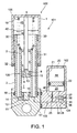
- the fork body 101 has a reservoir chamber 106 partially filled with gas.
- the fork body 101 has an upper end connected to a side of the handlebar in the two-wheeled vehicle (not shown) and a lower end connected to a side of the front wheel in the two-wheel vehicle, and performs the expansion and contraction operation in a telescoping manner.
- the fork body 101 is provided with an outer tube 1 as a vehicle-side tube connected to the handlebar, an inner tube 2 as an axle-side tube connected to the front wheel and fitted so as to slide into the outer tube 1, and a damper portion 105 provided in the inner tube 2 and generating a damping force caused by a relative movement of the outer tube 1 and the inner tube 2.
- the inner tube 2 is formed in a tubular shape, and inserted through ring-shaped bearings 30, 31 into the outer tube 1 similarly formed in a tubular shape with allowance for sliding therein.
- a ring-shaped seal member 32 is provided between an inner periphery of an opening end of the outer tube 1 and an outer periphery of the inner tube 2.
- the damper portion 105 is provided with a cylinder 3 mounted on the bottom portion of the inner tube 2 and filled with hydraulic oil, a piston 4 slidably placed in the cylinder 3 and dividing the inside of the cylinder 3 into first and second oil chambers 6 and 7, and a rod 5 having one end connected to the piston 4 and the other end connected to the outer tube 1.
- the piston 4 slides in the cylinder 3 when the outer tube 1 moves along the inner tube 2.
- the first oil chamber 6 and the second oil chamber 7 communicate with each other by means of passages 8, 9 provided in the piston 4.
- the reservoir chamber 106 is formed in a space defined by the outer tube 1 and the inner tube 2, that is, outside the damper portion 105.
- the second oil chamber 7 in the cylinder 3 communicates with the reservoir chamber 106 by means of passages 10, 11 which are formed at a lower end of the cylinder 3.
- Damping-force generator mechanisms 13, 14, such as an orifice and a leaf valve, are provided in the respective passages 8 and 10.
- a check valve 15 is provided in the passage 9 to block the flow of the hydraulic oil from the first oil chamber 6 to the second oil chamber 7.
- a check valve 16 is provided in the passage 11 to block the flow of the hydraulic oil from the second oil chamber 7 to the reservoir chamber 106.
- the lower ends of the cylinder 3 and the inner tube 2 are coupled to a bracket 17 connected to the axle of the two-wheeled vehicle and are sealed.
- the passages 10, 11 are formed in the bracket 17.
- a ring-shaped seal member 18 is provided between the bracket 17 and the inner tube 2.
- the seal member 18 and the seal member 32 seal the space defined by the outer tube 1 and the inner tube 2.
- the reservoir tank 102 is partially filled with gas, and communicates with the reservoir chamber 106 of the fork body 101 by means of the passage 103.
- the reservoir tank 102 is provided inside the housing 20 connected to a side portion of the bracket 17.
- the reservoir tank 102 includes an oil chamber 23 and a gas chamber 44 which are defined by a free piston housed and slidably attached to a hollow portion 21 formed in the housing 20.
- the housing 20 is coupled to the side of the bracket 17, so that the expansion and contraction operation of the fork body 101 is not impeded by the bracket 17.
- the flow path 103 is provided in the bracket 17 and the housing 20, and is constituted of passages 24, 25 which establish parallel communication between the oil chamber 12 of the fork body 101 and the oil chamber 23 of the reservoir tank 102. Thereby, the oil chamber 23 of a reservoir tank 102 communicates also with the second oil chamber 7 of the damper portion 105 via the oil chamber 12 of the fork body 101.
- the flow adjusting apparatus 104 is equipped with an on-off valve 35 and a relief valve 40 in parallel with each other.
- the on-off valve 35 is mounted on the passage 24 to switch between the communication and shut-off modes of the passage 24.
- the relief valve 40 is mounted on the passage 25 to accept the flow of the hydraulic oil from the oil chamber 12 of the fork body 101 to the oil chamber 23 of the reservoir tank 102 when the pressure in the reservoir chamber 106 of the fork body 101 reaches a predetermined cracking pressure in a state of the on-off valve 35 blocking the passage 24.
- the on-off valve 35 and the relief valve 40 are placed in the housing 20.
- the on-off valve 35 is an electromagnetic on-off valve that includes a communication position 36, a shut-off position 37, a solenoid 38, and a spring 39 facing the solenoid 38.
- the opening of the on-off valve 35 may be adjusted to control a flow quantity of the hydraulic oil passing through the on-off valve 35.
- valve 40 Any type of valve may be used as the relief valve 40 as long as the valve has a function as a check valve and also has a mechanism for opening the valve under a predetermined cracking pressure.
- the adjustment of the cracking pressure of the relief valve 40 is performed by adjusting the load of the spring for urging the valve element.
- the inner tube 2 penetrates the outer tube 1, so that the volume of the reservoir chamber 106 is reduced. Further, the piston 4 of the damper portion 105 moves in a direction compressing the second oil chamber 7 in the cylinder 3, so that the hydraulic oil in the second oil chamber 7 flows through the passage 10 into the oil chamber 12 of the reservoir chamber 106. As a result, the volume of the gas chamber 43 bounded by the oil level 42 in the reservoir chamber 106 is reduced.
- the inner tube 2 leaves the inside of the outer tube 1, so that the volume of the reservoir chamber 106 is increased. Further, the piston 4 of the damper portion 105 moves in a direction expanding the second oil chamber 7 in the cylinder 3, so that the insufficient supply of hydraulic oil in the second oil chamber 7 is replenished from the oil chamber 12 of the reservoir chamber 106 through the passage 10. As a result, the volume of the gas chamber 43 bounded by the oil level 42 in the reservoir chamber 106 is increased.
- the expansion and contraction operation of the fork body 101 increases/decreases the volume of the gas chamber 43 in the reservoir chamber 106, so that the gas in the gas chamber 43 generates repulsion, or an air-spring force.
- the hydraulic oil flows through the damping-force generator mechanisms 13, 14 by the movement of the piston 4 in the cylinder 3, so that a pressure loss occurs. In this manner, a damping force in the opposite direction from the moving direction of the piston is generated in the damper portion 105.
- the oil chamber 23 expands/contracts because a portion of the hydraulic oil flows into the oil chamber 23 from the flow path 103 in accordance with the expansion and contraction operation of the fork body 101.
- the gas chamber 44 expands/contracts while moving the piston 22 upward/downward to produce an air-spring force.
- the oil chamber 12 of the fork body 101 and the oil chamber 23 of the reservoir tank 102 communicate with each other, so that the gas chamber 44 of the reservoir tank 102 becomes identical in pressure to the gas chamber 43 of the fork body 101.
- the front fork 100 uses the large gas-chamber volume of the gas chamber 43 and the gas chamber 44 in accordance with the expansion and contraction operation of the fork body 101 to produce an air-spring force. For this reason, the fork body 101 performs the expansion and contraction operation in a low reaction-force state as compared with the case when it performs the expansion and contraction operation by the use of the gas chamber 43 alone.
- the on-off valve 35 is set at the communication position 36 in order to cause the front fork 100 to produce a low air-spring force. In consequence, it is possible to provide an improvement of ride comfort on the vehicle.
- the on-off valve 35 is set to be switched to the shut-off position 37 in order to cause the front fork 100 to produce a high air-spring force. In consequence, the vehicle body is restrained from pitching forward, i.e. performing a so-called nose dive.
- the volume of the gas chamber 43 is set as a value smaller than the maximum amount of change in the inside volume of the fork body 101 which varies in accordance with the expanding and contraction operation of the fork body 101, the front fork 100 is capable of producing a very high air-spring force. In consequence, the effect of restraining the nose dive is enhanced.
- the relief valve 40 is provided in the passage 25 connecting the fork body 101 and the reservoir tank 102 as described above. For this reason, even when the fork body 101 performs the contraction operation with the on-off valve 35 kept in the shut-off position, the pressure in the fork body 101 is not built up abnormally and therefore, the contraction operation of the fork body 101 is not impeded. Further, there is no chance of a large load being applied to the seal member 32 offering a sealing operation between the outer tube 1 and the inner tube 2. This makes it possible to prevent oil leakage through the area between the outer tube 1 and the inner tube 2.
- the provision of the relief valve 40 brings about the avoidance of an impediment to the contraction operation of the front fork 100 and the oil leakage.
- the volume of the gas chamber 43 smaller than the maximum amount of change in the inside volume of the fork body 101 which varies when the fork body 101 performs the expansion and contraction operation.
- the predetermined cracking pressure of the relief valve 40 may be selectively decided in accordance with the specifications of the seal member 32 and the degree of restraint on the nose dive.
- a high reaction-force state is achieved by moving the on-off valve 35 to the shut-off position 37 and also when the high reaction-force exceeds a predetermined value, the high reaction-force can be reduced by the operation of the relief valve 40. Accordingly, when the front fork 100 is used as a hydraulic shock absorber mounted on the front wheel in a two-wheeled vehicle, a stable reduction in a change in vehicle attitude, or nose dive, occurring when a brake is applied to the two-wheeled vehicle becomes possible. Also, a low reaction-force state is achieved by switching the on-off shaft to the communication position 36. This makes it possible to improve ride comfort on the vehicle.
- the fork body 101 is designed as an invertible type in which the outer tube 1 is an upper-end member and the inner tube 2 is a lower-end member, but may be designed as a standard type in which the outer tube 1 is the lower-end member and the inner tube 2 is the upper-end member.
- the housing 20 may be put into a sideways position in the figure. Thereby, the mounting position of the front fork in the two-wheeled vehicle can be set at the optimum position.
- a bladder may be used instead of the free piston 22 of the reservoir tank 102.
- the bladder is out of sliding contact with the inner periphery of the hollow portion 21 as is the case with the free piston 22, and therefore, has the advantage of no occurrence of sliding resistance.
- the first preferred embodiment has described the case of moving the on-off valve 35 to the communication position 36 or the shut-off position 37, but the on-off valve 35 may be structured in such a way as to maintain the communication position 36 and to control the flow quantity.
- the hydraulic oil flows from the fork body 101 to the reservoir tank 102 under resistance.
- the air-spring force produced by the front fork 100 is larger than the air-spring force when the on-off valve 35 is fully opened and smaller than that when the on-off valve 35 is completely closed.
- the flow control being performed by adjusting the degree of valve opening of the on-off valve 35 makes it possible to adjust the air-spring force produced by the front fork 100, in continuous variations from maximum to minimum.
- the air-spring force produced by the front fork 100 is controlled so as to be at the optimum, resulting in an improvement in ride comfort on the two-wheeled vehicle.
- the need to use a pneumatic source such as a pneumatic pump to change the air-spring pressure is eliminated, leading to energy saving, space saving, and an improvement in mountability on the vehicle.
- FIG. 2 is a schematic view showing the front fork 200. Note that the same structure as that in the first preferred embodiment is designated by the same reference numerals and the description is omitted.
- the front fork 200 of the second preferred embodiment is equipped with an on-off valve 35 and a relief valve 40 as the flow adjustment apparatus 104 for adjusting a flow of hydraulic oil between an oil chamber 12 of a front fork 101 and an oil chamber 23 of a reservoir tank 102, and further a check valve 41 that accepts only a flow of hydraulic oil from the reservoir tank 102 toward a reservoir chamber 106 of the fork body 101.
- the check valve 41 is provided in a passage 26 communicating with a passage 24 and bypassing the on-off valve 35. Note that the check valve 40 is placed in the housing 20 and structured together with the on-off valve 35 and the relief valve 40 as an assembly.
- the fork body 101 When hard braking is applied to the two-wheeled vehicle, the fork body 101 performs the contraction operation, and then shifts to the expansion operation. At this point, the front fork 200 comes into a high reaction-force state by switching the on-off valve 35 to the shut-off position 37 on the braking of the two-wheeled vehicle, to reduce the nose dive phenomenon. However, if the fork body 101 shifts to the expansion operation during the high reaction-force state, the vehicle body rises high in the air due to reaction.
- the gas-chamber volume of the entire front fork 200 in the expansion operation of the fork body 101 increases, to decrease the air-spring force to be produced by the front fork 200.
- the front fork 200 performs the contraction operation in the high reaction-force state when braking is applied, and then when shifting to the expansion operation, the front fork 200 switches to the low reaction-force state.
- the operation of the check valve 41 allows the fork body 101 to perform the expansion operation in the low reaction-force state. Accordingly it is possible to restrain the vehicle body from rising in the air due to reaction to a nose dive. In consequence, an improvement in ride comfort on the vehicle is possible even after a nose dive, without a feeling of being jerked upward being produced in the rider who holds the handlebar of a two-wheeled vehicle.
- the same operational advantages can be obtained as in the case of using the check valve 41.
- control such as a change in the switching timing of the on-off valve 35 dependent upon the degree of the nose dive.
- the air-spring force produced by the front fork 200 is mechanically reduced. In consequence, the front fork 200 can be manufactured at low costs and the response is satisfactory.
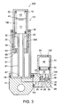
- FIG. 3 is a diagram conceptually illustrating the front fork 300. Note that the same structure as that in the first and second preferred embodiments is designated by the same reference numerals and the description is omitted.
- Differences between the front fork 300 of the third preferred embodiment and the front fork 200 of the second preferred embodiment lie in that the front fork 200 has the outer tube 1 connected to the side of the vehicle body and the inner tube 2 connected to the side of the axle, but the front fork 300 has an outer tube 51 connected to a side of an axle and an inner tube 52 connected to the side of the vehicle body, and in the structure of a damper portion.
- a damper portion 305 in the front fork 300 includes a hollow pipe 61 standing in an axial core portion of the bottom of the outer tube 51, a piston 62 provided on the outer periphery of an upper end of the hollow pipe 61 and in sliding contact with the inner periphery of the inner tube 52, an auxiliary piston 63 provided on the inner periphery of a lower end of the inner tube 52 and in sliding contact with the outer periphery of the hollow pipe 61, and a first oil chamber 64 defined by the inner tube 52, the hollow pipe 61, the piston 62 and the auxiliary piston 63.
- a bore 67 is formed in a lower portion of the side of the hollow pipe 61 for communication between the inside and the outside of the hollow pipe 61.
- the first chamber 64 communicates with the reservoir chamber 106 of the fork body 101 by means of the bore 67.
- the oil chamber 23 of the reservoir tank 102 communicates with the inside of the hollow pipe 61, that is, the reservoir chamber 106 of the fork body 101, by means of the flow path 103. Further, the oil chamber 23 communicates with the inside of the damper portion 305 by means of the bore 67.
- the switching operation of the on-off valve 35 allows the switching of the gas-chamber volume of the entire front fork 300 between the total volume of the gas chamber 43, 44 and the volume of the gas chamber 43 alone. Accordingly, as in the case of the front fork 100 of the first preferred embodiment, the air-spring force produced by the front fork 300 is able to be adjusted by the operation of the on-off valve 35.
- the outer tube 51 may be placed in a portion at the vehicle-body end and the inner tube 52 may be placed in a portion at the axle end.
- gas possibly enters the first oil chamber 64, it is preferable to provide the passage 65 and the orifice 66 in the piston 62.
- FIG. 4 is a schematic view showing the front fork 400. Note that the same structure as that in the first and second embodiments 1 and 2 is designated by the same reference numerals and the description is omitted.
- Differences between the front fork 400 of the fourth preferred embodiment and the front fork 200 of the second preferred embodiment lie in that the housing 20 incorporating an assembly including a reservoir tank 102, an on-off valve 35, a relief valve 40 and a check valve 41 is connected to the outer tube 1.
- a bore 50 is drilled in the side wall of the outer tube 1 and the housing 20 is connected to the side portion of the outer tube 1 such that the bore 50 and a flow path 103 communicate.
- a nick 30a is formed in a bearing 30 for communication between the reservoir tank 102 and a clearance between the outer tube 1 and the inner tube 2 communicates with the reservoir chamber 106 of the fork body 101 by means of the nick 30a.
- the reservoir chamber 106 is also formed in a space between the outer tube 1 and the inner tube 2.
- the reservoir tank 102, the on-off valve 35, the relief valve 40 and the check valve 41 are combined together as an assembly and incorporated in the housing 20. Therefore, it is possible to connect the housing 20 to the optimum position appropriate to the outer tube 1 or the inner tube 2. Thereby, the mounting position of a front fork on a two-wheeled vehicle is able to be set at the optimum position.
- the housing 20 can be provided at the upper end of the outer tube 1.
- a passage is formed in a rod 5 to communicate with the first oil chamber 6 or the second oil chamber 7 and a flow path 103 may be connected to the passage.
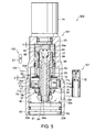
- Differences between the front fork 500 of the fifth preferred embodiment and the front fork 200 of the second preferred embodiment lie in that the front fork 200 has the on-off valve 35, the relief valve 40 and the check valve 41 individually provided in the respective passages 24, 25 and 26 which are arranged in parallel, but in the front fork 500, an on-off valve, a relief valve and a check valve are structured as a valve mechanism 501 provided in a flow path 103.
- the valve mechanism 501 is provided in the flow path 103 establishing communication between a fork body 101 and a reservoir tank 102.
- the valve mechanism 501 is set as a normally opening type that accepts a flow of hydraulic oil in the flow path 103 when a solenoid is not energized and blocks the flow of hydraulic oil in the flow path 103 when the solenoid is energized.
- the partition wall 71 is a ring-shaped member placed with its outer periphery being in liquid-tight relation to the inner periphery of the housing 20, and divides the inside of the housing 20 into top and bottom in Fig. 5, that is, a portion on the fork body 101 side and a portion on the reservoir tank 102 side.
- the partition wall 71 has an outer-periphery angled portion 71f engaged with a step portion 20a formed on the inner periphery of the housing 20.
- the partition wall 71 is set in a predetermined position by an urging spring 82 having a base end engaged with a cap 81.
- the urging spring 82 serves also as a spacer. Therefore, the urging spring 82 is not limited to a spring member, and may be a tubular element having an opening formed in its barrel corresponding to a communicating hole 20c.
- the partition wall 71 is constituted of a first partition-wall portion 71a having a step portion 71d on the reservoir tank 102 side and a second partition-wall portion 71b having a step portion 71e on the fork body 101 side.
- the valve element 72 is placed for closure on the reservoir tank 102 side of the partition wall 71 and the check valve 75 is placed for closure on the fork body 101 side of the partition wall 71.
- the valve element 72 is able to block only a first communicating path 76a as a predetermined communicating path of the plurality communicating paths 76 which is formed in the first partition-wall portion 71a.
- the check valve 75 is placed to block, when necessary, a second communicating path 76b of the plurality of communicating paths 76 formed in the second partition-wall portion 71b, that is, the communicating path 76 which the valve element 72 is incapable of blocking.
- the cap 81 is provided for blocking the opening of the lower end of the housing 20 while keeping it in a liquid-tight state, and is set in a predetermined position by fitting a snap ring 83 formed on the outer periphery of the cap 81 into the inner periphery of the opening end 20b of the housing 20.
- the valve element 72 which is a laminated leaf valve, faces a valve seat face 71c on the reservoir tank 102 side of the partition wall 71, and is placed, slidably in the vertical direction in Fig. 5, on the outer periphery of a guide cylinder 85 mounted on the outer periphery of a center rod 84 which extends through the axial core portion of the partition wall 71 in the vertical direction in Fig. 5.
- the valve element 72 is capable of opening/closing the first communicating path 76a of the communicating paths 76.
- valve element 72 is a laminated leaf valve, if a pressure difference between upstream and downstream from the valve element 72 exceeds a predetermined value in a state in which the valve element 72 blocks the first communicating path 76a and an oil pressure from the reservoir chamber 106 acts (see Fig. 6), the valve element 72 performs a relief operation in which the vicinity of the outer periphery of the valve element 72 fluctuates to introduce hydraulic oil from the oil chamber 12 of the fork body 101 toward the oil chamber 23 of the reservoir tank 102. In this manner, the valve mechanism 501 makes the valve element 72 perform the operation as a relief valve.
- the piston portion 73 which is a tubular member, is disposed movably on the outer periphery of the guide cylinder 85 in the longitudinal direction and behind the valve element 72 in series, to drive the valve element 72 in the closing direction.
- the piston portion 73 drives the valve element 72 in the closing direction by an external force acting on the rear face of the piston portion 73. This corresponds to the thrust from the solenoid 74 and the oil pressure from the fork body 101, which will be described later.
- a lower end of the piston portion 73 is in contact with the rear face of the valve element 72 via a washer 91. Note that the lower end of the piston portion 73 may be in direct contact with the rear face of the valve element 72.
- the solenoid 74 is fixed to the head portion of the housing 20 and has an output shaft 92, which is a plunger, penetrating the housing 20 and disposed in the housing 20. Note that the solenoid 74 may be housed in and attached to the housing 20, or alternatively may be housed in and attached to a casing incorporated in the housing 20.
- the amount of movement of the output shaft 92 produced by the thrust of the solenoid 74 is a slight stroke shown by reference letter "D" in Fig. 5. A description will be given later of the reason why such a slight stroke is sufficient as the amount of movement of the output shaft 92 produced by the thrust of the solenoid 74 in the present invention.
- the thrust of the solenoid 74 is transferred to the piston portion 73 by a thrust transmission mechanism structured as follows.
- the thrust transmission mechanism includes a MAS element 93 which is placed in contact with the leading end of the output shaft 92 in the solenoid 74 so as to cover an upper end of a center rod 84, and a plurality of guide rods 94 provided in a lower end of the MAS element 93 in a connected arrangement and extending along the center rod 84.
- Each of the lower ends of the plurality of guide rods 94 is in contact with the piston portion 73. Accordingly, when the solenoid 74 is energized, the MAS element 93 is moved down by the solenoid thrust, and in synchronism with this the guide rods 94 move down, so that the piston portion 73 presses the valve element 72 in the closing direction.
- the oil pressure acting on the rear face of the piston portion 73 is described.
- the oil pressure from the fork body 101 designed to act on the rear face of the piston portion 73 is transferred to the piston portion 73 by an oil-pressure transmission mechanism.
- the oil-pressure transmission path 97 is established by the arrangement in which the holder member 95 also serves as the partition wall and the outer periphery of the holder member 95 is placed in liquid-tight relation to the inner periphery of the housing 20.
- the oil-pressure transmission path 97 is able to cause the hydraulic oil flowing from the fork body 101 toward the reservoir tank 102 to diverge upstream from the partition wall 71 so as to introduce a branch flow toward the rear face of the piston portion 73.
- valve mechanism 501 When the solenoid 74 is not energized, no external force acts on the valve element 72. Therefore, the flow of hydraulic oil from the fork body 101 toward the reservoir tank 102 lifts the valve element 72 up to the opening position.
- the solenoid 74 When the solenoid 74 is energized, the solenoid 74 drives the valve element 72 via the piston portion 73 in the closing direction in opposition to the flow of hydraulic oil from the fork body 101 toward the reservoir tank 102. Thereby, the valve element 72 moves closer to the seat face 71c of the first partition wall portion 71a. Then, due to the hydraulic oil flowing from the fork body 101 toward the reservoir tank 102, a pressure difference between the upstream and the downstream of the valve element 72 is produced. In other words, the pressure upstream of the valve element 72 builds up.
- valve element 72 When the pressure upstream of the valve element 72 increases because of the pressure difference between after and before the valve element 72, the hydraulic oil upstream of the valve element 72 flows into the oil-pressure transmission path 97. Thereby, the oil pressure upstream of the valve element 72 acts on the rear face of the piston portion 73 to cause the piston portion 73 to press the valve element 72 in the closing direction. Then, the valve element 72 is driven again in the closing direction and seated on the seat face 71c of the first partition wall portion 71a of the partition wall 71 so as to block the first communicating path 76a, so that the communication between the fork body 101 and the reservoir tank 102 is disconnected. In this way, the reason why valve element 72 is closed by the pressure upstream of the valve element 72 is because the effective pressure area of the piston portion 73 in the closing direction is set larger than the effective pressure area of the valve element 72 in the opening direction.
- valve element 72 moves a larger stroke length to perform the closing operation as shown by a reference letter "D1" in Fig. 6 as compared with the amount of movement "D" of the output shaft 92 caused by the solenoid thrust. This is because the valve element 72 is acted upon by the oil pressure with the solenoid thrust.
- valve element 72 When the solenoid 74 is changed from the energization state to the non-energization state, the valve element 72 is moved in the opening direction by the oil pressure from the fork body 101 to open the first communicating path 76a.
- valve mechanism 501 causes a reduction in size of the solenoid 74 because the flow path 103 is completely blocked only by slightly moving the plunger of the solenoid 74. Further, the functions in all of an on-off valve, a relief valve and a check valve are achieved by the single flow path 103. This causes a reduction in size of the hydraulic-oil adjusting apparatus interposed between the fork body 101 and the reservoir tank 102. In consequence, a reduction in size of the front fork 500 with the valve mechanism 501 is also possible.
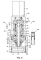
- a valve mechanism 601 in the front fork 600 includes a first valve mechanism 602 having the functions as the on-off valve and the relief valve and a second valve mechanism 603 having the function as the check valve.
- the first valve mechanism 602 and the second valve mechanism 603 are respectively provided in two flow paths 103a, 103b which are arranged in parallel.
- the first valve mechanism 602 includes: a valve element 72 placed to block, when necessary, all of a plurality of communicating paths 76 provided in a partition wall 71; a center rod 84 penetrating through an axial core portion of the valve element 72 so as to support the valve element 72; a piston portion 73 engaging with the center rod 84 and driving via the center rod 84 the valve element 72 in the closing direction; and an urging spring 58 attached to the center rod 84 so as to urge the valve element 72 in the opening direction.
- valve element 72 is a laminated leaf valve, in the conditions that the valve element 72 bocks all the communicating paths 76 and the oil pressure from the fork body 101 acts, when the pressure difference between the upstream and the downstream of the valve element 72 exceeds a predetermined value, the valve element 72 performs a relief operation of fluctuating to accept the flow of hydraulic oil from the fork body 101 toward the reservoir tank 102.
- the second valve mechanism 603 includes: a partition wall 59 for isolating the flow path 103; a plurality of communicating paths 59a penetrating through the partition wall 59 to establish communication between an oil chamber 12 in the fork body 101 and an oil chamber 23 in the reservoir tank 102; a check valve 75 placed so as to block, when necessary, all the plurality of communicating paths 59a; and a non-return spring 56 urging the check valve 75 in the closing direction.
- the check valve 75 Since the check valve 75 is positioned opposite the partition wall 59 from the fork body 101, the check valve 75 is placed in the state of being acted upon by the oil pressure from the reservoir tank 102 and operates to accept only the flow of hydraulic oil from the reservoir tank 102 toward the fork body 101.
Applications Claiming Priority (4)
| Application Number | Priority Date | Filing Date | Title |
|---|---|---|---|
| JP2004356380A JP4541119B2 (ja) | 2004-12-09 | 2004-12-09 | 懸架装置 |
| JP2005031184 | 2005-02-08 | ||
| JP2005139410A JP4733423B2 (ja) | 2005-02-08 | 2005-05-12 | 開閉弁構造 |
| JP2005189606A JP2007009979A (ja) | 2005-06-29 | 2005-06-29 | フロントフォーク |
Publications (3)
| Publication Number | Publication Date |
|---|---|
| EP1669283A2 true EP1669283A2 (de) | 2006-06-14 |
| EP1669283A3 EP1669283A3 (de) | 2007-05-23 |
| EP1669283B1 EP1669283B1 (de) | 2008-09-24 |
Family
ID=35976464
Family Applications (1)
| Application Number | Title | Priority Date | Filing Date |
|---|---|---|---|
| EP05026747A Expired - Fee Related EP1669283B1 (de) | 2004-12-09 | 2005-12-07 | Vorderradgabel |
Country Status (3)
| Country | Link |
|---|---|
| US (1) | US7441638B2 (de) |
| EP (1) | EP1669283B1 (de) |
| DE (1) | DE602005009911D1 (de) |
Families Citing this family (53)
| Publication number | Priority date | Publication date | Assignee | Title |
|---|---|---|---|---|
| KR100698604B1 (ko) * | 1998-12-18 | 2007-03-21 | 리차드 부가즈 | 완충장치 |
| US8464850B2 (en) | 2006-11-16 | 2013-06-18 | Fox Factory, Inc. | Gas spring curve control in an adjustable-volume gas-pressurized device |
| US10941828B2 (en) | 2002-06-25 | 2021-03-09 | Fox Factory, Inc. | Gas spring with travel control |
| US7703585B2 (en) | 2002-06-25 | 2010-04-27 | Fox Factory, Inc. | Integrated and self-contained suspension assembly having an on-the-fly adjustable air spring |
| US20080296814A1 (en) | 2002-06-25 | 2008-12-04 | Joseph Franklin | Gas spring with travel control |
| US7963509B2 (en) | 2007-01-31 | 2011-06-21 | Fox Factory, Inc. | Travel control for a gas spring and gas spring having very short travel modes |
| SE528606C2 (sv) * | 2005-10-19 | 2006-12-27 | Oehlins Racing Ab | Anordning vid teleskopgaffelben för terränggående fordon |
| US7497452B2 (en) * | 2006-06-02 | 2009-03-03 | Husco International, Inc. | Hydro-pneumatic vehicle suspension system with a double acting cylinder and accumulators |
| DE602006005365D1 (de) * | 2006-09-13 | 2009-04-09 | Horstman Defence Systems Ltd | Aufhängungsvorrichtung |
| JP4898386B2 (ja) * | 2006-10-27 | 2012-03-14 | カヤバ工業株式会社 | フロントフォーク |
| FR2908485B1 (fr) * | 2006-11-13 | 2012-06-15 | Messier Dowty Sa | Amortisseur compact pour atterrisseur d'aeronef, et atterrisseur comportant un tel amortisseur |
| US8869959B2 (en) | 2008-07-24 | 2014-10-28 | Fox Factory, Incorporated | Vehicle suspension damper |
| US9156325B2 (en) * | 2008-03-19 | 2015-10-13 | Fox Factory, Inc. | Methods and apparatus for vehicle suspension having multiple gas volumes |
| US20100244340A1 (en) | 2008-03-19 | 2010-09-30 | Wootten Dennis K | Methods and apparatus for combined variable damping and variable spring rate suspension |
| US20100170760A1 (en) | 2009-01-07 | 2010-07-08 | John Marking | Remotely Operated Bypass for a Suspension Damper |
| US10060499B2 (en) | 2009-01-07 | 2018-08-28 | Fox Factory, Inc. | Method and apparatus for an adjustable damper |
| US8857580B2 (en) | 2009-01-07 | 2014-10-14 | Fox Factory, Inc. | Remotely operated bypass for a suspension damper |
| US9239090B2 (en) * | 2009-01-07 | 2016-01-19 | Fox Factory, Inc. | Suspension damper with remotely-operable valve |
| US11306798B2 (en) | 2008-05-09 | 2022-04-19 | Fox Factory, Inc. | Position sensitive suspension damping with an active valve |
| US9033122B2 (en) | 2009-01-07 | 2015-05-19 | Fox Factory, Inc. | Method and apparatus for an adjustable damper |
| US10047817B2 (en) | 2009-01-07 | 2018-08-14 | Fox Factory, Inc. | Method and apparatus for an adjustable damper |
| US8627932B2 (en) | 2009-01-07 | 2014-01-14 | Fox Factory, Inc. | Bypass for a suspension damper |
| US9452654B2 (en) | 2009-01-07 | 2016-09-27 | Fox Factory, Inc. | Method and apparatus for an adjustable damper |
| US8393446B2 (en) | 2008-08-25 | 2013-03-12 | David M Haugen | Methods and apparatus for suspension lock out and signal generation |
| US10036443B2 (en) | 2009-03-19 | 2018-07-31 | Fox Factory, Inc. | Methods and apparatus for suspension adjustment |
| US9140325B2 (en) | 2009-03-19 | 2015-09-22 | Fox Factory, Inc. | Methods and apparatus for selective spring pre-load adjustment |
| US9422018B2 (en) | 2008-11-25 | 2016-08-23 | Fox Factory, Inc. | Seat post |
| US10821795B2 (en) | 2009-01-07 | 2020-11-03 | Fox Factory, Inc. | Method and apparatus for an adjustable damper |
| US11299233B2 (en) | 2009-01-07 | 2022-04-12 | Fox Factory, Inc. | Method and apparatus for an adjustable damper |
| US9038791B2 (en) | 2009-01-07 | 2015-05-26 | Fox Factory, Inc. | Compression isolator for a suspension damper |
| US9556925B2 (en) | 2009-01-07 | 2017-01-31 | Fox Factory, Inc. | Suspension damper with by-pass valves |
| US8936139B2 (en) | 2009-03-19 | 2015-01-20 | Fox Factory, Inc. | Methods and apparatus for suspension adjustment |
| US8838335B2 (en) | 2011-09-12 | 2014-09-16 | Fox Factory, Inc. | Methods and apparatus for suspension set up |
| EP3919298A1 (de) * | 2009-05-04 | 2021-12-08 | Fox Factory, Inc. | Aufhängungssystem für ein fahrzeug |
| JP5545710B2 (ja) * | 2009-09-08 | 2014-07-09 | ヤマハ発動機株式会社 | クッション装置および自動二輪車 |
| US8672106B2 (en) | 2009-10-13 | 2014-03-18 | Fox Factory, Inc. | Self-regulating suspension |
| US8955653B2 (en) | 2009-10-13 | 2015-02-17 | Fox Factory, Incorporated | Methods and apparatus for controlling a fluid damper |
| US8763770B2 (en) | 2011-03-03 | 2014-07-01 | Fox Factory, Inc. | Cooler for a suspension damper |
| US10697514B2 (en) | 2010-01-20 | 2020-06-30 | Fox Factory, Inc. | Remotely operated bypass for a suspension damper |
| EP3778358B1 (de) | 2010-07-02 | 2023-04-12 | Fox Factory, Inc. | Einstellbare sattelstütze mit positiver verriegelung |
| CN101943238B (zh) * | 2010-09-08 | 2012-10-10 | 河海大学常州校区 | 双溢流液压阻尼器 |
| US9127738B2 (en) * | 2011-03-14 | 2015-09-08 | Oshkosh Defense, Llc | Damper assembly |
| EP2530355B1 (de) | 2011-05-31 | 2019-09-04 | Fox Factory, Inc. | Vorrichtungen für lageempfindliche und/oder anpassbare Aufhängungsdämpfung |
| US11279199B2 (en) * | 2012-01-25 | 2022-03-22 | Fox Factory, Inc. | Suspension damper with by-pass valves |
| US10330171B2 (en) | 2012-05-10 | 2019-06-25 | Fox Factory, Inc. | Method and apparatus for an adjustable damper |
| JP6417281B2 (ja) * | 2015-06-10 | 2018-11-07 | Kyb株式会社 | 緩衝器 |
| US10118456B2 (en) * | 2016-01-11 | 2018-11-06 | David Perrault | Load leveling emulsion suspension system |
| US10737546B2 (en) | 2016-04-08 | 2020-08-11 | Fox Factory, Inc. | Electronic compression and rebound control |
| US10214071B1 (en) * | 2016-05-28 | 2019-02-26 | PAL Suspension LLC | Vehicle suspension system with multi-stage hydraulic cylinder assemblies and external spring packs |
| US11009093B2 (en) * | 2017-10-16 | 2021-05-18 | Suspension Direct, Inc. | Electronically adjustable shock absorber |
| JP7212552B2 (ja) * | 2019-03-04 | 2023-01-25 | Kyb株式会社 | 緩衝器 |
| JP7084888B2 (ja) * | 2019-03-04 | 2022-06-15 | Kyb株式会社 | 緩衝器 |
| DE102019212908A1 (de) * | 2019-08-28 | 2021-03-04 | Thyssenkrupp Ag | Schwingungsdämpfer mit verstellbarer Dämpfkraft |
Citations (2)
| Publication number | Priority date | Publication date | Assignee | Title |
|---|---|---|---|---|
| JPS53151061U (de) * | 1977-04-30 | 1978-11-28 | ||
| US20020121416A1 (en) * | 2001-02-19 | 2002-09-05 | Yohei Katayama | Hydraulic cylinder apparatus |
Family Cites Families (12)
| Publication number | Priority date | Publication date | Assignee | Title |
|---|---|---|---|---|
| US4091897A (en) * | 1977-06-24 | 1978-05-30 | Chicago Bridge & Iron Company | Hydraulic counterweight and shock-absorbing system |
| DE3019668A1 (de) | 1980-05-22 | 1981-11-26 | SIEMENS AG AAAAA, 1000 Berlin und 8000 München | Geraet zum erfassen und verarbeiten von elektrischen signalen |
| US4506751A (en) * | 1982-12-21 | 1985-03-26 | Applied Power Inc. | Tilt cab truck with anti-dive and anti-sway control |
| US4695226A (en) * | 1983-11-07 | 1987-09-22 | United Technologies Corporation | Helicopter rotor backup damper system |
| DE3524863A1 (de) * | 1985-04-12 | 1986-10-30 | Robert Bosch Gmbh, 7000 Stuttgart | Verfahren und vorrichtung zum steuern der federhaerte, insbesondere bei fahrzeugen |
| DE3937606A1 (de) * | 1989-11-11 | 1991-05-16 | Daimler Benz Ag | Drehvorrichtung zum verdrehen der kolbenstange eines zylinderaggregates |
| US5480011A (en) * | 1992-09-29 | 1996-01-02 | Showa Corp. | Hydraulic damper |
| JP3280725B2 (ja) * | 1992-12-02 | 2002-05-13 | オーリンス レーシング アクティエ ボラーグ | 筒型ショックアブソーバ |
| JPH09310731A (ja) * | 1996-05-21 | 1997-12-02 | Tokico Ltd | 油圧緩衝器 |
| JPH10338017A (ja) * | 1997-04-11 | 1998-12-22 | Tokico Ltd | シリンダ装置および車高調整装置 |
| DE19849222B4 (de) * | 1998-10-26 | 2004-02-12 | Zf Sachs Ag | Selbstpumpendes hydropneumatisches Federbein mit innerer Niveauregelung |
| DE60116246T2 (de) * | 2001-01-29 | 2006-07-13 | Ford Global Technologies, LLC, Dearborn | Federvorrichtung |
-
2005
- 2005-12-01 US US11/290,492 patent/US7441638B2/en active Active
- 2005-12-07 EP EP05026747A patent/EP1669283B1/de not_active Expired - Fee Related
- 2005-12-07 DE DE602005009911T patent/DE602005009911D1/de active Active
Patent Citations (2)
| Publication number | Priority date | Publication date | Assignee | Title |
|---|---|---|---|---|
| JPS53151061U (de) * | 1977-04-30 | 1978-11-28 | ||
| US20020121416A1 (en) * | 2001-02-19 | 2002-09-05 | Yohei Katayama | Hydraulic cylinder apparatus |
Also Published As
| Publication number | Publication date |
|---|---|
| US7441638B2 (en) | 2008-10-28 |
| US20060124414A1 (en) | 2006-06-15 |
| EP1669283A3 (de) | 2007-05-23 |
| EP1669283B1 (de) | 2008-09-24 |
| DE602005009911D1 (de) | 2008-11-06 |
Similar Documents
| Publication | Publication Date | Title |
|---|---|---|
| EP1669283B1 (de) | Vorderradgabel | |
| EP1820996B1 (de) | Dämpfungskraft-Regelventil und Stoßdämpfer, der es benutzt | |
| JP5034074B2 (ja) | 減衰力調整式流体圧緩衝器 | |
| KR101441513B1 (ko) | 쇽업소바 | |
| EP3115637B1 (de) | Dämpfungskraftvariabler stossdämpfer | |
| EP2110300B1 (de) | Vordergabel | |
| EP2487384B1 (de) | Hydraulische stossdämpfervorrichtung | |
| EP3067584A1 (de) | Fahrzeugaufhängungssystem | |
| CN113498396B (zh) | 缓冲器 | |
| US6729446B2 (en) | Solenoid-operated driving apparatus and damping force control type hydraulic shock absorber using the same | |
| JP2010084831A (ja) | 緩衝器 | |
| EP1502777B1 (de) | Selbstnivellierender Fahrzeugradaufhängungsdämpfer | |
| JP2008089037A (ja) | 減衰力調整式油圧緩衝器 | |
| JP2001180245A (ja) | 車両用懸架装置 | |
| US9849934B2 (en) | Shock absorber | |
| JP4748017B2 (ja) | 減衰力調整式油圧緩衝器 | |
| JP5368858B2 (ja) | ダンパ | |
| CN113474245B (zh) | 缓冲器 | |
| JPH07197975A (ja) | 車両用油圧緩衝器の減衰力発生装置 | |
| JP2006151161A (ja) | エアバネおよび懸架装置 | |
| US20190128360A1 (en) | Damping force-adjusting valve and shock absorber | |
| JP7308377B1 (ja) | 緩衝器 | |
| GB2378231A (en) | A damper for a vehicle suspension with externally mounted semi-active system | |
| JPH1191331A (ja) | サスペンション装置 | |
| KR20080081484A (ko) | 감쇠력 가변식 쇽업소버 |
Legal Events
| Date | Code | Title | Description |
|---|---|---|---|
| PUAI | Public reference made under article 153(3) epc to a published international application that has entered the european phase |
Free format text: ORIGINAL CODE: 0009012 |
|
| 17P | Request for examination filed |
Effective date: 20051207 |
|
| AK | Designated contracting states |
Kind code of ref document: A2 Designated state(s): AT BE BG CH CY CZ DE DK EE ES FI FR GB GR HU IE IS IT LI LT LU LV MC NL PL PT RO SE SI SK TR |
|
| AX | Request for extension of the european patent |
Extension state: AL BA HR MK YU |
|
| PUAL | Search report despatched |
Free format text: ORIGINAL CODE: 0009013 |
|
| AK | Designated contracting states |
Kind code of ref document: A3 Designated state(s): AT BE BG CH CY CZ DE DK EE ES FI FR GB GR HU IE IS IT LI LT LU LV MC NL PL PT RO SE SI SK TR |
|
| AX | Request for extension of the european patent |
Extension state: AL BA HR MK YU |
|
| AKX | Designation fees paid |
Designated state(s): DE FR GB IT |
|
| GRAP | Despatch of communication of intention to grant a patent |
Free format text: ORIGINAL CODE: EPIDOSNIGR1 |
|
| GRAS | Grant fee paid |
Free format text: ORIGINAL CODE: EPIDOSNIGR3 |
|
| GRAA | (expected) grant |
Free format text: ORIGINAL CODE: 0009210 |
|
| AK | Designated contracting states |
Kind code of ref document: B1 Designated state(s): DE FR GB IT |
|
| REG | Reference to a national code |
Ref country code: GB Ref legal event code: FG4D |
|
| REF | Corresponds to: |
Ref document number: 602005009911 Country of ref document: DE Date of ref document: 20081106 Kind code of ref document: P |
|
| PLBE | No opposition filed within time limit |
Free format text: ORIGINAL CODE: 0009261 |
|
| STAA | Information on the status of an ep patent application or granted ep patent |
Free format text: STATUS: NO OPPOSITION FILED WITHIN TIME LIMIT |
|
| 26N | No opposition filed |
Effective date: 20090625 |
|
| REG | Reference to a national code |
Ref country code: FR Ref legal event code: PLFP Year of fee payment: 11 |
|
| REG | Reference to a national code |
Ref country code: DE Ref legal event code: R082 Ref document number: 602005009911 Country of ref document: DE Representative=s name: GRUENECKER PATENT- UND RECHTSANWAELTE PARTG MB, DE Ref country code: DE Ref legal event code: R081 Ref document number: 602005009911 Country of ref document: DE Owner name: KYB CORPORATION, JP Free format text: FORMER OWNER: KAYABA INDUSTRY CO., LTD., TOKYO, JP |
|
| REG | Reference to a national code |
Ref country code: FR Ref legal event code: CD Owner name: KYB CORPORATION, JP Effective date: 20160321 Ref country code: FR Ref legal event code: CA Effective date: 20160321 |
|
| REG | Reference to a national code |
Ref country code: FR Ref legal event code: PLFP Year of fee payment: 12 |
|
| REG | Reference to a national code |
Ref country code: FR Ref legal event code: PLFP Year of fee payment: 13 |
|
| PGFP | Annual fee paid to national office [announced via postgrant information from national office to epo] |
Ref country code: DE Payment date: 20181210 Year of fee payment: 14 |
|
| PGFP | Annual fee paid to national office [announced via postgrant information from national office to epo] |
Ref country code: GB Payment date: 20181218 Year of fee payment: 14 Ref country code: FR Payment date: 20181220 Year of fee payment: 14 |
|
| PGFP | Annual fee paid to national office [announced via postgrant information from national office to epo] |
Ref country code: IT Payment date: 20181220 Year of fee payment: 14 |
|
| REG | Reference to a national code |
Ref country code: DE Ref legal event code: R119 Ref document number: 602005009911 Country of ref document: DE |
|
| GBPC | Gb: european patent ceased through non-payment of renewal fee |
Effective date: 20191207 |
|
| PG25 | Lapsed in a contracting state [announced via postgrant information from national office to epo] |
Ref country code: GB Free format text: LAPSE BECAUSE OF NON-PAYMENT OF DUE FEES Effective date: 20191207 Ref country code: DE Free format text: LAPSE BECAUSE OF NON-PAYMENT OF DUE FEES Effective date: 20200701 Ref country code: FR Free format text: LAPSE BECAUSE OF NON-PAYMENT OF DUE FEES Effective date: 20191231 Ref country code: IT Free format text: LAPSE BECAUSE OF NON-PAYMENT OF DUE FEES Effective date: 20191207 |