US9239090B2 - Suspension damper with remotely-operable valve - Google Patents
Suspension damper with remotely-operable valve Download PDFInfo
- Publication number
- US9239090B2 US9239090B2 US13/189,216 US201113189216A US9239090B2 US 9239090 B2 US9239090 B2 US 9239090B2 US 201113189216 A US201113189216 A US 201113189216A US 9239090 B2 US9239090 B2 US 9239090B2
- Authority
- US
- United States
- Prior art keywords
- fluid
- damper
- reservoir
- valve
- cylinder
- Prior art date
- Legal status (The legal status is an assumption and is not a legal conclusion. Google has not performed a legal analysis and makes no representation as to the accuracy of the status listed.)
- Active, expires
Links
Images


Classifications
-
- F—MECHANICAL ENGINEERING; LIGHTING; HEATING; WEAPONS; BLASTING
- F16—ENGINEERING ELEMENTS AND UNITS; GENERAL MEASURES FOR PRODUCING AND MAINTAINING EFFECTIVE FUNCTIONING OF MACHINES OR INSTALLATIONS; THERMAL INSULATION IN GENERAL
- F16F—SPRINGS; SHOCK-ABSORBERS; MEANS FOR DAMPING VIBRATION
- F16F9/00—Springs, vibration-dampers, shock-absorbers, or similarly-constructed movement-dampers using a fluid or the equivalent as damping medium
- F16F9/06—Springs, vibration-dampers, shock-absorbers, or similarly-constructed movement-dampers using a fluid or the equivalent as damping medium using both gas and liquid
- F16F9/064—Units characterised by the location or shape of the expansion chamber
- F16F9/065—Expansion chamber provided on the upper or lower end of a damper, separately there from or laterally on the damper
-
- B—PERFORMING OPERATIONS; TRANSPORTING
- B60—VEHICLES IN GENERAL
- B60G—VEHICLE SUSPENSION ARRANGEMENTS
- B60G13/00—Resilient suspensions characterised by arrangement, location or type of vibration dampers
- B60G13/02—Resilient suspensions characterised by arrangement, location or type of vibration dampers having dampers dissipating energy, e.g. frictionally
- B60G13/06—Resilient suspensions characterised by arrangement, location or type of vibration dampers having dampers dissipating energy, e.g. frictionally of fluid type
- B60G13/08—Resilient suspensions characterised by arrangement, location or type of vibration dampers having dampers dissipating energy, e.g. frictionally of fluid type hydraulic
-
- B—PERFORMING OPERATIONS; TRANSPORTING
- B60—VEHICLES IN GENERAL
- B60G—VEHICLE SUSPENSION ARRANGEMENTS
- B60G17/00—Resilient suspensions having means for adjusting the spring or vibration-damper characteristics, for regulating the distance between a supporting surface and a sprung part of vehicle or for locking suspension during use to meet varying vehicular or surface conditions, e.g. due to speed or load
- B60G17/06—Characteristics of dampers, e.g. mechanical dampers
- B60G17/08—Characteristics of fluid dampers
-
- F—MECHANICAL ENGINEERING; LIGHTING; HEATING; WEAPONS; BLASTING
- F16—ENGINEERING ELEMENTS AND UNITS; GENERAL MEASURES FOR PRODUCING AND MAINTAINING EFFECTIVE FUNCTIONING OF MACHINES OR INSTALLATIONS; THERMAL INSULATION IN GENERAL
- F16F—SPRINGS; SHOCK-ABSORBERS; MEANS FOR DAMPING VIBRATION
- F16F9/00—Springs, vibration-dampers, shock-absorbers, or similarly-constructed movement-dampers using a fluid or the equivalent as damping medium
- F16F9/32—Details
- F16F9/34—Special valve constructions; Shape or construction of throttling passages
- F16F9/348—Throttling passages in the form of annular discs or other plate-like elements which may or may not have a spring action, operating in opposite directions or singly, e.g. annular discs positioned on top of the valve or piston body
-
- F—MECHANICAL ENGINEERING; LIGHTING; HEATING; WEAPONS; BLASTING
- F16—ENGINEERING ELEMENTS AND UNITS; GENERAL MEASURES FOR PRODUCING AND MAINTAINING EFFECTIVE FUNCTIONING OF MACHINES OR INSTALLATIONS; THERMAL INSULATION IN GENERAL
- F16F—SPRINGS; SHOCK-ABSORBERS; MEANS FOR DAMPING VIBRATION
- F16F9/00—Springs, vibration-dampers, shock-absorbers, or similarly-constructed movement-dampers using a fluid or the equivalent as damping medium
- F16F9/32—Details
- F16F9/44—Means on or in the damper for manual or non-automatic adjustment; such means combined with temperature correction
- F16F9/46—Means on or in the damper for manual or non-automatic adjustment; such means combined with temperature correction allowing control from a distance, i.e. location of means for control input being remote from site of valves, e.g. on damper external wall
- F16F9/466—Throttling control, i.e. regulation of flow passage geometry
-
- F—MECHANICAL ENGINEERING; LIGHTING; HEATING; WEAPONS; BLASTING
- F16—ENGINEERING ELEMENTS AND UNITS; GENERAL MEASURES FOR PRODUCING AND MAINTAINING EFFECTIVE FUNCTIONING OF MACHINES OR INSTALLATIONS; THERMAL INSULATION IN GENERAL
- F16F—SPRINGS; SHOCK-ABSORBERS; MEANS FOR DAMPING VIBRATION
- F16F9/00—Springs, vibration-dampers, shock-absorbers, or similarly-constructed movement-dampers using a fluid or the equivalent as damping medium
- F16F9/32—Details
- F16F9/50—Special means providing automatic damping adjustment, i.e. self-adjustment of damping by particular sliding movements of a valve element, other than flexions or displacement of valve discs; Special means providing self-adjustment of spring characteristics
- F16F9/516—Special means providing automatic damping adjustment, i.e. self-adjustment of damping by particular sliding movements of a valve element, other than flexions or displacement of valve discs; Special means providing self-adjustment of spring characteristics resulting in the damping effects during contraction being different from the damping effects during extension, i.e. responsive to the direction of movement
-
- B—PERFORMING OPERATIONS; TRANSPORTING
- B60—VEHICLES IN GENERAL
- B60G—VEHICLE SUSPENSION ARRANGEMENTS
- B60G2202/00—Indexing codes relating to the type of spring, damper or actuator
- B60G2202/20—Type of damper
- B60G2202/24—Fluid damper
-
- B—PERFORMING OPERATIONS; TRANSPORTING
- B60—VEHICLES IN GENERAL
- B60G—VEHICLE SUSPENSION ARRANGEMENTS
- B60G2500/00—Indexing codes relating to the regulated action or device
- B60G2500/10—Damping action or damper
- B60G2500/11—Damping valves
-
- B—PERFORMING OPERATIONS; TRANSPORTING
- B60—VEHICLES IN GENERAL
- B60G—VEHICLE SUSPENSION ARRANGEMENTS
- B60G2600/00—Indexing codes relating to particular elements, systems or processes used on suspension systems or suspension control systems
- B60G2600/20—Manual control or setting means
-
- F—MECHANICAL ENGINEERING; LIGHTING; HEATING; WEAPONS; BLASTING
- F16—ENGINEERING ELEMENTS AND UNITS; GENERAL MEASURES FOR PRODUCING AND MAINTAINING EFFECTIVE FUNCTIONING OF MACHINES OR INSTALLATIONS; THERMAL INSULATION IN GENERAL
- F16F—SPRINGS; SHOCK-ABSORBERS; MEANS FOR DAMPING VIBRATION
- F16F2228/00—Functional characteristics, e.g. variability, frequency-dependence
- F16F2228/06—Stiffness
- F16F2228/066—Variable stiffness
-
- F—MECHANICAL ENGINEERING; LIGHTING; HEATING; WEAPONS; BLASTING
- F16—ENGINEERING ELEMENTS AND UNITS; GENERAL MEASURES FOR PRODUCING AND MAINTAINING EFFECTIVE FUNCTIONING OF MACHINES OR INSTALLATIONS; THERMAL INSULATION IN GENERAL
- F16F—SPRINGS; SHOCK-ABSORBERS; MEANS FOR DAMPING VIBRATION
- F16F7/00—Vibration-dampers; Shock-absorbers
- F16F7/08—Vibration-dampers; Shock-absorbers with friction surfaces rectilinearly movable along each other
- F16F7/09—Vibration-dampers; Shock-absorbers with friction surfaces rectilinearly movable along each other in dampers of the cylinder-and-piston type
-
- F—MECHANICAL ENGINEERING; LIGHTING; HEATING; WEAPONS; BLASTING
- F16—ENGINEERING ELEMENTS AND UNITS; GENERAL MEASURES FOR PRODUCING AND MAINTAINING EFFECTIVE FUNCTIONING OF MACHINES OR INSTALLATIONS; THERMAL INSULATION IN GENERAL
- F16F—SPRINGS; SHOCK-ABSORBERS; MEANS FOR DAMPING VIBRATION
- F16F9/00—Springs, vibration-dampers, shock-absorbers, or similarly-constructed movement-dampers using a fluid or the equivalent as damping medium
- F16F9/06—Springs, vibration-dampers, shock-absorbers, or similarly-constructed movement-dampers using a fluid or the equivalent as damping medium using both gas and liquid
Definitions
- Embodiments of the invention generally relate to a damper assembly for a vehicle. More specifically, certain embodiments relate to a remotely-operated valve used in conjunction with a vehicle damper.
- Vehicle suspension systems typically include a spring component or components and a dampening component or components.
- mechanical springs like helical springs, are used with some type of viscous fluid-based dampening mechanism and the two are mounted functionally in parallel.
- features of the damper or spring are user-adjustable. What is needed is an improved method and apparatus for adjusting dampening characteristics, including remote adjustment.
- the invention includes a vehicle damper comprising a cylinder and a piston; a working fluid within the cylinder; a reservoir in fluid communication with the working fluid to receive working fluid from the cylinder in a compression stroke; and a valve, the valve operable to permit and restrict flow of the working fluid between the cylinder and the reservoir.
- a pressurizable portion of a reservoir adjacent a floating piston has an adjustable pressure.
- FIG. 1 is a section view showing a suspension damping unit with a reservoir.
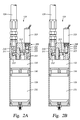
- FIGS. 2A and 2B are section views of the reservoir showing valves of a valve assembly in various positions during a compression stroke of the damper.
- FIGS. 3A and 3B are section views of the reservoir showing valves of a valve assembly in various positions during a rebound stroke of the damper.
- FIG. 4 is a section view of a damper in a compression stroke.
- FIG. 5 is a section view of the damper of FIG. 4 in a rebound stroke.
- FIG. 6 is a section view of a damper in a compression stroke.
- FIG. 7 is a section view of the damper of FIG. 6 in a rebound stroke.
- FIG. 8 is a schematic diagram showing a control arrangement for a remotely-operated valve.
- FIG. 9 is a schematic diagram showing another control arrangement for a remotely-operated valve.
- FIG. 1 is a section view of a suspension damper 100 .
- the damper 100 includes a cylinder portion 102 with a rod 107 and a piston 105 .
- fluid meters from one side of the piston 105 to the other side by passing through flow paths 110 , 112 formed in the piston 105 .
- shims 115 , 116 are used to partially obstruct flow paths 110 , 112 through the piston 105 in two directions.
- shims 115 are configured to meter rebound flow from the rebound portion 103 of the cylinder 102 to the compression portion 104 of the cylinder 102 (shown as arrow 110 ).
- Shims 116 are configured to meter compression flow from the compression portion 104 of the cylinder 102 to the rebound portion 103 (shown as arrow 112 ). In FIG.
- piston apertures may be included in planes other than those shown (e.g. other than apertures used by paths 110 and 112 ) and further that such apertures may, or may not, be subject to the shims 115 , 116 as shown (because for example, the shims 115 , 116 may be clover-shaped or have some other non-circular shape).
- the piston 105 is solid and all damping flow must traverse a flow bypass (e.g. annular space 150 between cylinder 102 and inner cylinder 151 ) and/or communicate with a reservoir.
- the damper 100 includes an annular bypass formed between a wall of cylinder portion 102 and an inner wall 151 having a slightly smaller diameter that the cylinder wall. In this manner an annular space 150 is provided between the walls.
- at least one port 153 on the compression side of the cylinder and another port 154 on the rebound side permit working fluid to pass between the compression and rebound sides without moving through the shimmed paths provided by the piston 105 .
- the bypass feature is utilized so long as the piston is between the two ports in either the compression or rebound strokes.
- the lower portion of the rod 107 is supplied with a bushing set 109 for connecting to a portion of a vehicle wheel suspension linkage.
- An upper portion of the cylinder 102 may be supplied with an eyelet 108 to be mounted to another portion of the vehicle, such as the frame, that moves independently of the first part.
- a spring member (not shown) is usually mounted to act between the same portions of the vehicle as the damper.
- the damping fluid slows the movement of the two portions of the vehicle relative to each other due, at least in part, to the incompressible fluid moving through the shimmed paths provided in the piston 105 and/or through the metered bypass.
- the rod 107 and piston 105 move out of the cylinder 102 (during extension or “rebound”) fluid meters again through shimmed paths and the flow rate and corresponding rebound rate is controlled, at least in part, by the shims 115 .
- a reservoir 125 is in fluid communication with the damper cylinder 102 for receiving and supplying damping fluid as the piston rod 107 moves in and out of the cylinder 102 , thereby variably displacing damping fluid.
- the reservoir 125 includes a cylinder portion 128 in fluid communication with the compression portion 104 of the damper cylinder 102 via fluid conduit 129 which houses a fluid path between the components.
- the reservoir 125 also includes a floating piston 130 with a volume of gas in a gas portion 131 on a backside (“blind end” side) of it, the gas being compressible as a fluid portion 132 of the reservoir cylinder 128 fills with damping fluid due to movement of the damper rod 107 into the damper cylinder 102 .
- the pressure of gas in portion 131 can be adjusted with compressed air introduced through gas valve 133 located at a lower end of the reservoir cylinder 128 .
- gas valve 133 located at a lower end of the reservoir cylinder 128 .
- Certain features of reservoir-type dampers are shown and described in U.S. Pat. No. 7,374,028, which is incorporated herein, in its entirety, by reference.
- the damper includes an in-line reservoir (e.g. floating piston and gas charge) rather than a remote reservoir as shown in FIG. 1 .
- the principles disclosed herein are equally applicable in either case.
- a reservoir valve assembly 200 includes two valves 210 , 220 , each of which permits or prevents fluid flow into the reservoir fluid portion 132 .
- the valves 210 , 220 are shown in more detail in FIGS. 2A , B and 3 A, B.
- FIGS. 2A and 2 B are section views of the reservoir 125 showing valves of the valve assembly 200 in various positions during a compression stroke of the damper 100 .
- FIGS. 3A and 3B are section views of the reservoir 125 showing valves of the valve assembly 200 in various positions during a rebound stroke of the damper 100 .
- valve 210 includes a pathway leading into the fluid portion 132 of the reservoir, the pathway including shims 212 functionally like those ( 115 , 116 ) used in damper piston 105 and designed to offer predetermined resistance to fluid flow passing into the reservoir 125 .
- Another set of shims 213 meter the flow of fluid out of the fluid portion 132 of the reservoir 125 during a rebound stroke of the damper ( FIGS. 3A , B).
- the flow of fluid into and through valve 210 in a compression stroke is shown by arrow 211 .
- the flow of fluid has un-seated shims 212 to permit the flow of fluid into the fluid portion 132 .
- valve assembly 200 is a remotely-operable valve 220 and includes a movable plunger 222 that is seatable on a seat 225 .
- the valve 220 is open with a fluid path therethrough shown by arrow 221 . While the Figure shows both valves open and fluid flow traveling through both, it will be understood that depending upon the design of the system, including the selection of shims, valve 210 might remain closed and fluid might flow only through open valve 220 (or vice versa).
- FIG. 2B remotely-operable valve 220 is shown in a closed position with the plunger 222 seated upon seat 225 .
- the valve 220 is shifted between an open and closed position by a solenoid 223 located above the valve and capable of receiving an electrical signal and causing the mechanical movement of the plunger 222 .
- the solenoid 223 operates in a manner that partially closes or partially opens the valve 220 , therefore permitting or restricting flow without completely opening or closing the valve (e.g. as in an infinitely variable throttle operating between absolute open and absolute closed positions).
- the solenoid-operated valve 220 is normally open (as shown in FIG. 2A ) with working or damping fluid permitted to flow through both valves 210 , 220 of reservoir valve assembly 200 .
- additional fluid may also bypass the shims of piston 105 due to the annular bypass 150 with its ports 153 , 154 ( FIG. 1 ).
- the foregoing configuration describes a “compliant” damping mode with reduced dampening which is suitable for “plush” shock absorption but which may also allow a so-equipped vehicle to pitch or roll during braking or cornering respectively. As such, compliant damping is sometimes preferable but there are times when a more rigid damping mode is appropriate.
- the normally-open solenoid valve 220 may be, at the user's discretion, partially or completely closed as it appears in FIG. 2B , to increase a damping rate of the damper 100 .
- Off-road use often requires a high degree of compliance to absorb shocks imparted by the widely varying terrain.
- FIGS. 3A and B show the operation of the damper 100 with working fluid traveling through the valves 210 , 220 of the assembly 200 in a rebound stroke.
- both valves are open to the flow of return fluid.
- a fluid path 216 is created through shims 213 of valve 210 and another path 217 through the solenoid-operated valve 220 which is shown in an open position, thereby reducing dampening effects and essentially permitting the shock absorber to retract faster than would otherwise be possible.
- FIG. 3B illustrates the same damper reservoir in a rebound stroke with the remotely-operable valve 220 in a closed position, thereby adding additional dampening to the rebounding piston 105 .
- One embodiment comprises a four wheeled vehicle having solenoid valve-equipped shock absorbers at each (of four) wheel.
- the solenoid valve 220 (which may be mechanically, pneumatically, or hydraulically operated instead of solenoid operated) of each of the front shock absorbers may be electrically connected with a linear, motion activated switch (such as that which operates an automotive brake light) that is activated in conjunction with the vehicle brake pedal.
- a linear, motion activated switch such as that which operates an automotive brake light
- the electric switch connects a power supply to the normally open solenoid in each of the front shocks, thereby closing the valve in those shocks.
- the front shocks become more rigid during hard braking.
- Other mechanisms may be used to trigger the shocks such as accelerometers (e.g., tri-axial) for sensing pitch and roll of the vehicle and activating, via a microprocessor, the appropriate solenoid valves for optimum vehicle control.
- a vehicle steering column includes right turn and left turn limit switches such that a hard turn in either direction activates (e.g. closes valve 220 ) the solenoid on the shocks opposite that direction (for example a hard right turn would cause more rigid shocks on the vehicle left side).
- accelerometers in conjunction with a microprocessor and a switched power supply may perform the solenoid activation function by sensing the actual g-force associated with the turn (or braking; or throttle acceleration for the rear shock activation) and triggering the appropriate solenoid(s) at a preset threshold g-force.
- a pressure intensifier damper arrangement may be located within the fluid path of the remotely-operable valves 220 such that the solenoid valve controls flow through that auxiliary damper which is then additive with the valve assembly 200 .
- the valve assembly 200 comprises a pressure intensifier (such as described in U.S. Pat. No. 7,374,028, which is incorporated, entirely, herein by reference).
- one or both of the valves 210 , 220 comprise standard shim-type dampers.
- one or both of the valves 210 , 220 include an adjustable needle for low speed bleed.
- a blow off e.g. checking poppet-type or shim is included in one of the flow paths associated with the valves 210 , 220 .
- FIG. 4 is a section view of a damper 100 in a compression stroke. Damping fluid is moved between compression chamber 363 and rebound chamber 365 via compression line 385 , reservoir 125 , and rebound line 386 .
- the damper 100 includes a main cylinder 102 having a piston 105 and shaft 107 .
- the piston is solid and fluid is moved in each direction in both the compression and rebound strokes of the damper.
- the piston could include shims to meter fluid between the compression 363 and rebound 365 sides of the cylinder 102 .
- the cylinder also includes a bypass structure formed by an annular area 300 between the outer wall 102 of the cylinder and an inner wall 101 .
- a port 154 leading from the annular area 300 to the rebound portion 365 of the chamber permits fluid flow into the rebound portion from the reservoir as will be explained.
- the reservoir 125 is equipped with a cylinder portion 128 housing a fluid portion 132 and a presurizable portion 131 separated by a floating piston 130 .
- a valve assembly 220 enclosed in the reservoir housing operates to meter fluid into and out of the reservoir 125 .
- damping fluid is moved by solid piston 105 out of compression chamber 363 along the compression feed flow path 370 and into fluid portion 132 of reservoir 125 via compression line 385 , an annulus 380 and a port 381 .
- the pressure in rebound chamber 365 decreases as solid piston 105 moves in compression.
- Damping fluid is correspondingly forced through the shims 115 of the valve assembly 200 and along the compression return flow path 371 to the rebound portion 365 (which includes travel through rebound line 386 , internal annulus 300 , and port 154 ).
- the volume of the shaft 107 incurring into the rebound/compression chamber 365 / 363 is accommodated by movement of floating piston 130 in the reservoir 125 and associated compression of pressurizable portion 131 .
- pressure in portion 131 increases, so does damping force of the shock absorber as increased pressure is communicated to the damping fluid by movement of the floating piston 130 (the damping fluid increases in pressure and affects change in the pressure of, in one embodiment, a gas in portion 131 ).
- Increased damping fluid pressure acts against the piston area of the solid piston 105 , thereby increasing the force on the shock absorber necessary cause compression of the shock absorber. In other words the shock absorber increasingly resists compression as it is compressed.
- FIG. 5 an illustration of a rebound stroke
- the shaft 107 is moving out of the chambers 365 , 363 as shown by directional arrow 118 .
- fluid flow directions are generally reversed from those shown in the compression stroke of FIG. 4 .
- fluid exits the reservoir 125 along a path 372 that utilizes annular space 380 and port 381 .
- the exiting fluid 372 returns to the main dampening cylinder 102 via annular area 300 and port 154 that leads to the rebound side 365 of the chamber.
- Rebound fluid enters the reservoir 125 via path 373 and passes through shims 116 in valve assembly 200 where it is metered.
- portion 131 of the chamber 128 comprises a compressible fluid such as a gas.
- an initial static pressure of the gas is set between 150 and 250 psi.
- the pressurizable portion 131 is in fluid communication with a connection member 330 and an adjustable pressure source (not shown but noted by “ 201 ”).
- the resistance of the shock absorber's increasing compression can be altered as desired by adjusting the pressure using the adjustable pressure source 201 . If the source pressure is decreased, the shock absorber will be relatively easier to compress and if the source pressure is increased, the shock absorber will be more resistant to compression.
- the source pressure can be increased for example, when a shock absorber-equipped vehicle is operated on relatively smooth surface such as a paved road and stiffness is more useful for good handling than compliance. Conversely, if a so-equipped vehicle is operated off-road, compliant travel may be more desirable and the source pressure would be correspondingly decreased. It is noteworthy that absent any adjustment of the source pressure, the increasing resistance of the damper based on compression of portion 131 is dependent primarily on the position of the shock in its travel (e.g. position dependent characteristic). As stated, the position/rigidity function associated with portion 131 and the damping fluid pressure can be selectively altered and tailored by adjusting a pressure of the adjustable pressure source 201 .
- the source pressure is adjustable by an operator of a vehicle.
- an on board source of compressed air can be used to add pressurized gas to portion 131 in varying amounts either by a switch in the vehicle compartment or as will be explained, in an automated fashion based upon vehicle or terrain conditions. Similarly, pressure can be removed from portion 131 as needed.
- FIGS. 6 and 7 illustrate a shock absorber that is similar to the shock absorber of FIGS. 4 and 5 in some respects and similar to the embodiments of FIGS. 1 through 3 in other respects.
- the valve assembly 200 includes a remotely-operable valve 220 in addition to shims 115 , 116 in order to permit additional and more responsive dampening control.
- the compression flow 370 travels out of chamber 363 through line 385 and into reservoir 125 .
- the compression flow path 370 is divided into two separate paths 370 A, 370 B, either or both of which can be used to control dampening.
- Path 370 A travels through shims 116 , like the shims of the other embodiments.
- Path 370 B travels through a remotely-operable valve 220 consisting of a plunger 222 and seat 225 .
- Valve 220 is shown in an open position permitting fluid flow therethrough and in doing so, providing a bypass around the dampening effects of the shims 116 .
- Return fluid travels along a path 371 from fluid portion 132 through port 381 , annular area 380 and on to the rebound portion 365 of main dampening chamber 102 , via return line 386 .
- FIG. 7 illustrates the operation of the damper of FIG. 6 in a rebound stroke.
- fluid from the rebound portion 365 of the main cylinder 102 utilizes port 154 and annular area 300 to exit cylinder along a path 373 .
- the rebound fluid enters the reservoir, it utilizes annular area 380 and port 381 to enter fluid portion 132 .
- the exiting fluid flow is divided into two paths 372 A and 372 B.
- Path 372 A takes the fluid through shims 115 and path 372 B takes part of the fluid through remotely-operable valve 220 .
- valve 220 in its open position as shown, reduces rebound dampening by providing a bypass around shims 115 .
- valve 220 is shown in FIGS. 6 and 7 in a fully open position, it will be understood that the valve could be closed or could assume any number of partially-open positions depending upon the requirements of a vehicle and/or terrain and an operator's needs.
- the valve assembly 200 is configured with a boost type position sensitive valve as shown and described in U.S. patent application Ser. No. 12/509,258 which is entirely incorporated herein by reference.
- the damping shims of the damping piston are selectively adjustable.
- the shims of the damping piston are fixed.
- the remotely-operable valve 220 may be solenoid operated (as illustrated in FIGS. 6 and 7 with solenoid 223 ) or hydraulically operated or pneumatically operated or operated by any other suitable motive mechanism.
- the valve may be operated remotely by a switch or potentiometer located in the cockpit of a vehicle or attached to appropriate operational parts of a vehicle for timely activation (e.g. brake pedal) or may be operated in response to input from a microprocessor (e.g. calculating desired settings based on vehicle acceleration sensor data) or any suitable combination of activation means.
- a controller for the adjustable pressure source (or for both the source and the valve) may be cockpit mounted and may be manually adjustable or microprocessor controlled or both or selectively either.
- Off-road use often requires a high degree of compliance to absorb shocks imparted by the widely varying terrain.
- One embodiment comprises a four wheeled vehicle having solenoid valve equipped shock absorbers at each (of four) wheel.
- the solenoid valve (which in one embodiment is cable operated instead of solenoid operated) of each of the front shock absorbers may be electrically connected with a linear switch (such as that which operates an automotive brake light) that is activated in conjunction with the vehicle brake pedal.
- a linear switch such as that which operates an automotive brake light
- the electric switch connects a power supply to the normally open solenoid in each of the front shocks thereby closing the paths 8 SA in those shocks.
- Other mechanisms may be used to trigger the shocks such as accelerometers (e.g. tri-axial) for sensing pitch and roll of the vehicle and activating, via a microprocessor, the appropriate solenoid valves for optimum vehicle control.
- a vehicle steering column includes right turn and left turn limit switches such that a hard turn in either direction activates (e.g. closes path 8 SA) the solenoid on the shocks opposite that direction (for example a hard right turn would cause more rigid shocks on the vehicle left side).
- accelerometers in conjunction with a microprocessor and a switched power supply may perform the solenoid activation function by sensing the actual g-force associated with the turn (or braking; or throttle acceleration for the rear shock activation) and triggering the appropriate solenoid(s) at a preset threshold g-force.
- a pressure intensifier damper arrangement may be located within the fluid path such that the solenoid-controlled valve controls flow through that auxiliary damper which is then additive with the damper mechanism of the damping piston.
- the damper mechanism of the damping piston comprises a pressure intensifier.
- one or both of the dampers comprise standard shim type dampers.
- one or both of the dampers include an adjustable needle for low speed bleed.
- a blow off e.g. checking poppet type or shim
- FIG. 8 is a schematic diagram showing a control arrangement 400 for a remotely-operated valve, like valve 220 described herein or in one embodiment, the pressure source 201 .
- a signal line 416 runs from a switch 415 to a solenoid 223 along an electrically conductive line 416 .
- the solenoid 223 converts electrical energy into mechanical movement (identified by item 405 ) and shifts a plunger of the valve 220 , thereby opening or closing the valve or causing the plunger to assume some predetermined position in-between.
- FIG. 8 is simplified and involves control of a single bypass valve 220 , it will be understood that any number of valves could be operated simultaneously or separately depending upon needs in a vehicular suspension system. Additional switches could permit individual operation of separate remotely-operable valves 220 .
- a remotely-operable valve 220 or a remotely operated pressure source 201 like the one described above is particularly useful with an on-/off-road vehicle.
- These vehicles can have as more than 20 ′′ of shock absorber travel to permit them to negotiate rough, uneven terrain at speed with usable shock absorbing function.
- compliant dampening is necessary as the vehicle relies on its long travel suspension when encountering often large off-road obstacles. Operating a vehicle with very compliant, long travel suspension on a smooth road at higher speeds can be problematic due to the springiness/sponginess of the suspension and corresponding vehicle handling problems associated with that (e.g. turning roll, braking pitch). Such compliance can cause reduced handling characteristics and even loss of control.
- dampening characteristics of a shock absorber can be completely changed from a compliantly dampened “springy” arrangement to a highly dampened and “stiffer” (or fully locked out) system ideal for higher speeds on a smooth road.
- closure of the valve 220 can result in substantial “lock out” of the suspension (the suspension is rendered essentially rigid except for the movement of fluid through shimmed valve 210 ).
- closure of the valve 220 results in a stiffer but still functional compression damper.
- FIG. 9 shows a schematic diagram of a remote control system 500 based upon any or all of vehicle speed, damper rod speed, and damper rod position.
- One embodiment of the arrangement of FIG. 9 is designed to automatically increase dampening in a shock absorber in the event a damper rod reaches a certain velocity in its travel towards the bottom end of a damper at a predetermined speed of the vehicle.
- the system 500 adds dampening (and control) in the event of rapid operation (e.g.
- the system 500 adds dampening (e.g. closes or throttles down the bypass) in the event that the rod velocity in compression is relatively low but the rod progresses past a certain point in the travel.
- dampening e.g. closes or throttles down the bypass
- Such configuration aids in stabilizing the vehicle against excessive low-rate suspension movement events such as cornering roll, braking and acceleration yaw and pitch and “g-out.”
- FIG. 9 illustrates, for example, a system 500 including three variables: rod speed, rod position and vehicle speed. Any or all of the variables shown may be considered by logic unit 502 in controlling the solenoids of valves 220 or control of a remotely operated pressure source. Any other suitable vehicle operation variable may be used in addition to or in lieu of the variables 515 , 505 , 510 such as, for example, piston rod compression strain, eyelet strain, vehicle mounted accelerometer (or tilt/inclinometer) data or any other suitable vehicle or component performance data.
- piston 105 's position within cylinder 102 is determined using an accelerometer to sense modal resonance of cylinder 102 .
- a suitable proximity sensor or linear coil transducer or other electro-magnetic transducer is incorporated in the dampening cylinder 102 to provide a sensor to monitor the position and/or speed of the piston 105 (and suitable magnetic tag) with respect to the cylinder 102 .
- the magnetic transducer includes a waveguide and a magnet, such as a doughnut (toroidal) magnet that is joined to the cylinder and oriented such that the magnetic field generated by the magnet passes through the piston rod 107 and the waveguide.
- Electric pulses are applied to the waveguide from a pulse generator that provides a stream of electric pulses, each of which is also provided to a signal processing circuit for timing purposes.
- a magnetic field is formed surrounding the waveguide. Interaction of this field with the magnetic field from the magnet causes a torsional strain wave pulse to be launched in the waveguide in both directions away from the magnet.
- a coil assembly and sensing tape is joined to the waveguide.
- the strain wave causes a dynamic effect in the permeability of the sensing tape which is biased with a permanent magnetic field by the magnet.
- the dynamic effect in the magnetic field of the coil assembly due to the strain wave pulse results in an output signal from the coil assembly that is provided to the signal processing circuit along signal lines.
- the signal processing circuit can calculate a distance of the magnet from the coil assembly or the relative velocity between the waveguide and the magnet.
- the signal processing circuit provides an output signal, either digital or analog, proportional to the calculated distance and/or velocity.
- a separate wheel speed transducer for sensing the rotational speed of a wheel about an axle includes housing fixed to the axle and containing therein, for example, two permanent magnets.
- the magnets are arranged such that an elongated pole piece commonly abuts first surfaces of each of the magnets, such surfaces being of like polarity.
- Two inductive coils having flux-conductive cores axially passing therethrough abut each of the magnets on second surfaces thereof, the second surfaces of the magnets again being of like polarity with respect to each other and of opposite polarity with respect to the first surfaces.
- Wheel speed transducers are described in U.S. Pat. No. 3,986,118 which is incorporated herein by reference in its entirety.
- the logic unit 502 with user-definable settings receives inputs from the rod speed 510 and location 505 transducers as well as the wheel speed transducer 515 .
- the logic unit 502 is user-programmable and depending on the needs of the operator, the unit records the variables and then if certain criteria are met, the logic circuit sends its own signal to the bypass to either close or open (or optionally throttle) the remotely-operable valve 220 . Thereafter, the condition of the bypass valve is relayed back to the logic unit 502 .
- the logic shown in FIG. 9 assumes a single damper but the logic circuit is usable with any number of dampers or groups of dampers. For instance, the dampers on one side of the vehicle can be acted upon while the vehicles other dampers remain unaffected.
- valve 220 (with or without valve 210 in valve assembly 200 ) or the remote operation of pressure source 201 can be used in a variety of ways with many different driving and road variables.
- the valve 220 is controlled based upon vehicle speed in conjunction with the angular location of the vehicle's steering wheel. In this manner, by sensing the steering wheel turn severity (angle of rotation), additional dampening can be applied to one damper or one set of dampers on one side of the vehicle (suitable for example to mitigate cornering roll) in the event of a sharp turn at a relatively high speed.
- a transducer such as an accelerometer measures other aspects of the vehicle's suspension system, like axle force and/or moments applied to various parts of the vehicle, like steering tie rods, and directs change to the bypass valve positioning in response thereto.
- the bypass can be controlled at least in part by a pressure transducer measuring pressure in a vehicle tire and adding dampening characteristics to some or all of the wheels in the event of, for example, an increased or decreased pressure reading.
- the damper bypass or bypasses are controlled in response to braking pressure (as measured, for example, by a brake pedal sensor or brake fluid pressure sensor or accelerometer).
- a parameter might include a gyroscopic mechanism that monitors vehicle trajectory and identifies a “spin-out” or other loss of control condition and adds and/or reduces dampening to some or all of the vehicle's dampers in the event of a loss of control to help the operator of the vehicle to regain control.
Landscapes
- Engineering & Computer Science (AREA)
- General Engineering & Computer Science (AREA)
- Mechanical Engineering (AREA)
- Vehicle Body Suspensions (AREA)
Abstract
Description
Claims (16)
Priority Applications (39)
| Application Number | Priority Date | Filing Date | Title |
|---|---|---|---|
| US13/189,216 US9239090B2 (en) | 2009-01-07 | 2011-07-22 | Suspension damper with remotely-operable valve |
| US13/750,336 US9556925B2 (en) | 2009-01-07 | 2013-01-25 | Suspension damper with by-pass valves |
| US13/843,704 US9033122B2 (en) | 2009-01-07 | 2013-03-15 | Method and apparatus for an adjustable damper |
| US13/934,067 US10060499B2 (en) | 2009-01-07 | 2013-07-02 | Method and apparatus for an adjustable damper |
| US14/251,446 US10047817B2 (en) | 2009-01-07 | 2014-04-11 | Method and apparatus for an adjustable damper |
| US14/466,831 US9452654B2 (en) | 2009-01-07 | 2014-08-22 | Method and apparatus for an adjustable damper |
| US14/690,267 US9663181B2 (en) | 2009-01-07 | 2015-04-17 | Method and apparatus for an adjustable damper |
| US14/965,761 US20160153516A1 (en) | 2009-01-07 | 2015-12-10 | Suspension damper with remotely-operable valve |
| US15/275,078 US10040329B2 (en) | 2009-01-07 | 2016-09-23 | Method and apparatus for an adjustable damper |
| US15/418,322 US10556477B2 (en) | 2009-01-07 | 2017-01-27 | Suspension damper with by-pass valves |
| US15/599,469 US10160511B2 (en) | 2009-01-07 | 2017-05-19 | Method and apparatus for an adjustable damper |
| US16/042,563 US10814689B2 (en) | 2009-01-07 | 2018-07-23 | Method and apparatus for an adjustable damper |
| US16/045,403 US11168758B2 (en) | 2009-01-07 | 2018-07-25 | Method and apparatus for an adjustable damper |
| US16/046,497 US10670106B2 (en) | 2009-01-07 | 2018-07-26 | Method and apparatus for an adjustable damper |
| US16/051,346 US10807433B2 (en) | 2009-01-07 | 2018-07-31 | Method and apparatus for an adjustable damper |
| US16/051,023 US10336148B2 (en) | 2009-01-07 | 2018-07-31 | Method and apparatus for an adjustable damper |
| US16/051,156 US10800220B2 (en) | 2009-01-07 | 2018-07-31 | Method and apparatus for an adjustable damper |
| US16/051,302 US10821795B2 (en) | 2009-01-07 | 2018-07-31 | Method and apparatus for an adjustable damper |
| US16/051,245 US10336149B2 (en) | 2009-01-07 | 2018-07-31 | Method and apparatus for an adjustable damper |
| US16/175,656 US11306798B2 (en) | 2008-05-09 | 2018-10-30 | Position sensitive suspension damping with an active valve |
| US16/203,203 US12122205B2 (en) | 2009-01-07 | 2018-11-28 | Active valve for an internal bypass |
| US16/224,516 US10723409B2 (en) | 2009-01-07 | 2018-12-18 | Method and apparatus for an adjustable damper |
| US16/424,334 US11660924B2 (en) | 2009-01-07 | 2019-05-28 | Method and apparatus for an adjustable damper |
| US16/425,240 US11173765B2 (en) | 2009-01-07 | 2019-05-29 | Method and apparatus for an adjustable damper |
| US16/888,720 US11549565B2 (en) | 2009-01-07 | 2020-05-30 | Method and apparatus for an adjustable damper |
| US16/938,484 US11299233B2 (en) | 2009-01-07 | 2020-07-24 | Method and apparatus for an adjustable damper |
| US17/068,569 US12583276B2 (en) | 2020-10-12 | Method and apparatus for an adjustable damper | |
| US17/073,730 US11794543B2 (en) | 2009-01-07 | 2020-10-19 | Method and apparatus for an adjustable damper |
| US17/078,858 US12134293B2 (en) | 2009-01-07 | 2020-10-23 | Method and apparatus for an adjustable damper |
| US17/083,837 US12257871B2 (en) | 2009-01-07 | 2020-10-29 | Method and apparatus for an adjustable damper |
| US17/519,897 US12091122B2 (en) | 2009-01-07 | 2021-11-05 | Method and apparatus for an adjustable damper |
| US17/526,425 US11890908B2 (en) | 2009-01-07 | 2021-11-15 | Method and apparatus for an adjustable damper |
| US17/716,919 US11866120B2 (en) | 2009-01-07 | 2022-04-08 | Method and apparatus for an adjustable damper |
| US17/722,211 US12504053B2 (en) | 2008-05-09 | 2022-04-15 | Position sensitive suspension damping with an active valve |
| US17/722,240 US12504054B2 (en) | 2008-05-09 | 2022-04-15 | Position sensitive suspension damping with an active valve |
| US17/956,632 US20230131078A1 (en) | 2009-01-07 | 2022-09-29 | Method and apparatus for an adjustable damper |
| US18/407,270 US12371122B2 (en) | 2009-01-07 | 2024-01-08 | Method and apparatus for an adjustable damper |
| US18/740,129 US12377699B2 (en) | 2009-01-07 | 2024-06-11 | Method and apparatus for an adjustable damper |
| US19/288,180 US20250353343A1 (en) | 2009-01-07 | 2025-08-01 | Method and apparatus for an adjustable damper |
Applications Claiming Priority (9)
| Application Number | Priority Date | Filing Date | Title |
|---|---|---|---|
| US14315209P | 2009-01-07 | 2009-01-07 | |
| US12/684,072 US20100170760A1 (en) | 2009-01-07 | 2010-01-07 | Remotely Operated Bypass for a Suspension Damper |
| US29682610P | 2010-01-20 | 2010-01-20 | |
| US36112710P | 2010-07-02 | 2010-07-02 | |
| US36687110P | 2010-07-22 | 2010-07-22 | |
| US38190610P | 2010-09-10 | 2010-09-10 | |
| US13/010,697 US8857580B2 (en) | 2009-01-07 | 2011-01-20 | Remotely operated bypass for a suspension damper |
| US13/175,244 US8627932B2 (en) | 2009-01-07 | 2011-07-01 | Bypass for a suspension damper |
| US13/189,216 US9239090B2 (en) | 2009-01-07 | 2011-07-22 | Suspension damper with remotely-operable valve |
Related Parent Applications (4)
| Application Number | Title | Priority Date | Filing Date |
|---|---|---|---|
| US12/684,072 Continuation-In-Part US20100170760A1 (en) | 2008-05-09 | 2010-01-07 | Remotely Operated Bypass for a Suspension Damper |
| US13/010,697 Continuation-In-Part US8857580B2 (en) | 2008-05-09 | 2011-01-20 | Remotely operated bypass for a suspension damper |
| US13/175,244 Continuation-In-Part US8627932B2 (en) | 2008-05-09 | 2011-07-01 | Bypass for a suspension damper |
| US13/189,216 Continuation-In-Part US9239090B2 (en) | 2008-05-09 | 2011-07-22 | Suspension damper with remotely-operable valve |
Related Child Applications (7)
| Application Number | Title | Priority Date | Filing Date |
|---|---|---|---|
| US12/684,072 Continuation-In-Part US20100170760A1 (en) | 2008-05-09 | 2010-01-07 | Remotely Operated Bypass for a Suspension Damper |
| US13/189,216 Continuation-In-Part US9239090B2 (en) | 2008-05-09 | 2011-07-22 | Suspension damper with remotely-operable valve |
| US13/485,401 Continuation-In-Part US20120305350A1 (en) | 2008-05-09 | 2012-05-31 | Methods and apparatus for position sensitive suspension damping |
| US13/843,704 Continuation-In-Part US9033122B2 (en) | 2008-05-09 | 2013-03-15 | Method and apparatus for an adjustable damper |
| US13/934,067 Continuation-In-Part US10060499B2 (en) | 2008-05-09 | 2013-07-02 | Method and apparatus for an adjustable damper |
| US14/251,446 Continuation-In-Part US10047817B2 (en) | 2008-05-09 | 2014-04-11 | Method and apparatus for an adjustable damper |
| US14/965,761 Continuation US20160153516A1 (en) | 2009-01-07 | 2015-12-10 | Suspension damper with remotely-operable valve |
Publications (2)
| Publication Number | Publication Date |
|---|---|
| US20120018263A1 US20120018263A1 (en) | 2012-01-26 |
| US9239090B2 true US9239090B2 (en) | 2016-01-19 |
Family
ID=45492667
Family Applications (2)
| Application Number | Title | Priority Date | Filing Date |
|---|---|---|---|
| US13/189,216 Active 2031-05-27 US9239090B2 (en) | 2008-05-09 | 2011-07-22 | Suspension damper with remotely-operable valve |
| US14/965,761 Pending US20160153516A1 (en) | 2009-01-07 | 2015-12-10 | Suspension damper with remotely-operable valve |
Family Applications After (1)
| Application Number | Title | Priority Date | Filing Date |
|---|---|---|---|
| US14/965,761 Pending US20160153516A1 (en) | 2009-01-07 | 2015-12-10 | Suspension damper with remotely-operable valve |
Country Status (1)
| Country | Link |
|---|---|
| US (2) | US9239090B2 (en) |
Cited By (83)
| Publication number | Priority date | Publication date | Assignee | Title |
|---|---|---|---|---|
| US9353818B2 (en) | 2009-01-07 | 2016-05-31 | Fox Factory, Inc. | Remotely operated bypass for a suspension damper |
| US20160159184A1 (en) * | 2014-12-03 | 2016-06-09 | Icon Vehicle Dynamics, LLC | Shock absorbers |
| US9452654B2 (en) | 2009-01-07 | 2016-09-27 | Fox Factory, Inc. | Method and apparatus for an adjustable damper |
| US9616728B2 (en) | 2009-01-07 | 2017-04-11 | Fox Factory, Inc. | Bypass for a suspension damper |
| US9663181B2 (en) | 2009-01-07 | 2017-05-30 | Fox Factory, Inc. | Method and apparatus for an adjustable damper |
| US9784333B2 (en) | 2009-01-07 | 2017-10-10 | Fox Factory, Inc. | Compression isolator for a suspension damper |
| US20180010666A1 (en) * | 2010-01-20 | 2018-01-11 | Fox Factory, Inc. | Remotely operated bypass for a suspension damper |
| US10036443B2 (en) | 2009-03-19 | 2018-07-31 | Fox Factory, Inc. | Methods and apparatus for suspension adjustment |
| US10047817B2 (en) | 2009-01-07 | 2018-08-14 | Fox Factory, Inc. | Method and apparatus for an adjustable damper |
| US10060499B2 (en) | 2009-01-07 | 2018-08-28 | Fox Factory, Inc. | Method and apparatus for an adjustable damper |
| US10072724B2 (en) | 2008-08-25 | 2018-09-11 | Fox Factory, Inc. | Methods and apparatus for suspension lock out and signal generation |
| US10086670B2 (en) | 2009-03-19 | 2018-10-02 | Fox Factory, Inc. | Methods and apparatus for suspension set up |
| US10214071B1 (en) | 2016-05-28 | 2019-02-26 | PAL Suspension LLC | Vehicle suspension system with multi-stage hydraulic cylinder assemblies and external spring packs |
| EP3461661A2 (en) | 2017-09-29 | 2019-04-03 | Fox Factory, Inc. | Modular electronic damping control |
| EP3461663A1 (en) | 2017-09-29 | 2019-04-03 | Fox Factory, Inc. | Electronically controlled sway bar damping link |
| US10330171B2 (en) | 2012-05-10 | 2019-06-25 | Fox Factory, Inc. | Method and apparatus for an adjustable damper |
| US10406883B2 (en) | 2009-10-13 | 2019-09-10 | Fox Factory, Inc. | Methods and apparatus for controlling a fluid damper |
| US10443671B2 (en) | 2009-01-07 | 2019-10-15 | Fox Factory, Inc. | Remotely operated bypass for a suspension damper |
| US10556477B2 (en) | 2009-01-07 | 2020-02-11 | Fox Factory, Inc. | Suspension damper with by-pass valves |
| US10591015B2 (en) | 2009-03-19 | 2020-03-17 | Fox Factory, Inc. | Methods and apparatus for suspension adjustment |
| EP3660349A1 (en) | 2018-11-28 | 2020-06-03 | Fox Factory, Inc. | Active valve for an internal bypass |
| US10677309B2 (en) | 2011-05-31 | 2020-06-09 | Fox Factory, Inc. | Methods and apparatus for position sensitive suspension damping |
| EP3663605A1 (en) | 2018-10-30 | 2020-06-10 | Fox Factory, Inc. | Position sensitive suspension damping with an active valve |
| US10731724B2 (en) | 2009-10-13 | 2020-08-04 | Fox Factory, Inc. | Suspension system |
| US10737546B2 (en) | 2016-04-08 | 2020-08-11 | Fox Factory, Inc. | Electronic compression and rebound control |
| US10737545B1 (en) | 2019-12-19 | 2020-08-11 | PAL Suspension LLC | Vehicle suspension system with multi-stage hydraulic cylinder assemblies and external spring packs |
| US10821795B2 (en) | 2009-01-07 | 2020-11-03 | Fox Factory, Inc. | Method and apparatus for an adjustable damper |
| WO2021041950A1 (en) | 2019-08-29 | 2021-03-04 | Fox Factory, Inc. | Smart device application with customizable tunes for active valve control |
| US11021204B2 (en) | 2008-11-25 | 2021-06-01 | Fox Factory, Inc. | Seat post |
| EP3828016A1 (en) | 2019-11-26 | 2021-06-02 | Fox Factory, Inc. | Selecting different suspension tunes via a manually operated switch |
| US20210260951A1 (en) * | 2012-02-03 | 2021-08-26 | Fox Factory, Inc. | Suspension with hydraulic preload adjust |
| EP3875800A1 (en) | 2020-02-27 | 2021-09-08 | Fox Factory, Inc. | A shock assembly |
| EP3875801A1 (en) | 2020-02-27 | 2021-09-08 | Fox Factory, Inc. | A shock assembly and method |
| EP3888957A1 (en) | 2020-04-02 | 2021-10-06 | Fox Factory, Inc. | System for vehicle suspension management |
| EP3895966A1 (en) | 2020-03-30 | 2021-10-20 | Fox Factory, Inc. | Integrated active valve assembly |
| EP3926204A1 (en) | 2020-06-05 | 2021-12-22 | Fox Factory, Inc. | An electronic external bypass |
| EP3939813A1 (en) | 2020-07-15 | 2022-01-19 | Fox Factory, Inc. | Active valve customizable tune application |
| US20220041028A1 (en) * | 2018-10-30 | 2022-02-10 | Air Lift Company | Method of operating vehicle control system |
| US11279199B2 (en) | 2012-01-25 | 2022-03-22 | Fox Factory, Inc. | Suspension damper with by-pass valves |
| US11299233B2 (en) | 2009-01-07 | 2022-04-12 | Fox Factory, Inc. | Method and apparatus for an adjustable damper |
| US11306798B2 (en) | 2008-05-09 | 2022-04-19 | Fox Factory, Inc. | Position sensitive suspension damping with an active valve |
| US20220118814A1 (en) * | 2019-08-01 | 2022-04-21 | Audi Ag | Spring damper apparatus for a vehicle, in particular for a motor vehicle, and vehicle having at least one such spring damper apparatus |
| EP3995717A1 (en) | 2020-11-04 | 2022-05-11 | Fox Factory, Inc. | Self-contained airshock assembly |
| EP4015264A1 (en) | 2020-12-17 | 2022-06-22 | Fox Factory, Inc. | Sway bar system |
| EP4021029A1 (en) | 2020-12-28 | 2022-06-29 | Fox Factory, Inc. | Wireless switch for an active component |
| EP4019304A1 (en) | 2020-12-28 | 2022-06-29 | Fox Factory, Inc. | Wireless active suspension system |
| EP4036436A1 (en) | 2021-02-01 | 2022-08-03 | Fox Factory, Inc. | Three-port adjuster |
| EP4040011A1 (en) | 2021-01-28 | 2022-08-10 | Fox Factory, Inc. | A damper with an annular base valve flow system |
| US11413924B2 (en) | 2009-03-19 | 2022-08-16 | Fox Factory, Inc. | Methods and apparatus for selective spring pre-load adjustment |
| EP4046833A1 (en) | 2021-02-23 | 2022-08-24 | Fox Factory, Inc. | Vehicle and bump sensor |
| US11448283B2 (en) | 2019-04-29 | 2022-09-20 | Fox Factory, Inc. | Main piston boost valve in a vehicle damper |
| US11459050B2 (en) | 2019-09-03 | 2022-10-04 | Fox Factory, Inc. | Connected component platform |
| US20220339987A1 (en) * | 2013-03-14 | 2022-10-27 | Oshkosh Defense, Llc | Load dependent damper for a vehicle suspension system |
| US20220403909A1 (en) * | 2021-06-16 | 2022-12-22 | Fox Factory, Inc. | Adjustable shock assembly |
| EP4125068A1 (en) | 2021-07-29 | 2023-02-01 | Fox Factory, Inc. | Connected component platform |
| US11602971B2 (en) | 2019-02-22 | 2023-03-14 | Fox Factory, Inc. | Mechanical bypass of electronic valve body |
| EP4147890A1 (en) | 2021-09-14 | 2023-03-15 | Fox Factory, Inc. | Vehicle and wireless active suspension system |
| EP4197830A1 (en) | 2021-12-20 | 2023-06-21 | Fox Factory, Inc. | Electronically controlled sway bar damper link |
| EP4230448A1 (en) | 2022-02-04 | 2023-08-23 | Fox Factory, Inc. | Limited range sharing of localized suspension setup information |
| EP4253106A1 (en) | 2022-02-23 | 2023-10-04 | Fox Factory, Inc. | Hydraulic cross-linked suspension |
| EP4269137A1 (en) | 2022-04-26 | 2023-11-01 | Fox Factory, Inc. | System and method |
| US11833876B2 (en) | 2020-07-15 | 2023-12-05 | Fox Factory, Inc. | Rough road detection |
| EP4290090A1 (en) | 2022-06-10 | 2023-12-13 | Fox Factory, Inc. | Integrated bearing hardware for shock assembly |
| US11866110B2 (en) | 2010-07-02 | 2024-01-09 | Fox Factory, Inc. | Lever assembly for positive lock adjustable seat post |
| US11946526B2 (en) | 2020-11-26 | 2024-04-02 | Bombardier Recreational Products Inc. | Shock absorber for a vehicle |
| US20240300276A1 (en) * | 2023-03-10 | 2024-09-12 | Arctic Cat Inc. | Off-Road Vehicle having an Actively Adjustable Suspension |
| US12110943B2 (en) | 2019-10-15 | 2024-10-08 | Fox Factory, Inc. | Modular active valve system having a reduced footprint for use in a smaller shock platform |
| US12112579B2 (en) | 2019-09-03 | 2024-10-08 | Fox Factory, Inc. | Connected component platform |
| US12122205B2 (en) | 2009-01-07 | 2024-10-22 | Fox Factory, Inc. | Active valve for an internal bypass |
| US12138977B2 (en) | 2020-11-19 | 2024-11-12 | Fox Factory, Inc. | Energy harvesting switch |
| US12234879B2 (en) | 2020-04-09 | 2025-02-25 | Fox Factory, Inc. | User accessible shock travel spacer |
| US12253139B2 (en) * | 2019-09-19 | 2025-03-18 | Fox Factory, Inc. | Dual live valve shock having main damper and base valve actively controlled |
| US12270062B2 (en) | 2017-09-08 | 2025-04-08 | Fox Factory, Inc. | Electronically controlled sway bar damping link |
| US12311720B2 (en) | 2022-02-23 | 2025-05-27 | Fox Factory, Inc. | Hydraulic cross-linked suspension |
| US12330734B2 (en) | 2022-04-15 | 2025-06-17 | Fox Factory, Inc. | Active suspension and body wearable device integration |
| US12409697B2 (en) | 2022-05-06 | 2025-09-09 | Fox Factory, Inc. | Self-pumping spring preload system |
| US12442429B2 (en) | 2021-05-12 | 2025-10-14 | Vorsprung Technologies, Ltd. | High dynamic range suspension apparatus with selective fluid pressure communication |
| US12491961B2 (en) | 2008-11-25 | 2025-12-09 | Fox Factory, Inc. | Seat post |
| US12496867B2 (en) | 2020-02-27 | 2025-12-16 | Fox Factory, Inc. | Hydraulically-adjustable preload and/or cross-over |
| US12502923B2 (en) | 2022-02-23 | 2025-12-23 | Fox Factory, Inc. | Hydraulic cross-linked suspension |
| US12522042B1 (en) * | 2024-10-24 | 2026-01-13 | Fox Factory, Inc. | Linked gas chambers for e-sway disconnect |
| US12545072B2 (en) | 2019-10-22 | 2026-02-10 | Fox Factory, Inc. | Hydraulic anti-roll bar link |
| US12583276B2 (en) | 2020-10-12 | 2026-03-24 | Fox Factory, Inc. | Method and apparatus for an adjustable damper |
Families Citing this family (36)
| Publication number | Priority date | Publication date | Assignee | Title |
|---|---|---|---|---|
| SE533996C2 (en) * | 2009-04-23 | 2011-03-22 | Oehlins Racing Ab | Pressure regulator in a shock absorber valve |
| US8616351B2 (en) | 2009-10-06 | 2013-12-31 | Tenneco Automotive Operating Company Inc. | Damper with digital valve |
| GB0919682D0 (en) * | 2009-11-11 | 2009-12-23 | Hi Lex Cable System Company Ltd | Damper |
| US8763770B2 (en) * | 2011-03-03 | 2014-07-01 | Fox Factory, Inc. | Cooler for a suspension damper |
| EP2577027A2 (en) | 2010-06-03 | 2013-04-10 | Polaris Industries Inc. | Electronic throttle control |
| EP2858840A4 (en) * | 2012-06-08 | 2016-01-13 | Msi Defense Solutions Llc | ELECTRONICALLY ADJUSTABLE SHOCK ABSORBER AND SYSTEM |
| US9205717B2 (en) | 2012-11-07 | 2015-12-08 | Polaris Industries Inc. | Vehicle having suspension with continuous damping control |
| US9884533B2 (en) | 2013-02-28 | 2018-02-06 | Tenneco Automotive Operating Company Inc. | Autonomous control damper |
| US9217483B2 (en) | 2013-02-28 | 2015-12-22 | Tenneco Automotive Operating Company Inc. | Valve switching controls for adjustable damper |
| WO2014134500A1 (en) | 2013-02-28 | 2014-09-04 | Tenneco Automotive Operating Company Inc. | Damper with integrated electronics |
| US9879748B2 (en) | 2013-03-15 | 2018-01-30 | Tenneco Automotive Operating Company Inc. | Two position valve with face seal and pressure relief port |
| US9163691B2 (en) | 2013-03-15 | 2015-10-20 | Tenneco Automotive Operating Company Inc. | Rod guide arrangement for electronically controlled valve applications |
| US9879746B2 (en) | 2013-03-15 | 2018-01-30 | Tenneco Automotive Operating Company Inc. | Rod guide system and method with multiple solenoid valve cartridges and multiple pressure regulated valve assemblies |
| CN105308351B (en) | 2013-03-15 | 2017-08-15 | 坦尼科汽车操作有限公司 | Bar guide assembly with multi-piece type valve member |
| AU2014273843B2 (en) | 2013-05-30 | 2017-11-09 | Arb Corporation Limited | A shock absorber |
| JP6062113B2 (en) | 2013-07-31 | 2017-01-18 | ベイジンウェスト・インダストリーズ・カンパニー・リミテッドBeijingwest Industries Co., Ltd. | Hydraulic suspension damper |
| US9796232B2 (en) * | 2014-04-11 | 2017-10-24 | Fox Factory, Inc. | Twin tube damper with remote gas reservoir |
| WO2016069405A2 (en) | 2014-10-31 | 2016-05-06 | Polaris Industries Inc. | System and method for controlling a vehicle |
| US9672967B1 (en) * | 2016-03-23 | 2017-06-06 | Honda Motor Co., Ltd. | Electromagnetic cart lock |
| EP3488121B1 (en) | 2016-07-20 | 2022-03-02 | Elka Suspension Inc. | Position-relative damper assist system |
| US11110913B2 (en) | 2016-11-18 | 2021-09-07 | Polaris Industries Inc. | Vehicle having adjustable suspension |
| US10588233B2 (en) | 2017-06-06 | 2020-03-10 | Tenneco Automotive Operating Company Inc. | Damper with printed circuit board carrier |
| US10479160B2 (en) | 2017-06-06 | 2019-11-19 | Tenneco Automotive Operating Company Inc. | Damper with printed circuit board carrier |
| US10406884B2 (en) | 2017-06-09 | 2019-09-10 | Polaris Industries Inc. | Adjustable vehicle suspension system |
| US11009093B2 (en) * | 2017-10-16 | 2021-05-18 | Suspension Direct, Inc. | Electronically adjustable shock absorber |
| EP3489049B1 (en) * | 2017-11-28 | 2024-09-18 | Volvo Car Corporation | Electronic high impact damper (ehid) |
| DE112019005068B4 (en) * | 2018-10-12 | 2023-01-05 | Hitachi Astemo, Ltd. | suspension control device |
| US10987987B2 (en) | 2018-11-21 | 2021-04-27 | Polaris Industries Inc. | Vehicle having adjustable compression and rebound damping |
| US11434968B2 (en) * | 2019-02-25 | 2022-09-06 | Mark Brendan Newhan | Vehicle shock absorber |
| US11505024B2 (en) | 2019-10-08 | 2022-11-22 | Off-Road Research LLC | Electronically controlled external damper reservoir |
| US11618296B2 (en) * | 2020-01-22 | 2023-04-04 | Shock Therapy Suspension, Inc. | Shock stiffener system |
| CN115666975A (en) | 2020-05-20 | 2023-01-31 | 北极星工业有限公司 | Systems and methods for adjustable suspensions for off-road recreational vehicles |
| US11904648B2 (en) | 2020-07-17 | 2024-02-20 | Polaris Industries Inc. | Adjustable suspensions and vehicle operation for off-road recreational vehicles |
| EP4147889A1 (en) * | 2021-09-08 | 2023-03-15 | Volvo Car Corporation | Damper system and method for changing a ground clearance of a vehicle |
| CN116379091A (en) * | 2023-04-19 | 2023-07-04 | 厦门腾威胜检测科技有限公司 | An oil-air damping system with adjustable body attitude and stiffness |
| US12491746B1 (en) | 2024-10-25 | 2025-12-09 | Shock Therapy Suspension, Inc. | Shock stiffener system |
Citations (37)
| Publication number | Priority date | Publication date | Assignee | Title |
|---|---|---|---|---|
| US2492331A (en) | 1947-03-27 | 1949-12-27 | Spring Russell Mason | Shock absorber valve regulator |
| US2991804A (en) | 1959-05-27 | 1961-07-11 | Gen Motors Corp | Air suspension and control apparatus therefor |
| US4334711A (en) * | 1980-10-27 | 1982-06-15 | American Standard Inc. | System for automatically delaying application of a snow brake for a railway vehicle |
| US4491207A (en) * | 1983-07-15 | 1985-01-01 | Lord Corporation | Fluid control means for vehicle suspension system |
| JPH01106721A (en) | 1987-10-20 | 1989-04-24 | Tokico Ltd | Shock absorber |
| DE3738048A1 (en) | 1987-11-09 | 1989-05-18 | Rexroth Mannesmann Gmbh | Device for damping the self-movements of the masses of a linear two-mass oscillator |
| US4936424A (en) * | 1989-05-09 | 1990-06-26 | Costa Vince F | Hydraulic shock absorber with pressure sensitive external valving |
| US4949989A (en) | 1988-04-19 | 1990-08-21 | Atsugi Motor Parts Co., Ltd. | Automotive suspension system with variable suspension characteristics and variable damping force shock absorber therefor |
| JPH04203540A (en) | 1990-11-29 | 1992-07-24 | Mazda Motor Corp | Damping force adjusting type hydraulic buffer |
| US5163742A (en) * | 1990-03-08 | 1992-11-17 | Mercedes-Benz Ag | Method of distributing brake pressure to the axles of a motor vehicle with an abs pressure-medium brake |
| US5203584A (en) | 1990-04-17 | 1993-04-20 | Mazada Motor Corporation | Suspension system for a vehicle |
| JPH05149364A (en) | 1991-11-30 | 1993-06-15 | Tokico Ltd | Damping force adjustable hydraulic shock absorber |
| US5598337A (en) | 1992-09-30 | 1997-01-28 | Mazda Motor Corporation | Suspension apparatus with driving state feedback for vehicles |
| US5884921A (en) | 1996-08-29 | 1999-03-23 | Toyota Jidosha Kabushiki Kaisha | Electric control apparatus for damper device in suspension system of automotive vehicle |
| US6035979A (en) | 1996-06-21 | 2000-03-14 | Fichtel & Sachs Ag | Vibration damper and a vibration damper with a damping valve having an adjustable damping force |
| US6058340A (en) | 1993-12-28 | 2000-05-02 | Tokico Ltd. | Suspension control apparatus |
| US6092011A (en) * | 1997-04-08 | 2000-07-18 | Unisia Jecs Corporation | Apparatus and method for controlling damping force characteristic of vehicular shock absorber |
| US6213263B1 (en) * | 1996-07-24 | 2001-04-10 | Donerre Amortisseur | Oil damper system |
| US6254067B1 (en) * | 1999-08-02 | 2001-07-03 | Giant Manufacturing Co., Ltd. | Fluid regulating device for use with a hydraulic cylinder to obtain a variable shock absorbing effect |
| US20010017334A1 (en) * | 2000-02-29 | 2001-08-30 | Vincent Alan Henry | Vibration damping apparatus |
| US6296092B1 (en) | 1998-10-28 | 2001-10-02 | Fox Factory, Inc. | Position-sensitive shock absorber |
| EP1241087A1 (en) | 2001-03-13 | 2002-09-18 | Shimano Inc. | Bicycle suspension |
| US6474753B1 (en) * | 1996-08-21 | 2002-11-05 | Continental Teves Ag & Co., Ohg | Automatically actuated braking system |
| US20030160369A1 (en) | 2002-01-11 | 2003-08-28 | Laplante John A. | Semi-active shock absorber control system |
| US20040222056A1 (en) | 2001-08-30 | 2004-11-11 | Fox Robert C. | Inertia valve shock absorber |
| US20050110229A1 (en) | 2003-10-16 | 2005-05-26 | Ryoji Kimura | Vehicle height adjusting apparatus |
| US6991076B2 (en) | 1999-04-06 | 2006-01-31 | Specialized Bicycle Components, Inc. | Bicycle damping enhancement system |
| US20060065496A1 (en) | 2001-08-30 | 2006-03-30 | Fox Factory, Inc. | Inertia valve shock absorber |
| US20060124414A1 (en) * | 2004-12-09 | 2006-06-15 | Nobumichi Hanawa | Front fork |
| US20060289258A1 (en) | 2003-07-08 | 2006-12-28 | Fox Robert C | Damper with pressure-sensitive compression damping |
| US20070008096A1 (en) | 2005-05-14 | 2007-01-11 | Tracy Randy L | Reversibly mountable acceleration/de-acceleration warning light |
| US7299112B2 (en) | 2004-11-03 | 2007-11-20 | Activeshock, Inc. | Electrically controlled pressure relief valve and system and method for controlling same |
| JP2007302211A (en) | 2006-05-15 | 2007-11-22 | Toyota Motor Corp | Suspension system |
| US20080059025A1 (en) | 2006-08-29 | 2008-03-06 | Honda Motor Co., Ltd. | Vehicle state estimation system |
| US20090277736A1 (en) | 2008-05-09 | 2009-11-12 | Specialized Bicycle Components, Inc. | Bicycle damper |
| US20100010709A1 (en) | 2008-01-24 | 2010-01-14 | Cannondale Bicycle Corporation | Bicycle distributed computing arrangement and method of operation |
| US20120253599A1 (en) | 2011-03-30 | 2012-10-04 | Shimano Inc. | Bicycle suspension control apparatus |
Family Cites Families (18)
| Publication number | Priority date | Publication date | Assignee | Title |
|---|---|---|---|---|
| DE6751082U (en) * | 1967-06-22 | 1969-01-23 | Moulton Development Ltd | CHASSIS |
| US4121610A (en) * | 1976-02-02 | 1978-10-24 | Ambac Industries Incorporated | Electrically operated proportional flow control hydraulic valve and manually operable remote control device therefor |
| US4159106A (en) * | 1977-11-10 | 1979-06-26 | Nyman Bengt E | Vehicular suspension unit |
| FR2529002A2 (en) * | 1979-10-10 | 1983-12-23 | Laporte Yves | Autonomous multi-facet road sign with remote control - uses photo-voltaic cell array to provide energy for rechargeable battery driving motor which can act directly or pressurise fluid |
| US4333668A (en) * | 1979-12-17 | 1982-06-08 | The Bendix Corporation | Electronic adaptive ride control system |
| US4729459A (en) * | 1984-10-01 | 1988-03-08 | Nippon Soken, Inc. | Adjustable damping force type shock absorber |
| US4958706A (en) * | 1988-11-14 | 1990-09-25 | Richardson Donald G | Adjustable shock absorbers |
| SE462726B (en) * | 1989-06-02 | 1990-08-20 | Stromsholmens Mek Verkstad | DEVICE BY A GAS SPRING |
| DE3931857A1 (en) * | 1989-09-23 | 1991-04-04 | Bosch Gmbh Robert | DAMPING SYSTEM |
| DE19615737A1 (en) * | 1996-04-20 | 1997-10-16 | Daimler Benz Ag | Active suspension system |
| US5971116A (en) * | 1997-03-13 | 1999-10-26 | Cannondale Corporation | Electronic suspension system for a wheeled vehicle |
| US6322468B1 (en) * | 1999-11-17 | 2001-11-27 | Borgwarner Inc. | Pressure relief valve and dual path vent disc for hydraulic tensioner |
| JP4547793B2 (en) * | 2000-11-17 | 2010-09-22 | 株式会社アドヴィックス | Vehicle motion control device |
| US20050173849A1 (en) * | 2004-02-10 | 2005-08-11 | Bart Vandewal | Electronically controlled frequency dependent damping |
| US7401680B2 (en) * | 2004-12-23 | 2008-07-22 | Phonak Ag | Hearing protection earplug and use of the same |
| US20060163551A1 (en) * | 2005-01-27 | 2006-07-27 | Duane Coenen | Hydraulic vehicle jack system |
| KR101068988B1 (en) * | 2005-03-29 | 2011-09-30 | 주식회사 만도 | Air suspension and electronically controlled suspension device |
| US7963377B2 (en) * | 2005-04-06 | 2011-06-21 | GM Global Technology Operations LLC | Dual stage dampers for vehicles suspensions |
-
2011
- 2011-07-22 US US13/189,216 patent/US9239090B2/en active Active
-
2015
- 2015-12-10 US US14/965,761 patent/US20160153516A1/en active Pending
Patent Citations (41)
| Publication number | Priority date | Publication date | Assignee | Title |
|---|---|---|---|---|
| US2492331A (en) | 1947-03-27 | 1949-12-27 | Spring Russell Mason | Shock absorber valve regulator |
| US2991804A (en) | 1959-05-27 | 1961-07-11 | Gen Motors Corp | Air suspension and control apparatus therefor |
| US4334711A (en) * | 1980-10-27 | 1982-06-15 | American Standard Inc. | System for automatically delaying application of a snow brake for a railway vehicle |
| US4491207A (en) * | 1983-07-15 | 1985-01-01 | Lord Corporation | Fluid control means for vehicle suspension system |
| JPH01106721A (en) | 1987-10-20 | 1989-04-24 | Tokico Ltd | Shock absorber |
| DE3738048A1 (en) | 1987-11-09 | 1989-05-18 | Rexroth Mannesmann Gmbh | Device for damping the self-movements of the masses of a linear two-mass oscillator |
| US4949989A (en) | 1988-04-19 | 1990-08-21 | Atsugi Motor Parts Co., Ltd. | Automotive suspension system with variable suspension characteristics and variable damping force shock absorber therefor |
| US4936424A (en) * | 1989-05-09 | 1990-06-26 | Costa Vince F | Hydraulic shock absorber with pressure sensitive external valving |
| US5163742A (en) * | 1990-03-08 | 1992-11-17 | Mercedes-Benz Ag | Method of distributing brake pressure to the axles of a motor vehicle with an abs pressure-medium brake |
| US5203584A (en) | 1990-04-17 | 1993-04-20 | Mazada Motor Corporation | Suspension system for a vehicle |
| JPH04203540A (en) | 1990-11-29 | 1992-07-24 | Mazda Motor Corp | Damping force adjusting type hydraulic buffer |
| JPH05149364A (en) | 1991-11-30 | 1993-06-15 | Tokico Ltd | Damping force adjustable hydraulic shock absorber |
| US5598337A (en) | 1992-09-30 | 1997-01-28 | Mazda Motor Corporation | Suspension apparatus with driving state feedback for vehicles |
| US6058340A (en) | 1993-12-28 | 2000-05-02 | Tokico Ltd. | Suspension control apparatus |
| US6035979A (en) | 1996-06-21 | 2000-03-14 | Fichtel & Sachs Ag | Vibration damper and a vibration damper with a damping valve having an adjustable damping force |
| US6213263B1 (en) * | 1996-07-24 | 2001-04-10 | Donerre Amortisseur | Oil damper system |
| US6474753B1 (en) * | 1996-08-21 | 2002-11-05 | Continental Teves Ag & Co., Ohg | Automatically actuated braking system |
| US5884921A (en) | 1996-08-29 | 1999-03-23 | Toyota Jidosha Kabushiki Kaisha | Electric control apparatus for damper device in suspension system of automotive vehicle |
| US6092011A (en) * | 1997-04-08 | 2000-07-18 | Unisia Jecs Corporation | Apparatus and method for controlling damping force characteristic of vehicular shock absorber |
| US6296092B1 (en) | 1998-10-28 | 2001-10-02 | Fox Factory, Inc. | Position-sensitive shock absorber |
| US6415895B2 (en) | 1998-10-28 | 2002-07-09 | Fox Factory, Inc. | Position-sensitive shock absorber |
| US6991076B2 (en) | 1999-04-06 | 2006-01-31 | Specialized Bicycle Components, Inc. | Bicycle damping enhancement system |
| US20080093820A1 (en) | 1999-04-06 | 2008-04-24 | Specialized Bicycle Components, Inc. | Bicycle damping enhancement system |
| US7270221B2 (en) * | 1999-04-06 | 2007-09-18 | Specialized Bicycle Components, Inc. | Bicycle damping enhancement system |
| US6254067B1 (en) * | 1999-08-02 | 2001-07-03 | Giant Manufacturing Co., Ltd. | Fluid regulating device for use with a hydraulic cylinder to obtain a variable shock absorbing effect |
| US20010017334A1 (en) * | 2000-02-29 | 2001-08-30 | Vincent Alan Henry | Vibration damping apparatus |
| EP1241087A1 (en) | 2001-03-13 | 2002-09-18 | Shimano Inc. | Bicycle suspension |
| US7128192B2 (en) | 2001-08-30 | 2006-10-31 | Fox Factory, Inc. | Inertia valve shock absorber |
| US20060065496A1 (en) | 2001-08-30 | 2006-03-30 | Fox Factory, Inc. | Inertia valve shock absorber |
| US20040222056A1 (en) | 2001-08-30 | 2004-11-11 | Fox Robert C. | Inertia valve shock absorber |
| US20030160369A1 (en) | 2002-01-11 | 2003-08-28 | Laplante John A. | Semi-active shock absorber control system |
| US20060289258A1 (en) | 2003-07-08 | 2006-12-28 | Fox Robert C | Damper with pressure-sensitive compression damping |
| US20050110229A1 (en) | 2003-10-16 | 2005-05-26 | Ryoji Kimura | Vehicle height adjusting apparatus |
| US7299112B2 (en) | 2004-11-03 | 2007-11-20 | Activeshock, Inc. | Electrically controlled pressure relief valve and system and method for controlling same |
| US20060124414A1 (en) * | 2004-12-09 | 2006-06-15 | Nobumichi Hanawa | Front fork |
| US20070008096A1 (en) | 2005-05-14 | 2007-01-11 | Tracy Randy L | Reversibly mountable acceleration/de-acceleration warning light |
| JP2007302211A (en) | 2006-05-15 | 2007-11-22 | Toyota Motor Corp | Suspension system |
| US20080059025A1 (en) | 2006-08-29 | 2008-03-06 | Honda Motor Co., Ltd. | Vehicle state estimation system |
| US20100010709A1 (en) | 2008-01-24 | 2010-01-14 | Cannondale Bicycle Corporation | Bicycle distributed computing arrangement and method of operation |
| US20090277736A1 (en) | 2008-05-09 | 2009-11-12 | Specialized Bicycle Components, Inc. | Bicycle damper |
| US20120253599A1 (en) | 2011-03-30 | 2012-10-04 | Shimano Inc. | Bicycle suspension control apparatus |
Cited By (183)
| Publication number | Priority date | Publication date | Assignee | Title |
|---|---|---|---|---|
| US11306798B2 (en) | 2008-05-09 | 2022-04-19 | Fox Factory, Inc. | Position sensitive suspension damping with an active valve |
| US12504054B2 (en) | 2008-05-09 | 2025-12-23 | Fox Factory, Inc. | Position sensitive suspension damping with an active valve |
| US12504053B2 (en) | 2008-05-09 | 2025-12-23 | Fox Factory, Inc. | Position sensitive suspension damping with an active valve |
| US10072724B2 (en) | 2008-08-25 | 2018-09-11 | Fox Factory, Inc. | Methods and apparatus for suspension lock out and signal generation |
| US11162555B2 (en) | 2008-08-25 | 2021-11-02 | Fox Factory, Inc. | Methods and apparatus for suspension lock out and signal generation |
| US10550909B2 (en) | 2008-08-25 | 2020-02-04 | Fox Factory, Inc. | Methods and apparatus for suspension lock out and signal generation |
| US11897571B2 (en) | 2008-11-25 | 2024-02-13 | Fox Factory, Inc. | Seat post |
| US11021204B2 (en) | 2008-11-25 | 2021-06-01 | Fox Factory, Inc. | Seat post |
| US12491961B2 (en) | 2008-11-25 | 2025-12-09 | Fox Factory, Inc. | Seat post |
| US10821795B2 (en) | 2009-01-07 | 2020-11-03 | Fox Factory, Inc. | Method and apparatus for an adjustable damper |
| US11866120B2 (en) | 2009-01-07 | 2024-01-09 | Fox Factory, Inc. | Method and apparatus for an adjustable damper |
| US10047817B2 (en) | 2009-01-07 | 2018-08-14 | Fox Factory, Inc. | Method and apparatus for an adjustable damper |
| US10060499B2 (en) | 2009-01-07 | 2018-08-28 | Fox Factory, Inc. | Method and apparatus for an adjustable damper |
| US11549565B2 (en) | 2009-01-07 | 2023-01-10 | Fox Factory, Inc. | Method and apparatus for an adjustable damper |
| US9353818B2 (en) | 2009-01-07 | 2016-05-31 | Fox Factory, Inc. | Remotely operated bypass for a suspension damper |
| US10094443B2 (en) | 2009-01-07 | 2018-10-09 | Fox Factory, Inc. | Bypass for a suspension damper |
| US10160511B2 (en) | 2009-01-07 | 2018-12-25 | Fox Factory, Inc. | Method and apparatus for an adjustable damper |
| US11660924B2 (en) | 2009-01-07 | 2023-05-30 | Fox Factory, Inc. | Method and apparatus for an adjustable damper |
| US11519477B2 (en) | 2009-01-07 | 2022-12-06 | Fox Factory, Inc. | Compression isolator for a suspension damper |
| US11499601B2 (en) | 2009-01-07 | 2022-11-15 | Fox Factory, Inc. | Remotely operated bypass for a suspension damper |
| US11794543B2 (en) | 2009-01-07 | 2023-10-24 | Fox Factory, Inc. | Method and apparatus for an adjustable damper |
| US11408482B2 (en) | 2009-01-07 | 2022-08-09 | Fox Factory, Inc. | Bypass for a suspension damper |
| US10336148B2 (en) | 2009-01-07 | 2019-07-02 | Fox Factory, Inc. | Method and apparatus for an adjustable damper |
| US10336149B2 (en) | 2009-01-07 | 2019-07-02 | Fox Factory, Inc. | Method and apparatus for an adjustable damper |
| US10400847B2 (en) | 2009-01-07 | 2019-09-03 | Fox Factory, Inc. | Compression isolator for a suspension damper |
| US9616728B2 (en) | 2009-01-07 | 2017-04-11 | Fox Factory, Inc. | Bypass for a suspension damper |
| US10415662B2 (en) | 2009-01-07 | 2019-09-17 | Fox Factory, Inc. | Remotely operated bypass for a suspension damper |
| US10443671B2 (en) | 2009-01-07 | 2019-10-15 | Fox Factory, Inc. | Remotely operated bypass for a suspension damper |
| US9784333B2 (en) | 2009-01-07 | 2017-10-10 | Fox Factory, Inc. | Compression isolator for a suspension damper |
| US10556477B2 (en) | 2009-01-07 | 2020-02-11 | Fox Factory, Inc. | Suspension damper with by-pass valves |
| US11890908B2 (en) | 2009-01-07 | 2024-02-06 | Fox Factory, Inc. | Method and apparatus for an adjustable damper |
| US9452654B2 (en) | 2009-01-07 | 2016-09-27 | Fox Factory, Inc. | Method and apparatus for an adjustable damper |
| US10670106B2 (en) | 2009-01-07 | 2020-06-02 | Fox Factory, Inc. | Method and apparatus for an adjustable damper |
| US9663181B2 (en) | 2009-01-07 | 2017-05-30 | Fox Factory, Inc. | Method and apparatus for an adjustable damper |
| US11299233B2 (en) | 2009-01-07 | 2022-04-12 | Fox Factory, Inc. | Method and apparatus for an adjustable damper |
| US12377699B2 (en) | 2009-01-07 | 2025-08-05 | Fox Factory, Inc. | Method and apparatus for an adjustable damper |
| US11976706B2 (en) | 2009-01-07 | 2024-05-07 | Fox Factory, Inc. | Remotely operated bypass for a suspension damper |
| US10723409B2 (en) | 2009-01-07 | 2020-07-28 | Fox Factory, Inc. | Method and apparatus for an adjustable damper |
| US11173765B2 (en) | 2009-01-07 | 2021-11-16 | Fox Factory, Inc. | Method and apparatus for an adjustable damper |
| US11168758B2 (en) | 2009-01-07 | 2021-11-09 | Fox Factory, Inc. | Method and apparatus for an adjustable damper |
| US12371122B2 (en) | 2009-01-07 | 2025-07-29 | Fox Factory, Inc. | Method and apparatus for an adjustable damper |
| US12044286B2 (en) * | 2009-01-07 | 2024-07-23 | Fox Factory, Inc. | Compression isolator for a suspension damper |
| US12091122B2 (en) | 2009-01-07 | 2024-09-17 | Fox Factory, Inc. | Method and apparatus for an adjustable damper |
| US10800220B2 (en) | 2009-01-07 | 2020-10-13 | Fox Factory, Inc. | Method and apparatus for an adjustable damper |
| US10807433B2 (en) | 2009-01-07 | 2020-10-20 | Fox Factory, Inc. | Method and apparatus for an adjustable damper |
| US10814689B2 (en) | 2009-01-07 | 2020-10-27 | Fox Factory, Inc. | Method and apparatus for an adjustable damper |
| US20230098340A1 (en) * | 2009-01-07 | 2023-03-30 | Fox Factory, Inc. | Compression isolator for a suspension damper |
| US12122205B2 (en) | 2009-01-07 | 2024-10-22 | Fox Factory, Inc. | Active valve for an internal bypass |
| US12134293B2 (en) | 2009-01-07 | 2024-11-05 | Fox Factory, Inc. | Method and apparatus for an adjustable damper |
| US12257871B2 (en) | 2009-01-07 | 2025-03-25 | Fox Factory, Inc. | Method and apparatus for an adjustable damper |
| US10781879B2 (en) | 2009-01-07 | 2020-09-22 | Fox Factory, Inc. | Bypass for a suspension damper |
| US10040329B2 (en) | 2009-01-07 | 2018-08-07 | Fox Factory, Inc. | Method and apparatus for an adjustable damper |
| US11920655B2 (en) | 2009-03-19 | 2024-03-05 | Fox Factory, Inc. | Methods and apparatus for suspension adjustment |
| US11619278B2 (en) | 2009-03-19 | 2023-04-04 | Fox Factory, Inc. | Methods and apparatus for suspension adjustment |
| US11655873B2 (en) | 2009-03-19 | 2023-05-23 | Fox Factory, Inc. | Methods and apparatus for suspension adjustment |
| US10086670B2 (en) | 2009-03-19 | 2018-10-02 | Fox Factory, Inc. | Methods and apparatus for suspension set up |
| US10036443B2 (en) | 2009-03-19 | 2018-07-31 | Fox Factory, Inc. | Methods and apparatus for suspension adjustment |
| US12103349B2 (en) | 2009-03-19 | 2024-10-01 | Fox Factory, Inc. | Methods and apparatus for selective spring pre-load adjustment |
| US11413924B2 (en) | 2009-03-19 | 2022-08-16 | Fox Factory, Inc. | Methods and apparatus for selective spring pre-load adjustment |
| US10591015B2 (en) | 2009-03-19 | 2020-03-17 | Fox Factory, Inc. | Methods and apparatus for suspension adjustment |
| US12163569B2 (en) | 2009-03-19 | 2024-12-10 | Fox Factory, Inc. | Methods and apparatus for suspension adjustment |
| US10731724B2 (en) | 2009-10-13 | 2020-08-04 | Fox Factory, Inc. | Suspension system |
| US10406883B2 (en) | 2009-10-13 | 2019-09-10 | Fox Factory, Inc. | Methods and apparatus for controlling a fluid damper |
| US12005755B2 (en) | 2009-10-13 | 2024-06-11 | Fox Factory, Inc. | Methods and apparatus for controlling a fluid damper |
| US11279198B2 (en) | 2009-10-13 | 2022-03-22 | Fox Factory, Inc. | Methods and apparatus for controlling a fluid damper |
| US11859690B2 (en) | 2009-10-13 | 2024-01-02 | Fox Factory, Inc. | Suspension system |
| US11708878B2 (en) | 2010-01-20 | 2023-07-25 | Fox Factory, Inc. | Remotely operated bypass for a suspension damper |
| US10697514B2 (en) * | 2010-01-20 | 2020-06-30 | Fox Factory, Inc. | Remotely operated bypass for a suspension damper |
| US20180010666A1 (en) * | 2010-01-20 | 2018-01-11 | Fox Factory, Inc. | Remotely operated bypass for a suspension damper |
| US11866110B2 (en) | 2010-07-02 | 2024-01-09 | Fox Factory, Inc. | Lever assembly for positive lock adjustable seat post |
| US11796028B2 (en) | 2011-05-31 | 2023-10-24 | Fox Factory, Inc. | Methods and apparatus for position sensitive suspension damping |
| US10677309B2 (en) | 2011-05-31 | 2020-06-09 | Fox Factory, Inc. | Methods and apparatus for position sensitive suspension damping |
| US12539729B2 (en) | 2011-09-12 | 2026-02-03 | Fox Factory, Inc. | Methods and apparatus for suspension set up |
| US10759247B2 (en) | 2011-09-12 | 2020-09-01 | Fox Factory, Inc. | Methods and apparatus for suspension set up |
| US11958328B2 (en) | 2011-09-12 | 2024-04-16 | Fox Factory, Inc. | Methods and apparatus for suspension set up |
| US11279199B2 (en) | 2012-01-25 | 2022-03-22 | Fox Factory, Inc. | Suspension damper with by-pass valves |
| US11760150B2 (en) | 2012-01-25 | 2023-09-19 | Fox Factory, Inc. | Suspension damper with by-pass valves |
| US12145415B2 (en) * | 2012-02-03 | 2024-11-19 | Fox Factory, Inc. | Suspension with hydraulic preload adjust |
| US20210260951A1 (en) * | 2012-02-03 | 2021-08-26 | Fox Factory, Inc. | Suspension with hydraulic preload adjust |
| US10330171B2 (en) | 2012-05-10 | 2019-06-25 | Fox Factory, Inc. | Method and apparatus for an adjustable damper |
| US12038062B2 (en) | 2012-05-10 | 2024-07-16 | Fox Factory, Inc. | Method and apparatus for an adjustable damper |
| US10859133B2 (en) | 2012-05-10 | 2020-12-08 | Fox Factory, Inc. | Method and apparatus for an adjustable damper |
| US11629774B2 (en) | 2012-05-10 | 2023-04-18 | Fox Factory, Inc. | Method and apparatus for an adjustable damper |
| US20220339987A1 (en) * | 2013-03-14 | 2022-10-27 | Oshkosh Defense, Llc | Load dependent damper for a vehicle suspension system |
| US12246572B1 (en) * | 2013-03-14 | 2025-03-11 | Oshkosh Defense, Llc | Load dependent damper for a vehicle suspension system |
| US11685221B2 (en) * | 2013-03-14 | 2023-06-27 | Oshkosh Defense, Llc | Load dependent damper for a vehicle suspension system |
| US20160159184A1 (en) * | 2014-12-03 | 2016-06-09 | Icon Vehicle Dynamics, LLC | Shock absorbers |
| US10035396B2 (en) | 2014-12-03 | 2018-07-31 | Icon Vehicle Dynamics Llc | Shock absorbers |
| US10625555B2 (en) | 2014-12-03 | 2020-04-21 | Icon Vehicle Dynamics Llc | Shock absorbers |
| US9610819B2 (en) * | 2014-12-03 | 2017-04-04 | Icon Vehicle Dynamics Llc | Shock absorbers |
| US11472252B2 (en) | 2016-04-08 | 2022-10-18 | Fox Factory, Inc. | Electronic compression and rebound control |
| US10737546B2 (en) | 2016-04-08 | 2020-08-11 | Fox Factory, Inc. | Electronic compression and rebound control |
| US10214071B1 (en) | 2016-05-28 | 2019-02-26 | PAL Suspension LLC | Vehicle suspension system with multi-stage hydraulic cylinder assemblies and external spring packs |
| US12270062B2 (en) | 2017-09-08 | 2025-04-08 | Fox Factory, Inc. | Electronically controlled sway bar damping link |
| EP4112339A1 (en) | 2017-09-29 | 2023-01-04 | Fox Factory, Inc. | Electronically controlled sway bar damping link |
| US10981429B2 (en) | 2017-09-29 | 2021-04-20 | Fox Factory, Inc. | Electronically controlled sway bar damping link |
| US20210229519A1 (en) * | 2017-09-29 | 2021-07-29 | Fox Factory, Inc. | Electronically controlled sway bar damping link |
| EP3865323A1 (en) | 2017-09-29 | 2021-08-18 | Fox Factory, Inc. | Modular electronic damping control |
| US20190100071A1 (en) * | 2017-09-29 | 2019-04-04 | Fox Factory, Inc. | Electronically controlled sway bar damping link |
| US12036835B2 (en) | 2017-09-29 | 2024-07-16 | Fox Factory, Inc. | Modular electronic damping control |
| EP3461661A2 (en) | 2017-09-29 | 2019-04-03 | Fox Factory, Inc. | Modular electronic damping control |
| EP3461663A1 (en) | 2017-09-29 | 2019-04-03 | Fox Factory, Inc. | Electronically controlled sway bar damping link |
| US11697317B2 (en) | 2017-09-29 | 2023-07-11 | Fox Factory, Inc. | Modular electronic damping control |
| US11926189B2 (en) * | 2017-09-29 | 2024-03-12 | Fox Factory, Inc. | Electronically controlled sway bar damping link |
| US10933710B2 (en) | 2017-09-29 | 2021-03-02 | Fox Factory, Inc. | Modular electronic damping control |
| EP4219978A2 (en) | 2018-10-30 | 2023-08-02 | Fox Factory, Inc. | Position sensitive suspension damping with an active valve |
| EP3663605A1 (en) | 2018-10-30 | 2020-06-10 | Fox Factory, Inc. | Position sensitive suspension damping with an active valve |
| US20220041028A1 (en) * | 2018-10-30 | 2022-02-10 | Air Lift Company | Method of operating vehicle control system |
| EP3660349A1 (en) | 2018-11-28 | 2020-06-03 | Fox Factory, Inc. | Active valve for an internal bypass |
| US11884122B2 (en) | 2019-02-22 | 2024-01-30 | Fox Factory, Inc. | Mechanical bypass of a valve body |
| US11602971B2 (en) | 2019-02-22 | 2023-03-14 | Fox Factory, Inc. | Mechanical bypass of electronic valve body |
| US11448283B2 (en) | 2019-04-29 | 2022-09-20 | Fox Factory, Inc. | Main piston boost valve in a vehicle damper |
| US11796030B2 (en) | 2019-04-29 | 2023-10-24 | Fox Factory, Inc. | Main piston boost valve in a vehicle damper |
| US20220118814A1 (en) * | 2019-08-01 | 2022-04-21 | Audi Ag | Spring damper apparatus for a vehicle, in particular for a motor vehicle, and vehicle having at least one such spring damper apparatus |
| US11833877B2 (en) * | 2019-08-01 | 2023-12-05 | Audi Ag | Spring damper apparatus for a vehicle, in particular for a motor vehicle, and vehicle having at least one such spring damper apparatus |
| US12151771B2 (en) | 2019-08-29 | 2024-11-26 | Fox Factory, Inc. | Smart device application with customizable tunes for active valve control |
| WO2021041950A1 (en) | 2019-08-29 | 2021-03-04 | Fox Factory, Inc. | Smart device application with customizable tunes for active valve control |
| US11713093B2 (en) | 2019-08-29 | 2023-08-01 | Fox Factory, Inc. | Smart device application with customizable tunes for active valve control |
| US12497125B2 (en) | 2019-08-29 | 2025-12-16 | Fox Factory, Inc. | Smart device application with customizable tunes for active valve control |
| US11459050B2 (en) | 2019-09-03 | 2022-10-04 | Fox Factory, Inc. | Connected component platform |
| US12112579B2 (en) | 2019-09-03 | 2024-10-08 | Fox Factory, Inc. | Connected component platform |
| US12195130B2 (en) | 2019-09-03 | 2025-01-14 | Fox Factory, Inc. | Connected component platform |
| US12253139B2 (en) * | 2019-09-19 | 2025-03-18 | Fox Factory, Inc. | Dual live valve shock having main damper and base valve actively controlled |
| US12110943B2 (en) | 2019-10-15 | 2024-10-08 | Fox Factory, Inc. | Modular active valve system having a reduced footprint for use in a smaller shock platform |
| US12545072B2 (en) | 2019-10-22 | 2026-02-10 | Fox Factory, Inc. | Hydraulic anti-roll bar link |
| US11975792B2 (en) | 2019-11-26 | 2024-05-07 | Fox Factory, Inc. | Selecting different suspension tunes via a manually operated switch |
| US12447789B1 (en) | 2019-11-26 | 2025-10-21 | Fox Factory, Inc. | Selecting different suspension tunes via a manually operated switch |
| EP3828016A1 (en) | 2019-11-26 | 2021-06-02 | Fox Factory, Inc. | Selecting different suspension tunes via a manually operated switch |
| US10737545B1 (en) | 2019-12-19 | 2020-08-11 | PAL Suspension LLC | Vehicle suspension system with multi-stage hydraulic cylinder assemblies and external spring packs |
| EP3875800A1 (en) | 2020-02-27 | 2021-09-08 | Fox Factory, Inc. | A shock assembly |
| EP3875801A1 (en) | 2020-02-27 | 2021-09-08 | Fox Factory, Inc. | A shock assembly and method |
| US11840120B2 (en) | 2020-02-27 | 2023-12-12 | Fox Factory, Inc. | IFP shock with automatically adjustable ride height |
| US12325276B2 (en) | 2020-02-27 | 2025-06-10 | Fox Factory, Inc. | IFP shock with automatically adjustable ride height |
| US12496867B2 (en) | 2020-02-27 | 2025-12-16 | Fox Factory, Inc. | Hydraulically-adjustable preload and/or cross-over |
| US12227048B2 (en) | 2020-02-27 | 2025-02-18 | Fox Factory, Inc. | Shock assembly with automatically adjustable ride height |
| US11718137B2 (en) | 2020-02-27 | 2023-08-08 | Fox Factory, Inc. | Shock assembly with automatically adjustable ride height |
| EP3895966A1 (en) | 2020-03-30 | 2021-10-20 | Fox Factory, Inc. | Integrated active valve assembly |
| EP3888957A1 (en) | 2020-04-02 | 2021-10-06 | Fox Factory, Inc. | System for vehicle suspension management |
| US12234879B2 (en) | 2020-04-09 | 2025-02-25 | Fox Factory, Inc. | User accessible shock travel spacer |
| US12435772B2 (en) | 2020-06-05 | 2025-10-07 | Fox Factory, Inc. | Electronic external bypass |
| US11927242B2 (en) | 2020-06-05 | 2024-03-12 | Fox Factory, Inc. | Electronic external bypass |
| EP3926204A1 (en) | 2020-06-05 | 2021-12-22 | Fox Factory, Inc. | An electronic external bypass |
| US12311717B2 (en) | 2020-07-15 | 2025-05-27 | Fox Factory, Inc. | Rough road detection |
| EP3939812A1 (en) | 2020-07-15 | 2022-01-19 | Fox Factory, Inc. | Rough road detection |
| US11833876B2 (en) | 2020-07-15 | 2023-12-05 | Fox Factory, Inc. | Rough road detection |
| EP3939813A1 (en) | 2020-07-15 | 2022-01-19 | Fox Factory, Inc. | Active valve customizable tune application |
| US12583276B2 (en) | 2020-10-12 | 2026-03-24 | Fox Factory, Inc. | Method and apparatus for an adjustable damper |
| EP3995717A1 (en) | 2020-11-04 | 2022-05-11 | Fox Factory, Inc. | Self-contained airshock assembly |
| US12479254B2 (en) | 2020-11-04 | 2025-11-25 | Fox Factory, Inc. | Self-contained airshock assembly |
| US12138977B2 (en) | 2020-11-19 | 2024-11-12 | Fox Factory, Inc. | Energy harvesting switch |
| US11946526B2 (en) | 2020-11-26 | 2024-04-02 | Bombardier Recreational Products Inc. | Shock absorber for a vehicle |
| EP4015264A1 (en) | 2020-12-17 | 2022-06-22 | Fox Factory, Inc. | Sway bar system |
| US12263711B2 (en) | 2020-12-17 | 2025-04-01 | Fox Factory, Inc. | Automated control system for an electronically controlled sway bar link |
| US11634003B2 (en) | 2020-12-17 | 2023-04-25 | Fox Factory, Inc. | Automated control system for an electronically controlled sway bar link |
| EP4019304A1 (en) | 2020-12-28 | 2022-06-29 | Fox Factory, Inc. | Wireless active suspension system |
| EP4021029A1 (en) | 2020-12-28 | 2022-06-29 | Fox Factory, Inc. | Wireless switch for an active component |
| EP4588771A2 (en) | 2020-12-28 | 2025-07-23 | Fox Factory, Inc. | Wireless active suspension system |
| US12428098B2 (en) | 2020-12-28 | 2025-09-30 | Fox Factory, Inc. | Wireless active suspension system |
| US12065214B2 (en) | 2020-12-28 | 2024-08-20 | Fox Factory, Inc. | Wireless active suspension system |
| EP4040011A1 (en) | 2021-01-28 | 2022-08-10 | Fox Factory, Inc. | A damper with an annular base valve flow system |
| EP4036436A1 (en) | 2021-02-01 | 2022-08-03 | Fox Factory, Inc. | Three-port adjuster |
| US12330459B2 (en) | 2021-02-01 | 2025-06-17 | Fox Factory, Inc. | Three-port adjuster |
| US12466508B2 (en) | 2021-02-23 | 2025-11-11 | Fox Factory, Inc. | Orientationally flexible bump sensor |
| EP4046833A1 (en) | 2021-02-23 | 2022-08-24 | Fox Factory, Inc. | Vehicle and bump sensor |
| US12442429B2 (en) | 2021-05-12 | 2025-10-14 | Vorsprung Technologies, Ltd. | High dynamic range suspension apparatus with selective fluid pressure communication |
| EP4112969A1 (en) * | 2021-06-16 | 2023-01-04 | Fox Factory, Inc. | Adjustable shock assembly |
| US20220403909A1 (en) * | 2021-06-16 | 2022-12-22 | Fox Factory, Inc. | Adjustable shock assembly |
| US12305733B2 (en) * | 2021-06-16 | 2025-05-20 | Fox Factory, Inc. | Adjustable shock assembly |
| EP4125068A1 (en) | 2021-07-29 | 2023-02-01 | Fox Factory, Inc. | Connected component platform |
| EP4147890A1 (en) | 2021-09-14 | 2023-03-15 | Fox Factory, Inc. | Vehicle and wireless active suspension system |
| EP4197830A1 (en) | 2021-12-20 | 2023-06-21 | Fox Factory, Inc. | Electronically controlled sway bar damper link |
| US12083850B2 (en) | 2021-12-20 | 2024-09-10 | Fox Factory, Inc. | Electronically controlled sway bar damping link |
| EP4230448A1 (en) | 2022-02-04 | 2023-08-23 | Fox Factory, Inc. | Limited range sharing of localized suspension setup information |
| EP4253106A1 (en) | 2022-02-23 | 2023-10-04 | Fox Factory, Inc. | Hydraulic cross-linked suspension |
| US12502923B2 (en) | 2022-02-23 | 2025-12-23 | Fox Factory, Inc. | Hydraulic cross-linked suspension |
| US12311720B2 (en) | 2022-02-23 | 2025-05-27 | Fox Factory, Inc. | Hydraulic cross-linked suspension |
| US12330734B2 (en) | 2022-04-15 | 2025-06-17 | Fox Factory, Inc. | Active suspension and body wearable device integration |
| EP4269137A1 (en) | 2022-04-26 | 2023-11-01 | Fox Factory, Inc. | System and method |
| US12409697B2 (en) | 2022-05-06 | 2025-09-09 | Fox Factory, Inc. | Self-pumping spring preload system |
| EP4290090A1 (en) | 2022-06-10 | 2023-12-13 | Fox Factory, Inc. | Integrated bearing hardware for shock assembly |
| US12508862B2 (en) * | 2023-03-10 | 2025-12-30 | Arctic Cat Inc. | Off-road vehicle having an actively adjustable suspension |
| US20240300276A1 (en) * | 2023-03-10 | 2024-09-12 | Arctic Cat Inc. | Off-Road Vehicle having an Actively Adjustable Suspension |
| US12522042B1 (en) * | 2024-10-24 | 2026-01-13 | Fox Factory, Inc. | Linked gas chambers for e-sway disconnect |
Also Published As
| Publication number | Publication date |
|---|---|
| US20120018263A1 (en) | 2012-01-26 |
| US20160153516A1 (en) | 2016-06-02 |
Similar Documents
| Publication | Publication Date | Title |
|---|---|---|
| US9239090B2 (en) | Suspension damper with remotely-operable valve | |
| EP2410203B1 (en) | Suspension Damper with Remotely-Operable Valve | |
| US12122205B2 (en) | Active valve for an internal bypass | |
| US12504054B2 (en) | Position sensitive suspension damping with an active valve | |
| US20230184308A1 (en) | Remotely operated bypass for a suspension damper | |
| US11408482B2 (en) | Bypass for a suspension damper | |
| US11708878B2 (en) | Remotely operated bypass for a suspension damper | |
| US10556477B2 (en) | Suspension damper with by-pass valves | |
| US20200018376A1 (en) | Remotely operated bypass for a suspension damper | |
| EP3290738B1 (en) | Remotely operated bypass for a suspension damper | |
| US11760150B2 (en) | Suspension damper with by-pass valves | |
| EP2402626B1 (en) | Bypass for a Suspension Damper | |
| EP3660349A1 (en) | Active valve for an internal bypass |
Legal Events
| Date | Code | Title | Description |
|---|---|---|---|
| AS | Assignment |
Owner name: FOX FACTORY, INC., CALIFORNIA Free format text: ASSIGNMENT OF ASSIGNORS INTEREST;ASSIGNOR:MARKING, JOHN;REEL/FRAME:027028/0292 Effective date: 20110824 |
|
| AS | Assignment |
Owner name: SUNTRUST BANK, AS ADMINISTRATIVE AGENT, GEORGIA Free format text: SECURITY AGREEMENT;ASSIGNOR:FOX FACTORY, INC.;REEL/FRAME:031015/0255 Effective date: 20130813 |
|
| STCF | Information on status: patent grant |
Free format text: PATENTED CASE |
|
| AS | Assignment |
Owner name: CONTI TEMIC MICROELECTRONIC GMBH, GERMANY Free format text: LICENSE;ASSIGNOR:FALLBROOK INTELLECTUAL PROPERTY COMPANY LLC.;REEL/FRAME:043837/0903 Effective date: 20160823 |
|
| AS | Assignment |
Owner name: FOX FACTORY, INC., GEORGIA Free format text: RELEASE OF PATENT SECURITY INTEREST;ASSIGNOR:SUNTRUST BANK, AS ADMINISTRATIVE AGENT;REEL/FRAME:049371/0573 Effective date: 20190603 |
|
| AS | Assignment |
Owner name: BANK OF AMERICA, N.A., AS ADMINISTRATIVE AGENT, CA Free format text: PATENT SECURITY AGREEMENT;ASSIGNOR:FOX FACTORY, INC.;REEL/FRAME:049388/0585 Effective date: 20190603 Owner name: BANK OF AMERICA, N.A., AS ADMINISTRATIVE AGENT, CALIFORNIA Free format text: PATENT SECURITY AGREEMENT;ASSIGNOR:FOX FACTORY, INC.;REEL/FRAME:049388/0585 Effective date: 20190603 |
|
| MAFP | Maintenance fee payment |
Free format text: PAYMENT OF MAINTENANCE FEE, 4TH YEAR, LARGE ENTITY (ORIGINAL EVENT CODE: M1551); ENTITY STATUS OF PATENT OWNER: LARGE ENTITY Year of fee payment: 4 |
|
| AS | Assignment |
Owner name: WELLS FARGO BANK, NATIONAL ASSOCIATION, NORTH CAROLINA Free format text: SECURITY INTEREST;ASSIGNOR:FOX FACTORY, INC.;REEL/FRAME:059616/0435 Effective date: 20220405 |
|
| AS | Assignment |
Owner name: FOX FACTORY, INC., GEORGIA Free format text: RELEASE BY SECURED PARTY;ASSIGNOR:BANK OF AMERICA, N.A.;REEL/FRAME:059704/0224 Effective date: 20220405 Owner name: FOX FACTORY, INC., GEORGIA Free format text: RELEASE OF SECURITY INTEREST;ASSIGNOR:BANK OF AMERICA, N.A.;REEL/FRAME:059704/0224 Effective date: 20220405 |
|
| MAFP | Maintenance fee payment |
Free format text: PAYMENT OF MAINTENANCE FEE, 8TH YEAR, LARGE ENTITY (ORIGINAL EVENT CODE: M1552); ENTITY STATUS OF PATENT OWNER: LARGE ENTITY Year of fee payment: 8 |
|
| AS | Assignment |
Owner name: WELLS FARGO BANK, NATIONAL ASSOCIATION, NORTH CAROLINA Free format text: SECURITY INTEREST;ASSIGNOR:FOX FACTORY, INC.;REEL/FRAME:073270/0027 Effective date: 20251024 |