EP3488121B1 - Position-relative damper assist system - Google Patents
Position-relative damper assist system Download PDFInfo
- Publication number
- EP3488121B1 EP3488121B1 EP17830157.8A EP17830157A EP3488121B1 EP 3488121 B1 EP3488121 B1 EP 3488121B1 EP 17830157 A EP17830157 A EP 17830157A EP 3488121 B1 EP3488121 B1 EP 3488121B1
- Authority
- EP
- European Patent Office
- Prior art keywords
- jounce
- rebound
- piston head
- component
- assembly
- Prior art date
- Legal status (The legal status is an assumption and is not a legal conclusion. Google has not performed a legal analysis and makes no representation as to the accuracy of the status listed.)
- Active
Links
- 239000012530 fluid Substances 0.000 claims description 183
- 238000013016 damping Methods 0.000 claims description 55
- 230000006835 compression Effects 0.000 claims description 28
- 238000007906 compression Methods 0.000 claims description 28
- 230000004044 response Effects 0.000 claims description 19
- 241000446313 Lamella Species 0.000 claims description 15
- 230000000694 effects Effects 0.000 claims description 10
- 230000000284 resting effect Effects 0.000 claims description 8
- 238000007667 floating Methods 0.000 claims description 7
- 238000006073 displacement reaction Methods 0.000 claims description 5
- 230000000295 complement effect Effects 0.000 claims description 3
- 239000000725 suspension Substances 0.000 claims description 3
- 239000006096 absorbing agent Substances 0.000 description 29
- 230000035939 shock Effects 0.000 description 16
- 238000000429 assembly Methods 0.000 description 9
- 230000000712 assembly Effects 0.000 description 9
- 238000000034 method Methods 0.000 description 9
- 230000014509 gene expression Effects 0.000 description 8
- 230000007246 mechanism Effects 0.000 description 7
- 230000003068 static effect Effects 0.000 description 5
- 230000036316 preload Effects 0.000 description 4
- 238000005516 engineering process Methods 0.000 description 3
- 239000000463 material Substances 0.000 description 3
- IJGRMHOSHXDMSA-UHFFFAOYSA-N Atomic nitrogen Chemical compound N#N IJGRMHOSHXDMSA-UHFFFAOYSA-N 0.000 description 2
- 230000008901 benefit Effects 0.000 description 2
- 230000006872 improvement Effects 0.000 description 2
- 238000004519 manufacturing process Methods 0.000 description 2
- 241000083700 Ambystoma tigrinum virus Species 0.000 description 1
- 230000000903 blocking effect Effects 0.000 description 1
- 230000002301 combined effect Effects 0.000 description 1
- 239000002131 composite material Substances 0.000 description 1
- 150000001875 compounds Chemical class 0.000 description 1
- 238000010276 construction Methods 0.000 description 1
- 230000009977 dual effect Effects 0.000 description 1
- 239000007769 metal material Substances 0.000 description 1
- 230000003278 mimic effect Effects 0.000 description 1
- 230000004048 modification Effects 0.000 description 1
- 238000012986 modification Methods 0.000 description 1
- 229910052757 nitrogen Inorganic materials 0.000 description 1
- 230000002093 peripheral effect Effects 0.000 description 1
- 229920000642 polymer Polymers 0.000 description 1
- 230000008439 repair process Effects 0.000 description 1
- 230000000452 restraining effect Effects 0.000 description 1
- 239000003381 stabilizer Substances 0.000 description 1
Images


Classifications
-
- F—MECHANICAL ENGINEERING; LIGHTING; HEATING; WEAPONS; BLASTING
- F16—ENGINEERING ELEMENTS AND UNITS; GENERAL MEASURES FOR PRODUCING AND MAINTAINING EFFECTIVE FUNCTIONING OF MACHINES OR INSTALLATIONS; THERMAL INSULATION IN GENERAL
- F16F—SPRINGS; SHOCK-ABSORBERS; MEANS FOR DAMPING VIBRATION
- F16F9/00—Springs, vibration-dampers, shock-absorbers, or similarly-constructed movement-dampers using a fluid or the equivalent as damping medium
- F16F9/32—Details
- F16F9/34—Special valve constructions; Shape or construction of throttling passages
- F16F9/3405—Throttling passages in or on piston body, e.g. slots
-
- F—MECHANICAL ENGINEERING; LIGHTING; HEATING; WEAPONS; BLASTING
- F16—ENGINEERING ELEMENTS AND UNITS; GENERAL MEASURES FOR PRODUCING AND MAINTAINING EFFECTIVE FUNCTIONING OF MACHINES OR INSTALLATIONS; THERMAL INSULATION IN GENERAL
- F16F—SPRINGS; SHOCK-ABSORBERS; MEANS FOR DAMPING VIBRATION
- F16F9/00—Springs, vibration-dampers, shock-absorbers, or similarly-constructed movement-dampers using a fluid or the equivalent as damping medium
- F16F9/32—Details
- F16F9/48—Arrangements for providing different damping effects at different parts of the stroke
- F16F9/486—Arrangements for providing different damping effects at different parts of the stroke comprising a pin or stem co-operating with an aperture, e.g. a cylinder-mounted stem co-operating with a hollow piston rod
Definitions
- the present invention relates to the field of shock-absorber assemblies. More particularly, and according to a possible intended use, the present invention relates to a position-relative damper assist system, and also relates to a kit with corresponding components for assembling the same, to a resulting shock-absorber assembly and corresponding vehicle provided with such a damper assist system, and to corresponding methods of manufacturing, assembling and/or operating associated thereto.
- Shock absorbers are well known in the art.
- shock-absorbers generally comprise a hydraulic circuit or path containing fluid (typically "oil") for carrying out a damping of shocks that a vehicle may be subjected to when travelling over a given terrain.
- fluid typically “oil”
- the damping of shocks is done via a restriction of the fluid contained in the hydraulic path of the shock absorber.
- shock-absorbers that rely on a compression of an elastic object (ex. a "spring”) for carrying out a corresponding damping of shocks.
- preload systems for mechanical springs that are currently available on the market. These preload systems are typically used for motorcycles. Generally, an adjusting knob is used to manually move a piston which will displace a fluid into a chamber, said chamber can expand or retract to compensate for displacement changes of the fluid.
- the preload piston can be placed remotely from the chamber to ease the accessibility of the knob. Fluid from the piston to the chamber will be connected typically with a hose.
- the track system for providing complementary shock absorbing capability to a primary shock absorbing assembly having a hydraulic path containing fluid.
- the track system includes a chamber, a damping assembly and an adjusting assembly.
- the chamber has opposite first and second ends, the first end of the chamber being provided with a port operatively connectable to the hydraulic path of the primary shock absorbing assembly, the port being configured for allowing fluid from the hydraulic path of the primary shock absorbing assembly to enter and exit the chamber of the track system through the port thereof.
- the damping assembly is configured for damping a flow of fluid entering the chamber via the port thereof.
- the adjusting assembly is configured for adjusting a damping mode of the damping assembly.
- Dual inline hydraulic devices are also well known in the art.
- US Patent No. 9,573,435 B2 granted on February 21st, 2007, to Lamoureux et al .
- the system includes top and bottom mounting components defining the eyelet-to-eyelet distance, the top mounting component being operatively connected to a frame of the vehicle, and the bottom mounting component being operatively connected to a supporting component of the vehicle.
- the system also includes a telescopic component disposed about a housing of at least one of the top and bottom components, the telescopic component being displaceable with respect to said housing in response to a given input of a driver of the vehicle, for varying a distance between the top and mounting components, and thus varying the eyelet-to-eyelet distance of the vehicle.
- US 4,061,295 A discloses a position-relative damper assist system according to the preamble of claim 1.
- An object of the present invention is to provide a position-relative damper assist system which, by virtue of its design and components, satisfies some of the above-mentioned need(s), and which is thus an improvement over other related damping systems and/or methods known in the prior art.
- an object is to provide a position-relative damper assist system for use with a vehicle, the position-relative damper assist system comprising:
- the adjustment assembly is contained inside the piston head, and configured to adjustably vary the effective cross-sectional profile of the at least one fluid passage inside said piston head.
- shock-absorber assembly provided with the above-mentioned damper assist system.
- a vehicle provided with the above-mentioned damper assist system and/or corresponding shock-absorber assembly.
- the present invention was primarily designed for use within a shock-absorber assembly of a vehicle for position-relative damping purposes, it may be used with other objects and/or in other types of applications, as apparent to a person skilled in the art. For this reason, expressions such as “shock-absorber”, “assembly”, “vehicle”, “position-relative”, “damping”, etc., used herein should not be taken so as to limit the scope of the present invention and include all other kinds of objects and/or applications with which the present invention could be used and may be useful.
- the present position-relative damper assist system could also be used with and/or for "rotary dampers", for instance, given that the same principle or system could be easily adapted to this type of damper, as well.
- the present invention relates to a damping system in order to provide a position-sensitive damping, in a simpler, easier, faster, more accurate, more effective, more functional, more reliable and/or more versatile manner than what is possible with other conventional systems.
- the present invention in contrast, and broadly described, relates to a damping system (i.e. "position-relative damper assist system", etc.) designed in such a way to remove this similarity and allow damping curves to reflect what is required to achieve best performances for ride quality and handling.
- a damping system i.e. "position-relative damper assist system", etc.
- the design can easily be integrated with existing technology which does not currently make use of this space.
- the present position-relative damper assist system (1) may come in the form of a damper assist system (1) including one and/or several of the following possible components and features (and/or different possible combination(s) and/or permutation(s) thereof): Indeed, according to one possible embodiment, and as can be easily understood when referring to the accompanying drawings, there is provided a position-relative damper assist system (1) for use with a vehicle (whether the vehicle be provided with wheel(s), skid(s), track(s), and/or etc.).
- the position-relative damper assist system (1) may comprise top and bottom mounting components (5,3) cooperating with one another to define a corresponding "stroke" distance (7) (or “travel” distance) between them, and being operable with respect to one another between compression (i.e. "jounce") and extension (i.e. "rebound”) modes along said stroke distance, the top mounting component (5) being operatively connectable to a frame of the vehicle, and the bottom mounting component (5) being operatively connectable to a supporting component of the vehicle.
- the position-relative damper assist system (1) may also comprise a piston assembly (9) being operatively disposed between the top and bottom mounting components (5,3), the piston assembly (9) having a piston head (11) being displaceable within a chamber (13) defined about a portion of one of the top and bottom mounting components (5,3), the piston head (11) being provided with at least one fluid passage (15) for allowing fluid (17) of the chamber (13) to travel from one side of the chamber (13) to another side of the chamber (13) via the piston head (11) of the piston assembly (9), in order to provide a corresponding damping effect.
- the position-relative damper assist system (1) also comprises an adjustment assembly (19) (whether mechanical, electro-mechanical, electro-magnetic, magnetized (ex.
- the position-relative damper assist system (1) also comprises a biasing assembly (21) (whether mechanical, electro-mechanical, electro-magnetic, magnetized (ex.
- the at least one fluid passage (15) of the piston head (11) can comprise at least one active jounce fluid passage (15a) for allowing fluid (17) of the chamber (13) to travel from one side of the chamber (13) to another side of the chamber via the piston head (11) of the piston assembly (9) during the compression mode
- the adjustment assembly (19) can comprise a corresponding jounce adjustment component (19a) being configured for adjustably varying an effective cross-sectional profile of the at least one active jounce fluid passage (15a) in order to in turn vary a corresponding flow rate of fluid (17) passing through said at least one active jounce fluid passage (15a) during the compression mode.
- the jounce adjustment component (19a) can be a spring-loaded jounce adjustment component (19a), and the adjustment assembly (19) can thus comprise a corresponding spring (25) having one extremity operatively abutting against a given supporting component (27), and having another extremity operatively pushing against the jounce adjustment component (19a) for urging the jounce adjustment component (19a) into a given default configuration, the spring-loaded jounce adjustment component (19a) being adjustably operable via the biasing assembly (21) between variable opened and closed configurations, wherein in a fully-opened configuration, the jounce adjustment component (19a) is substantially clear from the at least one active jounce fluid passage (15a) in order to allow a maximal passage of fluid (17) through the at least one active jounce fluid passage (15a), and wherein in a fully-closed configuration, the jounce adjustment component (19a) substantially blocks the at least one active jounce fluid passage (15a) in order to allow a minimal passage of fluid (17) through the at least one active jounce fluid passage (15a).
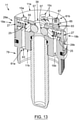
- the jounce adjustment component (19a) is positioned, shaped and sized with respect to the at least one active jounce fluid passage (15a) so that the default configuration of the jounce adjustment component (19a) corresponds to the fully-opened configuration of the jounce adjustment component (19a), as better shown in Figure 13 , for example.
- the jounce adjustment component (19a) may be positioned, shaped and sized with respect to the at least one active jounce fluid passage (15a) so that the default configuration of the jounce adjustment component (19a) corresponds to the fully-closed configuration of the jounce adjustment component (19a).
- the piston head (11) of the piston assembly (9) can comprise a jounce lodging passage (29a) being positioned, shaped and sized for receiving the jounce adjustment component (19a), the jounce lodging passage (29a) being further positioned, shaped and sized for fluidly intersecting the at least one active jounce fluid passage (15a).
- the at least one active jounce fluid passage (15a) can extend longitudinally along the piston head (11), and the jounce lodging passage (29a) can extend transversally with respect to the piston head (11).
- the jounce adjustment component (19a) can comprise a shouldering portion (31a) for resting against a corresponding abutment portion (33a) of the jounce lodging passage (29a) when the jounce adjustment component (19a) is in the default configuration.
- the jounce adjustment component (19a) is configured for adjustably moving in response to the input indicative of the positioning of the piston assembly (9) within the stroke distance (7) being received from said biasing assembly (21).
- the biasing assembly (21) can include a biasing component (35) provided with a jounce displacement-profile surface (35a) interacting with the jounce adjustment component (19a) for adjustably moving the jounce adjustment component (19a) with respect to the at least at least one active jounce fluid passage (15a) (ex. depending on a positioning of the jounce adjustment component (19a) with respect to the jounce displacement-profile surface (35a) of the biasing component (35), etc.).
- the chamber (13) containing the piston head (11) of the piston assembly (9) can be defined about a portion of the top mounting component (5), and the biasing component (35) with corresponding jounce displacement-profile surface (35a) can be mounted onto the top mounting component (5) and can be disposed along the chamber (13) of said top mounting component (5), as exemplified in the accompanying drawings.
- the biasing component (35) may include a profiled bar (37) being provided with the jounce displacement-profile surface (35a), and the profiled bar (37) may removably and pivotably mountable onto the top mounting component (5) via a corresponding attachment component (59), and may also be disposed centrally within the chamber (13) of the top mounting component (5), for example, although various other alternative disposition(s) and/or embodiment(s) are also be contemplated for the present system (1).
- the piston head (11) comprises a corresponding central hole (39) for receiving therethrough the profiled bar (37) of the biasing assembly (21) during a relative displacement of the bottom mounting component (5) with respect to the top mounting component (5).
- the piston head (11) may further comprise an interlocking component (41) disposed about the corresponding central hole (39) for interlocking with the profiled bar (37) during displacement of the profiled bar (37) through said corresponding central hole (39), and the interlocking component (41) may include a pin (41a) being removably mountable onto the piston head (11) via a fastener (43), the pin (41a) being positioned, shaped and sized for extending within the corresponding central hole (39) and for further fitting into a corresponding slot (41b) disposed about the profiled bar (37).
- the pin (41a) can be removably insertable into a corresponding receiving passage (85) defined about the piston head (11), for example, and the receiving passage (85) can be disposed transversally with respect to the piston head (11), and may extend from the central hole (39) of the piston head (11) to a side surface (11c) of the piston head (11), although various other alternative disposition(s) and/or embodiment(s), are also contemplated for the present system (1).
- the above-mentioned fastener (43) may be positioned, shaped and sized so that a top portion thereof is lodged within a corresponding recess (45) of the piston head (11) of the piston assembly (9), so as to prevent the top portion of the fastener (45) from exceeding beyond a top surface (11a) of said piston head (11).
- the position-relative damper assist system (1) can comprise a hollow separator component (47) being removably mountable onto the piston head (11), for use with an internal accumulator (49a), the hollow separator component (47) having an opened end operatively connectable to the corresponding central hole (39) of the piston head (11), and an opposite closed end for separating a fluid (51) of the internal accumulator (49a) from a fluid of the chamber (13).
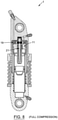
- the hollow separator component (47) is preferably made long enough for receiving the profiled bar (37) when the top and bottom mounting components (5,3) are operated in the "compression" mode (see Figure 8 , for example).
- the profiled bar (37) is preferably made long enough for interacting with the jounce adjustment component (19a) when the top and bottom mounting components (5,3) are operated in the "extension" mode (see Figure 9 , for example).
- the jounce adjustment component (19a) can include a spring-loaded plunger (53) having one end interacting with the jounce displacement-profile surface (35a) for moving in response to a corresponding contour of said jounce displacement-profile surface (35a).
- the jounce adjustment component (19a) can include a spring-loaded poppet (55) provided with an adjacent ball-bearing (57) interacting with the jounce displacement-profile surface (35a) for moving in response to a corresponding contour of said jounce displacement-profile surface (35a).
- the poppet (55) can also comprise a shouldering portion (31) for resting against a corresponding abutment portion (33), and a cross-sectional profile of the ball-bearing (57) is preferably made smaller than a cross-sectional profile of the poppet (55).
- the jounce displacement-profile surface (35a) is a curved jounce displacement-profile surface (35a) for providing at least two contact points to a corresponding component being operatively connected to the jounce adjustment component (19a).
- a jounce displacement-profile surface (35a) with only one contact point could also be used, and the fact that the jounce displacement-profile surface (35a) may be "curved" (and/or shaped otherwise, etc.) and provide a plurality of contact points (ex. two or more, etc.) is particularly advantageous for improved durability of the part(s), etc., when the adjustment assembly (19) and the biasing assembly (21) interact "mechanically", for example.
- the at least one active jounce fluid passage (15a) comprises a pair of active jounce fluid passages (15a) each for allowing fluid (17) of the chamber (13) to travel from one side of the chamber (13) to another side of the chamber via the piston head (11) of the piston assembly (9) during the compression mode
- the jounce adjustment component (19a) can be configured for adjustably varying an effective cross-sectional profile of both active jounce fluid passages (15a) in order to in turn vary a corresponding flow rate of fluid (17) passing through the pair of active jounce fluid passages (15a) during the compression mode.
- One end of the at least one active jounce fluid passage (15a) may be provided with a corresponding jounce shim assembly (61a) being configured for shimming fluid exiting said end of the at least one active jounce fluid passage (15a) during the compression mode.
- the jounce shim assembly (61a) can be further configured for preventing fluid from entering said end of the at least one active jounce fluid passage (15a) (for example, of each active jounce fluid passage (15a), etc.) during the "extension" mode.
- the jounce shim assembly (61a) may include a series of lamellae (63) being stackable onto one another, and the series of lamellae (63) may be nestable within a corresponding recess (65) defined about the piston head (11) of the piston assembly (9).
- the series of lamellae (63) can be secured onto the piston head (11) via at least one fastener (67), and the at least one fastener (67) is preferably positioned, shaped and sized so that a top portion thereof is prevented from exceeding beyond a top surface (11a) of the piston head (11) of the piston assembly (9).
- the at least one fastener (67) includes a pair of fasteners (67) configured for threaded engagement into the series of lamellae (63) and piston head (11), and the series of lamellae (63) may include a plurality of oblong lamellae (63) of different lengths, with a longest lamella (63) being positioned at a bottommost portion of the series of lamellae (63) and a shortest lamella (63) being positioned at an upper portion of the series of lamellae (63), each lamella (63) of the series of lamellae (63) being shorter than a preceding bottom lamella (63), for example.
- the at least one fluid passage (15) of the piston head (11) can also comprise at least one active rebound fluid passage (15b) for allowing fluid (17) of the chamber (13) to travel from one side of the chamber (13) to another side of the chamber (13) via the piston head (11) of the piston assembly (9) during the extension mode
- the adjustment assembly (19) can comprise a corresponding rebound adjustment component (19b) being configured for adjustably varying an effective cross-sectional profile of the at least one active rebound fluid passage (15b) in order to in turn vary a corresponding flow rate of fluid (17) passing through said at least one active rebound fluid passage (15b) during the extension mode.
- the rebound adjustment component (19b) can be a spring-loaded rebound adjustment component (19b), and the adjustment assembly (19) can thus comprise a corresponding spring (25) having one extremity operatively abutting against a given supporting component (27), and having another extremity operatively pushing against the rebound adjustment component (19b) for urging the rebound adjustment component (19b) into a given default configuration, the spring-loaded rebound adjustment component (19b) being adjustably operable via the biasing assembly (21) between variable opened and closed configurations, wherein in a fully-opened configuration, the rebound adjustment component (19b) is substantially clear from the at least one active rebound fluid passage (15b) in order to allow a maximal passage of fluid (17) through the at least one active rebound fluid passage (15b), and wherein in a fully-closed configuration, the rebound adjustment component (19b) substantially blocks the at least one active rebound fluid passage (15b) in order to allow a minimal passage of fluid (17) through the at least one active rebound fluid passage (15b).
- the rebound adjustment component (19b) is positioned, shaped and sized with respect to the at least one active rebound fluid passage (15b) so that the default configuration of the rebound adjustment component (19b) corresponds to the fully-opened configuration of the rebound adjustment component (19b), as better shown in Figure 13 , for example.
- the rebound adjustment component (19b) may be positioned, shaped and sized with respect to the at least one active rebound fluid passage (15b) so that the default configuration of the rebound adjustment component (19b) corresponds to the fully-closed configuration of the rebound adjustment component (19b).
- the piston head (11) of the piston assembly (9) can comprise a rebound lodging passage (29b) being positioned, shaped and sized for receiving the rebound adjustment component (19b), the rebound lodging passage (29b) being further positioned, shaped and sized for fluidly intersecting the at least one active rebound fluid passage (15b).
- the at least one active rebound fluid passage (15b) may extend longitudinally along the piston head (11), and whereas the rebound lodging passage (29b) may extend transversally with respect to the piston head (11).
- the rebound adjustment component (19b) can comprise a shouldering portion (31b) for resting against a corresponding abutment portion (33b) of the rebound lodging passage (29b) when the rebound adjustment component (19b) is in the default configuration.
- the rebound adjustment component (19b) is configured for adjustably moving in response to the input indicative of the positioning of the piston assembly (9) within the stroke distance (7) being received from the biasing assembly (21).
- the above-described single biasing component (35) (and/or a separate one) can be further provided with a rebound displacement-profile surface (35b) interacting with the rebound adjustment component (19b) for adjustably moving the rebound adjustment component (19b) with respect to the at least at least one active rebound fluid passage (15b) (ex. depending on a positioning of the rebound adjustment component (19b) with respect to the rebound displacement-profile surface (35b) of the biasing component (35), etc.).
- the biasing component (35) with corresponding rebound displacement-profile surface (35b) can be mounted onto the top mounting component (7) and can be disposed along the chamber of said top mounting component (7).
- the profiled bar (37) may be further provided with the rebound displacement-profile surface (35b), and is preferably made long enough for interacting with the rebound adjustment component (19b) when the top and bottom mounting components (5,3) are operated in the "extension" mode (see Figure 9 , for example).
- the rebound adjustment component (19b) can include a spring-loaded plunger (53) having one end interacting with the rebound displacement-profile surface (35b) for moving in response to a corresponding contour of said rebound displacement-profile surface (35b).
- the rebound adjustment component (19b) can include a spring-loaded poppet (55) provided with an adjacent ball-bearing (57) interacting with the rebound displacement-profile surface (35b) for moving in response to a corresponding contour of said rebound displacement-profile surface (35b).
- This poppet (55) can also comprise a shouldering portion (31) for resting against a corresponding abutment portion (33), and a cross-sectional profile of the ball-bearing (57) is preferably made smaller than a cross-sectional profile of the poppet (55).
- the rebound displacement-profile surface (35b) is a curved rebound displacement-profile surface (35b) for providing at least two contact points to a corresponding component being operatively connected to the rebound adjustment component (19b).
- the rebound displacement-profile surface (35b) may be provided with a single contact point, as previously discussed when referring to the "jounce" counterpart.
- the at least one active rebound fluid passage (15b) comprises a pair of active rebound fluid passages (15b) each for allowing fluid (17) of the chamber (13) to travel from one side of the chamber (13) to another side of the chamber (13) via the piston head (11) of the piston assembly (9) during the extension mode
- the rebound adjustment component (19b) can be configured for adjustably varying an effective cross-sectional profile of both active rebound fluid passages (15b) in order to in turn vary a corresponding flow rate of fluid (17) passing through the pair of active rebound fluid passages (15b) during the extension mode.
- One end of the at least one active rebound fluid passage (15b) may be provided with a corresponding rebound shim assembly (61b) being configured for shimming fluid (17) exiting said end of the at least one active rebound fluid passage (15b) during the "extension" mode.
- the rebound shim assembly (61b) can be further configured for preventing fluid (17) from entering said end of the at least one active rebound fluid passage (15b) (for example, of each active rebound fluid passage (15b), etc.) during the "compression" mode.
- the rebound shim assembly (61b) can have components and features similar to that of the jounce shim assembly (61a).
- such a directional control and/or flow of the fluid could be achieved via a "ball bearing” and a machined “seat", for example, in which flow can either travel around the ball bearing through the piston head, or the ball bearing becomes seated, blocking all flow through the desired passage (15,15a,15b), etc., as can be easily understood by a person skilled in the art.
- the at least one active jounce fluid passage (15a) and corresponding jounce adjustment component (19a) can be disposed on one side of the piston head (11), and the at least one active rebound fluid passage (15b) and corresponding rebound adjustment component (19b) can be disposed on another opposite side of the piston head (11), as better shown in Figure 13 , for example.
- the jounce lodging passage (29a) and the rebound lodging passage (29b) can be fluidly connected to one another, and the jounce lodging passage (29a) and the rebound lodging passage (29b) can be further fluidly connected to the corresponding central hole (39) of the piston head (11), as also exemplified in Figure 13 .
- the at least one fluid passage (15) of the piston head (11) can comprise at least one passive fluid passage (15c) for allowing fluid (17) of the chamber (13) to travel from one side of the chamber (13) to another side of the chamber via the piston head (11) of the piston assembly (9) during either one (and preferably, both) of the compression and extension modes.
- the at least one fluid passage (15) of the piston head (11) comprises a pair of passive fluid passages (15c) for allowing fluid (17) of the chamber (13) to travel from one side of the chamber (13) to another side of the chamber (13) via the piston head (11) of the piston assembly (9) during either one (and preferably, both) of the compression and extension modes.
- the at least one fluid passage (15) of the piston head (11) includes at least one fluid passage (15) being internal to the piston head (11) of the piston assembly (9), as exemplified in the accompanying figures, but according to alternative possible embodiments of the present system (1), the at least one fluid passage (15) of the piston head (11) can also and/or alternatively include at least one fluid passage (15) being external to the piston head (11) of the piston assembly (9).
- At least one of the top and bottom mounting components (5,3) is provided with an eyelet (69), and optionally, the top and bottom mounting components (5,3) are each provided with a corresponding eyelet (69), and the stroke distance (7) of the top and bottom mounting components (5,3) corresponds to an "eyelet-to-eyelet” distance.
- each eyelet (69) may also be provided with a corresponding bearing (71).
- the position-relative damper assist system (1) can comprise an outer-seal end cap (73) for sealingly closing an interface between the top and bottom mounting components (5,3), the chamber (13) can be operatively connected to at least one corresponding port (75) selected from the group consisting of bleed port (75a) and fill port (75b).
- the present system (1) may be used with and/or for a variety of different piston assemblies (9), but according to one possible embodiment, the piston assembly (9) can comprise a piston rod (77) operatively extending between the bottom mounting component (3) of the position-relative damper assist system (1) and the piston head (11) of the piston assembly (9), with the piston head (11) being removably mountable onto the piston rod (77), if so desired via threading, for example, and the piston head (11) may also comprise a mounting collar (79) extending from a bottom surface (11b) of the piston head (11), the mounting collar (79) being configured for securing onto the piston rod (77).
- the piston assembly (9) can comprise a piston rod (77) operatively extending between the bottom mounting component (3) of the position-relative damper assist system (1) and the piston head (11) of the piston assembly (9), with the piston head (11) being removably mountable onto the piston rod (77), if so desired via threading, for example, and the piston head (11) may also comprise a
- the piston rod (77) can comprise a hollow section being provided an internal accumulator (49a) having a floating piston head (81), and the floating piston head (81) may have a cross-sectional shape being complementary to that of an adjacent separator component (47), for allowing the floating piston head (81) to travel within a greater range for a same given length of the internal accumulator (49a), as better shown in Figure 5, for example.
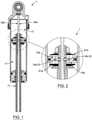
- Figures 1 and 2 show how the position-relative damper assist system (1) can comprise and/or be used with an external accumulator (49b) configured for cooperating with the piston assembly (9).
- the position-relative damper assist system (1) can comprise a shock-absorbing spring (83) interacting between the bottom and top mounting components (3,5), and the shock-absorbing spring (83) can be a coil spring having one end operatively secured to the top mounting component (5) (via a "spring seat” and/or any other suitable component, for example), and another end operatively secured to the bottom mounting component (3) (via a "retainer” and/or any other suitable component, for example).
- a kit with components for assembling a fully-assembled and fully-operational position-relative damper assist system (1) such as the one described and/or alluded to in the present patent specification, and accompanying drawings.
- a vehicle provided with such as position-relative damper assist system (1).
- the piston head (11) having one and/or several of the various components and/or features described and/or alluded to in the present patent specification, and accompanying drawings. According to yet another possible aspect of the present invention, there is also provided a kit with components for assembling such a piston head (11).
- the damping of the jounce orifice is achieved through the jounce profile tracking assembly (19a,53), which tracks/follows the contours of the damping profile rod - jounce (35a) located in the piston rod (77).
- the damping profile rod (35a,35b) is fixed at the rod attachment point (59), which allows it to rotate freely within the piston rod 77).
- the jounce profile tracking assembly (19a,53) follows the contours of the profile, opening/restricting the flow through the jounce orifice(s) (15a) as required.
- the profile details are selected to provide specific position-relative damping characteristics.
- the jounce profile tracking assembly (19a,53) can be preloaded in a way to ensure proper contact with the damping profile rod (35a,35b), naturally allowing full flow through the jounce orifices (15a) when the contour is smallest and greatest restriction when over profile peaks.
- the preload of the tracking assemblies (19a,53) can be achieved but is not limited to compression springs, wave springs, etc.
- the profile tracking assembly (19b,53) design details can vary in shape, size and quantity. In some instances, the design may be required to support a threshold flow rate/pressure in which some jounce/rebound orifices are not position specific.
- the motion of a single profile tracking assembly could adjust damping within numerous damping orifices, jounce or rebound, depending on functional requirements.
- the damping profile rod (35a,35b) can be adjusted to allow easy modification of damping characteristics relative to position. This could be achieved through an adjustment screw located on the bottom of the piston rod (77), for example.
- the jounce and rebound profiles can be application specific, and in some instances, may mimic one another.
- the cross-sectional design of the damping profile rod (35a,35b,37) could be a variety of shapes such as an 'X', square, or any other suitable and/or functionally equivalent shape, etc.
- "jounce” and “rebound” damping can be controlled through the inclusion of jounce (61a) and rebound (61b) shim stacks.
- the stacks limit flow in their respective directions of travel, effectively functioning as directional flow valves.
- the size of the orifices is influenced by the tracking profile assembly.
- the tracking profile assembly can be made as one device with profile on both side as shown on surface (35b) and surface (35a).
- the tracking profile assembly can also be made of two separate tracking profile assembly.
- An adjustment mechanism made of one adjustment knob or two adjustment knobs could also be used to pre-set the static position of the position damping. The adjustment mechanism could also be used to operate the knobs, etc.
- the present invention is a substantial improvement over the damping systems of the prior art in that, by virtue of its design and components, as briefly explained herein, the present system enables to overcome or at least minimize some of the known drawbacks associated with conventional systems, providing for a simpler, easier, faster, more accurate, more effective, more functional, more reliable and/or more versatile position-relative damper assist system than what is possible with other conventional systems.
- the present position-relative damper assist system and corresponding parts are preferably made of substantially rigid materials, such as metallic materials, hardened polymers, composite materials, polymeric materials (ex. seals, etc.), and/or the like, so as to ensure a proper operation thereof depending on the particular applications for which the position-relative damper assist system is intended and the different parameters (forces, moments, etc.) in cause, as apparent to a person skilled in the art.
Description
- The present invention relates to the field of shock-absorber assemblies. More particularly, and according to a possible intended use, the present invention relates to a position-relative damper assist system, and also relates to a kit with corresponding components for assembling the same, to a resulting shock-absorber assembly and corresponding vehicle provided with such a damper assist system, and to corresponding methods of manufacturing, assembling and/or operating associated thereto.
- Shock absorbers are well known in the art.
- Indeed, conventional shock-absorbers generally comprise a hydraulic circuit or path containing fluid (typically "oil") for carrying out a damping of shocks that a vehicle may be subjected to when travelling over a given terrain. Essentially, the damping of shocks is done via a restriction of the fluid contained in the hydraulic path of the shock absorber.
- Also known in the art are conventional shock-absorbers that rely on a compression of an elastic object (ex. a "spring") for carrying out a corresponding damping of shocks.
- Also known in the art are conventional shock absorbers that rely on a combined effect of both a compression of fluid and a compression of a spring.
- It is also known in the art that for certain conventional shock-absorbers, when the shock compresses, the movement of a corresponding shaft will displace a certain amount of hydraulic fluid (ex. "oil"). This displaced oil will pass through adjustments (ex. "shims"). The range of these adjustments can vary the opening of the flow channels for the oil to pass therethrough. If the passage is smaller or reduced, then the oil will encounter more resistance to flow therethrough. If the passage is larger or increased, then the oil will encounter less resistance to flow therethrough. This resistance will permit the shock to absorb a certain amount of energy, depending on the particular static and/or dynamic loads to which the vehicle, including such a conventional shock absorber, is subjected to.
- Known to the Applicants are the following US patents which describe various devices (dampers, stabilizers, shock absorbers, etc.) for use with motorbikes, ATVs and the like: 1,628,811; 1,957,997; 2,009,678; 4,773,514; 5,044,614; 5,516,133; and 6,401,884 B2.
- It is also known in the art that there are various preload systems for mechanical springs that are currently available on the market. These preload systems are typically used for motorcycles. Generally, an adjusting knob is used to manually move a piston which will displace a fluid into a chamber, said chamber can expand or retract to compensate for displacement changes of the fluid. The preload piston can be placed remotely from the chamber to ease the accessibility of the knob. Fluid from the piston to the chamber will be connected typically with a hose.
- Track systems are also well known in the art.
- For example, belonging to the co-Applicant of the present case is
US Patent No. 7,556,130 B2 granted on July 7th, 2009, to Lamoureux et al. There is described a track system for providing complementary shock absorbing capability to a primary shock absorbing assembly having a hydraulic path containing fluid. The track system includes a chamber, a damping assembly and an adjusting assembly. The chamber has opposite first and second ends, the first end of the chamber being provided with a port operatively connectable to the hydraulic path of the primary shock absorbing assembly, the port being configured for allowing fluid from the hydraulic path of the primary shock absorbing assembly to enter and exit the chamber of the track system through the port thereof. The damping assembly is configured for damping a flow of fluid entering the chamber via the port thereof. The adjusting assembly is configured for adjusting a damping mode of the damping assembly. - Dual inline hydraulic devices are also well known in the art.
- For example, also belonging to the co-Applicant of the present case is
US Patent No. 9,573,435 B2 granted on February 21st, 2007, to Lamoureux et al - In addition to the above-discussed conventional shock-absorber assemblies and damping systems, position-sensitive dampers are also well known in the art.
- For example, known to the Applicants are the following patent documents:
US 4,153,237 ;US 4,624,346 ;US 4,798,398 ;US 5,810,128 ;US 6,296,092 B1 ;US 6,415,895 B2 ;US 6,880,684 B1 ;US 6,966,412 B2 ;US 7,128,192 B2 ;US 7,273,137 B2 ;US 7,374,028 B2 ;US 7,628,259 B2 ;US 7,690,666 B2 ;US 8,764,029 B2 ;US 8,807,299 B2 ;US 2009/0277734 A1 ;US 2010/0059321 A1 ;US 2010/0170760 A1 ;US 2011/0214956 A1 ;US 2011/0315494 A1 ;US 2012/0018263 A1 ;US 2012/0048665 A1 ;US 2012/0222927 A1 ;US 2012/0305350 A1 ;US 2013/0228404 A1 ;US 2013/0292218 A1 ;US 20014/0008160 A1 US 2014/0124312 A1 ;EP 1,754,909 A1 ;EP 2,116,739 A2 ;EP 2,402,626 A2 ;EP 2,410,203 A2 ;EP 2,495,472 A2 ;EP 2,530,355 A2 ;WO 00/79148 A2WO 2008/086605 A1 - Also known in the art the various drawbacks associated with such conventional position-sensitive dampers.
- For example, current existing position-sensitive designs incorporate "jounce" (i.e. compression) and "rebound" (i.e. "extension") characteristics as one, with minimal deviation in damping control difference between the two. In addition, existing position-sensitive dampers do not have the capability to adjust externally and/or remotely the static position of the position sensitive mechanism to compensate for weight variations of the vehicle payload. Unfortunately, this limits the shock-absorber from having two very distinct damping curves between "jounce" and "rebound".
- Also, some position-sensitive dampers rely on the principle of "concentric tubes" (i.e. "double-walls") (see for example, video at the following link: http://www.ridefox.com/technology.php?m=utv&t=ibp&ref=topnav), and such a design is not optimal for obvious reasons (for example, it is harder, longer and more costly to manufacture, assembly, inspect, maintain, and/or repair, etc.), and the resulting dynamic behavior curve of the position-sensitive damper may be subject to undesirable/abrupt "steps" as the peripheral by-pass ports are passed by the piston, as a result of "jumps" in flow rate due to the inherent nature of the construction design, etc.
- Thus, it would be particularly useful to be able to provide an improved system which, by virtue of its design and components, would be able to overcome or at least minimize some of these known drawbacks associated with conventional systems.
-
US 4,061,295 A discloses a position-relative damper assist system according to the preamble ofclaim 1. - An object of the present invention is to provide a position-relative damper assist system which, by virtue of its design and components, satisfies some of the above-mentioned need(s), and which is thus an improvement over other related damping systems and/or methods known in the prior art.
- In accordance with the present invention, the above object is achieved, as will be easily understood from the present description, with a position-relative damper assist system (also referred to herein simply as "damping system" or "position-sensitive damper") such as the one briefly described herein and such as the one exemplified in the accompanying drawings.
- More particularly, according to one aspect of the present invention as defined in
claim 1, an object is to provide a position-relative damper assist system for use with a vehicle, the position-relative damper assist system comprising: - top and bottom mounting components cooperating with one another to define a corresponding stroke distance between them, and being operable with respect to one another between compression and extension modes along said stroke distance, the top mounting component being operatively connectable to a frame of the vehicle, and the bottom mounting component being operatively connectable to a supporting component of the vehicle;
- a piston assembly being operatively disposed between the top and bottom mounting components, the piston assembly having a piston head being displaceable within a chamber defined about a portion of one of the top and bottom mounting components, the piston head being provided with at least one fluid passage for allowing fluid of the chamber to travel from one side of the chamber to another side of the chamber via the piston head of the piston assembly, in order to provide a corresponding damping effect;
- an adjustment assembly cooperating with the piston head of the piston assembly for adjustably varying an effective cross-sectional profile of the at least one fluid passage in order to in turn vary a corresponding flow rate of fluid passing through said at least one fluid passage, and in turn vary the resulting damping effect; and
- a biasing assembly cooperating with the adjustment assembly for selectively varying a configuration of the adjustment assembly in response to a given input indicative of the positioning of the piston assembly within the stroke distance, in order in vary the resulting damping effect in response to a corresponding displacement-profile provided by the biasing assembly.
- The adjustment assembly is contained inside the piston head, and configured to adjustably vary the effective cross-sectional profile of the at least one fluid passage inside said piston head.
- According to another aspect of the present invention, there is provided a shock-absorber assembly provided with the above-mentioned damper assist system.
- According to another aspect of the present invention, there is provided a vehicle provided with the above-mentioned damper assist system and/or corresponding shock-absorber assembly.
- According to another aspect of the invention, there is also provided a method of assembling and/or mounting the above-mentioned damper assist system onto a corresponding shock-absorber assembly and/or vehicle.
- According to yet another aspect of the invention, there is also provided a method of using the above-mentioned damper assist system, shock-absorber assembly and/or corresponding vehicle.
- According to yet another aspect of the invention, there is also provided a kit with components for assembling the above-mentioned damper assist system, shock-absorber assembly and/or corresponding vehicle.
- According to yet another aspect of the present invention, there is also provided a set of components for interchanging with components of the above-mentioned kit.
- According to yet another aspect of the present invention, there is also provided a method of assembling components of the above-mentioned kit and/or set.
- According to yet another aspect of the present invention, there is also provided a method of doing business with the above-mentioned damper assist system, shock-absorber assembly, vehicle, components thereof, kit, set and/or method (s).
- The objects, advantages, and other features of the present invention will become more apparent upon reading of the following non-restrictive description of preferred embodiments thereof, given for the purpose of exemplification only, with reference to the accompanying drawings.
-
-
Figure 1 is a cross-sectional representation of a shock-absorber assembly intended to be used with an external accumulator (if desired), and provided with a position-relative damper assist system according to a possible embodiment of the present invention. -
Figure 2 is an enlarged view of a portion of what is shown inFigure 1 . - Figures 3
-23 are different views of various aspects, components and features of possible position-relative damper assist systems and/or different configurations thereof according to other possible embodiments of the present invention. - In the following description, the same numerical references refer to similar elements. Furthermore, for sake of simplicity and clarity, namely so as to not unduly burden the figures with several reference numbers, only some figures have been provided with reference numbers, and components and features of the present invention illustrated in other figures can be easily inferred therefrom. The embodiments, geometrical configurations, materials mentioned and/or dimensions shown in the figures are preferred, for exemplification purposes only.
- Moreover, although the present invention was primarily designed for use within a shock-absorber assembly of a vehicle for position-relative damping purposes, it may be used with other objects and/or in other types of applications, as apparent to a person skilled in the art. For this reason, expressions such as "shock-absorber", "assembly", "vehicle", "position-relative", "damping", etc., used herein should not be taken so as to limit the scope of the present invention and include all other kinds of objects and/or applications with which the present invention could be used and may be useful. For example, the present position-relative damper assist system could also be used with and/or for "rotary dampers", for instance, given that the same principle or system could be easily adapted to this type of damper, as well.
- Moreover, in the context of the present invention, the expressions "shock-absorber", "suspension", "assembly", "damping", "damper", "system", "device", "dissipation", "dissipator", "apparatus", "product", "unit", "equipment", "tool", "method" and "kit", as well as any other equivalent expressions and/or compounds word thereof known in the art will be used interchangeably, as apparent to a person skilled in the art. This applies also for any other mutually equivalent expressions, such as, for example: a) "position-sensitive"; "position-relative", "position-indicative", "position-representative", etc.; b) "shock-absorber", "suspension", "damper", etc.; c) "stroke", "travel", "range", "motion", etc.; d) "distance", "position", "location", etc.; e) "passage", "channel", "conduit", "path", "orifice", "hole", "flow", etc.; f) "fastening", "securing", "restraining", "affixing", "holding", "adjusting", etc.; as well as for any other mutually equivalent expressions, pertaining to the aforementioned expressions and/or to any other structural and/or functional aspects of the present invention, as also apparent to a person skilled in the art. Also, in the context of the present description, expressions such as "can", "may", "might", "will", "could", "should", "would", etc., may also be used interchangeably, whenever appropriate, as also apparent to a person skilled in the art.
- Furthermore, in the context of the present description, it will be considered that all elongated objects will have an implicit "longitudinal axis" or "centerline", such as the longitudinal axis of shaft for example, or the centerline of a coiled spring, for example, and that expressions such as "connected" and "connectable", or "mounted" and "mountable", may be interchangeable, in that the present invention also relates to a kit with corresponding components for assembling a resulting fully-assembled and fully-operational damping system (and/or a resulting fully-assembled and fully-operational shock-absorber assembly and/or vehicle provided with the same, etc.).
- Moreover, components of the present system(s) and/or steps of the method(s) described herein could be modified, simplified, altered, omitted and/or interchanged, without departing from the scope of the present invention, depending on the particular applications which the present invention is intended for, and the desired end results, as briefly exemplified herein and as also apparent to a person skilled in the art.
- In addition, although the preferred embodiments of the present invention as illustrated in the accompanying drawings comprise various components, and although the preferred embodiments of the present position-relative damper assist system and corresponding portion(s)/part(s)/component(s) as shown consist of certain geometrical configurations, as explained and illustrated herein, not all of these components and geometries are essential to the invention and thus should not be taken in their restrictive sense, i.e. should not be taken so as to limit the scope of the present invention. It is to be understood, as also apparent to a person skilled in the art, that other suitable components and cooperation thereinbetween, as well as other suitable geometrical configurations may be used for the present position-relative damper assist system and corresponding portion(s)/part(s)/component(s) according to the present invention, as will be briefly explained herein and as can be easily inferred herefrom by a person skilled in the art, without departing from the scope of the present invention.
- Broadly described, and as better exemplified in the accompanying drawings, the present invention relates to a damping system in order to provide a position-sensitive damping, in a simpler, easier, faster, more accurate, more effective, more functional, more reliable and/or more versatile manner than what is possible with other conventional systems.
-
- 1.
- position-relative damper assist system (or "damping system")
- 3.
- bottom mounting component
- 5.
- top mounting component
- 7.
- stroke distance (or "travel" distance)
- 9.
- piston assembly
- 11.
- piston head
- 11a.
- top surface (of piston head)
- 11b.
- bottom surface (of piston head)
- 11c.
- side surface (of piston head)
- 13.
- chamber
- 15.
- fluid passage (of piston head)
- 15a.
- active jounce fluid passage
- 15b.
- active rebound fluid passage
- 15c.
- passive fluid passage
- 17.
- fluid (ex. "oil")
- 19.
- adjustment assembly
- 19a.
- jounce adjustment component (of adjustment assembly)
- 19b.
- rebound adjustment component (of adjustment assembly)
- 21.
- biasing assembly
- 23.
- displacement-profile
- 25.
- spring
- 27.
- supporting component (for spring)
- 29.
- lodging passage
- 29a.
- jounce lodging passage
- 29b.
- rebound lodging passage
- 31.
- shouldering portion
- 31a.
- jounce shouldering portion
- 31b.
- rebound shouldering portion
- 33.
- abutment portion
- 33a.
- jounce abutment portion
- 33b.
- rebound abutment portion
- 35.
- biasing component
- 35a.
- jounce displacement-profile surface (of biasing component)
- 35b.
- rebound displacement-profile surface (of biasing component)
- 37.
- profiled bar
- 39.
- central hole (of piston head)
- 41.
- interlocking component
- 41a.
- pin (of interlocking component)
- 41b.
- slot (for pin)
- 43.
- fastener (for pin)
- 45.
- recess (for fastener)
- 47.
- separator component
- 49.
- accumulator
- 49a.
- internal accumulator
- 49b.
- external accumulator
- 51.
- fluid (of accumulator - ex. "nitrogen")
- 53.
- plunger
- 55.
- poppet
- 57.
- ball-bearing
- 61.
- shim assembly (or "shim stack")
- 61a.
- jounce shim assembly
- 61b.
- rebound shim assembly
- 63.
- lamella
- 65.
- recess (for lamella)
- 67.
- fastener (for lamella)
- 69.
- eyelet
- 71.
- bearing (of eyelet)
- 73.
- outer-seal end cap
- 75.
- port
- 75a.
- bleed port
- 75b.
- fill port
- 77.
- piston rod
- 79.
- mounting collar (of piston head)
- 81.
- floating piston head (of internal accumulator)
- 83.
- shock-absorbing spring (i.e. coiled spring)
- 85.
- receiving passage (for pin)
- As previously explained, current existing position-sensitive designs incorporate "jounce" and "rebound" characteristics as one, with minimal deviation in damping control difference between the two. In addition, existing position-sensitive dampers do not have the capability to adjust externally and/or remotely the static position of the position sensitive mechanism to compensate for weight variations of the vehicle payload. Unfortunately, this limits the shock-absorber from having two very distinct damping curves between "jounce" and "rebound".
- In contrast, and broadly described, the present invention, as exemplified in the accompanying drawings, relates to a damping system (i.e. "position-relative damper assist system", etc.) designed in such a way to remove this similarity and allow damping curves to reflect what is required to achieve best performances for ride quality and handling. By integrating the design within the piston and rod assembly, for example, the need for double-wall or external bypass tubes assemblies is removed. The design can easily be integrated with existing technology which does not currently make use of this space.
- The present position-relative damper assist system (1) may come in the form of a damper assist system (1) including one and/or several of the following possible components and features (and/or different possible combination(s) and/or permutation(s) thereof):
Indeed, according to one possible embodiment, and as can be easily understood when referring to the accompanying drawings, there is provided a position-relative damper assist system (1) for use with a vehicle (whether the vehicle be provided with wheel(s), skid(s), track(s), and/or etc.). The position-relative damper assist system (1) may comprise top and bottom mounting components (5,3) cooperating with one another to define a corresponding "stroke" distance (7) (or "travel" distance) between them, and being operable with respect to one another between compression (i.e. "jounce") and extension (i.e. "rebound") modes along said stroke distance, the top mounting component (5) being operatively connectable to a frame of the vehicle, and the bottom mounting component (5) being operatively connectable to a supporting component of the vehicle. The position-relative damper assist system (1) may also comprise a piston assembly (9) being operatively disposed between the top and bottom mounting components (5,3), the piston assembly (9) having a piston head (11) being displaceable within a chamber (13) defined about a portion of one of the top and bottom mounting components (5,3), the piston head (11) being provided with at least one fluid passage (15) for allowing fluid (17) of the chamber (13) to travel from one side of the chamber (13) to another side of the chamber (13) via the piston head (11) of the piston assembly (9), in order to provide a corresponding damping effect. The position-relative damper assist system (1) also comprises an adjustment assembly (19) (whether mechanical, electro-mechanical, electro-magnetic, magnetized (ex. with magnets, etc.), electric, computerized, other, and/or a combination thereof, etc.) cooperating with the piston head (11) of the piston assembly (9) for adjustably varying an effective cross-sectional profile of the at least one fluid passage (15) in order to in turn vary a corresponding flow rate of fluid (17) passing through said at least one fluid passage (15), and in turn vary the resulting damping effect. The position-relative damper assist system (1) also comprises a biasing assembly (21) (whether mechanical, electro-mechanical, electro-magnetic, magnetized (ex. with magnets, etc.), electric, computerized, other, and/or a combination thereof, etc.) cooperating with the adjustment assembly (19) for selectively varying a configuration of the adjustment assembly (19) in response to a given input indicative of the positioning of the piston assembly (9) within the stroke distance (7), in order in vary the resulting damping effect in response to a corresponding displacement-profile (23) provided by the biasing assembly (21). - Other possible aspect(s), object(s), embodiment(s), variant(s), and/or resulting advantage(s) of the position-relative damper assist system (1), all being preferred and/or optional, are briefly explained hereinbelow, and can be easily understood and/or inferred from the accompanying drawings, as well.
- For example, the at least one fluid passage (15) of the piston head (11) can comprise at least one active jounce fluid passage (15a) for allowing fluid (17) of the chamber (13) to travel from one side of the chamber (13) to another side of the chamber via the piston head (11) of the piston assembly (9) during the compression mode, and the adjustment assembly (19) can comprise a corresponding jounce adjustment component (19a) being configured for adjustably varying an effective cross-sectional profile of the at least one active jounce fluid passage (15a) in order to in turn vary a corresponding flow rate of fluid (17) passing through said at least one active jounce fluid passage (15a) during the compression mode.
- The jounce adjustment component (19a) can be a spring-loaded jounce adjustment component (19a), and the adjustment assembly (19) can thus comprise a corresponding spring (25) having one extremity operatively abutting against a given supporting component (27), and having another extremity operatively pushing against the jounce adjustment component (19a) for urging the jounce adjustment component (19a) into a given default configuration, the spring-loaded jounce adjustment component (19a) being adjustably operable via the biasing assembly (21) between variable opened and closed configurations, wherein in a fully-opened configuration, the jounce adjustment component (19a) is substantially clear from the at least one active jounce fluid passage (15a) in order to allow a maximal passage of fluid (17) through the at least one active jounce fluid passage (15a), and wherein in a fully-closed configuration, the jounce adjustment component (19a) substantially blocks the at least one active jounce fluid passage (15a) in order to allow a minimal passage of fluid (17) through the at least one active jounce fluid passage (15a).
- In one possible embodiment, the jounce adjustment component (19a) is positioned, shaped and sized with respect to the at least one active jounce fluid passage (15a) so that the default configuration of the jounce adjustment component (19a) corresponds to the fully-opened configuration of the jounce adjustment component (19a), as better shown in
Figure 13 , for example. - Alternatively, the jounce adjustment component (19a) may be positioned, shaped and sized with respect to the at least one active jounce fluid passage (15a) so that the default configuration of the jounce adjustment component (19a) corresponds to the fully-closed configuration of the jounce adjustment component (19a).
- As shown in the accompanying figures, the piston head (11) of the piston assembly (9) can comprise a jounce lodging passage (29a) being positioned, shaped and sized for receiving the jounce adjustment component (19a), the jounce lodging passage (29a) being further positioned, shaped and sized for fluidly intersecting the at least one active jounce fluid passage (15a).
- The at least one active jounce fluid passage (15a) can extend longitudinally along the piston head (11), and the jounce lodging passage (29a) can extend transversally with respect to the piston head (11).
- As better shown in
Figures 13 and14 , for example, the jounce adjustment component (19a) can comprise a shouldering portion (31a) for resting against a corresponding abutment portion (33a) of the jounce lodging passage (29a) when the jounce adjustment component (19a) is in the default configuration. - Irrespective of the nature of the biasing assembly (21) being used for the present system (1), whether it be mechanical, electro-mechanical, electro-magnetic, magnetized (ex. with magnets, etc.), electric, computerized, other, and/or a combination thereof, etc.), the jounce adjustment component (19a) is configured for adjustably moving in response to the input indicative of the positioning of the piston assembly (9) within the stroke distance (7) being received from said biasing assembly (21).
- The biasing assembly (21) can include a biasing component (35) provided with a jounce displacement-profile surface (35a) interacting with the jounce adjustment component (19a) for adjustably moving the jounce adjustment component (19a) with respect to the at least at least one active jounce fluid passage (15a) (ex. depending on a positioning of the jounce adjustment component (19a) with respect to the jounce displacement-profile surface (35a) of the biasing component (35), etc.).
- The chamber (13) containing the piston head (11) of the piston assembly (9) can be defined about a portion of the top mounting component (5), and the biasing component (35) with corresponding jounce displacement-profile surface (35a) can be mounted onto the top mounting component (5) and can be disposed along the chamber (13) of said top mounting component (5), as exemplified in the accompanying drawings.
- In its simplest form (ex. a mechanical version, etc.), the biasing component (35) may include a profiled bar (37) being provided with the jounce displacement-profile surface (35a), and the profiled bar (37) may removably and pivotably mountable onto the top mounting component (5) via a corresponding attachment component (59), and may also be disposed centrally within the chamber (13) of the top mounting component (5), for example, although various other alternative disposition(s) and/or embodiment(s) are also be contemplated for the present system (1).
- According to one possible embodiment, the piston head (11) comprises a corresponding central hole (39) for receiving therethrough the profiled bar (37) of the biasing assembly (21) during a relative displacement of the bottom mounting component (5) with respect to the top mounting component (5).
- The piston head (11) may further comprise an interlocking component (41) disposed about the corresponding central hole (39) for interlocking with the profiled bar (37) during displacement of the profiled bar (37) through said corresponding central hole (39), and the interlocking component (41) may include a pin (41a) being removably mountable onto the piston head (11) via a fastener (43), the pin (41a) being positioned, shaped and sized for extending within the corresponding central hole (39) and for further fitting into a corresponding slot (41b) disposed about the profiled bar (37). The pin (41a) can be removably insertable into a corresponding receiving passage (85) defined about the piston head (11), for example, and the receiving passage (85) can be disposed transversally with respect to the piston head (11), and may extend from the central hole (39) of the piston head (11) to a side surface (11c) of the piston head (11), although various other alternative disposition(s) and/or embodiment(s), are also contemplated for the present system (1).
- The above-mentioned fastener (43) may be positioned, shaped and sized so that a top portion thereof is lodged within a corresponding recess (45) of the piston head (11) of the piston assembly (9), so as to prevent the top portion of the fastener (45) from exceeding beyond a top surface (11a) of said piston head (11).
- According to the embodiment(s) illustrated in Figures 3
-16 , the position-relative damper assist system (1) can comprise a hollow separator component (47) being removably mountable onto the piston head (11), for use with an internal accumulator (49a), the hollow separator component (47) having an opened end operatively connectable to the corresponding central hole (39) of the piston head (11), and an opposite closed end for separating a fluid (51) of the internal accumulator (49a) from a fluid of the chamber (13). - As shown, the hollow separator component (47) is preferably made long enough for receiving the profiled bar (37) when the top and bottom mounting components (5,3) are operated in the "compression" mode (see
Figure 8 , for example). - Similarly, the profiled bar (37) is preferably made long enough for interacting with the jounce adjustment component (19a) when the top and bottom mounting components (5,3) are operated in the "extension" mode (see
Figure 9 , for example). - In one alternative (as better shown in
Figures 1 and 2 ), the jounce adjustment component (19a) can include a spring-loaded plunger (53) having one end interacting with the jounce displacement-profile surface (35a) for moving in response to a corresponding contour of said jounce displacement-profile surface (35a). - In another alternative (as better shown in Figures 3-23), the jounce adjustment component (19a) can include a spring-loaded poppet (55) provided with an adjacent ball-bearing (57) interacting with the jounce displacement-profile surface (35a) for moving in response to a corresponding contour of said jounce displacement-profile surface (35a).
- The poppet (55) can also comprise a shouldering portion (31) for resting against a corresponding abutment portion (33), and a cross-sectional profile of the ball-bearing (57) is preferably made smaller than a cross-sectional profile of the poppet (55).
- According to another possible embodiment, the jounce displacement-profile surface (35a) is a curved jounce displacement-profile surface (35a) for providing at least two contact points to a corresponding component being operatively connected to the jounce adjustment component (19a). As can be easily understood, a jounce displacement-profile surface (35a) with only one contact point could also be used, and the fact that the jounce displacement-profile surface (35a) may be "curved" (and/or shaped otherwise, etc.) and provide a plurality of contact points (ex. two or more, etc.) is particularly advantageous for improved durability of the part(s), etc., when the adjustment assembly (19) and the biasing assembly (21) interact "mechanically", for example.
- According to another possible embodiment, the at least one active jounce fluid passage (15a) comprises a pair of active jounce fluid passages (15a) each for allowing fluid (17) of the chamber (13) to travel from one side of the chamber (13) to another side of the chamber via the piston head (11) of the piston assembly (9) during the compression mode, and the jounce adjustment component (19a) can be configured for adjustably varying an effective cross-sectional profile of both active jounce fluid passages (15a) in order to in turn vary a corresponding flow rate of fluid (17) passing through the pair of active jounce fluid passages (15a) during the compression mode.
- One end of the at least one active jounce fluid passage (15a) may be provided with a corresponding jounce shim assembly (61a) being configured for shimming fluid exiting said end of the at least one active jounce fluid passage (15a) during the compression mode.
- The jounce shim assembly (61a) can be further configured for preventing fluid from entering said end of the at least one active jounce fluid passage (15a) (for example, of each active jounce fluid passage (15a), etc.) during the "extension" mode.
- The jounce shim assembly (61a) may include a series of lamellae (63) being stackable onto one another, and the series of lamellae (63) may be nestable within a corresponding recess (65) defined about the piston head (11) of the piston assembly (9). The series of lamellae (63) can be secured onto the piston head (11) via at least one fastener (67), and the at least one fastener (67) is preferably positioned, shaped and sized so that a top portion thereof is prevented from exceeding beyond a top surface (11a) of the piston head (11) of the piston assembly (9).
- According to another possible embodiment, the at least one fastener (67) includes a pair of fasteners (67) configured for threaded engagement into the series of lamellae (63) and piston head (11), and the series of lamellae (63) may include a plurality of oblong lamellae (63) of different lengths, with a longest lamella (63) being positioned at a bottommost portion of the series of lamellae (63) and a shortest lamella (63) being positioned at an upper portion of the series of lamellae (63), each lamella (63) of the series of lamellae (63) being shorter than a preceding bottom lamella (63), for example.
- According to another aspect of the present system (1), the at least one fluid passage (15) of the piston head (11) can also comprise at least one active rebound fluid passage (15b) for allowing fluid (17) of the chamber (13) to travel from one side of the chamber (13) to another side of the chamber (13) via the piston head (11) of the piston assembly (9) during the extension mode, and the adjustment assembly (19) can comprise a corresponding rebound adjustment component (19b) being configured for adjustably varying an effective cross-sectional profile of the at least one active rebound fluid passage (15b) in order to in turn vary a corresponding flow rate of fluid (17) passing through said at least one active rebound fluid passage (15b) during the extension mode.
- The rebound adjustment component (19b) can be a spring-loaded rebound adjustment component (19b), and the adjustment assembly (19) can thus comprise a corresponding spring (25) having one extremity operatively abutting against a given supporting component (27), and having another extremity operatively pushing against the rebound adjustment component (19b) for urging the rebound adjustment component (19b) into a given default configuration, the spring-loaded rebound adjustment component (19b) being adjustably operable via the biasing assembly (21) between variable opened and closed configurations, wherein in a fully-opened configuration, the rebound adjustment component (19b) is substantially clear from the at least one active rebound fluid passage (15b) in order to allow a maximal passage of fluid (17) through the at least one active rebound fluid passage (15b), and wherein in a fully-closed configuration, the rebound adjustment component (19b) substantially blocks the at least one active rebound fluid passage (15b) in order to allow a minimal passage of fluid (17) through the at least one active rebound fluid passage (15b).
- In one possible embodiment, the rebound adjustment component (19b) is positioned, shaped and sized with respect to the at least one active rebound fluid passage (15b) so that the default configuration of the rebound adjustment component (19b) corresponds to the fully-opened configuration of the rebound adjustment component (19b), as better shown in
Figure 13 , for example. - Alternatively, the rebound adjustment component (19b) may be positioned, shaped and sized with respect to the at least one active rebound fluid passage (15b) so that the default configuration of the rebound adjustment component (19b) corresponds to the fully-closed configuration of the rebound adjustment component (19b).
- As shown in the accompanying figures, the piston head (11) of the piston assembly (9) can comprise a rebound lodging passage (29b) being positioned, shaped and sized for receiving the rebound adjustment component (19b), the rebound lodging passage (29b) being further positioned, shaped and sized for fluidly intersecting the at least one active rebound fluid passage (15b).
- The at least one active rebound fluid passage (15b) may extend longitudinally along the piston head (11), and whereas the rebound lodging passage (29b) may extend transversally with respect to the piston head (11).
- As better shown in
Figures 13 and14 , the rebound adjustment component (19b) can comprise a shouldering portion (31b) for resting against a corresponding abutment portion (33b) of the rebound lodging passage (29b) when the rebound adjustment component (19b) is in the default configuration. - The rebound adjustment component (19b) is configured for adjustably moving in response to the input indicative of the positioning of the piston assembly (9) within the stroke distance (7) being received from the biasing assembly (21).
- The above-described single biasing component (35) (and/or a separate one) can be further provided with a rebound displacement-profile surface (35b) interacting with the rebound adjustment component (19b) for adjustably moving the rebound adjustment component (19b) with respect to the at least at least one active rebound fluid passage (15b) (ex. depending on a positioning of the rebound adjustment component (19b) with respect to the rebound displacement-profile surface (35b) of the biasing component (35), etc.).
- Similarly to what was discussed above, the biasing component (35) with corresponding rebound displacement-profile surface (35b) can be mounted onto the top mounting component (7) and can be disposed along the chamber of said top mounting component (7). Also, the profiled bar (37) may be further provided with the rebound displacement-profile surface (35b), and is preferably made long enough for interacting with the rebound adjustment component (19b) when the top and bottom mounting components (5,3) are operated in the "extension" mode (see
Figure 9 , for example). - In one alternative embodiment (as better shown in
Figures 1 and 2 ), the rebound adjustment component (19b) can include a spring-loaded plunger (53) having one end interacting with the rebound displacement-profile surface (35b) for moving in response to a corresponding contour of said rebound displacement-profile surface (35b). - In another alternative embodiment (as better shown in Figures 3
-23 ), the rebound adjustment component (19b) can include a spring-loaded poppet (55) provided with an adjacent ball-bearing (57) interacting with the rebound displacement-profile surface (35b) for moving in response to a corresponding contour of said rebound displacement-profile surface (35b). - This poppet (55) can also comprise a shouldering portion (31) for resting against a corresponding abutment portion (33), and a cross-sectional profile of the ball-bearing (57) is preferably made smaller than a cross-sectional profile of the poppet (55).
- According to another possible embodiment, the rebound displacement-profile surface (35b) is a curved rebound displacement-profile surface (35b) for providing at least two contact points to a corresponding component being operatively connected to the rebound adjustment component (19b). The rebound displacement-profile surface (35b) may be provided with a single contact point, as previously discussed when referring to the "jounce" counterpart.
- According to another possible embodiment, the at least one active rebound fluid passage (15b) comprises a pair of active rebound fluid passages (15b) each for allowing fluid (17) of the chamber (13) to travel from one side of the chamber (13) to another side of the chamber (13) via the piston head (11) of the piston assembly (9) during the extension mode, and the rebound adjustment component (19b) can be configured for adjustably varying an effective cross-sectional profile of both active rebound fluid passages (15b) in order to in turn vary a corresponding flow rate of fluid (17) passing through the pair of active rebound fluid passages (15b) during the extension mode.
- One end of the at least one active rebound fluid passage (15b) may be provided with a corresponding rebound shim assembly (61b) being configured for shimming fluid (17) exiting said end of the at least one active rebound fluid passage (15b) during the "extension" mode.
- The rebound shim assembly (61b) can be further configured for preventing fluid (17) from entering said end of the at least one active rebound fluid passage (15b) (for example, of each active rebound fluid passage (15b), etc.) during the "compression" mode.
- The rebound shim assembly (61b) can have components and features similar to that of the jounce shim assembly (61a).
- As can be easily understood also, even though "shim" assemblies have been given as way of possible examples for directional control of the fluid, various other suitable alternative assemblies and/or mechanisms could be used with the present system (1) in order to achieve such a directional flow of the fluid, for each given passage (15,15a,15b) of the piston head (11) and/or overall system (1), depending on the application(s) for which it is intended for, and/or the desired end result(s). For example, such a directional control and/or flow of the fluid could be achieved via a "ball bearing" and a machined "seat", for example, in which flow can either travel around the ball bearing through the piston head, or the ball bearing becomes seated, blocking all flow through the desired passage (15,15a,15b), etc., as can be easily understood by a person skilled in the art.
- According to another possible embodiment, the at least one active jounce fluid passage (15a) and corresponding jounce adjustment component (19a) can be disposed on one side of the piston head (11), and the at least one active rebound fluid passage (15b) and corresponding rebound adjustment component (19b) can be disposed on another opposite side of the piston head (11), as better shown in
Figure 13 , for example. - The jounce lodging passage (29a) and the rebound lodging passage (29b) can be fluidly connected to one another, and the jounce lodging passage (29a) and the rebound lodging passage (29b) can be further fluidly connected to the corresponding central hole (39) of the piston head (11), as also exemplified in
Figure 13 . - The at least one fluid passage (15) of the piston head (11) can comprise at least one passive fluid passage (15c) for allowing fluid (17) of the chamber (13) to travel from one side of the chamber (13) to another side of the chamber via the piston head (11) of the piston assembly (9) during either one (and preferably, both) of the compression and extension modes.
- Optionally, the at least one fluid passage (15) of the piston head (11) comprises a pair of passive fluid passages (15c) for allowing fluid (17) of the chamber (13) to travel from one side of the chamber (13) to another side of the chamber (13) via the piston head (11) of the piston assembly (9) during either one (and preferably, both) of the compression and extension modes.
- According to another possible embodiment, the at least one fluid passage (15) of the piston head (11) includes at least one fluid passage (15) being internal to the piston head (11) of the piston assembly (9), as exemplified in the accompanying figures, but according to alternative possible embodiments of the present system (1), the at least one fluid passage (15) of the piston head (11) can also and/or alternatively include at least one fluid passage (15) being external to the piston head (11) of the piston assembly (9).
- According to another possible embodiment, at least one of the top and bottom mounting components (5,3) is provided with an eyelet (69), and optionally, the top and bottom mounting components (5,3) are each provided with a corresponding eyelet (69), and the stroke distance (7) of the top and bottom mounting components (5,3) corresponds to an "eyelet-to-eyelet" distance. Optionally also, each eyelet (69) may also be provided with a corresponding bearing (71).
- It is worth mentioning that even though "eyelet(s)" have been given as way of possible embodiments, various other suitable alternative assemblies and/or mechanisms could be used with the present system (1) in order to achieve a similar and/or different intended functional purpose. Indeed, instead of using "eyelet(s)" for the shock mount, one could employ shocks which utilize "bayonet style" on one and/or both ends, as can be easily understood by a person skilled in the art.
- As better shown in the accompanying figures, the position-relative damper assist system (1) can comprise an outer-seal end cap (73) for sealingly closing an interface between the top and bottom mounting components (5,3), the chamber (13) can be operatively connected to at least one corresponding port (75) selected from the group consisting of bleed port (75a) and fill port (75b).
- The present system (1) may be used with and/or for a variety of different piston assemblies (9), but according to one possible embodiment, the piston assembly (9) can comprise a piston rod (77) operatively extending between the bottom mounting component (3) of the position-relative damper assist system (1) and the piston head (11) of the piston assembly (9), with the piston head (11) being removably mountable onto the piston rod (77), if so desired via threading, for example, and the piston head (11) may also comprise a mounting collar (79) extending from a bottom surface (11b) of the piston head (11), the mounting collar (79) being configured for securing onto the piston rod (77).
- Optionally also, the piston rod (77) can comprise a hollow section being provided an internal accumulator (49a) having a floating piston head (81), and the floating piston head (81) may have a cross-sectional shape being complementary to that of an adjacent separator component (47), for allowing the floating piston head (81) to travel within a greater range for a same given length of the internal accumulator (49a), as better shown in Figure 5, for example.
-
Figures 1 and 2 show how the position-relative damper assist system (1) can comprise and/or be used with an external accumulator (49b) configured for cooperating with the piston assembly (9). - Optionally also, the position-relative damper assist system (1) can comprise a shock-absorbing spring (83) interacting between the bottom and top mounting components (3,5), and the shock-absorbing spring (83) can be a coil spring having one end operatively secured to the top mounting component (5) (via a "spring seat" and/or any other suitable component, for example), and another end operatively secured to the bottom mounting component (3) (via a "retainer" and/or any other suitable component, for example).
- According to another possible aspect of the present invention, there is also provided a kit with components for assembling a fully-assembled and fully-operational position-relative damper assist system (1) such as the one described and/or alluded to in the present patent specification, and accompanying drawings. According to yet another possible aspect of the present invention, there is also provided a vehicle provided with such as position-relative damper assist system (1). According to yet another possible aspect of the present invention, there is also provided a piston head (11) for use with a piston assembly (9) of a such position-relative damper assist system (1), given that the piston head (11) could also ultimately be commercialized (ex. "sold", etc.) separately and independently from the position-relative damper assist system (1), the piston head (11) having one and/or several of the various components and/or features described and/or alluded to in the present patent specification, and accompanying drawings. According to yet another possible aspect of the present invention, there is also provided a kit with components for assembling such a piston head (11).
- Referring back now to
Figures 1 and 2 (version that can comprise and/or be used with an external accumulator), and regarding a functionality overview of the present system, and according to a possible intended use, as can be easily understood by a person skilled in the art: as the shock-absorber piston rod (77) is compressed, hydraulic fluid transfers through the piston assembly (9) to the rod side. Any excess fluid, specifically, the volume equivalent to the rod stroke which is being compressed, is transferred to the accumulator via the accumulator connection port (49b). Transfer of the fluid from the piston side to the rod side occurs through the jounce orifices (15a) located on the piston assembly (9). The shape, size and quantity of the jounce orifices can vary. - The damping of the jounce orifice is achieved through the jounce profile tracking assembly (19a,53), which tracks/follows the contours of the damping profile rod - jounce (35a) located in the piston rod (77). The damping profile rod (35a,35b) is fixed at the rod attachment point (59), which allows it to rotate freely within the piston rod 77). As the shock-absorber travels in compression, the jounce profile tracking assembly (19a,53) follows the contours of the profile, opening/restricting the flow through the jounce orifice(s) (15a) as required. The profile details are selected to provide specific position-relative damping characteristics.
- According to a possible embodiment, the jounce profile tracking assembly (19a,53) can be preloaded in a way to ensure proper contact with the damping profile rod (35a,35b), naturally allowing full flow through the jounce orifices (15a) when the contour is smallest and greatest restriction when over profile peaks. The preload of the tracking assemblies (19a,53) can be achieved but is not limited to compression springs, wave springs, etc. The profile tracking assembly (19b,53) design details can vary in shape, size and quantity. In some instances, the design may be required to support a threshold flow rate/pressure in which some jounce/rebound orifices are not position specific. In addition, the motion of a single profile tracking assembly could adjust damping within numerous damping orifices, jounce or rebound, depending on functional requirements.
- The damping profile rod (35a,35b) can be adjusted to allow easy modification of damping characteristics relative to position. This could be achieved through an adjustment screw located on the bottom of the piston rod (77), for example. The jounce and rebound profiles can be application specific, and in some instances, may mimic one another. The cross-sectional design of the damping profile rod (35a,35b,37) could be a variety of shapes such as an 'X', square, or any other suitable and/or functionally equivalent shape, etc.
- Upon rebound travel, fluid is transferred through the rebound orifice(s) (15b) located on the piston assembly (9). Similar to compression travel, damping is controlled via the damping profile tracking assembly (19b,53) in conjunction with the damping profile rod - rebound (35b). Rebound orifices (15b) can vary in shape size and quantity. Fluid from the accumulator port (49b), equivalent to the volume of rod which is extended, returns to the piston side of the shock-absorber.
- According to a possible embodiment, "jounce" and "rebound" damping can be controlled through the inclusion of jounce (61a) and rebound (61b) shim stacks. The stacks limit flow in their respective directions of travel, effectively functioning as directional flow valves. This allows the design to have independent jounce and rebound position-relative damping control. The size of the orifices is influenced by the tracking profile assembly. The tracking profile assembly can be made as one device with profile on both side as shown on surface (35b) and surface (35a). The tracking profile assembly can also be made of two separate tracking profile assembly. An adjustment mechanism made of one adjustment knob or two adjustment knobs could also be used to pre-set the static position of the position damping. The adjustment mechanism could also be used to operate the knobs, etc.
- As may now be appreciated, the present invention is a substantial improvement over the damping systems of the prior art in that, by virtue of its design and components, as briefly explained herein, the present system enables to overcome or at least minimize some of the known drawbacks associated with conventional systems, providing for a simpler, easier, faster, more accurate, more effective, more functional, more reliable and/or more versatile position-relative damper assist system than what is possible with other conventional systems.
- Indeed, as previously explained, current existing position sensitive designs incorporate jounce and rebound characteristics as one, with minimal deviation in damping control difference between the two. In addition, existing position sensitive dampers do not have the capability to adjust externally or remotely the static position of the position sensitive mechanism to compensate for weight variations of the vehicle payload. Unfortunately, this limits the shock-absorber from having two very distinct damping curves between jounce and rebound.
- In contrast, and the present damping system is designed in such a way to remove this similarity and allow damping curves to reflect what is required to achieve best performances for ride quality and handling. By integrating the design within the piston and rod assembly, the need for double-wall or external bypass tubes assemblies is removed. The design can easily be integrated with existing technology which does not currently make use of this space.
- The present position-relative damper assist system and corresponding parts are preferably made of substantially rigid materials, such as metallic materials, hardened polymers, composite materials, polymeric materials (ex. seals, etc.), and/or the like, so as to ensure a proper operation thereof depending on the particular applications for which the position-relative damper assist system is intended and the different parameters (forces, moments, etc.) in cause, as apparent to a person skilled in the art.
- Of course, and as can be easily understood by a person skilled in the art, the scope of the claims should not be limited by the possible embodiments set forth in the examples, but should be given the broadest interpretation consistent with the description as a whole.
Claims (15)
- A position-relative damper assist system (1) for use with a vehicle, the position-relative damper assist system (1) comprising:top and bottom mounting components (5,3) cooperating with one another to define a corresponding stroke distance (7) between them, and being operable with respect to one another between compression and extension modes along said stroke distance, the top mounting component (5) being operatively connectable to a frame of the vehicle, and the bottom mounting component (5) being operatively connectable to a supporting component of the vehicle;a piston assembly (9) being operatively disposed between the top and bottom mounting components (5,3), the piston assembly (9) having a piston head (11) being displaceable within a chamber (13) defined about a portion of one of the top and bottom mounting components (5,3), the piston head (11) being provided with at least one fluid passage (15) for allowing fluid (17) of the chamber (13) to travel from one side of the chamber (13) to another side of the chamber (13) via the piston head (11) of the piston assembly (9), in order to provide a corresponding damping effect;an adjustment assembly (19) cooperating with the piston head (11) of the piston assembly (9) for adjustably varying an effective cross-sectional profile of the at least one fluid passage (15) in order to in turn vary a corresponding flow rate of fluid (17) passing through said at least one fluid passage (15), and in turn vary the resulting damping effect; anda biasing assembly (21) cooperating with the adjustment assembly (19) for selectively varying a configuration of the adjustment assembly (19) in response to a given input indicative of the positioning of the piston assembly (9) within the stroke distance (7), in order in vary the resulting damping effect in response to a corresponding displacement-profile (23) provided by the biasing assembly (21),characterized in that the adjustment assembly (19) is contained inside the piston head (11), and configured to adjustably vary the effective cross-sectional profile of the at least one fluid passage (15) inside said piston head (19).
- A position-relative damper assist system (1) according to claim 1, wherein the at least one fluid passage (15) of the piston head (11) comprises at least one active jounce fluid passage (15a) for allowing fluid (17) of the chamber (13) to travel from one side of the chamber (13) to another side of the chamber via the piston head (11) of the piston assembly (9) during the compression mode, and wherein the adjustment assembly (19) comprises a jounce adjustment component (19a) being configured for adjustably varying an effective cross-sectional profile of the at least one active jounce fluid passage (15a) in order to in turn vary a corresponding flow rate of fluid (17) passing through said at least one active jounce fluid passage (15a) during the compression mode.
- A position-relative damper assist system (1) according to claim 2, wherein the jounce adjustment component (19a) is a spring-loaded jounce adjustment component (19a), and wherein the adjustment assembly (19) thus comprises a corresponding spring (25) having one extremity operatively abutting against a given supporting component (27), and having another extremity operatively pushing against the jounce adjustment component (19a) for urging the jounce adjustment component (19a) into a given default configuration, the spring-loaded jounce adjustment component (19a) being adjustably operable via the biasing assembly (21) between variable opened and closed configurations, wherein in a fully-opened configuration, the jounce adjustment component (19a) is substantially clear from the at least one active jounce fluid passage (15a) in order to allow a maximal passage of fluid (17) through the at least one active jounce fluid passage (15a), and wherein in a fully-closed configuration, the jounce adjustment component (19a) substantially blocks the at least one active jounce fluid passage (15a) in order to allow a minimal passage of fluid (17) through the at least one active jounce fluid passage (15a);wherein the jounce adjustment component (19a) is positioned, shaped and sized with respect to the at least one active jounce fluid passage (15a) so that the default configuration of the jounce adjustment component (19a) corresponds to the fully-opened configuration of the jounce adjustment component (19a), or to the fully-closed configuration of the jounce adjustment component (19a);wherein the piston head (11) of the piston assembly (9) comprises a jounce lodging passage (29a) being positioned, shaped and sized for receiving the jounce adjustment component (19a), the jounce lodging passage (29a) being further positioned, shaped and sized for fluidly intersecting the at least one active jounce fluid passage (15a);wherein the at least one active jounce fluid passage (15a) extends longitudinally along the piston head (11), and wherein the jounce lodging passage (29a) extends transversally with respect to the piston head (11);wherein the jounce adjustment component (19a) comprises a shouldering portion (31a) for resting against a corresponding abutment portion (33a) of the jounce lodging passage (29a) when the jounce adjustment component (19a) is in the default configuration;wherein the jounce adjustment component (19a) is configured for adjustably moving in response to the input indicative of the positioning of the piston assembly (9) within the stroke distance (7) being received from the biasing assembly (21);wherein the biasing assembly (21) includes a biasing component (35) provided with a jounce displacement-profile surface (35a) interacting with the jounce adjustment component (19a) for adjustably moving the jounce adjustment component (19a) with respect to the at least one active jounce fluid passage (15a);wherein the chamber (13) containing the piston head (11) of the piston assembly (9) is defined about a portion of the top mounting component (5), and wherein the biasing component (35) with corresponding jounce displacement-profile surface (35a) is mounted onto the top mounting component (5) and is disposed along the chamber (13) of said top mounting component (5);wherein the biasing component (35) includes a profiled bar (37) being provided with the jounce displacement-profile surface (35a);wherein the profiled bar (37) is removably and pivotably mountable onto the top mounting component (5) via an attachment component (59);wherein the profiled bar (37) is disposed centrally within the chamber (13) of the top mounting component (5);wherein the piston head (11) comprises a corresponding central hole (39) for receiving therethrough the profiled bar (37) of the biasing assembly (21) during a relative displacement of the bottom mounting component (3) with respect to the top mounting component (5);wherein the piston head (11) further comprises an interlocking component (41) disposed about the corresponding central hole (39) for interlocking with the profiled bar (37) during displacement of the profiled bar (37) through said corresponding central hole (39);wherein the interlocking component (41) includes a pin (41a) being removably mountable onto the piston head (11) via a fastener (43), the pin (41a) being positioned, shaped and sized for extending within the corresponding central hole (39) and for further fitting into a corresponding slot (41b) disposed about the profiled bar (37);wherein the pin (41a) is removably insertable into a corresponding receiving passage (85) defined about the piston head (11);wherein the receiving passage (85) is disposed transversally with respect to the piston head (11);wherein the receiving passage extends from the central hole (39) of the piston head (11) to a side surface (11c) of the piston head (11);wherein the fastener (43) is positioned, shaped and sized so that a top portion thereof is lodged within a corresponding recess (45) of the piston head (11) of the piston assembly (9), so as to prevent the top portion of the fastener (43) from exceeding beyond a top surface (11a) of said piston head (11);wherein the position-relative damper assist system (1) comprises a hollow separator component (47) being removably mountable onto the piston head (11), for use with an internal accumulator (49a), the hollow separator component (47) having an opened end operatively connectable to the corresponding central hole (39) of the piston head (11), and an opposite closed end for separating a fluid (51) of the internal accumulator (49a) from the fluid (17) of the chamber (13);wherein the hollow separator component (47) is long enough for receiving the profiled bar (37) when the top and bottom mounting components (5,3) are operated in the compression mode;wherein the profiled bar (37) is long enough for interacting with the jounce adjustment component (19a) when the top and bottom mounting components (5,3) are operated in the extension mode;wherein the jounce adjustment component (19a) includes a spring-loaded plunger (53) having one end interacting with the jounce displacement-profile surface (35a) for moving in response to a corresponding contour of said jounce displacement-profile surface (35a);wherein the jounce adjustment component (19a) includes a spring-loaded poppet (55) provided with an adjacent ball-bearing (57) interacting with the jounce displacement-profile surface (35a) for moving in response to a corresponding contour of said jounce displacement-profile surface (35a);wherein the poppet (55) comprises a shouldering portion (31) for resting against a corresponding abutment portion (33);wherein a cross-sectional profile of the ball-bearing (57) is smaller than a cross-sectional profile of the poppet (55);wherein the jounce displacement-profile surface (35a) is a curved jounce displacement-profile surface (35a) for providing at least two contact points to a corresponding component being operatively connected to the jounce adjustment component (19a);wherein the at least one active jounce fluid passage (15a) comprises a pair of active jounce fluid passages (15a) each for allowing fluid (17) of the chamber (13) to travel from one side of the chamber (13) to another side of the chamber via the piston head (11) of the piston assembly (9) during the compression mode, and wherein the jounce adjustment component (19a) is configured for adjustably varying an effective cross-sectional profile of both active jounce fluid passages (15a) in order to in turn vary a corresponding flow rate of fluid (17) passing through the pair of active jounce fluid passages (15a) during the compression mode;wherein one end of the at least one active jounce fluid passage (15a) is provided with a corresponding jounce shim assembly (61a) being configured for shimming fluid exiting said end of the at least one active jounce fluid passage (15a) during the compression mode;wherein the jounce shim assembly (61a) is further configured for preventing fluid from entering said end of the at least one active jounce fluid passage (15a) during the extension mode;wherein the jounce shim assembly (61a) includes a series of lamellae (63) being stackable onto one another;wherein the series of lamellae (63) are nestable within a corresponding recess (65) defined about the piston head (11) of the piston assembly (9);wherein the series of lamellae (63) are securable onto the piston head (11) via at least one fastener (67);wherein the at least one fastener (67) is positioned, shaped and sized so that a top portion thereof is prevented from exceeding beyond a top surface (11a) of the piston head (11) of the piston assembly (9);wherein the at least one fastener (67) includes a pair of fasteners (67) configured for threaded engagement into the series of lamellae (63) and piston head (11);wherein the series of lamellae (63) include a plurality of oblong lamellae (63) of different lengths, with a longest lamella (63) being positioned at a bottommost portion of the series of lamellae (63) and a shortest lamella (63) being positioned at an upper portion of the series of lamellae (63); and/orwherein each lamella (63) of the series of lamellae (63) is shorter than a preceding bottom lamella (63).
- A position-relative damper assist system (1) according to any one of claims 1-3, wherein the at least one fluid passage (15) of the piston head (11) comprises at least one active rebound fluid passage (15b) for allowing fluid (17) of the chamber (13) to travel from one side of the chamber (13) to another side of the chamber (13) via the piston head (11) of the piston assembly (9) during the extension mode, and wherein the adjustment assembly (19) comprises a rebound adjustment component (19b) being configured for adjustably varying an effective cross-sectional profile of the at least one active rebound fluid passage (15b) in order to in turn vary a corresponding flow rate of fluid (17) passing through said at least one active rebound fluid passage (15b) during the extension mode.
- A position-relative damper assist system (1) according to claim 4, wherein the rebound adjustment component (19b) is a spring-loaded rebound adjustment component (19b), and wherein the adjustment assembly (19) thus comprises a corresponding spring (25) having one extremity operatively abutting against a given supporting component (27), and having another extremity operatively pushing against the rebound adjustment component (19b) for urging the rebound adjustment component (19b) into a given default configuration, the spring-loaded rebound adjustment component (19b) being adjustably operable via the biasing assembly (21) between variable opened and closed configurations, wherein in a fully-opened configuration, the rebound adjustment component (19b) is substantially clear from the at least one active rebound fluid passage (15b) in order to allow a maximal passage of fluid (17) through the at least one active rebound fluid passage (15b), and wherein in a fully-closed configuration, the rebound adjustment component (19b) substantially blocks the at least one active rebound fluid passage (15b) in order to allow a minimal passage of fluid (17) through the at least one active rebound fluid passage (15b);wherein the rebound adjustment component (19b) is positioned, shaped and sized with respect to the at least one active rebound fluid passage (15b) so that the default configuration of the rebound adjustment component (19b) corresponds to the fully-opened configuration of the rebound adjustment component (19b), or to the fully-closed configuration of the rebound adjustment component (19b);wherein the piston head (11) of the piston assembly (9) comprises a rebound lodging passage (29b) being positioned, shaped and sized for receiving the rebound adjustment component (19b), the rebound lodging passage (29b) being further positioned, shaped and sized for fluidly intersecting the at least one active rebound fluid passage (15b);wherein the at least one active rebound fluid passage (15b) extends longitudinally along the piston head (11), and wherein the rebound lodging passage (29b) extends transversally with respect to the piston head (11);wherein the rebound adjustment component (19b) comprises a shouldering portion (31b) for resting against a corresponding abutment portion (33b) of the rebound lodging passage (29b) when the rebound adjustment component (19b) is in the default configuration;wherein the rebound adjustment component (19b) is configured for adjustably moving in response to the input indicative of the positioning of the piston assembly (9) within the stroke distance (7) being received from the biasing assembly (21);wherein the biasing component (35) is further provided with a rebound displacement-profile surface (35b) interacting with the rebound adjustment component (19b) for adjustably moving the rebound adjustment component (19b) with respect to the at least one active rebound fluid passage (15b);wherein the biasing component (35) with corresponding rebound displacement-profile surface (35b) is mounted onto the top mounting component (5) and is disposed along the chamber of said top mounting component (5);wherein the profiled bar (37) is further provided with the rebound displacement-profile surface (35b);wherein the profiled bar (37) is long enough for interacting with the rebound adjustment component (19b) when the top and bottom mounting components (5,3) are operated in the extension mode;wherein the rebound adjustment component (19b) includes a spring-loaded plunger (53) having one end interacting with the rebound displacement-profile surface (35b) for moving in response to a corresponding contour of said rebound displacement-profile surface (35b);wherein the rebound adjustment component (19b) includes a spring-loaded poppet (55) provided with an adjacent ball-bearing (57) interacting with the rebound displacement-profile surface (35b) for moving in response to a corresponding contour of said rebound displacement-profile surface (35b);wherein the poppet (55) comprises a shouldering portion (31) for resting against a corresponding abutment portion (33);wherein a cross-sectional profile of the ball-bearing (57) is smaller than a cross-sectional profile of the poppet (55);wherein the rebound displacement-profile surface (35b) is a curved rebound displacement-profile surface (35b) for providing at least two contact points to a corresponding component being operatively connected to the rebound adjustment component (19b);wherein the at least one active rebound fluid passage (15b) comprises a pair of active rebound fluid passages (15b) each for allowing fluid (17) of the chamber (13) to travel from one side of the chamber (13) to another side of the chamber (13) via the piston head (11) of the piston assembly (9) during the extension mode, and wherein the rebound adjustment component (19b) is configured for adjustably varying an effective cross-sectional profile of both active rebound fluid passages (15b) in order to in turn vary a corresponding flow rate of fluid (17) passing through the pair of active rebound fluid passages (15b) during the extension mode;wherein one end of the at least one active rebound fluid passage (15b) is provided with a corresponding rebound shim assembly (61b) being configured for shimming fluid (17) exiting said end of the at least one active rebound fluid passage (15b) during the extension mode;wherein the rebound shim assembly (61b) is further configured for preventing fluid (17) from entering said end of the at least one active rebound fluid passage (15b) during the compression mode;wherein the rebound shim assembly (61b) includes a series of lamellae (63) being stackable onto one another;wherein the series of lamellae (63) are nestable within a corresponding recess (65) defined about the piston head (11) of the piston assembly (9);wherein the series of lamellae (63) are securable onto the piston head (11) via at least one fastener (67);wherein the at least one fastener (67) is positioned, shaped and sized so that a top portion thereof is prevented from exceeding beyond a top surface (11a) of the piston head (11) of the piston assembly (9);wherein the at least one fastener (67) includes a pair of fasteners (67) configured for threaded engagement into the series of lamellae (63) and piston head (11);wherein the series of lamellae (63) includes a plurality of oblong lamellae (63) of different lengths, with a longest lamella (63) being positioned at a bottommost portion of the series of lamellae (63) and a shortest lamella (63) being positioned at an upper portion of the series of lamellae (63);wherein each lamella (63) of the series of lamellae (63) is shorter than a preceding bottom lamella (63);wherein the at least one active jounce fluid passage (15a) and corresponding jounce adjustment component (19a) are disposed on one side of the piston head (11), and wherein the at least one active rebound fluid passage (15b) and corresponding rebound adjustment component (19b) are disposed on another opposite side of the piston head (11);wherein the jounce lodging passage (29a) and the rebound lodging passage (29b) are fluidly connected to one another; and/orwherein the jounce lodging passage (29a) and the rebound lodging passage (29b) are further fluidly connected to the corresponding central hole (39) of the piston head (11).
- A position-relative damper assist system (1) according to any one of claims 1-5, wherein the at least one fluid passage (15) of the piston head (11) comprises at least one passive fluid passage (15c) for allowing fluid (17) of the chamber (13) to travel from one side of the chamber (13) to another side of the chamber via the piston head (11) of the piston assembly (9) during either one of the compression and extension modes;wherein the at least one fluid passage (15) of the piston head (11) comprises a pair of passive fluid passages (15c) for allowing fluid (17) of the chamber (13) to travel from one side of the chamber (13) to another side of the chamber (13) via the piston head (11) of the piston assembly (9) during either one of the compression and extension modes;wherein the at least one fluid passage (15) of the piston head (11) includes at least one fluid passage (15) being internal to the piston head (11) of the piston assembly (9); and/orwherein the at least one fluid passage (15) of the piston head (11) includes at least one fluid passage (15) being external to the piston head (11) of the piston assembly (9).
- A position-relative damper assist system (1) according to any one of claims 1-6, wherein at least one of the top and bottom mounting components (5,3) is provided with an eyelet (69);wherein the top and bottom mounting components (5,3) are each provided with an eyelet (69), and wherein the stroke distance (7) of the top and bottom mounting components (5,3) corresponds to an eyelet-to-eyelet distance; and/orwherein each eyelet (69) is provided with a corresponding bearing (71).
- A position-relative damper assist system (1) according to any one of claims 1-7, wherein the position-relative damper assist system (1) comprises an outer-seal end cap (73) for sealingly closing an interface between the top and bottom mounting components (5,3).
- A position-relative damper assist system (1) according to any one of claims 1-8, wherein the chamber (13) is operatively connected to at least one corresponding port (75) selected from the group consisting of bleed port (75a) and fill port (75b).
- A position-relative damper assist system (1) according to any one of claims 1-9, wherein the piston assembly (9) comprises a piston rod (77) operatively extending between the bottom mounting component (5) of the position-relative damper assist system (1) and the piston head (11) of the piston assembly (9);wherein the piston head (11) is removably mountable onto the piston rod (77);wherein the piston head (11) is removably mountable onto the piston rod (77) via threading;wherein the piston head (11) comprises a mounting collar (79) extending from a bottom surface (11b) of the piston head (11), the mounting collar (79) being configured for securing onto the piston rod (77);wherein the piston rod (77) comprises a hollow section being provided an internal accumulator (49a) having a floating piston head (81); and/orwherein the floating piston head (81) has a cross-sectional shape being complementary to that of an adjacent separator component (47), for allowing the floating piston head (81) to travel within a greater range for a same given length of the internal accumulator (49a).
- A position-relative damper assist system (1) according to any one of claims 1-10, wherein the position-relative damper assist system (1) comprises an external accumulator (49b) configured for cooperating with the piston assembly (9);wherein the position-relative damper assist system (1) comprises a shock-absorbing spring (83) interacting between the bottom and top mounting components (3,5); and/orwherein the shock-absorbing spring (83) is a coil spring having one end operatively secured to the top mounting component (5) and another end operatively secured to the bottom mounting component (5).
- A vehicle with a suspension assembly provided with at least one position-relative damper assist system according to any one of claims 1-11, said at least one position-relative damper system being operatively provided about a front or a rear supporting component of the vehicle.
- A kit with components for assembling a position-relative damper assist system (1) according to any one of claims 1-11.
- A piston head (11) for use with a piston assembly (9) of a position-relative damper assist system (1) according to any one of claims 1-11, the piston head (11) being displaceable within the chamber of position-relative damper assist system (1), and being provided with at least one fluid passage (15) for allowing fluid (17) of the chamber (13) to travel from one side of the chamber (13) to another side of the chamber (13) via the piston head (11) of the piston assembly (9), in order to provide a corresponding damping effect.
- A kit with components for assembling a piston head (11) according to claim 14.
Applications Claiming Priority (2)
| Application Number | Priority Date | Filing Date | Title |
|---|---|---|---|
| US201662364545P | 2016-07-20 | 2016-07-20 | |
| PCT/CA2017/050878 WO2018014134A1 (en) | 2016-07-20 | 2017-07-20 | Position-relative damper assist system |
Publications (3)
| Publication Number | Publication Date |
|---|---|
| EP3488121A1 EP3488121A1 (en) | 2019-05-29 |
| EP3488121A4 EP3488121A4 (en) | 2020-04-22 |
| EP3488121B1 true EP3488121B1 (en) | 2022-03-02 |
Family
ID=60991808
Family Applications (1)
| Application Number | Title | Priority Date | Filing Date |
|---|---|---|---|
| EP17830157.8A Active EP3488121B1 (en) | 2016-07-20 | 2017-07-20 | Position-relative damper assist system |
Country Status (5)
| Country | Link |
|---|---|
| US (2) | US11009096B2 (en) |
| EP (1) | EP3488121B1 (en) |
| AU (1) | AU2017298026A1 (en) |
| CA (1) | CA3006174C (en) |
| WO (1) | WO2018014134A1 (en) |
Families Citing this family (4)
| Publication number | Priority date | Publication date | Assignee | Title |
|---|---|---|---|---|
| EP3488121B1 (en) * | 2016-07-20 | 2022-03-02 | Elka Suspension Inc. | Position-relative damper assist system |
| KR102448779B1 (en) * | 2018-10-12 | 2022-09-28 | 히다치 아스테모 가부시키가이샤 | suspension control unit |
| US11872916B2 (en) | 2020-09-24 | 2024-01-16 | Seats Incorporated | Damper system for suspension of vehicle seat |
| US11479072B2 (en) * | 2020-09-29 | 2022-10-25 | GM Global Technology Operations LLC | Top mount with integrated jounce damper |
Family Cites Families (50)
| Publication number | Priority date | Publication date | Assignee | Title |
|---|---|---|---|---|
| US1628811A (en) | 1926-05-19 | 1927-05-17 | Houde Eng Corp | Shock absorber |
| US1957997A (en) | 1929-07-27 | 1934-05-08 | N A Petry Company Inc | Hydraulic shock absorber |
| US2009678A (en) | 1931-03-11 | 1935-07-30 | Pennington Engineering Company | Shock absorber |
| US3032145A (en) * | 1958-07-09 | 1962-05-01 | Katz Maurice | Hydraulic shock absorber |
| DE1480194A1 (en) * | 1963-10-02 | 1970-03-12 | Brueninghaus Gmbh Stahlwerke | Shock absorber with automatic height adjustment for coil springs |
| GB1021358A (en) * | 1965-01-09 | 1966-03-02 | Ford Motor Co | Shock-absorbers |
| US3724832A (en) * | 1971-03-09 | 1973-04-03 | Menasco Mfg Co | Oleo-pneumatic shock absorber |
| US4061295A (en) * | 1975-12-22 | 1977-12-06 | The Boeing Company | Shock absorbing method and apparatus |
| US4153237A (en) | 1976-11-01 | 1979-05-08 | Supalla Steven A | Hydrapneumatic suspension unit and valving structure |
| FR2549557B1 (en) | 1983-07-20 | 1987-10-16 | Mte | MULTI-RATE HYDRAULIC ENERGY DISSIPATOR |
| SE8406018D0 (en) | 1984-11-28 | 1984-11-28 | Hakan Albertsson | HYDRAULDEMPANORDNING |
| GB2170294B (en) * | 1984-12-08 | 1987-10-14 | Automotive Products Plc | Shock absorber |
| US4798398A (en) | 1987-08-12 | 1989-01-17 | Unit Rig & Equipment Co. | Dual rate equalizer suspension |
| DE3907355C2 (en) * | 1989-03-08 | 1995-03-09 | Schnetz Fa Albert | Hydraulic shock absorber |
| US5044614A (en) | 1990-02-22 | 1991-09-03 | Rau John A | Shock absorber spring adjuster |
| EP0750724B1 (en) | 1994-03-17 | 1999-06-02 | André Ricard | Adjustable variable oleopneumatic shock absorbing device |
| US5516133A (en) | 1994-08-04 | 1996-05-14 | Stabletec, Inc. | Steering stabilizer for bicycles |
| SE512020C2 (en) | 1995-05-18 | 2000-01-17 | Oehlins Racing Ab | Device for shock absorbers |
| US6296092B1 (en) | 1998-10-28 | 2001-10-02 | Fox Factory, Inc. | Position-sensitive shock absorber |
| RO118546B1 (en) | 1999-06-04 | 2003-06-30 | Adrian Ioan Niculescu | Viscous damper |
| US6382370B1 (en) * | 1999-09-01 | 2002-05-07 | K2 Bike, Inc. | Shock absorber with an adjustable lock-out value and two-stage flow restriction |
| DE19944183A1 (en) * | 1999-09-15 | 2001-03-22 | Bayerische Motoren Werke Ag | Hydraulic shock absorbers for motor vehicles |
| US6401884B2 (en) | 1999-12-28 | 2002-06-11 | Ralph S. Norman | Fluidic dampening device |
| WO2002101262A1 (en) * | 2001-06-13 | 2002-12-19 | Yevgeniy Yvanovich Ternovskiy | Device for regulating the resistance force of a hydraulic damper |
| US7128192B2 (en) | 2001-08-30 | 2006-10-31 | Fox Factory, Inc. | Inertia valve shock absorber |
| US7273137B2 (en) | 2001-08-30 | 2007-09-25 | Fox Factory, Inc. | Inertia valve shock absorber |
| US6966412B2 (en) | 2003-02-24 | 2005-11-22 | Arctic Cat Inc. | Position-sensitive shock absorber |
| US7374028B2 (en) | 2003-07-08 | 2008-05-20 | Fox Factory, Inc. | Damper with pressure-sensitive compression damping |
| US6880684B1 (en) | 2003-07-18 | 2005-04-19 | Walker Evans | Flow regulator for a gas shock absorber |
| US7628259B2 (en) | 2004-11-08 | 2009-12-08 | Thyssenkrupp Bilstein Of America, Inc. | Fluid flow regulation of a vehicle shock absorber/damper |
| US7556130B2 (en) | 2005-02-17 | 2009-07-07 | Elka Suspension Inc. | Track system, and vehicle including the same |
| US7690666B2 (en) | 2005-08-18 | 2010-04-06 | Specialized Bicycle Components, Inc. | Position sensitive shock absorber |
| WO2008086605A1 (en) | 2007-01-16 | 2008-07-24 | Denis Boivin | Position sensitive damper |
| CA2639822A1 (en) | 2007-09-26 | 2009-03-26 | Bombardier Recreational Products Inc. | Position sensitive shock absorber |
| US8627932B2 (en) | 2009-01-07 | 2014-01-14 | Fox Factory, Inc. | Bypass for a suspension damper |
| US10060499B2 (en) | 2009-01-07 | 2018-08-28 | Fox Factory, Inc. | Method and apparatus for an adjustable damper |
| US8550223B2 (en) | 2008-05-09 | 2013-10-08 | Fox Factory, Inc. | Methods and apparatus for position sensitive suspension dampening |
| US20100170760A1 (en) | 2009-01-07 | 2010-07-08 | John Marking | Remotely Operated Bypass for a Suspension Damper |
| US9239090B2 (en) | 2009-01-07 | 2016-01-19 | Fox Factory, Inc. | Suspension damper with remotely-operable valve |
| US8857580B2 (en) | 2009-01-07 | 2014-10-14 | Fox Factory, Inc. | Remotely operated bypass for a suspension damper |
| US20120305350A1 (en) | 2011-05-31 | 2012-12-06 | Ericksen Everet O | Methods and apparatus for position sensitive suspension damping |
| US9556925B2 (en) | 2009-01-07 | 2017-01-31 | Fox Factory, Inc. | Suspension damper with by-pass valves |
| US9038791B2 (en) | 2009-01-07 | 2015-05-26 | Fox Factory, Inc. | Compression isolator for a suspension damper |
| US8763770B2 (en) | 2011-03-03 | 2014-07-01 | Fox Factory, Inc. | Cooler for a suspension damper |
| EP2402626B1 (en) | 2010-07-02 | 2019-03-27 | Fox Factory, Inc. | Bypass for a Suspension Damper |
| EP2410203B1 (en) | 2010-07-22 | 2020-02-12 | Fox Factory, Inc. | Suspension Damper with Remotely-Operable Valve |
| US8465025B2 (en) | 2010-08-31 | 2013-06-18 | Oshkosh Corporation | Gas spring assembly for a vehicle suspension |
| RU2482347C2 (en) * | 2011-02-18 | 2013-05-20 | Евгений Иванович Терновский | Oscillation damping method and device for its implementation (versions) |
| US9573435B2 (en) | 2013-09-29 | 2017-02-21 | Elka Suspension Inc. | Dual inline hydraulic device |
| EP3488121B1 (en) * | 2016-07-20 | 2022-03-02 | Elka Suspension Inc. | Position-relative damper assist system |
-
2017
- 2017-07-20 EP EP17830157.8A patent/EP3488121B1/en active Active
- 2017-07-20 AU AU2017298026A patent/AU2017298026A1/en not_active Abandoned
- 2017-07-20 US US16/319,548 patent/US11009096B2/en active Active
- 2017-07-20 WO PCT/CA2017/050878 patent/WO2018014134A1/en unknown
- 2017-07-20 CA CA3006174A patent/CA3006174C/en active Active
-
2021
- 2021-05-18 US US17/323,239 patent/US11892054B2/en active Active
Also Published As
| Publication number | Publication date |
|---|---|
| AU2017298026A9 (en) | 2019-10-10 |
| EP3488121A4 (en) | 2020-04-22 |
| US11892054B2 (en) | 2024-02-06 |
| US20190316648A1 (en) | 2019-10-17 |
| US11009096B2 (en) | 2021-05-18 |
| AU2017298026A1 (en) | 2019-03-07 |
| CA3006174C (en) | 2020-09-15 |
| US20210270341A1 (en) | 2021-09-02 |
| WO2018014134A9 (en) | 2019-09-19 |
| EP3488121A1 (en) | 2019-05-29 |
| CA3006174A1 (en) | 2018-01-25 |
| WO2018014134A1 (en) | 2018-01-25 |
Similar Documents
| Publication | Publication Date | Title |
|---|---|---|
| US20210270341A1 (en) | Position-relative damper assist system | |
| US11578776B2 (en) | Movement stage for a hydraulic shock absorber and shock absorber with the movement stage | |
| US11318803B2 (en) | Shock absorber | |
| US9586456B2 (en) | Recuperating passive and active suspension | |
| US9239090B2 (en) | Suspension damper with remotely-operable valve | |
| US9556925B2 (en) | Suspension damper with by-pass valves | |
| EP2410203B1 (en) | Suspension Damper with Remotely-Operable Valve | |
| KR102570753B1 (en) | Damping force variable valve assembly and damping force variable shock absorber having the same | |
| US7556130B2 (en) | Track system, and vehicle including the same | |
| US9682605B2 (en) | Variable dampening speed piston head assembly for radio controlled cars shock absorber and method | |
| EP2486300B1 (en) | Hydraulic damper spool valve | |
| US9573435B2 (en) | Dual inline hydraulic device | |
| US20220203799A1 (en) | Suspension damper with by-pass valves | |
| US11434968B2 (en) | Vehicle shock absorber | |
| CA2863072C (en) | Dual inline hydraulic device | |
| KR20120083661A (en) | Steering sensitive valve structure of a shock absorber | |
| KR20170068295A (en) | A shock absorber for a vehicle |
Legal Events
| Date | Code | Title | Description |
|---|---|---|---|
| STAA | Information on the status of an ep patent application or granted ep patent |
Free format text: STATUS: THE INTERNATIONAL PUBLICATION HAS BEEN MADE |
|
| PUAI | Public reference made under article 153(3) epc to a published international application that has entered the european phase |
Free format text: ORIGINAL CODE: 0009012 |
|
| STAA | Information on the status of an ep patent application or granted ep patent |
Free format text: STATUS: REQUEST FOR EXAMINATION WAS MADE |
|
| 17P | Request for examination filed |
Effective date: 20190219 |
|
| AK | Designated contracting states |
Kind code of ref document: A1 Designated state(s): AL AT BE BG CH CY CZ DE DK EE ES FI FR GB GR HR HU IE IS IT LI LT LU LV MC MK MT NL NO PL PT RO RS SE SI SK SM TR |
|
| AX | Request for extension of the european patent |
Extension state: BA ME |
|
| DAV | Request for validation of the european patent (deleted) | ||
| DAX | Request for extension of the european patent (deleted) | ||
| A4 | Supplementary search report drawn up and despatched |
Effective date: 20200319 |
|
| RIC1 | Information provided on ipc code assigned before grant |
Ipc: F16F 9/48 20060101ALI20200313BHEP Ipc: F16F 9/34 20060101ALI20200313BHEP Ipc: F16F 9/14 20060101AFI20200313BHEP |
|
| GRAP | Despatch of communication of intention to grant a patent |
Free format text: ORIGINAL CODE: EPIDOSNIGR1 |
|
| STAA | Information on the status of an ep patent application or granted ep patent |
Free format text: STATUS: GRANT OF PATENT IS INTENDED |
|
| INTG | Intention to grant announced |
Effective date: 20210920 |
|
| GRAS | Grant fee paid |
Free format text: ORIGINAL CODE: EPIDOSNIGR3 |
|
| GRAA | (expected) grant |
Free format text: ORIGINAL CODE: 0009210 |
|
| STAA | Information on the status of an ep patent application or granted ep patent |
Free format text: STATUS: THE PATENT HAS BEEN GRANTED |
|
| AK | Designated contracting states |
Kind code of ref document: B1 Designated state(s): AL AT BE BG CH CY CZ DE DK EE ES FI FR GB GR HR HU IE IS IT LI LT LU LV MC MK MT NL NO PL PT RO RS SE SI SK SM TR |
|
| REG | Reference to a national code |
Ref country code: GB Ref legal event code: FG4D |
|
| REG | Reference to a national code |
Ref country code: CH Ref legal event code: EP Ref country code: AT Ref legal event code: REF Ref document number: 1472484 Country of ref document: AT Kind code of ref document: T Effective date: 20220315 |
|
| REG | Reference to a national code |
Ref country code: DE Ref legal event code: R096 Ref document number: 602017054154 Country of ref document: DE |
|
| REG | Reference to a national code |
Ref country code: IE Ref legal event code: FG4D |
|
| REG | Reference to a national code |
Ref country code: LT Ref legal event code: MG9D |
|
| REG | Reference to a national code |
Ref country code: SE Ref legal event code: TRGR |
|
| REG | Reference to a national code |
Ref country code: NL Ref legal event code: MP Effective date: 20220302 |
|
| PG25 | Lapsed in a contracting state [announced via postgrant information from national office to epo] |
Ref country code: RS Free format text: LAPSE BECAUSE OF FAILURE TO SUBMIT A TRANSLATION OF THE DESCRIPTION OR TO PAY THE FEE WITHIN THE PRESCRIBED TIME-LIMIT Effective date: 20220302 Ref country code: NO Free format text: LAPSE BECAUSE OF FAILURE TO SUBMIT A TRANSLATION OF THE DESCRIPTION OR TO PAY THE FEE WITHIN THE PRESCRIBED TIME-LIMIT Effective date: 20220602 Ref country code: LT Free format text: LAPSE BECAUSE OF FAILURE TO SUBMIT A TRANSLATION OF THE DESCRIPTION OR TO PAY THE FEE WITHIN THE PRESCRIBED TIME-LIMIT Effective date: 20220302 Ref country code: HR Free format text: LAPSE BECAUSE OF FAILURE TO SUBMIT A TRANSLATION OF THE DESCRIPTION OR TO PAY THE FEE WITHIN THE PRESCRIBED TIME-LIMIT Effective date: 20220302 Ref country code: ES Free format text: LAPSE BECAUSE OF FAILURE TO SUBMIT A TRANSLATION OF THE DESCRIPTION OR TO PAY THE FEE WITHIN THE PRESCRIBED TIME-LIMIT Effective date: 20220302 Ref country code: BG Free format text: LAPSE BECAUSE OF FAILURE TO SUBMIT A TRANSLATION OF THE DESCRIPTION OR TO PAY THE FEE WITHIN THE PRESCRIBED TIME-LIMIT Effective date: 20220602 |
|
| REG | Reference to a national code |
Ref country code: AT Ref legal event code: MK05 Ref document number: 1472484 Country of ref document: AT Kind code of ref document: T Effective date: 20220302 |
|
| PG25 | Lapsed in a contracting state [announced via postgrant information from national office to epo] |
Ref country code: PL Free format text: LAPSE BECAUSE OF FAILURE TO SUBMIT A TRANSLATION OF THE DESCRIPTION OR TO PAY THE FEE WITHIN THE PRESCRIBED TIME-LIMIT Effective date: 20220302 Ref country code: LV Free format text: LAPSE BECAUSE OF FAILURE TO SUBMIT A TRANSLATION OF THE DESCRIPTION OR TO PAY THE FEE WITHIN THE PRESCRIBED TIME-LIMIT Effective date: 20220302 Ref country code: GR Free format text: LAPSE BECAUSE OF FAILURE TO SUBMIT A TRANSLATION OF THE DESCRIPTION OR TO PAY THE FEE WITHIN THE PRESCRIBED TIME-LIMIT Effective date: 20220603 Ref country code: FI Free format text: LAPSE BECAUSE OF FAILURE TO SUBMIT A TRANSLATION OF THE DESCRIPTION OR TO PAY THE FEE WITHIN THE PRESCRIBED TIME-LIMIT Effective date: 20220302 |
|
| PG25 | Lapsed in a contracting state [announced via postgrant information from national office to epo] |
Ref country code: NL Free format text: LAPSE BECAUSE OF FAILURE TO SUBMIT A TRANSLATION OF THE DESCRIPTION OR TO PAY THE FEE WITHIN THE PRESCRIBED TIME-LIMIT Effective date: 20220302 |
|
| PG25 | Lapsed in a contracting state [announced via postgrant information from national office to epo] |
Ref country code: SM Free format text: LAPSE BECAUSE OF FAILURE TO SUBMIT A TRANSLATION OF THE DESCRIPTION OR TO PAY THE FEE WITHIN THE PRESCRIBED TIME-LIMIT Effective date: 20220302 Ref country code: SK Free format text: LAPSE BECAUSE OF FAILURE TO SUBMIT A TRANSLATION OF THE DESCRIPTION OR TO PAY THE FEE WITHIN THE PRESCRIBED TIME-LIMIT Effective date: 20220302 Ref country code: RO Free format text: LAPSE BECAUSE OF FAILURE TO SUBMIT A TRANSLATION OF THE DESCRIPTION OR TO PAY THE FEE WITHIN THE PRESCRIBED TIME-LIMIT Effective date: 20220302 Ref country code: PT Free format text: LAPSE BECAUSE OF FAILURE TO SUBMIT A TRANSLATION OF THE DESCRIPTION OR TO PAY THE FEE WITHIN THE PRESCRIBED TIME-LIMIT Effective date: 20220704 Ref country code: EE Free format text: LAPSE BECAUSE OF FAILURE TO SUBMIT A TRANSLATION OF THE DESCRIPTION OR TO PAY THE FEE WITHIN THE PRESCRIBED TIME-LIMIT Effective date: 20220302 Ref country code: CZ Free format text: LAPSE BECAUSE OF FAILURE TO SUBMIT A TRANSLATION OF THE DESCRIPTION OR TO PAY THE FEE WITHIN THE PRESCRIBED TIME-LIMIT Effective date: 20220302 Ref country code: AT Free format text: LAPSE BECAUSE OF FAILURE TO SUBMIT A TRANSLATION OF THE DESCRIPTION OR TO PAY THE FEE WITHIN THE PRESCRIBED TIME-LIMIT Effective date: 20220302 |
|
| PG25 | Lapsed in a contracting state [announced via postgrant information from national office to epo] |
Ref country code: IS Free format text: LAPSE BECAUSE OF FAILURE TO SUBMIT A TRANSLATION OF THE DESCRIPTION OR TO PAY THE FEE WITHIN THE PRESCRIBED TIME-LIMIT Effective date: 20220702 Ref country code: AL Free format text: LAPSE BECAUSE OF FAILURE TO SUBMIT A TRANSLATION OF THE DESCRIPTION OR TO PAY THE FEE WITHIN THE PRESCRIBED TIME-LIMIT Effective date: 20220302 |
|
| REG | Reference to a national code |
Ref country code: DE Ref legal event code: R097 Ref document number: 602017054154 Country of ref document: DE |
|
| PLBE | No opposition filed within time limit |
Free format text: ORIGINAL CODE: 0009261 |
|
| STAA | Information on the status of an ep patent application or granted ep patent |
Free format text: STATUS: NO OPPOSITION FILED WITHIN TIME LIMIT |
|
| PG25 | Lapsed in a contracting state [announced via postgrant information from national office to epo] |
Ref country code: DK Free format text: LAPSE BECAUSE OF FAILURE TO SUBMIT A TRANSLATION OF THE DESCRIPTION OR TO PAY THE FEE WITHIN THE PRESCRIBED TIME-LIMIT Effective date: 20220302 |
|
| 26N | No opposition filed |
Effective date: 20221205 |
|
| PG25 | Lapsed in a contracting state [announced via postgrant information from national office to epo] |
Ref country code: SI Free format text: LAPSE BECAUSE OF FAILURE TO SUBMIT A TRANSLATION OF THE DESCRIPTION OR TO PAY THE FEE WITHIN THE PRESCRIBED TIME-LIMIT Effective date: 20220302 Ref country code: MC Free format text: LAPSE BECAUSE OF FAILURE TO SUBMIT A TRANSLATION OF THE DESCRIPTION OR TO PAY THE FEE WITHIN THE PRESCRIBED TIME-LIMIT Effective date: 20220302 |
|
| PG25 | Lapsed in a contracting state [announced via postgrant information from national office to epo] |
Ref country code: LU Free format text: LAPSE BECAUSE OF NON-PAYMENT OF DUE FEES Effective date: 20220720 |
|
| PG25 | Lapsed in a contracting state [announced via postgrant information from national office to epo] |
Ref country code: IT Free format text: LAPSE BECAUSE OF FAILURE TO SUBMIT A TRANSLATION OF THE DESCRIPTION OR TO PAY THE FEE WITHIN THE PRESCRIBED TIME-LIMIT Effective date: 20220302 |
|
| PGFP | Annual fee paid to national office [announced via postgrant information from national office to epo] |
Ref country code: IE Payment date: 20230726 Year of fee payment: 7 Ref country code: GB Payment date: 20230726 Year of fee payment: 7 Ref country code: CH Payment date: 20230802 Year of fee payment: 7 |
|
| PGFP | Annual fee paid to national office [announced via postgrant information from national office to epo] |
Ref country code: SE Payment date: 20230727 Year of fee payment: 7 Ref country code: FR Payment date: 20230726 Year of fee payment: 7 Ref country code: DE Payment date: 20230728 Year of fee payment: 7 Ref country code: BE Payment date: 20230719 Year of fee payment: 7 |
|
| PG25 | Lapsed in a contracting state [announced via postgrant information from national office to epo] |
Ref country code: HU Free format text: LAPSE BECAUSE OF FAILURE TO SUBMIT A TRANSLATION OF THE DESCRIPTION OR TO PAY THE FEE WITHIN THE PRESCRIBED TIME-LIMIT; INVALID AB INITIO Effective date: 20170720 |