EP3488121B1 - Positionsbezogenes dämpferunterstützungssystem - Google Patents
Positionsbezogenes dämpferunterstützungssystem Download PDFInfo
- Publication number
- EP3488121B1 EP3488121B1 EP17830157.8A EP17830157A EP3488121B1 EP 3488121 B1 EP3488121 B1 EP 3488121B1 EP 17830157 A EP17830157 A EP 17830157A EP 3488121 B1 EP3488121 B1 EP 3488121B1
- Authority
- EP
- European Patent Office
- Prior art keywords
- jounce
- rebound
- piston head
- component
- assembly
- Prior art date
- Legal status (The legal status is an assumption and is not a legal conclusion. Google has not performed a legal analysis and makes no representation as to the accuracy of the status listed.)
- Active
Links
- 239000012530 fluid Substances 0.000 claims description 183
- 238000013016 damping Methods 0.000 claims description 55
- 230000006835 compression Effects 0.000 claims description 28
- 238000007906 compression Methods 0.000 claims description 28
- 230000004044 response Effects 0.000 claims description 19
- 241000446313 Lamella Species 0.000 claims description 15
- 230000000694 effects Effects 0.000 claims description 10
- 230000000284 resting effect Effects 0.000 claims description 8
- 238000007667 floating Methods 0.000 claims description 7
- 238000006073 displacement reaction Methods 0.000 claims description 5
- 230000000295 complement effect Effects 0.000 claims description 3
- 239000000725 suspension Substances 0.000 claims description 3
- 239000006096 absorbing agent Substances 0.000 description 29
- 230000035939 shock Effects 0.000 description 16
- 238000000429 assembly Methods 0.000 description 9
- 230000000712 assembly Effects 0.000 description 9
- 238000000034 method Methods 0.000 description 9
- 230000014509 gene expression Effects 0.000 description 8
- 230000007246 mechanism Effects 0.000 description 7
- 230000003068 static effect Effects 0.000 description 5
- 230000036316 preload Effects 0.000 description 4
- 238000005516 engineering process Methods 0.000 description 3
- 239000000463 material Substances 0.000 description 3
- IJGRMHOSHXDMSA-UHFFFAOYSA-N Atomic nitrogen Chemical compound N#N IJGRMHOSHXDMSA-UHFFFAOYSA-N 0.000 description 2
- 230000008901 benefit Effects 0.000 description 2
- 230000006872 improvement Effects 0.000 description 2
- 238000004519 manufacturing process Methods 0.000 description 2
- 241000083700 Ambystoma tigrinum virus Species 0.000 description 1
- 230000000903 blocking effect Effects 0.000 description 1
- 230000002301 combined effect Effects 0.000 description 1
- 239000002131 composite material Substances 0.000 description 1
- 150000001875 compounds Chemical class 0.000 description 1
- 238000010276 construction Methods 0.000 description 1
- 230000009977 dual effect Effects 0.000 description 1
- 239000007769 metal material Substances 0.000 description 1
- 230000003278 mimic effect Effects 0.000 description 1
- 230000004048 modification Effects 0.000 description 1
- 238000012986 modification Methods 0.000 description 1
- 229910052757 nitrogen Inorganic materials 0.000 description 1
- 230000002093 peripheral effect Effects 0.000 description 1
- 229920000642 polymer Polymers 0.000 description 1
- 230000008439 repair process Effects 0.000 description 1
- 230000000452 restraining effect Effects 0.000 description 1
- 239000003381 stabilizer Substances 0.000 description 1
Images


Classifications
-
- F—MECHANICAL ENGINEERING; LIGHTING; HEATING; WEAPONS; BLASTING
- F16—ENGINEERING ELEMENTS AND UNITS; GENERAL MEASURES FOR PRODUCING AND MAINTAINING EFFECTIVE FUNCTIONING OF MACHINES OR INSTALLATIONS; THERMAL INSULATION IN GENERAL
- F16F—SPRINGS; SHOCK-ABSORBERS; MEANS FOR DAMPING VIBRATION
- F16F9/00—Springs, vibration-dampers, shock-absorbers, or similarly-constructed movement-dampers using a fluid or the equivalent as damping medium
- F16F9/32—Details
- F16F9/34—Special valve constructions; Shape or construction of throttling passages
- F16F9/3405—Throttling passages in or on piston body, e.g. slots
-
- F—MECHANICAL ENGINEERING; LIGHTING; HEATING; WEAPONS; BLASTING
- F16—ENGINEERING ELEMENTS AND UNITS; GENERAL MEASURES FOR PRODUCING AND MAINTAINING EFFECTIVE FUNCTIONING OF MACHINES OR INSTALLATIONS; THERMAL INSULATION IN GENERAL
- F16F—SPRINGS; SHOCK-ABSORBERS; MEANS FOR DAMPING VIBRATION
- F16F9/00—Springs, vibration-dampers, shock-absorbers, or similarly-constructed movement-dampers using a fluid or the equivalent as damping medium
- F16F9/32—Details
- F16F9/48—Arrangements for providing different damping effects at different parts of the stroke
- F16F9/486—Arrangements for providing different damping effects at different parts of the stroke comprising a pin or stem co-operating with an aperture, e.g. a cylinder-mounted stem co-operating with a hollow piston rod
Definitions
- the present invention relates to the field of shock-absorber assemblies. More particularly, and according to a possible intended use, the present invention relates to a position-relative damper assist system, and also relates to a kit with corresponding components for assembling the same, to a resulting shock-absorber assembly and corresponding vehicle provided with such a damper assist system, and to corresponding methods of manufacturing, assembling and/or operating associated thereto.
- Shock absorbers are well known in the art.
- shock-absorbers generally comprise a hydraulic circuit or path containing fluid (typically "oil") for carrying out a damping of shocks that a vehicle may be subjected to when travelling over a given terrain.
- fluid typically “oil”
- the damping of shocks is done via a restriction of the fluid contained in the hydraulic path of the shock absorber.
- shock-absorbers that rely on a compression of an elastic object (ex. a "spring”) for carrying out a corresponding damping of shocks.
- preload systems for mechanical springs that are currently available on the market. These preload systems are typically used for motorcycles. Generally, an adjusting knob is used to manually move a piston which will displace a fluid into a chamber, said chamber can expand or retract to compensate for displacement changes of the fluid.
- the preload piston can be placed remotely from the chamber to ease the accessibility of the knob. Fluid from the piston to the chamber will be connected typically with a hose.
- the track system for providing complementary shock absorbing capability to a primary shock absorbing assembly having a hydraulic path containing fluid.
- the track system includes a chamber, a damping assembly and an adjusting assembly.
- the chamber has opposite first and second ends, the first end of the chamber being provided with a port operatively connectable to the hydraulic path of the primary shock absorbing assembly, the port being configured for allowing fluid from the hydraulic path of the primary shock absorbing assembly to enter and exit the chamber of the track system through the port thereof.
- the damping assembly is configured for damping a flow of fluid entering the chamber via the port thereof.
- the adjusting assembly is configured for adjusting a damping mode of the damping assembly.
- Dual inline hydraulic devices are also well known in the art.
- US Patent No. 9,573,435 B2 granted on February 21st, 2007, to Lamoureux et al .
- the system includes top and bottom mounting components defining the eyelet-to-eyelet distance, the top mounting component being operatively connected to a frame of the vehicle, and the bottom mounting component being operatively connected to a supporting component of the vehicle.
- the system also includes a telescopic component disposed about a housing of at least one of the top and bottom components, the telescopic component being displaceable with respect to said housing in response to a given input of a driver of the vehicle, for varying a distance between the top and mounting components, and thus varying the eyelet-to-eyelet distance of the vehicle.
- US 4,061,295 A discloses a position-relative damper assist system according to the preamble of claim 1.
- An object of the present invention is to provide a position-relative damper assist system which, by virtue of its design and components, satisfies some of the above-mentioned need(s), and which is thus an improvement over other related damping systems and/or methods known in the prior art.
- an object is to provide a position-relative damper assist system for use with a vehicle, the position-relative damper assist system comprising:
- the adjustment assembly is contained inside the piston head, and configured to adjustably vary the effective cross-sectional profile of the at least one fluid passage inside said piston head.
- shock-absorber assembly provided with the above-mentioned damper assist system.
- a vehicle provided with the above-mentioned damper assist system and/or corresponding shock-absorber assembly.
- the present invention was primarily designed for use within a shock-absorber assembly of a vehicle for position-relative damping purposes, it may be used with other objects and/or in other types of applications, as apparent to a person skilled in the art. For this reason, expressions such as “shock-absorber”, “assembly”, “vehicle”, “position-relative”, “damping”, etc., used herein should not be taken so as to limit the scope of the present invention and include all other kinds of objects and/or applications with which the present invention could be used and may be useful.
- the present position-relative damper assist system could also be used with and/or for "rotary dampers", for instance, given that the same principle or system could be easily adapted to this type of damper, as well.
- the present invention relates to a damping system in order to provide a position-sensitive damping, in a simpler, easier, faster, more accurate, more effective, more functional, more reliable and/or more versatile manner than what is possible with other conventional systems.
- the present invention in contrast, and broadly described, relates to a damping system (i.e. "position-relative damper assist system", etc.) designed in such a way to remove this similarity and allow damping curves to reflect what is required to achieve best performances for ride quality and handling.
- a damping system i.e. "position-relative damper assist system", etc.
- the design can easily be integrated with existing technology which does not currently make use of this space.
- the present position-relative damper assist system (1) may come in the form of a damper assist system (1) including one and/or several of the following possible components and features (and/or different possible combination(s) and/or permutation(s) thereof): Indeed, according to one possible embodiment, and as can be easily understood when referring to the accompanying drawings, there is provided a position-relative damper assist system (1) for use with a vehicle (whether the vehicle be provided with wheel(s), skid(s), track(s), and/or etc.).
- the position-relative damper assist system (1) may comprise top and bottom mounting components (5,3) cooperating with one another to define a corresponding "stroke" distance (7) (or “travel” distance) between them, and being operable with respect to one another between compression (i.e. "jounce") and extension (i.e. "rebound”) modes along said stroke distance, the top mounting component (5) being operatively connectable to a frame of the vehicle, and the bottom mounting component (5) being operatively connectable to a supporting component of the vehicle.
- the position-relative damper assist system (1) may also comprise a piston assembly (9) being operatively disposed between the top and bottom mounting components (5,3), the piston assembly (9) having a piston head (11) being displaceable within a chamber (13) defined about a portion of one of the top and bottom mounting components (5,3), the piston head (11) being provided with at least one fluid passage (15) for allowing fluid (17) of the chamber (13) to travel from one side of the chamber (13) to another side of the chamber (13) via the piston head (11) of the piston assembly (9), in order to provide a corresponding damping effect.
- the position-relative damper assist system (1) also comprises an adjustment assembly (19) (whether mechanical, electro-mechanical, electro-magnetic, magnetized (ex.
- the position-relative damper assist system (1) also comprises a biasing assembly (21) (whether mechanical, electro-mechanical, electro-magnetic, magnetized (ex.
- the at least one fluid passage (15) of the piston head (11) can comprise at least one active jounce fluid passage (15a) for allowing fluid (17) of the chamber (13) to travel from one side of the chamber (13) to another side of the chamber via the piston head (11) of the piston assembly (9) during the compression mode
- the adjustment assembly (19) can comprise a corresponding jounce adjustment component (19a) being configured for adjustably varying an effective cross-sectional profile of the at least one active jounce fluid passage (15a) in order to in turn vary a corresponding flow rate of fluid (17) passing through said at least one active jounce fluid passage (15a) during the compression mode.
- the jounce adjustment component (19a) can be a spring-loaded jounce adjustment component (19a), and the adjustment assembly (19) can thus comprise a corresponding spring (25) having one extremity operatively abutting against a given supporting component (27), and having another extremity operatively pushing against the jounce adjustment component (19a) for urging the jounce adjustment component (19a) into a given default configuration, the spring-loaded jounce adjustment component (19a) being adjustably operable via the biasing assembly (21) between variable opened and closed configurations, wherein in a fully-opened configuration, the jounce adjustment component (19a) is substantially clear from the at least one active jounce fluid passage (15a) in order to allow a maximal passage of fluid (17) through the at least one active jounce fluid passage (15a), and wherein in a fully-closed configuration, the jounce adjustment component (19a) substantially blocks the at least one active jounce fluid passage (15a) in order to allow a minimal passage of fluid (17) through the at least one active jounce fluid passage (15a).
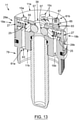
- the jounce adjustment component (19a) is positioned, shaped and sized with respect to the at least one active jounce fluid passage (15a) so that the default configuration of the jounce adjustment component (19a) corresponds to the fully-opened configuration of the jounce adjustment component (19a), as better shown in Figure 13 , for example.
- the jounce adjustment component (19a) may be positioned, shaped and sized with respect to the at least one active jounce fluid passage (15a) so that the default configuration of the jounce adjustment component (19a) corresponds to the fully-closed configuration of the jounce adjustment component (19a).
- the piston head (11) of the piston assembly (9) can comprise a jounce lodging passage (29a) being positioned, shaped and sized for receiving the jounce adjustment component (19a), the jounce lodging passage (29a) being further positioned, shaped and sized for fluidly intersecting the at least one active jounce fluid passage (15a).
- the at least one active jounce fluid passage (15a) can extend longitudinally along the piston head (11), and the jounce lodging passage (29a) can extend transversally with respect to the piston head (11).
- the jounce adjustment component (19a) can comprise a shouldering portion (31a) for resting against a corresponding abutment portion (33a) of the jounce lodging passage (29a) when the jounce adjustment component (19a) is in the default configuration.
- the jounce adjustment component (19a) is configured for adjustably moving in response to the input indicative of the positioning of the piston assembly (9) within the stroke distance (7) being received from said biasing assembly (21).
- the biasing assembly (21) can include a biasing component (35) provided with a jounce displacement-profile surface (35a) interacting with the jounce adjustment component (19a) for adjustably moving the jounce adjustment component (19a) with respect to the at least at least one active jounce fluid passage (15a) (ex. depending on a positioning of the jounce adjustment component (19a) with respect to the jounce displacement-profile surface (35a) of the biasing component (35), etc.).
- the chamber (13) containing the piston head (11) of the piston assembly (9) can be defined about a portion of the top mounting component (5), and the biasing component (35) with corresponding jounce displacement-profile surface (35a) can be mounted onto the top mounting component (5) and can be disposed along the chamber (13) of said top mounting component (5), as exemplified in the accompanying drawings.
- the biasing component (35) may include a profiled bar (37) being provided with the jounce displacement-profile surface (35a), and the profiled bar (37) may removably and pivotably mountable onto the top mounting component (5) via a corresponding attachment component (59), and may also be disposed centrally within the chamber (13) of the top mounting component (5), for example, although various other alternative disposition(s) and/or embodiment(s) are also be contemplated for the present system (1).
- the piston head (11) comprises a corresponding central hole (39) for receiving therethrough the profiled bar (37) of the biasing assembly (21) during a relative displacement of the bottom mounting component (5) with respect to the top mounting component (5).
- the piston head (11) may further comprise an interlocking component (41) disposed about the corresponding central hole (39) for interlocking with the profiled bar (37) during displacement of the profiled bar (37) through said corresponding central hole (39), and the interlocking component (41) may include a pin (41a) being removably mountable onto the piston head (11) via a fastener (43), the pin (41a) being positioned, shaped and sized for extending within the corresponding central hole (39) and for further fitting into a corresponding slot (41b) disposed about the profiled bar (37).
- the pin (41a) can be removably insertable into a corresponding receiving passage (85) defined about the piston head (11), for example, and the receiving passage (85) can be disposed transversally with respect to the piston head (11), and may extend from the central hole (39) of the piston head (11) to a side surface (11c) of the piston head (11), although various other alternative disposition(s) and/or embodiment(s), are also contemplated for the present system (1).
- the above-mentioned fastener (43) may be positioned, shaped and sized so that a top portion thereof is lodged within a corresponding recess (45) of the piston head (11) of the piston assembly (9), so as to prevent the top portion of the fastener (45) from exceeding beyond a top surface (11a) of said piston head (11).
- the position-relative damper assist system (1) can comprise a hollow separator component (47) being removably mountable onto the piston head (11), for use with an internal accumulator (49a), the hollow separator component (47) having an opened end operatively connectable to the corresponding central hole (39) of the piston head (11), and an opposite closed end for separating a fluid (51) of the internal accumulator (49a) from a fluid of the chamber (13).
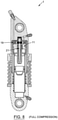
- the hollow separator component (47) is preferably made long enough for receiving the profiled bar (37) when the top and bottom mounting components (5,3) are operated in the "compression" mode (see Figure 8 , for example).
- the profiled bar (37) is preferably made long enough for interacting with the jounce adjustment component (19a) when the top and bottom mounting components (5,3) are operated in the "extension" mode (see Figure 9 , for example).
- the jounce adjustment component (19a) can include a spring-loaded plunger (53) having one end interacting with the jounce displacement-profile surface (35a) for moving in response to a corresponding contour of said jounce displacement-profile surface (35a).
- the jounce adjustment component (19a) can include a spring-loaded poppet (55) provided with an adjacent ball-bearing (57) interacting with the jounce displacement-profile surface (35a) for moving in response to a corresponding contour of said jounce displacement-profile surface (35a).
- the poppet (55) can also comprise a shouldering portion (31) for resting against a corresponding abutment portion (33), and a cross-sectional profile of the ball-bearing (57) is preferably made smaller than a cross-sectional profile of the poppet (55).
- the jounce displacement-profile surface (35a) is a curved jounce displacement-profile surface (35a) for providing at least two contact points to a corresponding component being operatively connected to the jounce adjustment component (19a).
- a jounce displacement-profile surface (35a) with only one contact point could also be used, and the fact that the jounce displacement-profile surface (35a) may be "curved" (and/or shaped otherwise, etc.) and provide a plurality of contact points (ex. two or more, etc.) is particularly advantageous for improved durability of the part(s), etc., when the adjustment assembly (19) and the biasing assembly (21) interact "mechanically", for example.
- the at least one active jounce fluid passage (15a) comprises a pair of active jounce fluid passages (15a) each for allowing fluid (17) of the chamber (13) to travel from one side of the chamber (13) to another side of the chamber via the piston head (11) of the piston assembly (9) during the compression mode
- the jounce adjustment component (19a) can be configured for adjustably varying an effective cross-sectional profile of both active jounce fluid passages (15a) in order to in turn vary a corresponding flow rate of fluid (17) passing through the pair of active jounce fluid passages (15a) during the compression mode.
- One end of the at least one active jounce fluid passage (15a) may be provided with a corresponding jounce shim assembly (61a) being configured for shimming fluid exiting said end of the at least one active jounce fluid passage (15a) during the compression mode.
- the jounce shim assembly (61a) can be further configured for preventing fluid from entering said end of the at least one active jounce fluid passage (15a) (for example, of each active jounce fluid passage (15a), etc.) during the "extension" mode.
- the jounce shim assembly (61a) may include a series of lamellae (63) being stackable onto one another, and the series of lamellae (63) may be nestable within a corresponding recess (65) defined about the piston head (11) of the piston assembly (9).
- the series of lamellae (63) can be secured onto the piston head (11) via at least one fastener (67), and the at least one fastener (67) is preferably positioned, shaped and sized so that a top portion thereof is prevented from exceeding beyond a top surface (11a) of the piston head (11) of the piston assembly (9).
- the at least one fastener (67) includes a pair of fasteners (67) configured for threaded engagement into the series of lamellae (63) and piston head (11), and the series of lamellae (63) may include a plurality of oblong lamellae (63) of different lengths, with a longest lamella (63) being positioned at a bottommost portion of the series of lamellae (63) and a shortest lamella (63) being positioned at an upper portion of the series of lamellae (63), each lamella (63) of the series of lamellae (63) being shorter than a preceding bottom lamella (63), for example.
- the at least one fluid passage (15) of the piston head (11) can also comprise at least one active rebound fluid passage (15b) for allowing fluid (17) of the chamber (13) to travel from one side of the chamber (13) to another side of the chamber (13) via the piston head (11) of the piston assembly (9) during the extension mode
- the adjustment assembly (19) can comprise a corresponding rebound adjustment component (19b) being configured for adjustably varying an effective cross-sectional profile of the at least one active rebound fluid passage (15b) in order to in turn vary a corresponding flow rate of fluid (17) passing through said at least one active rebound fluid passage (15b) during the extension mode.
- the rebound adjustment component (19b) can be a spring-loaded rebound adjustment component (19b), and the adjustment assembly (19) can thus comprise a corresponding spring (25) having one extremity operatively abutting against a given supporting component (27), and having another extremity operatively pushing against the rebound adjustment component (19b) for urging the rebound adjustment component (19b) into a given default configuration, the spring-loaded rebound adjustment component (19b) being adjustably operable via the biasing assembly (21) between variable opened and closed configurations, wherein in a fully-opened configuration, the rebound adjustment component (19b) is substantially clear from the at least one active rebound fluid passage (15b) in order to allow a maximal passage of fluid (17) through the at least one active rebound fluid passage (15b), and wherein in a fully-closed configuration, the rebound adjustment component (19b) substantially blocks the at least one active rebound fluid passage (15b) in order to allow a minimal passage of fluid (17) through the at least one active rebound fluid passage (15b).
- the rebound adjustment component (19b) is positioned, shaped and sized with respect to the at least one active rebound fluid passage (15b) so that the default configuration of the rebound adjustment component (19b) corresponds to the fully-opened configuration of the rebound adjustment component (19b), as better shown in Figure 13 , for example.
- the rebound adjustment component (19b) may be positioned, shaped and sized with respect to the at least one active rebound fluid passage (15b) so that the default configuration of the rebound adjustment component (19b) corresponds to the fully-closed configuration of the rebound adjustment component (19b).
- the piston head (11) of the piston assembly (9) can comprise a rebound lodging passage (29b) being positioned, shaped and sized for receiving the rebound adjustment component (19b), the rebound lodging passage (29b) being further positioned, shaped and sized for fluidly intersecting the at least one active rebound fluid passage (15b).
- the at least one active rebound fluid passage (15b) may extend longitudinally along the piston head (11), and whereas the rebound lodging passage (29b) may extend transversally with respect to the piston head (11).
- the rebound adjustment component (19b) can comprise a shouldering portion (31b) for resting against a corresponding abutment portion (33b) of the rebound lodging passage (29b) when the rebound adjustment component (19b) is in the default configuration.
- the rebound adjustment component (19b) is configured for adjustably moving in response to the input indicative of the positioning of the piston assembly (9) within the stroke distance (7) being received from the biasing assembly (21).
- the above-described single biasing component (35) (and/or a separate one) can be further provided with a rebound displacement-profile surface (35b) interacting with the rebound adjustment component (19b) for adjustably moving the rebound adjustment component (19b) with respect to the at least at least one active rebound fluid passage (15b) (ex. depending on a positioning of the rebound adjustment component (19b) with respect to the rebound displacement-profile surface (35b) of the biasing component (35), etc.).
- the biasing component (35) with corresponding rebound displacement-profile surface (35b) can be mounted onto the top mounting component (7) and can be disposed along the chamber of said top mounting component (7).
- the profiled bar (37) may be further provided with the rebound displacement-profile surface (35b), and is preferably made long enough for interacting with the rebound adjustment component (19b) when the top and bottom mounting components (5,3) are operated in the "extension" mode (see Figure 9 , for example).
- the rebound adjustment component (19b) can include a spring-loaded plunger (53) having one end interacting with the rebound displacement-profile surface (35b) for moving in response to a corresponding contour of said rebound displacement-profile surface (35b).
- the rebound adjustment component (19b) can include a spring-loaded poppet (55) provided with an adjacent ball-bearing (57) interacting with the rebound displacement-profile surface (35b) for moving in response to a corresponding contour of said rebound displacement-profile surface (35b).
- This poppet (55) can also comprise a shouldering portion (31) for resting against a corresponding abutment portion (33), and a cross-sectional profile of the ball-bearing (57) is preferably made smaller than a cross-sectional profile of the poppet (55).
- the rebound displacement-profile surface (35b) is a curved rebound displacement-profile surface (35b) for providing at least two contact points to a corresponding component being operatively connected to the rebound adjustment component (19b).
- the rebound displacement-profile surface (35b) may be provided with a single contact point, as previously discussed when referring to the "jounce" counterpart.
- the at least one active rebound fluid passage (15b) comprises a pair of active rebound fluid passages (15b) each for allowing fluid (17) of the chamber (13) to travel from one side of the chamber (13) to another side of the chamber (13) via the piston head (11) of the piston assembly (9) during the extension mode
- the rebound adjustment component (19b) can be configured for adjustably varying an effective cross-sectional profile of both active rebound fluid passages (15b) in order to in turn vary a corresponding flow rate of fluid (17) passing through the pair of active rebound fluid passages (15b) during the extension mode.
- One end of the at least one active rebound fluid passage (15b) may be provided with a corresponding rebound shim assembly (61b) being configured for shimming fluid (17) exiting said end of the at least one active rebound fluid passage (15b) during the "extension" mode.
- the rebound shim assembly (61b) can be further configured for preventing fluid (17) from entering said end of the at least one active rebound fluid passage (15b) (for example, of each active rebound fluid passage (15b), etc.) during the "compression" mode.
- the rebound shim assembly (61b) can have components and features similar to that of the jounce shim assembly (61a).
- such a directional control and/or flow of the fluid could be achieved via a "ball bearing” and a machined “seat", for example, in which flow can either travel around the ball bearing through the piston head, or the ball bearing becomes seated, blocking all flow through the desired passage (15,15a,15b), etc., as can be easily understood by a person skilled in the art.
- the at least one active jounce fluid passage (15a) and corresponding jounce adjustment component (19a) can be disposed on one side of the piston head (11), and the at least one active rebound fluid passage (15b) and corresponding rebound adjustment component (19b) can be disposed on another opposite side of the piston head (11), as better shown in Figure 13 , for example.
- the jounce lodging passage (29a) and the rebound lodging passage (29b) can be fluidly connected to one another, and the jounce lodging passage (29a) and the rebound lodging passage (29b) can be further fluidly connected to the corresponding central hole (39) of the piston head (11), as also exemplified in Figure 13 .
- the at least one fluid passage (15) of the piston head (11) can comprise at least one passive fluid passage (15c) for allowing fluid (17) of the chamber (13) to travel from one side of the chamber (13) to another side of the chamber via the piston head (11) of the piston assembly (9) during either one (and preferably, both) of the compression and extension modes.
- the at least one fluid passage (15) of the piston head (11) comprises a pair of passive fluid passages (15c) for allowing fluid (17) of the chamber (13) to travel from one side of the chamber (13) to another side of the chamber (13) via the piston head (11) of the piston assembly (9) during either one (and preferably, both) of the compression and extension modes.
- the at least one fluid passage (15) of the piston head (11) includes at least one fluid passage (15) being internal to the piston head (11) of the piston assembly (9), as exemplified in the accompanying figures, but according to alternative possible embodiments of the present system (1), the at least one fluid passage (15) of the piston head (11) can also and/or alternatively include at least one fluid passage (15) being external to the piston head (11) of the piston assembly (9).
- At least one of the top and bottom mounting components (5,3) is provided with an eyelet (69), and optionally, the top and bottom mounting components (5,3) are each provided with a corresponding eyelet (69), and the stroke distance (7) of the top and bottom mounting components (5,3) corresponds to an "eyelet-to-eyelet” distance.
- each eyelet (69) may also be provided with a corresponding bearing (71).
- the position-relative damper assist system (1) can comprise an outer-seal end cap (73) for sealingly closing an interface between the top and bottom mounting components (5,3), the chamber (13) can be operatively connected to at least one corresponding port (75) selected from the group consisting of bleed port (75a) and fill port (75b).
- the present system (1) may be used with and/or for a variety of different piston assemblies (9), but according to one possible embodiment, the piston assembly (9) can comprise a piston rod (77) operatively extending between the bottom mounting component (3) of the position-relative damper assist system (1) and the piston head (11) of the piston assembly (9), with the piston head (11) being removably mountable onto the piston rod (77), if so desired via threading, for example, and the piston head (11) may also comprise a mounting collar (79) extending from a bottom surface (11b) of the piston head (11), the mounting collar (79) being configured for securing onto the piston rod (77).
- the piston assembly (9) can comprise a piston rod (77) operatively extending between the bottom mounting component (3) of the position-relative damper assist system (1) and the piston head (11) of the piston assembly (9), with the piston head (11) being removably mountable onto the piston rod (77), if so desired via threading, for example, and the piston head (11) may also comprise a
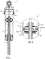
- the piston rod (77) can comprise a hollow section being provided an internal accumulator (49a) having a floating piston head (81), and the floating piston head (81) may have a cross-sectional shape being complementary to that of an adjacent separator component (47), for allowing the floating piston head (81) to travel within a greater range for a same given length of the internal accumulator (49a), as better shown in Figure 5, for example.
- Figures 1 and 2 show how the position-relative damper assist system (1) can comprise and/or be used with an external accumulator (49b) configured for cooperating with the piston assembly (9).
- the position-relative damper assist system (1) can comprise a shock-absorbing spring (83) interacting between the bottom and top mounting components (3,5), and the shock-absorbing spring (83) can be a coil spring having one end operatively secured to the top mounting component (5) (via a "spring seat” and/or any other suitable component, for example), and another end operatively secured to the bottom mounting component (3) (via a "retainer” and/or any other suitable component, for example).
- a kit with components for assembling a fully-assembled and fully-operational position-relative damper assist system (1) such as the one described and/or alluded to in the present patent specification, and accompanying drawings.
- a vehicle provided with such as position-relative damper assist system (1).
- the piston head (11) having one and/or several of the various components and/or features described and/or alluded to in the present patent specification, and accompanying drawings. According to yet another possible aspect of the present invention, there is also provided a kit with components for assembling such a piston head (11).
- the damping of the jounce orifice is achieved through the jounce profile tracking assembly (19a,53), which tracks/follows the contours of the damping profile rod - jounce (35a) located in the piston rod (77).
- the damping profile rod (35a,35b) is fixed at the rod attachment point (59), which allows it to rotate freely within the piston rod 77).
- the jounce profile tracking assembly (19a,53) follows the contours of the profile, opening/restricting the flow through the jounce orifice(s) (15a) as required.
- the profile details are selected to provide specific position-relative damping characteristics.
- the jounce profile tracking assembly (19a,53) can be preloaded in a way to ensure proper contact with the damping profile rod (35a,35b), naturally allowing full flow through the jounce orifices (15a) when the contour is smallest and greatest restriction when over profile peaks.
- the preload of the tracking assemblies (19a,53) can be achieved but is not limited to compression springs, wave springs, etc.
- the profile tracking assembly (19b,53) design details can vary in shape, size and quantity. In some instances, the design may be required to support a threshold flow rate/pressure in which some jounce/rebound orifices are not position specific.
- the motion of a single profile tracking assembly could adjust damping within numerous damping orifices, jounce or rebound, depending on functional requirements.
- the damping profile rod (35a,35b) can be adjusted to allow easy modification of damping characteristics relative to position. This could be achieved through an adjustment screw located on the bottom of the piston rod (77), for example.
- the jounce and rebound profiles can be application specific, and in some instances, may mimic one another.
- the cross-sectional design of the damping profile rod (35a,35b,37) could be a variety of shapes such as an 'X', square, or any other suitable and/or functionally equivalent shape, etc.
- "jounce” and “rebound” damping can be controlled through the inclusion of jounce (61a) and rebound (61b) shim stacks.
- the stacks limit flow in their respective directions of travel, effectively functioning as directional flow valves.
- the size of the orifices is influenced by the tracking profile assembly.
- the tracking profile assembly can be made as one device with profile on both side as shown on surface (35b) and surface (35a).
- the tracking profile assembly can also be made of two separate tracking profile assembly.
- An adjustment mechanism made of one adjustment knob or two adjustment knobs could also be used to pre-set the static position of the position damping. The adjustment mechanism could also be used to operate the knobs, etc.
- the present invention is a substantial improvement over the damping systems of the prior art in that, by virtue of its design and components, as briefly explained herein, the present system enables to overcome or at least minimize some of the known drawbacks associated with conventional systems, providing for a simpler, easier, faster, more accurate, more effective, more functional, more reliable and/or more versatile position-relative damper assist system than what is possible with other conventional systems.
- the present position-relative damper assist system and corresponding parts are preferably made of substantially rigid materials, such as metallic materials, hardened polymers, composite materials, polymeric materials (ex. seals, etc.), and/or the like, so as to ensure a proper operation thereof depending on the particular applications for which the position-relative damper assist system is intended and the different parameters (forces, moments, etc.) in cause, as apparent to a person skilled in the art.
Landscapes
- Engineering & Computer Science (AREA)
- General Engineering & Computer Science (AREA)
- Mechanical Engineering (AREA)
- Fluid-Damping Devices (AREA)
- Vehicle Body Suspensions (AREA)
Claims (15)
- Positionsbezogenes Dämpferunterstützungssystem (1) zur Verwendung mit einem Fahrzeug, wobei das positionsbezogene Dämpferunterstützungssystem (1) Folgendes umfasst:obere und untere Montagekomponenten (5, 3), die miteinander zusammenarbeiten, um eine entsprechende Hubdistanz (7) zwischen sich zu definieren, und mit Bezug aufeinander zwischen Kompressions- und Extensionsmodus entlang der Hubdistanz betätigt werden können, wobei die obere Montagekomponente (5) im Betrieb mit einem Rahmen des Fahrzeugs verbunden sein kann, und wobei die untere Montagekomponente (5) im Betrieb mit einer Trägerkomponente des Fahrzeugs verbunden werden kann;eine Kolbenanordnung (9), die im Betrieb zwischen der oberen und unteren Montagekomponente (5, 3) angeordnet ist, wobei die Kolbenanordnung (9) einen Kolbenkopf (11) aufweist, der innerhalb einer Kammer (13) verschoben werden kann, die um einen Abschnitt einer der oberen und unteren Montagekomponente (5, 3) definiert ist, wobei der Kolbenkopf (11) mit mindestens einem Fluiddurchgang (15) ausgestattet ist, um zu ermöglichen, dass Fluid (17) der Kammer (13) von einer Seite der Kammer (13) zu einer anderen Seite der Kammer (13) über den Kolbenkopf (11) der Kolbenanordnung (9) strömt, um einen entsprechenden Dämpfungseffekt bereitzustellen;eine Einstellanordnung (19), die mit dem Kolbenkopf (11) der Kolbenanordnung (9) zusammenarbeitet, um einstellbar ein effektives Querschnittsprofil des mindestens einen Fluiddurchgangs (15) zu variieren, um seinerseits eine entsprechende Durchflussrate von Fluid (17) zu variieren, das durch den mindestens einen Fluiddurchgang (15) verläuft, und seinerseits den sich ergebenden Dämpfungseffekt zu variieren; undeine Vorspannanordnung (21), die mit der Einstellanordnung (19) zusammenarbeitet, um selektiv eine Konfiguration der Einstellanordnung (19) in Reaktion auf einen bestimmten Input zu variieren, der die Positionierung der Kolbenanordnung (9) innerhalb der Hubdistanz (7) anzeigt, um den sich ergebenden Dämpfungseffekt in Reaktion auf ein entsprechendes Verschiebungsprofil (23) zu variieren, das von der Vorspannungsanordnung (21) bereitgestellt ist,dadurch gekennzeichnet, dass die Einstellanordnung (19) im Inneren des Kolbenkopfs (11) enthalten ist, und konfiguriert, um einstellbar das effektive Querschnittsprofil des mindestens einen Fluiddurchgangs (15) im inneren des Kolbenkopfs (19) zu variieren.
- Positionsbezogenes Dämpferunterstützungssystem (1) nach Anspruch 1, wobei der mindestens eine Fluiddurchgang (15) des Kolbenkopfs (11) mindestens einen aktiven Aufschlag-Fluiddurchgang (15a) umfasst, um zu ermöglichen, dass Fluid (17) der Kammer (13) von einer Seite der Kammer (13) zu einer anderen Seite der Kammer über den Kolbenkopf (11) der Kolbenanordnung (9) während des Kompressionsmodus strömt, und wobei die Einstellanordnung (19) eine Aufschlag-Einstellkomponente (19a) umfasst, die konfiguriert ist, um einstellbar ein effektives Querschnittsprofil des mindestens einen aktiven Aufschlag-Fluiddurchgangs (15a) zu variieren, um seinerseits eine entsprechende Durchflussrate von Fluid (17) zu variieren, das durch den mindestens einen aktiven Aufschlag-Fluiddurchgang (15a) während des Kompressionsmodus strömt.
- Positionsbezogenes Dämpferunterstützungssystem (1) nach Anspruch 2, wobei eine Aufschlag-Einstellkomponente (19a) eine federgeladene Aufschlag-Einstellkomponente (19a) ist, und wobei die Einstellanordnung (19) somit eine entsprechende Feder (25) mit einem Ende umfasst, das im Betrieb gegen eine bestimmte Trägerkomponente (27) anschlägt, und ein anderes Ende aufweist, das im Betrieb gegen die Aufschlag-Einstellkomponente (19a) schiebt, um die Aufschlag-Einstellkomponente (19a) in eine bestimmte Standardkonfiguration zu zwingen, wobei die federgeladene Aufschlag-Einstellkomponente (19a) einstellbar über die Vorspannanordnung (21) zwischen der variablen geöffneten und geschlossenen Konfiguration betätigt werden kann, wobei in einer vollständig geöffneten Konfiguration die Aufschlag-Einstellkomponente (19a) im Wesentlichen frei von dem mindestens einen aktiven Aufschlag-Fluiddurchgang (15a) ist, um einen maximalen Durchgang von Fluid (17) durch den mindestens einen aktiven Aufschlag-Fluiddurchgang (15a) zu ermöglichen, und wobei in einer vollständig geschlossenen Konfiguration die Aufschlag-Einstellkomponente (19a) im Wesentlichen den mindestens einen aktiven Aufschlag-Fluiddurchgang (15a) blockiert, um einen minimalen Durchgang von Fluid (17) durch den mindestens einen aktiven Aufschlag-Fluiddurchgang (15a) zu ermöglichten;wobei die Aufschlag-Einstellkomponente (19a) mit Bezug auf den mindestens einen aktiven Aufschlag-Fluiddurchgang (15a) derart positioniert, geformt und abgemessen ist, dass die Standardkonfiguration der Aufschlag-Einstellkomponente (19a) der vollständig geöffneten Konfiguration der Aufschlag-Einstellkomponente (19a) oder der vollständig geschlossenen Konfiguration der Aufschlag-Einstellkomponente (19a) entspricht;wobei der Kolbenkopf (11) der Kolbenanordnung (9) einen Aufschlag-Aufnahmedurchgang (29a) umfasst, der positioniert, geformt und abgemessen ist, um die Aufschlag-Einstellkomponente (19a) zu empfangen, wobei der Aufschlag-Aufnahmedurchgang (29a) weiter positioniert, geformt und abgemessen ist, um fluidisch den mindestens einen aktiven Aufschlag-Fluiddurchgang (15a) zu kreuzen;wobei sich der mindestens eine aktive Aufschlag-Fluiddurchgang (15a) der Länge nach entlang dem Kolbenkopf (11) erstreckt, und wobei sich der Aufschlag-Aufnahmedurchgang (29a) quer mit Bezug auf den Kolbenkopf (11) erstreckt;wobei die Aufschlag-Einstellkomponente (19a) einen vorspringenden Abschnitt (31a) umfasst, um gegen einen entsprechenden Anschlagabschnitt (33a) des Aufschlag-Aufnahmedurchgangs (29a) zu liegen, wenn sich die Aufschlag-Einstellkomponente (19a) in der Standardkonfiguration befindet;wobei die Aufschlag-Einstellkomponente (19a) konfiguriert ist, um sich einstellbar in Reaktion auf den Input zu bewegen, die die Positionierung der Kolbenanordnung (9) innerhalb der Hubdistanz (7) anzeigt, die von der Vorspannungsanordnung (21) empfangen wird;wobei die Vorspannungsanordnung (21) eine Vorspannungskomponente (35) beinhaltet, die mit einer Aufschlag-Verschiebungsprofilfläche (35a) ausgestattet ist, die mit der Aufschlag-Einstellkomponente (19a) interagiert, um einstellbar die Aufschlag-Einstellkomponente (19a) mit Bezug auf den mindestens einen aktiven Aufschlag-Fluiddurchgang (15a) zu bewegen;wobei die Kammer (13), die den Kolbenkopf (11) der Kolbenanordnung (9) enthält, um einen Abschnitt der oberen Montagekomponente (5) definiert ist, und wobei die Vorspannungskomponente (35) mit einer entsprechenden Aufschlag-Verschiebungsprofilfläche (35a) auf die obere Montagekomponente (5) montiert ist und entlang der Kammer (13) der oberen Montagekomponente (5) angeordnet ist;wobei die Vorspannungskomponente (35) eine profilierte Stange (37) beinhaltet, die mit einer Aufschlag-Verschiebungsprofilfläche (35a) ausgestattet ist;wobei die profilierte Stange (37) entfernbar und schwenkbar auf die obere Montagekomponente (5) über eine Befestigungskomponente (59) montiert werden kann;wobei die profilierte Stange (37) zentral innerhalb der Kammer (13) der oberen Montagekomponente (5) angeordnet ist;wobei der Kolbenkopf (11) ein entsprechendes zentrales Loch (39) umfasst, um dadurch die profilierte Stange (37) der Vorspannungsanordnung (21) während einer relativen Verschiebung der unteren Montagekomponente (3) mit Bezug auf die obere Montagekomponente (5) zu empfangen;wobei der Kolbenkopf (11) weiter eine Verriegelungskomponente (41) umfasst, die um das entsprechende zentrale Loch (39) angeordnet ist, um mit der profilierten Stange (37) während der Verschiebung der profilierten Stange (37) durch das entsprechende zentrale Loch (39) zu verriegeln;wobei die Verriegelungskomponente (41) einen Stift (41a) beinhaltet, der entfernbar auf den Kolbenkopf (11) über eine Befestigungsvorrichtung (43) montiert werden kann, wobei der Stift (41a) positioniert, geformt und abgemessen ist, um sich innerhalb des entsprechenden zentralen Lochs (39) zu erstrecken, und um weiter in einen entsprechenden Schlitz (41b) zu passen, der um die profilierte Stange (37) angeordnet ist;wobei der Stift (41a) entfernbar in einen entsprechenden Empfangsdurchgang (85) eingeführt werden kann, der um den Kolbenkopf (11) definiert ist;wobei der Empfangsdurchgang (85) quer mit Bezug auf den Kolbenkopf (11) angeordnet ist;wobei sich der Empfangsdurchgang vom zentralen Loch (39) des Kolbenkopfs (11) zu einer Seitenfläche (11c) des Kolbenkopfs (11) erstreckt;wobei die Befestigungsvorrichtung (43) derart positioniert, geformt und abgemessen ist, dass ein oberer Abschnitt davon innerhalb einer entsprechenden Aussparung (45) des Kolbenkopfs (11) der Kolbenanordnung (9) aufgenommen ist, um zu verhindern, dass der obere Abschnitt der Befestigungsvorrichtung (43) eine obere Fläche (11a) des Kolbenkopfs (11) überragt;wobei das positionsbezogene Dämpferunterstützungssystem (1) eine hohle Trennkomponente (47) umfasst, die entfernbar auf den Kolbenkopf (11) montiert werden kann, um mit einem internen Akkumulator (49a) verwendet zu werden, wobei die hohle Trennkomponente (47) ein geöffnetes Ende aufweist, das im Betrieb mit dem entsprechenden zentralen Loch (39) des Kolbenkopfs (11) verbunden werden kann, und ein gegenüberliegendes geschlossenes Ende, um ein Fluid (51) des internen Akkumulators (49a) vom Fluid (17) der Kammer (13) zu trennen;wobei die hohle Trennkomponente (47) lang genug ist, um die profilierte Stange (37) zu empfangen, wenn die obere und untere Montagekomponente (5, 3), im Kompressionsmodus betrieben werden;wobei die profilierte Stange (37) lang genug ist, um mit der Aufschlag-Einstellkomponente (19a) zu interagieren, wenn die obere und untere Montagekomponente (5, 3) im Extensionsmodus betrieben werden;wobei die Aufschlag-Einstellkomponente (19a) einen federgespannten Stößel (53) beinhaltet, der ein Ende aufweist, das mit der Aufschlag-Verschiebungsprofilfläche (35a) interagiert, um sich in Reaktion auf einen entsprechenden Umfang der Aufschlag-Verschiebungsprofilfläche (35a) zu bewegen;wobei die Aufschlag-Einstellkomponente (19a) ein federgespanntes Tellerventil (55) beinhaltet, das mit einem benachbarten Kugellager (57) ausgestattet ist, das mit einer Aufschlag-Verschiebungsprofilfläche (35a) interagiert, um sich in Reaktion auf einen entsprechenden Umfang der Aufschlag-Verschiebungsprofilfläche (35a) zu bewegen;wobei das Tellerventil (55) einen vorspringenden Abschnitt (31) umfasst, um gegen einen entsprechenden Anschlagabschnitt (33) zu liegen;wobei ein Querschnittsprofil des Kugellagers (57) kleiner als ein Querschnittsprofil des Tellerventils (55) ist;wobei die Aufschlag-Verschiebungsprofilfläche (35a) eine gekrümmte Aufschlag-Verschiebungsprofilfläche (35a) ist, um mindesten zwei Kontaktpunkte mit einer entsprechenden Komponente bereitzustellen, die im Betrieb mit der Aufschlag-Einstellkomponente (19a) verbunden ist;wobei der mindestens eine aktive Aufschlag-Fluiddurchgang (15a) mindestens ein Paar aktiver Aufschlag-Fluiddurchgänge (15a) umfasst, wobei jeder ermöglicht, dass Fluid (17) der Kammer (13) von einer Seite der Kammer (13) zu einer anderen Seite der Kammer über den Kolbenkopf (11) der Kolbenanordnung (9) während des Kompressionsmodus strömt, und wobei die Aufschlag-Einstellkomponente (19a) konfiguriert ist, um einstellbar ein effektives Querschnittsprofil beider aktiver Aufschlag-Fluiddurchgänge (15a) zu variieren, um seinerseits eine entsprechende Durchflussrate von Fluid (17) zu variieren, das durch das Paar von aktiven Aufschlag-Fluiddurchgängen (15a) während des Kompressionsmodus strömt;wobei ein Ende des mindestens einen aktiven Aufschlag-Fluiddurchgangs (15a) mit einer entsprechenden Aufschlag-Unterleganordnung (61a) ausgestattet ist, die konfiguriert ist, um Fluid zu unterlegen, das aus dem Ende des mindestens einen aktiven Aufschlag-Fluiddurchgangs (15a) während des Kompressionsmodus strömt;wobei die Aufschlag-Unterleganordnung (61a) weiter konfiguriert ist, um zu verhindern, dass Fluid in das Ende des mindestens einen aktiven Aufschlag-Fluiddurchgangs (15a) während des Extensionsmodus eintritt;wobei die Aufschlag-Unterleganordnung (61a) eine Reihe von Lamellen (63) beinhaltet, die aufeinander gestapelt werden können;wobei die Reihe von Lamellen (63) in einer entsprechenden Aussparung (65) geschachtelt werden kann, die um den Kolbenkopf (11) der Kolbenanordnung (9) definiert ist;wobei die Reihe von Lamellen (63) auf den Kolbenkopf (11) über mindestens eine Befestigungsvorrichtung (67) gesichert werden kann;wobei die mindestens eine Befestigungsvorrichtung (67) derart positioniert, geformt und abgemessen ist, dass verhindert wird, dass ein oberer Abschnitt davon über eine obere Fläche (11a) des Kolbenkopfs (11) der Kolbenanordnung (9) vorsteht;wobei die mindestens eine Befestigungsvorrichtung (67) ein Paar von Befestigungsvorrichtungen (67) beinhaltet, die konfiguriert sind, um in die Reihe von Lamellen (63) und den Kolbenkopf (11) eingeschraubt zu werden;wobei die Reihe von Lamellen (63) eine Vielzahl von länglichen Lamellen (63) mit verschiedenen Längen beinhaltet, wobei eine längste Lamelle (63) an einem untersten Abschnitt der Reihe von Lamellen (63) positioniert ist, und wobei eine kürzeste Lamelle (63) an einem oberen Abschnitt der Reihe von Lamellen (63) positioniert ist; und/oderwobei jede Lamelle (63) der Reihe von Lamellen (63) kürzer als eine vorhergehende untere Lamelle (63) ist.
- Positionsbezogenes Dämpferunterstützungssystem (1) nach einem der Ansprüche 1 - 3, wobei der mindestens eine Fluiddurchgang (15) des Kolbenkopfs (11) mindestens einen aktiven Rückschlag-Fluiddurchgang (15b) umfasst, um zu ermöglichen, dass Fluid (17) der Kammer (13) von einer Seite der Kammer (13) zu einer anderen Seite der Kammer (13) über den Kolbenkopf (11) der Kolbenanordnung (9) während des Extensionsmodus strömt, und wobei die Einstellanordnung (19) eine Rückschlag-Einstellkomponente (19b) umfasst, die konfiguriert ist, um einstellbar ein effektives Querschnittsprofil des mindestens einen aktiven Rückschlag-Fluiddurchgangs (15b) zu variieren, um seinerseits eine entsprechende Durchflussrate von Fluid (17) zu variieren, das durch den mindestens einen aktiven Rückschlag-Fluiddurchgang (15b) während des Extensionsmodus strömt.
- Positionsbezogenes Dämpferunterstützungssystem (1) nach Anspruch 4, wobei die Rückschlag-Einstellkomponente (19b) eine federgeladene Rückschlag-Einstellkomponente (19b) ist, und wobei die Einstellanordnung (19) somit eine entsprechende Feder (25) mit einem Ende umfasst, das im Betrieb gegen eine bestimmte Trägerkomponente (27) anschlägt, und einem anderen Ende, das im Betrieb gegen die Rückschlag-Einstellkomponente (19b) schiebt, um die Rückschlag-Einstellkomponente (19b) in eine bestimmte Standardkonfiguration zu zwingen, wobei die federgeladene Rückschlag-Einstellkomponente (19b) einstellbar über die Vorspannanordnung (21) zwischen der variablen geöffneten und geschlossenen Konfiguration betätigt werden kann, wobei in einer vollständig geöffneten Konfiguration die Rückschlag-Einstellkomponente (19b) im Wesentlichen frei vom mindestens einem aktiven Rückschlag-Fluiddurchgang (15b) ist, um einen maximalen Durchgang von Fluid (17) durch den mindestens einen aktiven Rückschlag-Fluiddurchgang (15b) zu ermöglichen, und wobei in einer vollständig geschlossenen Konfiguration die Rückschlag-Einstellkomponente (19b) im Wesentlichen den mindestens einen aktiven Aufschlag-Fluiddurchgang (15b) blockiert, um einen minimalen Durchgang von Fluid (17) durch den mindestens einen aktiven Rückschlag-Fluiddurchgang (15b) zu ermöglichen;wobei die Rückschlag-Einstellkomponente (19b) mit Bezug auf den mindestens einen aktiven Rückschlag-Fluiddurchgang (15b) derart positioniert, geformt und abgemessen ist, dass die Standardkonfiguration der Rückschlag-Einstellkomponente (19b) der vollständig geöffneten Konfiguration der Rückschlag-Einstellkomponente (19b) oder der vollständig geschlossenen Konfiguration der Rückschlag-Einstellkomponente (19b) entspricht;wobei der Kolbenkopf (11) der Kolbenanordnung (9) einen Rückschlag-Aufnahmedurchgang (29b) umfasst, der positioniert, geformt und abgemessen ist, um die Rückschlag-Einstellkomponente (19b) zu empfangen, wobei der Rückschlag-Aufnahmedurchgang (29b) weiter positioniert, geformt und abgemessen ist, um fluidisch den mindestens einen aktiven Rückschlag-Fluiddurchgang (15b) zu kreuzen;wobei sich der mindestens eine aktive Rückschlag-Fluiddurchgang (15b) der Länge nach entlang dem Kolbenkopf (11) erstreckt, und wobei sich der Rückschlag-Aufnahmedurchgang (29b) quer mit Bezug auf den Kolbenkopf (11) erstreckt;wobei die Rückschlag-Einstellkomponente (19b) einen vorspringenden Abschnitt (31b) umfasst, um gegen einen entsprechenden Anschlagabschnitt (33b) des Rückschlag-Aufnahmedurchgangs (29b) zu liegen, wenn sich die Rückschlag-Einstellkomponente (19b) in der Standardkonfiguration befindet;wobei die Rückschlag-Einstellkomponente (19b) konfiguriert ist, um sich einstellbar in Reaktion auf den Input zu bewegen, der die Positionierung der Kolbenanordnung (9) innerhalb der Hubdistanz (7) anzeigt, die von der Vorspannungsanordnung (21) empfangen wird;wobei die Vorspannungskomponente (35) weiter mit einer Rückschlag-Verschiebungsprofilfläche (35b) ausgestattet ist, die mit der Aufschlag-Einstellkomponente (19b) interagiert, um einstellbar die Anschlag-Einstellkomponente (19b) mit Bezug auf den mindestens einen aktiven Rückschlag-Fluiddurchgang (15b) zu bewegen;wobei die Vorspannungskomponente (35) mit einer entsprechenden Rückschlag-Verschiebungsprofilfläche (35b) auf die obere Montagekomponente (5) montiert ist und entlang der Kammer der oberen Montagekomponente (5) angeordnet ist;wobei die profilierte Stange (37) weiter mit der Rückschlag-Verschiebungsprofilfläche (35b) ausgestattet ist;wobei die profilierte Stange (37) lang genug ist, um mit der Anschlag-Einstellkomponente (19b) zu interagieren, wenn die obere und untere Montagekomponente (5, 3) im Extensionsmodus betrieben werden;wobei die Rückschlag-Einstellkomponente (19b) einen federgespannten Stößel (53) beinhaltet, der ein Ende aufweist, das mit der Rückschlag-Verschiebungsprofilfläche (35b) interagiert, um sich in Reaktion auf einen entsprechenden Umfang der Rückschlag-Verschiebungsprofilfläche (35b) zu bewegen;wobei die Rückschlag-Einstellkomponente (19b) ein federgespanntes Tellerventil (55) beinhaltet, das mit einem benachbarten Kugellager (57) ausgestattet ist, das mit der Rückschlag-Verschiebungsprofilfläche (35b) interagiert, um sich in Reaktion auf einen entsprechenden Umfang der Rückschlag-Verschiebungsprofilfläche (35b) zu bewegen;wobei das Tellerventil (55) einen vorspringenden Abschnitt (31) umfasst, um gegen einen entsprechenden Anschlagabschnitt (33) zu liegen;wobei ein Querschnittsprofil des Kugellagers (57) kleiner als ein Querschnittsprofil des Tellerventils (55) ist;wobei die Rückschlag-Verschiebungsprofilfläche (35b) eine gekrümmte Rückschlag-Verschiebungsprofilfläche (35b) ist, um mindestens zwei Kontaktpunkte mit einer entsprechenden Komponente bereitzustellen, die im Betrieb mit der Rückschlag-Einstellkomponente (19b) verbunden ist;wobei der mindestens eine aktive Rückschlag-Fluiddurchgang (15b) ein Paar aktiver Rückschlag-Fluiddurchgänge (15b) umfasst, wobei jeder ermöglicht, dass Fluid (17) der Kammer (13) von einer Seite der Kammer (13) zu einer anderen Seite der Kammer (13) über den Kolbenkopf (11) der Kolbenanordnung (9) während des Extensionsmodus strömt, und wobei die Rückschlag-Einstellkomponente (19b) konfiguriert ist, um einstellbar ein effektives Querschnittsprofil beider aktiver Rückschlag-Fluiddurchgänge (15b) zu variieren, um seinerseits eine entsprechende Durchflussrate von Fluid (17) zu variieren, die durch das Paar von aktiven Rückschlag-Fluiddurchgängen (15b) während des Extensionsmodus strömt;wobei ein Ende des mindestens einen aktiven Rückschlag-Fluiddurchgangs (15b) mit einer entsprechenden Rückschlag-Unterleganordnung (61b) ausgestattet ist, die konfiguriert ist, um Fluid (17) zu unterlegen, das vom Ende des mindestens einen aktiven Aufschlag-Fluiddurchgangs (15b) während des Extensionsmodus austritt;wobei die Rückschlag-Unterleganordnung (61b) weiter konfiguriert ist, um zu verhindern, dass Fluid (17) in das Ende des mindestens einen aktiven Anschlag-Fluiddurchgangs (15b) während des Kompressionsmodus eintritt;wobei die Rückschlag-Unterleganordnung (61b) eine Reihe von Lamellen (63) beinhaltet, die aufeinander gestapelt werden können;wobei die Reihe von Lamellen (63) in einer entsprechenden Aussparung (65) geschachtelt werden kann, die um den Kolbenkopf (11) der Kolbenanordnung (9) definiert ist;wobei die Reihe von Lamellen (63) auf den Kolbenkopf (11) über mindestens eine Befestigungsvorrichtung (67) gesichert werden kann;wobei die mindestens eine Befestigungsvorrichtung (67) derart positioniert, geformt und abgemessen ist, dass verhindert wird, dass ein oberer Abschnitt davon über eine obere Fläche (11a) des Kolbenkopfs (11) der Kolbenanordnung (9) vorsteht;wobei die mindestens eine Befestigungsvorrichtung (67) ein Paar von Befestigungsvorrichtungen (67) beinhaltet, die konfiguriert sind, um in die Reihe von Lamellen (63) und den Kolbenkopf (11) eingeschraubt zu werden;wobei die Reihe von Lamellen (63) eine Vielzahl von länglichen Lamellen (63) mit verschiedenen Längen beinhaltet, wobei eine längste Lamelle (63) an einem untersten Abschnitt der Reihe von Lamellen (63) positioniert ist, und wobei eine kürzeste Lamelle (63) an einem oberen Abschnitt der Reihe von Lamellen (63) positioniert ist;wobei jede Lamelle (63) der Reihe von Lamellen (63) kürzer als eine vorhergehende untere Lamelle (63) ist;wobei der mindestens eine aktive Anschlag-Fluiddurchgang (15a) und die entsprechende Anschlag-Einstellkomponente (19a) an einer Seite des Kolbenkopfs (11) angeordnet sind, und wobei der mindestens eine aktive Rückschlag-Fluiddurchgang (15b) und die entsprechende Rückschlag-Einstellkomponente (19b) an einer anderen gegenüberliegenden Seite des Kolbenkopfs (11) angeordnet sind;wobei der Anschlag-Aufnahmedurchgang (29a) und der Rückschlag-Aufnahmedurchgang (29b) fluidisch miteinander verbunden sind; und/oderwobei der Anschlag-Aufnahmedurchgang (29a) und der Rückschlag-Aufnahmedurchgang (29b) weiter mit dem entsprechenden zentralen Loch (39) des Kolbenkopfs (11) fluidisch verbunden sind.
- Positionsbezogenes Dämpferunterstützungssystem (1) nach einem der Ansprüche 1 - 5, wobei der mindestens eine Fluiddurchgang (15) des Kolbenkopfs (11) mindestens einen passiven Fluiddurchgang (15c) umfasst, um zu ermöglichen, dass Fluid (17) der Kammer (13) von einer Seite der Kammer (13) zu einer anderen Seite der Kammer über den Kolbenkopf (11) der Kolbenanordnung (9) während eines des Kompressions- und Extensionsmodus strömt;wobei der mindestens eine Fluiddurchgang (15) des Kolbenkopfs (11) ein Paar passiver Fluiddurchgänge (15c) umfasst, um zu ermöglichen, dass Fluid (17) der Kammer (13) von einer Seite der Kammer (13) zu einer anderen Seite der Kammer (13) über den Kolbenkopf (11) der Kolbenanordnung (9) während eines des Kompressions- und Extensionsmodus strömt;wobei der mindestens eine Fluiddurchgang (15) des Kolbenkopfs (11) mindestens eine Fluiddurchgang (15) beinhaltet, der innerhalb des Kolbenkopfs (11) der Kolbenanordnung (9) liegt; und/oderwobei der mindestens eine Fluiddurchgang (15) des Kolbenkopfs (11) mindestens eine Fluiddurchgang (15) beinhaltet, der außerhalb des Kolbenkopfs (11) der Kolbenanordnung (9) liegt.
- Positionsbezogenes Dämpferunterstützungssystem (1) nach einem der Ansprüche 1-6, wobei die mindestens eine obere und untere Montagekomponente (5, 3) mit einer Öse (69) ausgestattet ist;
wobei die obere und untere Montagekomponente (5, 3) jeweils mit einer Öse (69) ausgestattet ist; und wobei die Hubdistanz (7) der oberen und unteren Montagekomponente (5, 3) einer Distanz von Öse zu Öse entspricht; und/oder wobei jede Öse (69) mit einem entsprechenden Lager (71) ausgestattet ist. - Positionsbezogenes Dämpferunterstützungssystem (1) nach einem der Ansprüche 1 - 7, wobei das positionsbezogene Dämpferunterstützungssystem (1) eine äußere Dichtungsendkappe (73) umfasst, um dichtend eine Schnittstelle zwischen der oberen und unteren Montagekomponente (5, 3) zu schließen.
- Positionsbezogenes Dämpferunterstützungssystem (1) nach einem der Ansprüche 1 - 8, wobei die Kammer (13) im Betrieb mit mindestens einem entsprechenden Anschluss (75) verbunden ist, ausgewählt aus der Gruppe, bestehend aus Entlüftungsanschluss (75a) und Füllanschluss (75b).
- Positionsbezogenes Dämpferunterstützungssystem (1) nach einem der Ansprüche 1 - 9, wobei die Kolbenanordnung (9) eine Kolbenstange (77) umfasst, die sich im Betrieb zwischen der unteren Montagekomponente (5) des positionsbezogenen Dämpferunterstützungssystems (1) und dem Kolbenkopf (11) der Kolbenanordnung (9) erstreckt;wobei der Kolbenkopf (11) entfernbar auf die Kolbenstange (77) montiert werden kann;wobei der Kolbenkopf (11) entfernbar auf die Kolbenstange (77) durch Verschrauben montiert werden kann;wobei der Kolbenkopf (11) einen Montagekragen (79) umfasst, der sich von einer unteren Fläche (11b) des Kolbenkopfs (11) erstreckt, wobei der Montagekragen (79) konfiguriert ist, um auf die Kolbenstange (77) gesichert zu werden;wobei die Kolbenstange (77) einen hohlen Abschnitt umfasst, der auf einem internen Akkumulator (49a) bereitgestellt ist, der einen schwebenden Kolbenkopf (81) aufweist; und/oderwobei der schwebende Kolbenkopf (81) eine Querschnittsform aufweist, die komplementär zu derjenigen einer benachbarten Trennkomponente (47) ist, um zu ermöglichen, dass der schwebende Kolbenkopf (81) innerhalb eines größeren Bereichs eine gleiche bestimmte Länge des internen Akkumulators (49a) strömt.
- Positionsbezogenes Dämpferunterstützungssystem (1) nach einem der Ansprüche 1 - 10, wobei das positionsbezogene Dämpferunterstützungssystem (1) einen externen Akkumulator (49b) umfasst, der konfiguriert ist, um mit der Kolbenanordnung (9) zusammenzuarbeiten;wobei das positionsbezogene Dämpferunterstützungssystem (1) eine stoßdämpfende Feder (83) umfasst, die zwischen der unteren und oberen Montagekomponente (3, 5) interagiert; und/oderwobei die stoßdämpfende Feder (83) eine Schraubenfeder ist, die ein Ende aufweist, das im Betrieb an das obere Montageelement (5) gesichert ist, und ein anderes Ende, das im Betrieb an die untere Montagekomponente (5) gesichert ist.
- Fahrzeug mit einer Aufhängungsanordnung, ausgestattet mit mindestens einem positionsbezogenen Dämpferunterstützungssystem nach einem der Ansprüche 1 - 11, wobei das mindestens ein positionsbezogene Dämpferunterstützungssystem im Betrieb um eine vordere oder eine hintere Trägerkomponente des Fahrzeugs bereitgestellt ist.
- Kit mit Komponenten zum Zusammenbau eines positionsbezogenen Dämpferunterstützungssystems (1) nach einem der Ansprüche 1 - 11.
- Kolbenkopf (11) zur Verwendung mit einer Kolbenanordnung (9) eines positionsbezogenen Dämpferunterstützungssystems (1) nach einem der Ansprüche 1 - 11, wobei der Kolbenkopf (11) innerhalb der Kammer des positionsbezogenen Dämpferunterstützungssystems (1) verschoben werden kann und mit mindestens einem Fluiddurchgang (15) ausgestattet ist, um zu ermöglichen, dass Fluid (17) der Kammer (13) von einer Seite der Kammer (13) zu einer anderen Seite der Kammer (13) über den Kolbenkopf (11) der Kolbenanordnung (9) strömt, um einen entsprechenden Dämpfungseffekt bereitzustellen.
- Kit mit Komponenten zum Zusammenbau eines Kolbenkopfs (11) nach Anspruch 14.
Applications Claiming Priority (2)
| Application Number | Priority Date | Filing Date | Title |
|---|---|---|---|
| US201662364545P | 2016-07-20 | 2016-07-20 | |
| PCT/CA2017/050878 WO2018014134A1 (en) | 2016-07-20 | 2017-07-20 | Position-relative damper assist system |
Publications (3)
| Publication Number | Publication Date |
|---|---|
| EP3488121A1 EP3488121A1 (de) | 2019-05-29 |
| EP3488121A4 EP3488121A4 (de) | 2020-04-22 |
| EP3488121B1 true EP3488121B1 (de) | 2022-03-02 |
Family
ID=60991808
Family Applications (1)
| Application Number | Title | Priority Date | Filing Date |
|---|---|---|---|
| EP17830157.8A Active EP3488121B1 (de) | 2016-07-20 | 2017-07-20 | Positionsbezogenes dämpferunterstützungssystem |
Country Status (5)
| Country | Link |
|---|---|
| US (2) | US11009096B2 (de) |
| EP (1) | EP3488121B1 (de) |
| AU (1) | AU2017298026A1 (de) |
| CA (1) | CA3006174C (de) |
| WO (1) | WO2018014134A1 (de) |
Families Citing this family (4)
| Publication number | Priority date | Publication date | Assignee | Title |
|---|---|---|---|---|
| US11009096B2 (en) * | 2016-07-20 | 2021-05-18 | Elka Suspension Inc. | Position-relative damper assist system |
| KR102448779B1 (ko) * | 2018-10-12 | 2022-09-28 | 히다치 아스테모 가부시키가이샤 | 서스펜션 제어 장치 |
| US11872916B2 (en) | 2020-09-24 | 2024-01-16 | Seats Incorporated | Damper system for suspension of vehicle seat |
| US11479072B2 (en) * | 2020-09-29 | 2022-10-25 | GM Global Technology Operations LLC | Top mount with integrated jounce damper |
Family Cites Families (50)
| Publication number | Priority date | Publication date | Assignee | Title |
|---|---|---|---|---|
| US1628811A (en) | 1926-05-19 | 1927-05-17 | Houde Eng Corp | Shock absorber |
| US1957997A (en) | 1929-07-27 | 1934-05-08 | N A Petry Company Inc | Hydraulic shock absorber |
| US2009678A (en) | 1931-03-11 | 1935-07-30 | Pennington Engineering Company | Shock absorber |
| US3032145A (en) * | 1958-07-09 | 1962-05-01 | Katz Maurice | Hydraulic shock absorber |
| DE1480194A1 (de) * | 1963-10-02 | 1970-03-12 | Brueninghaus Gmbh Stahlwerke | Stossdaempfer mit selbsttaetiger Hoehenregelung fuer Schraubenfedern |
| GB1021358A (en) * | 1965-01-09 | 1966-03-02 | Ford Motor Co | Shock-absorbers |
| US3724832A (en) * | 1971-03-09 | 1973-04-03 | Menasco Mfg Co | Oleo-pneumatic shock absorber |
| US4061295A (en) | 1975-12-22 | 1977-12-06 | The Boeing Company | Shock absorbing method and apparatus |
| US4153237A (en) | 1976-11-01 | 1979-05-08 | Supalla Steven A | Hydrapneumatic suspension unit and valving structure |
| FR2549557B1 (fr) | 1983-07-20 | 1987-10-16 | Mte | Dissipateur hydraulique d'energie a taux multiples |
| SE8406018D0 (sv) | 1984-11-28 | 1984-11-28 | Hakan Albertsson | Hydrauldempanordning |
| GB2170294B (en) | 1984-12-08 | 1987-10-14 | Automotive Products Plc | Shock absorber |
| US4798398A (en) | 1987-08-12 | 1989-01-17 | Unit Rig & Equipment Co. | Dual rate equalizer suspension |
| DE3907355C2 (de) * | 1989-03-08 | 1995-03-09 | Schnetz Fa Albert | Hydraulischer Stoßdämpfer |
| US5044614A (en) | 1990-02-22 | 1991-09-03 | Rau John A | Shock absorber spring adjuster |
| DE69418902T2 (de) * | 1994-03-17 | 1999-12-09 | Andre Ricard | Regel- und modulierbare hydropneumatische dämpfungsvorrichtung |
| US5516133A (en) | 1994-08-04 | 1996-05-14 | Stabletec, Inc. | Steering stabilizer for bicycles |
| SE512020C2 (sv) * | 1995-05-18 | 2000-01-17 | Oehlins Racing Ab | Anordning vid stötdämpare |
| US6296092B1 (en) | 1998-10-28 | 2001-10-02 | Fox Factory, Inc. | Position-sensitive shock absorber |
| RO118546B1 (ro) | 1999-06-04 | 2003-06-30 | Adrian Ioan Niculescu | Amortizor hidraulic |
| US6382370B1 (en) * | 1999-09-01 | 2002-05-07 | K2 Bike, Inc. | Shock absorber with an adjustable lock-out value and two-stage flow restriction |
| DE19944183A1 (de) * | 1999-09-15 | 2001-03-22 | Bayerische Motoren Werke Ag | Hydraulischer Stossdämpfer für Kraftfahrzeuge |
| US6401884B2 (en) | 1999-12-28 | 2002-06-11 | Ralph S. Norman | Fluidic dampening device |
| WO2002101262A1 (fr) * | 2001-06-13 | 2002-12-19 | Yevgeniy Yvanovich Ternovskiy | Dispositif pour reguler la resistance d'un amortisseur hydraulique |
| US7128192B2 (en) | 2001-08-30 | 2006-10-31 | Fox Factory, Inc. | Inertia valve shock absorber |
| US7273137B2 (en) | 2001-08-30 | 2007-09-25 | Fox Factory, Inc. | Inertia valve shock absorber |
| US6966412B2 (en) | 2003-02-24 | 2005-11-22 | Arctic Cat Inc. | Position-sensitive shock absorber |
| US7374028B2 (en) | 2003-07-08 | 2008-05-20 | Fox Factory, Inc. | Damper with pressure-sensitive compression damping |
| US6880684B1 (en) | 2003-07-18 | 2005-04-19 | Walker Evans | Flow regulator for a gas shock absorber |
| US7628259B2 (en) | 2004-11-08 | 2009-12-08 | Thyssenkrupp Bilstein Of America, Inc. | Fluid flow regulation of a vehicle shock absorber/damper |
| CA2537339C (en) | 2005-02-17 | 2013-09-03 | Elka Suspension Inc. | Track system, and vehicle including the same |
| US7690666B2 (en) | 2005-08-18 | 2010-04-06 | Specialized Bicycle Components, Inc. | Position sensitive shock absorber |
| WO2008086605A1 (en) | 2007-01-16 | 2008-07-24 | Denis Boivin | Position sensitive damper |
| CA2639822A1 (en) | 2007-09-26 | 2009-03-26 | Bombardier Recreational Products Inc. | Position sensitive shock absorber |
| US8627932B2 (en) | 2009-01-07 | 2014-01-14 | Fox Factory, Inc. | Bypass for a suspension damper |
| US10060499B2 (en) | 2009-01-07 | 2018-08-28 | Fox Factory, Inc. | Method and apparatus for an adjustable damper |
| US8857580B2 (en) | 2009-01-07 | 2014-10-14 | Fox Factory, Inc. | Remotely operated bypass for a suspension damper |
| EP3708865A1 (de) | 2008-05-09 | 2020-09-16 | Fox Factory, Inc. | Verfahren und vorrichtungen für lageempfindliche aufhängungsdämpfung |
| US20100170760A1 (en) | 2009-01-07 | 2010-07-08 | John Marking | Remotely Operated Bypass for a Suspension Damper |
| US9239090B2 (en) | 2009-01-07 | 2016-01-19 | Fox Factory, Inc. | Suspension damper with remotely-operable valve |
| US9556925B2 (en) | 2009-01-07 | 2017-01-31 | Fox Factory, Inc. | Suspension damper with by-pass valves |
| US9038791B2 (en) | 2009-01-07 | 2015-05-26 | Fox Factory, Inc. | Compression isolator for a suspension damper |
| US8763770B2 (en) | 2011-03-03 | 2014-07-01 | Fox Factory, Inc. | Cooler for a suspension damper |
| EP2402626B1 (de) | 2010-07-02 | 2019-03-27 | Fox Factory, Inc. | Umleitung für einen Aufhängungsdämpfer |
| EP2410203B1 (de) | 2010-07-22 | 2020-02-12 | Fox Factory, Inc. | Aufhängungsdämpfer mit fernbetriebenem Ventil |
| US8465025B2 (en) | 2010-08-31 | 2013-06-18 | Oshkosh Corporation | Gas spring assembly for a vehicle suspension |
| RU2482347C2 (ru) * | 2011-02-18 | 2013-05-20 | Евгений Иванович Терновский | Способ гашения колебаний и устройство для его осуществления (варианты) |
| EP3636953B1 (de) | 2011-05-31 | 2023-09-27 | Fox Factory, Inc. | Vorrichtung zur positionsempfindlichen und/oder einstellbaren aufhängungsdämpfung |
| US9573435B2 (en) | 2013-09-29 | 2017-02-21 | Elka Suspension Inc. | Dual inline hydraulic device |
| US11009096B2 (en) * | 2016-07-20 | 2021-05-18 | Elka Suspension Inc. | Position-relative damper assist system |
-
2017
- 2017-07-20 US US16/319,548 patent/US11009096B2/en active Active
- 2017-07-20 CA CA3006174A patent/CA3006174C/en active Active
- 2017-07-20 WO PCT/CA2017/050878 patent/WO2018014134A1/en unknown
- 2017-07-20 AU AU2017298026A patent/AU2017298026A1/en not_active Abandoned
- 2017-07-20 EP EP17830157.8A patent/EP3488121B1/de active Active
-
2021
- 2021-05-18 US US17/323,239 patent/US11892054B2/en active Active
Also Published As
| Publication number | Publication date |
|---|---|
| US20210270341A1 (en) | 2021-09-02 |
| WO2018014134A9 (en) | 2019-09-19 |
| CA3006174A1 (en) | 2018-01-25 |
| US20190316648A1 (en) | 2019-10-17 |
| WO2018014134A1 (en) | 2018-01-25 |
| AU2017298026A1 (en) | 2019-03-07 |
| EP3488121A4 (de) | 2020-04-22 |
| EP3488121A1 (de) | 2019-05-29 |
| US11009096B2 (en) | 2021-05-18 |
| US11892054B2 (en) | 2024-02-06 |
| AU2017298026A9 (en) | 2019-10-10 |
| CA3006174C (en) | 2020-09-15 |
Similar Documents
| Publication | Publication Date | Title |
|---|---|---|
| US20210270341A1 (en) | Position-relative damper assist system | |
| US11578776B2 (en) | Movement stage for a hydraulic shock absorber and shock absorber with the movement stage | |
| US20210107328A1 (en) | Shock absorber | |
| US10556477B2 (en) | Suspension damper with by-pass valves | |
| US9586456B2 (en) | Recuperating passive and active suspension | |
| US9239090B2 (en) | Suspension damper with remotely-operable valve | |
| EP2410203B1 (de) | Aufhängungsdämpfer mit fernbetriebenem Ventil | |
| US9682605B2 (en) | Variable dampening speed piston head assembly for radio controlled cars shock absorber and method | |
| KR102570753B1 (ko) | 감쇠력 가변 밸브 조립체 및 이를 포함하는 감쇠력가변식 쇽업소버 | |
| EP2486300B1 (de) | Schieberventil für hydraulischen dämpfer | |
| US9573435B2 (en) | Dual inline hydraulic device | |
| US11760150B2 (en) | Suspension damper with by-pass valves | |
| US11434968B2 (en) | Vehicle shock absorber | |
| CA2863072C (en) | Dual inline hydraulic device | |
| KR20120083661A (ko) | 쇽업소버의 선회 감응밸브 조립체 | |
| DE202023102485U1 (de) | Stoßdämpfer | |
| KR20170068295A (ko) | 차량용 쇽업소버 |
Legal Events
| Date | Code | Title | Description |
|---|---|---|---|
| STAA | Information on the status of an ep patent application or granted ep patent |
Free format text: STATUS: THE INTERNATIONAL PUBLICATION HAS BEEN MADE |
|
| PUAI | Public reference made under article 153(3) epc to a published international application that has entered the european phase |
Free format text: ORIGINAL CODE: 0009012 |
|
| STAA | Information on the status of an ep patent application or granted ep patent |
Free format text: STATUS: REQUEST FOR EXAMINATION WAS MADE |
|
| 17P | Request for examination filed |
Effective date: 20190219 |
|
| AK | Designated contracting states |
Kind code of ref document: A1 Designated state(s): AL AT BE BG CH CY CZ DE DK EE ES FI FR GB GR HR HU IE IS IT LI LT LU LV MC MK MT NL NO PL PT RO RS SE SI SK SM TR |
|
| AX | Request for extension of the european patent |
Extension state: BA ME |
|
| DAV | Request for validation of the european patent (deleted) | ||
| DAX | Request for extension of the european patent (deleted) | ||
| A4 | Supplementary search report drawn up and despatched |
Effective date: 20200319 |
|
| RIC1 | Information provided on ipc code assigned before grant |
Ipc: F16F 9/48 20060101ALI20200313BHEP Ipc: F16F 9/34 20060101ALI20200313BHEP Ipc: F16F 9/14 20060101AFI20200313BHEP |
|
| GRAP | Despatch of communication of intention to grant a patent |
Free format text: ORIGINAL CODE: EPIDOSNIGR1 |
|
| STAA | Information on the status of an ep patent application or granted ep patent |
Free format text: STATUS: GRANT OF PATENT IS INTENDED |
|
| INTG | Intention to grant announced |
Effective date: 20210920 |
|
| GRAS | Grant fee paid |
Free format text: ORIGINAL CODE: EPIDOSNIGR3 |
|
| GRAA | (expected) grant |
Free format text: ORIGINAL CODE: 0009210 |
|
| STAA | Information on the status of an ep patent application or granted ep patent |
Free format text: STATUS: THE PATENT HAS BEEN GRANTED |
|
| AK | Designated contracting states |
Kind code of ref document: B1 Designated state(s): AL AT BE BG CH CY CZ DE DK EE ES FI FR GB GR HR HU IE IS IT LI LT LU LV MC MK MT NL NO PL PT RO RS SE SI SK SM TR |
|
| REG | Reference to a national code |
Ref country code: GB Ref legal event code: FG4D |
|
| REG | Reference to a national code |
Ref country code: CH Ref legal event code: EP Ref country code: AT Ref legal event code: REF Ref document number: 1472484 Country of ref document: AT Kind code of ref document: T Effective date: 20220315 |
|
| REG | Reference to a national code |
Ref country code: DE Ref legal event code: R096 Ref document number: 602017054154 Country of ref document: DE |
|
| REG | Reference to a national code |
Ref country code: IE Ref legal event code: FG4D |
|
| REG | Reference to a national code |
Ref country code: LT Ref legal event code: MG9D |
|
| REG | Reference to a national code |
Ref country code: SE Ref legal event code: TRGR |
|
| REG | Reference to a national code |
Ref country code: NL Ref legal event code: MP Effective date: 20220302 |
|
| PG25 | Lapsed in a contracting state [announced via postgrant information from national office to epo] |
Ref country code: RS Free format text: LAPSE BECAUSE OF FAILURE TO SUBMIT A TRANSLATION OF THE DESCRIPTION OR TO PAY THE FEE WITHIN THE PRESCRIBED TIME-LIMIT Effective date: 20220302 Ref country code: NO Free format text: LAPSE BECAUSE OF FAILURE TO SUBMIT A TRANSLATION OF THE DESCRIPTION OR TO PAY THE FEE WITHIN THE PRESCRIBED TIME-LIMIT Effective date: 20220602 Ref country code: LT Free format text: LAPSE BECAUSE OF FAILURE TO SUBMIT A TRANSLATION OF THE DESCRIPTION OR TO PAY THE FEE WITHIN THE PRESCRIBED TIME-LIMIT Effective date: 20220302 Ref country code: HR Free format text: LAPSE BECAUSE OF FAILURE TO SUBMIT A TRANSLATION OF THE DESCRIPTION OR TO PAY THE FEE WITHIN THE PRESCRIBED TIME-LIMIT Effective date: 20220302 Ref country code: ES Free format text: LAPSE BECAUSE OF FAILURE TO SUBMIT A TRANSLATION OF THE DESCRIPTION OR TO PAY THE FEE WITHIN THE PRESCRIBED TIME-LIMIT Effective date: 20220302 Ref country code: BG Free format text: LAPSE BECAUSE OF FAILURE TO SUBMIT A TRANSLATION OF THE DESCRIPTION OR TO PAY THE FEE WITHIN THE PRESCRIBED TIME-LIMIT Effective date: 20220602 |
|
| REG | Reference to a national code |
Ref country code: AT Ref legal event code: MK05 Ref document number: 1472484 Country of ref document: AT Kind code of ref document: T Effective date: 20220302 |
|
| PG25 | Lapsed in a contracting state [announced via postgrant information from national office to epo] |
Ref country code: PL Free format text: LAPSE BECAUSE OF FAILURE TO SUBMIT A TRANSLATION OF THE DESCRIPTION OR TO PAY THE FEE WITHIN THE PRESCRIBED TIME-LIMIT Effective date: 20220302 Ref country code: LV Free format text: LAPSE BECAUSE OF FAILURE TO SUBMIT A TRANSLATION OF THE DESCRIPTION OR TO PAY THE FEE WITHIN THE PRESCRIBED TIME-LIMIT Effective date: 20220302 Ref country code: GR Free format text: LAPSE BECAUSE OF FAILURE TO SUBMIT A TRANSLATION OF THE DESCRIPTION OR TO PAY THE FEE WITHIN THE PRESCRIBED TIME-LIMIT Effective date: 20220603 Ref country code: FI Free format text: LAPSE BECAUSE OF FAILURE TO SUBMIT A TRANSLATION OF THE DESCRIPTION OR TO PAY THE FEE WITHIN THE PRESCRIBED TIME-LIMIT Effective date: 20220302 |
|
| PG25 | Lapsed in a contracting state [announced via postgrant information from national office to epo] |
Ref country code: NL Free format text: LAPSE BECAUSE OF FAILURE TO SUBMIT A TRANSLATION OF THE DESCRIPTION OR TO PAY THE FEE WITHIN THE PRESCRIBED TIME-LIMIT Effective date: 20220302 |
|
| PG25 | Lapsed in a contracting state [announced via postgrant information from national office to epo] |
Ref country code: SM Free format text: LAPSE BECAUSE OF FAILURE TO SUBMIT A TRANSLATION OF THE DESCRIPTION OR TO PAY THE FEE WITHIN THE PRESCRIBED TIME-LIMIT Effective date: 20220302 Ref country code: SK Free format text: LAPSE BECAUSE OF FAILURE TO SUBMIT A TRANSLATION OF THE DESCRIPTION OR TO PAY THE FEE WITHIN THE PRESCRIBED TIME-LIMIT Effective date: 20220302 Ref country code: RO Free format text: LAPSE BECAUSE OF FAILURE TO SUBMIT A TRANSLATION OF THE DESCRIPTION OR TO PAY THE FEE WITHIN THE PRESCRIBED TIME-LIMIT Effective date: 20220302 Ref country code: PT Free format text: LAPSE BECAUSE OF FAILURE TO SUBMIT A TRANSLATION OF THE DESCRIPTION OR TO PAY THE FEE WITHIN THE PRESCRIBED TIME-LIMIT Effective date: 20220704 Ref country code: EE Free format text: LAPSE BECAUSE OF FAILURE TO SUBMIT A TRANSLATION OF THE DESCRIPTION OR TO PAY THE FEE WITHIN THE PRESCRIBED TIME-LIMIT Effective date: 20220302 Ref country code: CZ Free format text: LAPSE BECAUSE OF FAILURE TO SUBMIT A TRANSLATION OF THE DESCRIPTION OR TO PAY THE FEE WITHIN THE PRESCRIBED TIME-LIMIT Effective date: 20220302 Ref country code: AT Free format text: LAPSE BECAUSE OF FAILURE TO SUBMIT A TRANSLATION OF THE DESCRIPTION OR TO PAY THE FEE WITHIN THE PRESCRIBED TIME-LIMIT Effective date: 20220302 |
|
| PG25 | Lapsed in a contracting state [announced via postgrant information from national office to epo] |
Ref country code: IS Free format text: LAPSE BECAUSE OF FAILURE TO SUBMIT A TRANSLATION OF THE DESCRIPTION OR TO PAY THE FEE WITHIN THE PRESCRIBED TIME-LIMIT Effective date: 20220702 Ref country code: AL Free format text: LAPSE BECAUSE OF FAILURE TO SUBMIT A TRANSLATION OF THE DESCRIPTION OR TO PAY THE FEE WITHIN THE PRESCRIBED TIME-LIMIT Effective date: 20220302 |
|
| REG | Reference to a national code |
Ref country code: DE Ref legal event code: R097 Ref document number: 602017054154 Country of ref document: DE |
|
| PLBE | No opposition filed within time limit |
Free format text: ORIGINAL CODE: 0009261 |
|
| STAA | Information on the status of an ep patent application or granted ep patent |
Free format text: STATUS: NO OPPOSITION FILED WITHIN TIME LIMIT |
|
| PG25 | Lapsed in a contracting state [announced via postgrant information from national office to epo] |
Ref country code: DK Free format text: LAPSE BECAUSE OF FAILURE TO SUBMIT A TRANSLATION OF THE DESCRIPTION OR TO PAY THE FEE WITHIN THE PRESCRIBED TIME-LIMIT Effective date: 20220302 |
|
| 26N | No opposition filed |
Effective date: 20221205 |
|
| PG25 | Lapsed in a contracting state [announced via postgrant information from national office to epo] |
Ref country code: SI Free format text: LAPSE BECAUSE OF FAILURE TO SUBMIT A TRANSLATION OF THE DESCRIPTION OR TO PAY THE FEE WITHIN THE PRESCRIBED TIME-LIMIT Effective date: 20220302 Ref country code: MC Free format text: LAPSE BECAUSE OF FAILURE TO SUBMIT A TRANSLATION OF THE DESCRIPTION OR TO PAY THE FEE WITHIN THE PRESCRIBED TIME-LIMIT Effective date: 20220302 |
|
| PG25 | Lapsed in a contracting state [announced via postgrant information from national office to epo] |
Ref country code: LU Free format text: LAPSE BECAUSE OF NON-PAYMENT OF DUE FEES Effective date: 20220720 |
|
| PG25 | Lapsed in a contracting state [announced via postgrant information from national office to epo] |
Ref country code: IT Free format text: LAPSE BECAUSE OF FAILURE TO SUBMIT A TRANSLATION OF THE DESCRIPTION OR TO PAY THE FEE WITHIN THE PRESCRIBED TIME-LIMIT Effective date: 20220302 |
|
| PGFP | Annual fee paid to national office [announced via postgrant information from national office to epo] |
Ref country code: IE Payment date: 20230726 Year of fee payment: 7 Ref country code: GB Payment date: 20230726 Year of fee payment: 7 Ref country code: CH Payment date: 20230802 Year of fee payment: 7 |
|
| PGFP | Annual fee paid to national office [announced via postgrant information from national office to epo] |
Ref country code: SE Payment date: 20230727 Year of fee payment: 7 Ref country code: FR Payment date: 20230726 Year of fee payment: 7 Ref country code: DE Payment date: 20230728 Year of fee payment: 7 Ref country code: BE Payment date: 20230719 Year of fee payment: 7 |
|
| PG25 | Lapsed in a contracting state [announced via postgrant information from national office to epo] |
Ref country code: HU Free format text: LAPSE BECAUSE OF FAILURE TO SUBMIT A TRANSLATION OF THE DESCRIPTION OR TO PAY THE FEE WITHIN THE PRESCRIBED TIME-LIMIT; INVALID AB INITIO Effective date: 20170720 |
|
| PG25 | Lapsed in a contracting state [announced via postgrant information from national office to epo] |
Ref country code: MK Free format text: LAPSE BECAUSE OF FAILURE TO SUBMIT A TRANSLATION OF THE DESCRIPTION OR TO PAY THE FEE WITHIN THE PRESCRIBED TIME-LIMIT Effective date: 20220302 Ref country code: CY Free format text: LAPSE BECAUSE OF FAILURE TO SUBMIT A TRANSLATION OF THE DESCRIPTION OR TO PAY THE FEE WITHIN THE PRESCRIBED TIME-LIMIT Effective date: 20220302 |
|
| PG25 | Lapsed in a contracting state [announced via postgrant information from national office to epo] |
Ref country code: TR Free format text: LAPSE BECAUSE OF FAILURE TO SUBMIT A TRANSLATION OF THE DESCRIPTION OR TO PAY THE FEE WITHIN THE PRESCRIBED TIME-LIMIT Effective date: 20220302 |
|
| PG25 | Lapsed in a contracting state [announced via postgrant information from national office to epo] |
Ref country code: MT Free format text: LAPSE BECAUSE OF FAILURE TO SUBMIT A TRANSLATION OF THE DESCRIPTION OR TO PAY THE FEE WITHIN THE PRESCRIBED TIME-LIMIT Effective date: 20220302 |