EP1669236A1 - Gangschaltsteuervorrichtung für hybridfahrzeug - Google Patents
Gangschaltsteuervorrichtung für hybridfahrzeug Download PDFInfo
- Publication number
- EP1669236A1 EP1669236A1 EP03818662A EP03818662A EP1669236A1 EP 1669236 A1 EP1669236 A1 EP 1669236A1 EP 03818662 A EP03818662 A EP 03818662A EP 03818662 A EP03818662 A EP 03818662A EP 1669236 A1 EP1669236 A1 EP 1669236A1
- Authority
- EP
- European Patent Office
- Prior art keywords
- transmission
- rotational speed
- gear
- clutch
- rotating electric
- Prior art date
- Legal status (The legal status is an assumption and is not a legal conclusion. Google has not performed a legal analysis and makes no representation as to the accuracy of the status listed.)
- Granted
Links
Images


Classifications
-
- B—PERFORMING OPERATIONS; TRANSPORTING
- B60—VEHICLES IN GENERAL
- B60W—CONJOINT CONTROL OF VEHICLE SUB-UNITS OF DIFFERENT TYPE OR DIFFERENT FUNCTION; CONTROL SYSTEMS SPECIALLY ADAPTED FOR HYBRID VEHICLES; ROAD VEHICLE DRIVE CONTROL SYSTEMS FOR PURPOSES NOT RELATED TO THE CONTROL OF A PARTICULAR SUB-UNIT
- B60W20/00—Control systems specially adapted for hybrid vehicles
- B60W20/40—Controlling the engagement or disengagement of prime movers, e.g. for transition between prime movers
-
- B—PERFORMING OPERATIONS; TRANSPORTING
- B60—VEHICLES IN GENERAL
- B60K—ARRANGEMENT OR MOUNTING OF PROPULSION UNITS OR OF TRANSMISSIONS IN VEHICLES; ARRANGEMENT OR MOUNTING OF PLURAL DIVERSE PRIME-MOVERS IN VEHICLES; AUXILIARY DRIVES FOR VEHICLES; INSTRUMENTATION OR DASHBOARDS FOR VEHICLES; ARRANGEMENTS IN CONNECTION WITH COOLING, AIR INTAKE, GAS EXHAUST OR FUEL SUPPLY OF PROPULSION UNITS IN VEHICLES
- B60K6/00—Arrangement or mounting of plural diverse prime-movers for mutual or common propulsion, e.g. hybrid propulsion systems comprising electric motors and internal combustion engines ; Control systems therefor, i.e. systems controlling two or more prime movers, or controlling one of these prime movers and any of the transmission, drive or drive units Informative references: mechanical gearings with secondary electric drive F16H3/72; arrangements for handling mechanical energy structurally associated with the dynamo-electric machine H02K7/00; machines comprising structurally interrelated motor and generator parts H02K51/00; dynamo-electric machines not otherwise provided for in H02K see H02K99/00
- B60K6/20—Arrangement or mounting of plural diverse prime-movers for mutual or common propulsion, e.g. hybrid propulsion systems comprising electric motors and internal combustion engines ; Control systems therefor, i.e. systems controlling two or more prime movers, or controlling one of these prime movers and any of the transmission, drive or drive units Informative references: mechanical gearings with secondary electric drive F16H3/72; arrangements for handling mechanical energy structurally associated with the dynamo-electric machine H02K7/00; machines comprising structurally interrelated motor and generator parts H02K51/00; dynamo-electric machines not otherwise provided for in H02K see H02K99/00 the prime-movers consisting of electric motors and internal combustion engines, e.g. HEVs
- B60K6/42—Arrangement or mounting of plural diverse prime-movers for mutual or common propulsion, e.g. hybrid propulsion systems comprising electric motors and internal combustion engines ; Control systems therefor, i.e. systems controlling two or more prime movers, or controlling one of these prime movers and any of the transmission, drive or drive units Informative references: mechanical gearings with secondary electric drive F16H3/72; arrangements for handling mechanical energy structurally associated with the dynamo-electric machine H02K7/00; machines comprising structurally interrelated motor and generator parts H02K51/00; dynamo-electric machines not otherwise provided for in H02K see H02K99/00 the prime-movers consisting of electric motors and internal combustion engines, e.g. HEVs characterised by the architecture of the hybrid electric vehicle
- B60K6/48—Parallel type
-
- B—PERFORMING OPERATIONS; TRANSPORTING
- B60—VEHICLES IN GENERAL
- B60K—ARRANGEMENT OR MOUNTING OF PROPULSION UNITS OR OF TRANSMISSIONS IN VEHICLES; ARRANGEMENT OR MOUNTING OF PLURAL DIVERSE PRIME-MOVERS IN VEHICLES; AUXILIARY DRIVES FOR VEHICLES; INSTRUMENTATION OR DASHBOARDS FOR VEHICLES; ARRANGEMENTS IN CONNECTION WITH COOLING, AIR INTAKE, GAS EXHAUST OR FUEL SUPPLY OF PROPULSION UNITS IN VEHICLES
- B60K6/00—Arrangement or mounting of plural diverse prime-movers for mutual or common propulsion, e.g. hybrid propulsion systems comprising electric motors and internal combustion engines ; Control systems therefor, i.e. systems controlling two or more prime movers, or controlling one of these prime movers and any of the transmission, drive or drive units Informative references: mechanical gearings with secondary electric drive F16H3/72; arrangements for handling mechanical energy structurally associated with the dynamo-electric machine H02K7/00; machines comprising structurally interrelated motor and generator parts H02K51/00; dynamo-electric machines not otherwise provided for in H02K see H02K99/00
- B60K6/20—Arrangement or mounting of plural diverse prime-movers for mutual or common propulsion, e.g. hybrid propulsion systems comprising electric motors and internal combustion engines ; Control systems therefor, i.e. systems controlling two or more prime movers, or controlling one of these prime movers and any of the transmission, drive or drive units Informative references: mechanical gearings with secondary electric drive F16H3/72; arrangements for handling mechanical energy structurally associated with the dynamo-electric machine H02K7/00; machines comprising structurally interrelated motor and generator parts H02K51/00; dynamo-electric machines not otherwise provided for in H02K see H02K99/00 the prime-movers consisting of electric motors and internal combustion engines, e.g. HEVs
- B60K6/22—Arrangement or mounting of plural diverse prime-movers for mutual or common propulsion, e.g. hybrid propulsion systems comprising electric motors and internal combustion engines ; Control systems therefor, i.e. systems controlling two or more prime movers, or controlling one of these prime movers and any of the transmission, drive or drive units Informative references: mechanical gearings with secondary electric drive F16H3/72; arrangements for handling mechanical energy structurally associated with the dynamo-electric machine H02K7/00; machines comprising structurally interrelated motor and generator parts H02K51/00; dynamo-electric machines not otherwise provided for in H02K see H02K99/00 the prime-movers consisting of electric motors and internal combustion engines, e.g. HEVs characterised by apparatus, components or means specially adapted for HEVs
- B60K6/28—Arrangement or mounting of plural diverse prime-movers for mutual or common propulsion, e.g. hybrid propulsion systems comprising electric motors and internal combustion engines ; Control systems therefor, i.e. systems controlling two or more prime movers, or controlling one of these prime movers and any of the transmission, drive or drive units Informative references: mechanical gearings with secondary electric drive F16H3/72; arrangements for handling mechanical energy structurally associated with the dynamo-electric machine H02K7/00; machines comprising structurally interrelated motor and generator parts H02K51/00; dynamo-electric machines not otherwise provided for in H02K see H02K99/00 the prime-movers consisting of electric motors and internal combustion engines, e.g. HEVs characterised by apparatus, components or means specially adapted for HEVs characterised by the electric energy storing means, e.g. batteries or capacitors
-
- B—PERFORMING OPERATIONS; TRANSPORTING
- B60—VEHICLES IN GENERAL
- B60K—ARRANGEMENT OR MOUNTING OF PROPULSION UNITS OR OF TRANSMISSIONS IN VEHICLES; ARRANGEMENT OR MOUNTING OF PLURAL DIVERSE PRIME-MOVERS IN VEHICLES; AUXILIARY DRIVES FOR VEHICLES; INSTRUMENTATION OR DASHBOARDS FOR VEHICLES; ARRANGEMENTS IN CONNECTION WITH COOLING, AIR INTAKE, GAS EXHAUST OR FUEL SUPPLY OF PROPULSION UNITS IN VEHICLES
- B60K6/00—Arrangement or mounting of plural diverse prime-movers for mutual or common propulsion, e.g. hybrid propulsion systems comprising electric motors and internal combustion engines ; Control systems therefor, i.e. systems controlling two or more prime movers, or controlling one of these prime movers and any of the transmission, drive or drive units Informative references: mechanical gearings with secondary electric drive F16H3/72; arrangements for handling mechanical energy structurally associated with the dynamo-electric machine H02K7/00; machines comprising structurally interrelated motor and generator parts H02K51/00; dynamo-electric machines not otherwise provided for in H02K see H02K99/00
- B60K6/20—Arrangement or mounting of plural diverse prime-movers for mutual or common propulsion, e.g. hybrid propulsion systems comprising electric motors and internal combustion engines ; Control systems therefor, i.e. systems controlling two or more prime movers, or controlling one of these prime movers and any of the transmission, drive or drive units Informative references: mechanical gearings with secondary electric drive F16H3/72; arrangements for handling mechanical energy structurally associated with the dynamo-electric machine H02K7/00; machines comprising structurally interrelated motor and generator parts H02K51/00; dynamo-electric machines not otherwise provided for in H02K see H02K99/00 the prime-movers consisting of electric motors and internal combustion engines, e.g. HEVs
- B60K6/22—Arrangement or mounting of plural diverse prime-movers for mutual or common propulsion, e.g. hybrid propulsion systems comprising electric motors and internal combustion engines ; Control systems therefor, i.e. systems controlling two or more prime movers, or controlling one of these prime movers and any of the transmission, drive or drive units Informative references: mechanical gearings with secondary electric drive F16H3/72; arrangements for handling mechanical energy structurally associated with the dynamo-electric machine H02K7/00; machines comprising structurally interrelated motor and generator parts H02K51/00; dynamo-electric machines not otherwise provided for in H02K see H02K99/00 the prime-movers consisting of electric motors and internal combustion engines, e.g. HEVs characterised by apparatus, components or means specially adapted for HEVs
- B60K6/36—Arrangement or mounting of plural diverse prime-movers for mutual or common propulsion, e.g. hybrid propulsion systems comprising electric motors and internal combustion engines ; Control systems therefor, i.e. systems controlling two or more prime movers, or controlling one of these prime movers and any of the transmission, drive or drive units Informative references: mechanical gearings with secondary electric drive F16H3/72; arrangements for handling mechanical energy structurally associated with the dynamo-electric machine H02K7/00; machines comprising structurally interrelated motor and generator parts H02K51/00; dynamo-electric machines not otherwise provided for in H02K see H02K99/00 the prime-movers consisting of electric motors and internal combustion engines, e.g. HEVs characterised by apparatus, components or means specially adapted for HEVs characterised by the transmission gearings
- B60K6/365—Arrangement or mounting of plural diverse prime-movers for mutual or common propulsion, e.g. hybrid propulsion systems comprising electric motors and internal combustion engines ; Control systems therefor, i.e. systems controlling two or more prime movers, or controlling one of these prime movers and any of the transmission, drive or drive units Informative references: mechanical gearings with secondary electric drive F16H3/72; arrangements for handling mechanical energy structurally associated with the dynamo-electric machine H02K7/00; machines comprising structurally interrelated motor and generator parts H02K51/00; dynamo-electric machines not otherwise provided for in H02K see H02K99/00 the prime-movers consisting of electric motors and internal combustion engines, e.g. HEVs characterised by apparatus, components or means specially adapted for HEVs characterised by the transmission gearings with the gears having orbital motion
-
- B—PERFORMING OPERATIONS; TRANSPORTING
- B60—VEHICLES IN GENERAL
- B60K—ARRANGEMENT OR MOUNTING OF PROPULSION UNITS OR OF TRANSMISSIONS IN VEHICLES; ARRANGEMENT OR MOUNTING OF PLURAL DIVERSE PRIME-MOVERS IN VEHICLES; AUXILIARY DRIVES FOR VEHICLES; INSTRUMENTATION OR DASHBOARDS FOR VEHICLES; ARRANGEMENTS IN CONNECTION WITH COOLING, AIR INTAKE, GAS EXHAUST OR FUEL SUPPLY OF PROPULSION UNITS IN VEHICLES
- B60K6/00—Arrangement or mounting of plural diverse prime-movers for mutual or common propulsion, e.g. hybrid propulsion systems comprising electric motors and internal combustion engines ; Control systems therefor, i.e. systems controlling two or more prime movers, or controlling one of these prime movers and any of the transmission, drive or drive units Informative references: mechanical gearings with secondary electric drive F16H3/72; arrangements for handling mechanical energy structurally associated with the dynamo-electric machine H02K7/00; machines comprising structurally interrelated motor and generator parts H02K51/00; dynamo-electric machines not otherwise provided for in H02K see H02K99/00
- B60K6/20—Arrangement or mounting of plural diverse prime-movers for mutual or common propulsion, e.g. hybrid propulsion systems comprising electric motors and internal combustion engines ; Control systems therefor, i.e. systems controlling two or more prime movers, or controlling one of these prime movers and any of the transmission, drive or drive units Informative references: mechanical gearings with secondary electric drive F16H3/72; arrangements for handling mechanical energy structurally associated with the dynamo-electric machine H02K7/00; machines comprising structurally interrelated motor and generator parts H02K51/00; dynamo-electric machines not otherwise provided for in H02K see H02K99/00 the prime-movers consisting of electric motors and internal combustion engines, e.g. HEVs
- B60K6/50—Architecture of the driveline characterised by arrangement or kind of transmission units
- B60K6/54—Transmission for changing ratio
- B60K6/547—Transmission for changing ratio the transmission being a stepped gearing
-
- B—PERFORMING OPERATIONS; TRANSPORTING
- B60—VEHICLES IN GENERAL
- B60L—PROPULSION OF ELECTRICALLY-PROPELLED VEHICLES; SUPPLYING ELECTRIC POWER FOR AUXILIARY EQUIPMENT OF ELECTRICALLY-PROPELLED VEHICLES; ELECTRODYNAMIC BRAKE SYSTEMS FOR VEHICLES IN GENERAL; MAGNETIC SUSPENSION OR LEVITATION FOR VEHICLES; MONITORING OPERATING VARIABLES OF ELECTRICALLY-PROPELLED VEHICLES; ELECTRIC SAFETY DEVICES FOR ELECTRICALLY-PROPELLED VEHICLES
- B60L50/00—Electric propulsion with power supplied within the vehicle
- B60L50/40—Electric propulsion with power supplied within the vehicle using propulsion power supplied by capacitors
-
- B—PERFORMING OPERATIONS; TRANSPORTING
- B60—VEHICLES IN GENERAL
- B60W—CONJOINT CONTROL OF VEHICLE SUB-UNITS OF DIFFERENT TYPE OR DIFFERENT FUNCTION; CONTROL SYSTEMS SPECIALLY ADAPTED FOR HYBRID VEHICLES; ROAD VEHICLE DRIVE CONTROL SYSTEMS FOR PURPOSES NOT RELATED TO THE CONTROL OF A PARTICULAR SUB-UNIT
- B60W10/00—Conjoint control of vehicle sub-units of different type or different function
- B60W10/02—Conjoint control of vehicle sub-units of different type or different function including control of driveline clutches
-
- B—PERFORMING OPERATIONS; TRANSPORTING
- B60—VEHICLES IN GENERAL
- B60W—CONJOINT CONTROL OF VEHICLE SUB-UNITS OF DIFFERENT TYPE OR DIFFERENT FUNCTION; CONTROL SYSTEMS SPECIALLY ADAPTED FOR HYBRID VEHICLES; ROAD VEHICLE DRIVE CONTROL SYSTEMS FOR PURPOSES NOT RELATED TO THE CONTROL OF A PARTICULAR SUB-UNIT
- B60W10/00—Conjoint control of vehicle sub-units of different type or different function
- B60W10/04—Conjoint control of vehicle sub-units of different type or different function including control of propulsion units
- B60W10/06—Conjoint control of vehicle sub-units of different type or different function including control of propulsion units including control of combustion engines
-
- B—PERFORMING OPERATIONS; TRANSPORTING
- B60—VEHICLES IN GENERAL
- B60W—CONJOINT CONTROL OF VEHICLE SUB-UNITS OF DIFFERENT TYPE OR DIFFERENT FUNCTION; CONTROL SYSTEMS SPECIALLY ADAPTED FOR HYBRID VEHICLES; ROAD VEHICLE DRIVE CONTROL SYSTEMS FOR PURPOSES NOT RELATED TO THE CONTROL OF A PARTICULAR SUB-UNIT
- B60W10/00—Conjoint control of vehicle sub-units of different type or different function
- B60W10/04—Conjoint control of vehicle sub-units of different type or different function including control of propulsion units
- B60W10/08—Conjoint control of vehicle sub-units of different type or different function including control of propulsion units including control of electric propulsion units, e.g. motors or generators
-
- B—PERFORMING OPERATIONS; TRANSPORTING
- B60—VEHICLES IN GENERAL
- B60W—CONJOINT CONTROL OF VEHICLE SUB-UNITS OF DIFFERENT TYPE OR DIFFERENT FUNCTION; CONTROL SYSTEMS SPECIALLY ADAPTED FOR HYBRID VEHICLES; ROAD VEHICLE DRIVE CONTROL SYSTEMS FOR PURPOSES NOT RELATED TO THE CONTROL OF A PARTICULAR SUB-UNIT
- B60W10/00—Conjoint control of vehicle sub-units of different type or different function
- B60W10/10—Conjoint control of vehicle sub-units of different type or different function including control of change-speed gearings
-
- B—PERFORMING OPERATIONS; TRANSPORTING
- B60—VEHICLES IN GENERAL
- B60W—CONJOINT CONTROL OF VEHICLE SUB-UNITS OF DIFFERENT TYPE OR DIFFERENT FUNCTION; CONTROL SYSTEMS SPECIALLY ADAPTED FOR HYBRID VEHICLES; ROAD VEHICLE DRIVE CONTROL SYSTEMS FOR PURPOSES NOT RELATED TO THE CONTROL OF A PARTICULAR SUB-UNIT
- B60W20/00—Control systems specially adapted for hybrid vehicles
- B60W20/30—Control strategies involving selection of transmission gear ratio
-
- F—MECHANICAL ENGINEERING; LIGHTING; HEATING; WEAPONS; BLASTING
- F16—ENGINEERING ELEMENTS AND UNITS; GENERAL MEASURES FOR PRODUCING AND MAINTAINING EFFECTIVE FUNCTIONING OF MACHINES OR INSTALLATIONS; THERMAL INSULATION IN GENERAL
- F16H—GEARING
- F16H61/00—Control functions within control units of change-speed- or reversing-gearings for conveying rotary motion ; Control of exclusively fluid gearing, friction gearing, gearings with endless flexible members or other particular types of gearing
- F16H61/04—Smoothing ratio shift
- F16H61/0403—Synchronisation before shifting
-
- B—PERFORMING OPERATIONS; TRANSPORTING
- B60—VEHICLES IN GENERAL
- B60L—PROPULSION OF ELECTRICALLY-PROPELLED VEHICLES; SUPPLYING ELECTRIC POWER FOR AUXILIARY EQUIPMENT OF ELECTRICALLY-PROPELLED VEHICLES; ELECTRODYNAMIC BRAKE SYSTEMS FOR VEHICLES IN GENERAL; MAGNETIC SUSPENSION OR LEVITATION FOR VEHICLES; MONITORING OPERATING VARIABLES OF ELECTRICALLY-PROPELLED VEHICLES; ELECTRIC SAFETY DEVICES FOR ELECTRICALLY-PROPELLED VEHICLES
- B60L2240/00—Control parameters of input or output; Target parameters
- B60L2240/40—Drive Train control parameters
- B60L2240/42—Drive Train control parameters related to electric machines
- B60L2240/421—Speed
-
- B—PERFORMING OPERATIONS; TRANSPORTING
- B60—VEHICLES IN GENERAL
- B60L—PROPULSION OF ELECTRICALLY-PROPELLED VEHICLES; SUPPLYING ELECTRIC POWER FOR AUXILIARY EQUIPMENT OF ELECTRICALLY-PROPELLED VEHICLES; ELECTRODYNAMIC BRAKE SYSTEMS FOR VEHICLES IN GENERAL; MAGNETIC SUSPENSION OR LEVITATION FOR VEHICLES; MONITORING OPERATING VARIABLES OF ELECTRICALLY-PROPELLED VEHICLES; ELECTRIC SAFETY DEVICES FOR ELECTRICALLY-PROPELLED VEHICLES
- B60L2240/00—Control parameters of input or output; Target parameters
- B60L2240/40—Drive Train control parameters
- B60L2240/48—Drive Train control parameters related to transmissions
- B60L2240/486—Operating parameters
-
- B—PERFORMING OPERATIONS; TRANSPORTING
- B60—VEHICLES IN GENERAL
- B60W—CONJOINT CONTROL OF VEHICLE SUB-UNITS OF DIFFERENT TYPE OR DIFFERENT FUNCTION; CONTROL SYSTEMS SPECIALLY ADAPTED FOR HYBRID VEHICLES; ROAD VEHICLE DRIVE CONTROL SYSTEMS FOR PURPOSES NOT RELATED TO THE CONTROL OF A PARTICULAR SUB-UNIT
- B60W20/00—Control systems specially adapted for hybrid vehicles
-
- B—PERFORMING OPERATIONS; TRANSPORTING
- B60—VEHICLES IN GENERAL
- B60W—CONJOINT CONTROL OF VEHICLE SUB-UNITS OF DIFFERENT TYPE OR DIFFERENT FUNCTION; CONTROL SYSTEMS SPECIALLY ADAPTED FOR HYBRID VEHICLES; ROAD VEHICLE DRIVE CONTROL SYSTEMS FOR PURPOSES NOT RELATED TO THE CONTROL OF A PARTICULAR SUB-UNIT
- B60W2540/00—Input parameters relating to occupants
- B60W2540/10—Accelerator pedal position
-
- B—PERFORMING OPERATIONS; TRANSPORTING
- B60—VEHICLES IN GENERAL
- B60W—CONJOINT CONTROL OF VEHICLE SUB-UNITS OF DIFFERENT TYPE OR DIFFERENT FUNCTION; CONTROL SYSTEMS SPECIALLY ADAPTED FOR HYBRID VEHICLES; ROAD VEHICLE DRIVE CONTROL SYSTEMS FOR PURPOSES NOT RELATED TO THE CONTROL OF A PARTICULAR SUB-UNIT
- B60W2540/00—Input parameters relating to occupants
- B60W2540/12—Brake pedal position
-
- B—PERFORMING OPERATIONS; TRANSPORTING
- B60—VEHICLES IN GENERAL
- B60W—CONJOINT CONTROL OF VEHICLE SUB-UNITS OF DIFFERENT TYPE OR DIFFERENT FUNCTION; CONTROL SYSTEMS SPECIALLY ADAPTED FOR HYBRID VEHICLES; ROAD VEHICLE DRIVE CONTROL SYSTEMS FOR PURPOSES NOT RELATED TO THE CONTROL OF A PARTICULAR SUB-UNIT
- B60W2710/00—Output or target parameters relating to a particular sub-units
- B60W2710/08—Electric propulsion units
- B60W2710/081—Speed
-
- B—PERFORMING OPERATIONS; TRANSPORTING
- B60—VEHICLES IN GENERAL
- B60W—CONJOINT CONTROL OF VEHICLE SUB-UNITS OF DIFFERENT TYPE OR DIFFERENT FUNCTION; CONTROL SYSTEMS SPECIALLY ADAPTED FOR HYBRID VEHICLES; ROAD VEHICLE DRIVE CONTROL SYSTEMS FOR PURPOSES NOT RELATED TO THE CONTROL OF A PARTICULAR SUB-UNIT
- B60W2710/00—Output or target parameters relating to a particular sub-units
- B60W2710/10—Change speed gearings
- B60W2710/1011—Input shaft speed, e.g. turbine speed
-
- F—MECHANICAL ENGINEERING; LIGHTING; HEATING; WEAPONS; BLASTING
- F16—ENGINEERING ELEMENTS AND UNITS; GENERAL MEASURES FOR PRODUCING AND MAINTAINING EFFECTIVE FUNCTIONING OF MACHINES OR INSTALLATIONS; THERMAL INSULATION IN GENERAL
- F16H—GEARING
- F16H61/00—Control functions within control units of change-speed- or reversing-gearings for conveying rotary motion ; Control of exclusively fluid gearing, friction gearing, gearings with endless flexible members or other particular types of gearing
- F16H61/04—Smoothing ratio shift
- F16H61/0403—Synchronisation before shifting
- F16H2061/0422—Synchronisation before shifting by an electric machine, e.g. by accelerating or braking the input shaft
-
- F—MECHANICAL ENGINEERING; LIGHTING; HEATING; WEAPONS; BLASTING
- F16—ENGINEERING ELEMENTS AND UNITS; GENERAL MEASURES FOR PRODUCING AND MAINTAINING EFFECTIVE FUNCTIONING OF MACHINES OR INSTALLATIONS; THERMAL INSULATION IN GENERAL
- F16H—GEARING
- F16H2306/00—Shifting
- F16H2306/40—Shifting activities
- F16H2306/48—Synchronising of new gear
-
- F—MECHANICAL ENGINEERING; LIGHTING; HEATING; WEAPONS; BLASTING
- F16—ENGINEERING ELEMENTS AND UNITS; GENERAL MEASURES FOR PRODUCING AND MAINTAINING EFFECTIVE FUNCTIONING OF MACHINES OR INSTALLATIONS; THERMAL INSULATION IN GENERAL
- F16H—GEARING
- F16H3/00—Toothed gearings for conveying rotary motion with variable gear ratio or for reversing rotary motion
- F16H3/02—Toothed gearings for conveying rotary motion with variable gear ratio or for reversing rotary motion without gears having orbital motion
- F16H3/08—Toothed gearings for conveying rotary motion with variable gear ratio or for reversing rotary motion without gears having orbital motion exclusively or essentially with continuously meshing gears, that can be disengaged from their shafts
- F16H3/12—Toothed gearings for conveying rotary motion with variable gear ratio or for reversing rotary motion without gears having orbital motion exclusively or essentially with continuously meshing gears, that can be disengaged from their shafts with means for synchronisation not incorporated in the clutches
- F16H3/126—Toothed gearings for conveying rotary motion with variable gear ratio or for reversing rotary motion without gears having orbital motion exclusively or essentially with continuously meshing gears, that can be disengaged from their shafts with means for synchronisation not incorporated in the clutches using an electric drive
-
- Y—GENERAL TAGGING OF NEW TECHNOLOGICAL DEVELOPMENTS; GENERAL TAGGING OF CROSS-SECTIONAL TECHNOLOGIES SPANNING OVER SEVERAL SECTIONS OF THE IPC; TECHNICAL SUBJECTS COVERED BY FORMER USPC CROSS-REFERENCE ART COLLECTIONS [XRACs] AND DIGESTS
- Y02—TECHNOLOGIES OR APPLICATIONS FOR MITIGATION OR ADAPTATION AGAINST CLIMATE CHANGE
- Y02T—CLIMATE CHANGE MITIGATION TECHNOLOGIES RELATED TO TRANSPORTATION
- Y02T10/00—Road transport of goods or passengers
- Y02T10/60—Other road transportation technologies with climate change mitigation effect
- Y02T10/62—Hybrid vehicles
-
- Y—GENERAL TAGGING OF NEW TECHNOLOGICAL DEVELOPMENTS; GENERAL TAGGING OF CROSS-SECTIONAL TECHNOLOGIES SPANNING OVER SEVERAL SECTIONS OF THE IPC; TECHNICAL SUBJECTS COVERED BY FORMER USPC CROSS-REFERENCE ART COLLECTIONS [XRACs] AND DIGESTS
- Y02—TECHNOLOGIES OR APPLICATIONS FOR MITIGATION OR ADAPTATION AGAINST CLIMATE CHANGE
- Y02T—CLIMATE CHANGE MITIGATION TECHNOLOGIES RELATED TO TRANSPORTATION
- Y02T10/00—Road transport of goods or passengers
- Y02T10/60—Other road transportation technologies with climate change mitigation effect
- Y02T10/64—Electric machine technologies in electromobility
-
- Y—GENERAL TAGGING OF NEW TECHNOLOGICAL DEVELOPMENTS; GENERAL TAGGING OF CROSS-SECTIONAL TECHNOLOGIES SPANNING OVER SEVERAL SECTIONS OF THE IPC; TECHNICAL SUBJECTS COVERED BY FORMER USPC CROSS-REFERENCE ART COLLECTIONS [XRACs] AND DIGESTS
- Y02—TECHNOLOGIES OR APPLICATIONS FOR MITIGATION OR ADAPTATION AGAINST CLIMATE CHANGE
- Y02T—CLIMATE CHANGE MITIGATION TECHNOLOGIES RELATED TO TRANSPORTATION
- Y02T10/00—Road transport of goods or passengers
- Y02T10/60—Other road transportation technologies with climate change mitigation effect
- Y02T10/70—Energy storage systems for electromobility, e.g. batteries
Definitions
- the present invention relates to a vehicle which is provided with a parallel type of hybrid drive system comprising an engine and a rotating electric machine (motor/generator) as power sources of the vehicle and in particular to a gearshift control system of a transmission for the same.
- a parallel type of hybrid drive system comprising an engine and a rotating electric machine (motor/generator) as power sources of the vehicle and in particular to a gearshift control system of a transmission for the same.
- a clutch is interposed between an engine and a transmission and a rotating electric machine having functions of an electric motor and an electric generator is coupled to an input side of the transmission.
- a hybrid-drive electric vehicle comprises an engine, a transmission for changing and transmitting a rotation of an input shaft to wheels via an output shaft, a clutch for connecting and disconnecting power transmission between an output shaft of the engine and the input shaft of the transmission, a rotating electric machine connected to a side of the input shaft of the transmission for operating as an electric motor and an electric generator, a storage element for storing an electric power supplied from the rotating electric machine, determining means for determining whether or not a gear shifting request of the transmission exists, clutch disconnection means for disconnecting the clutch upon the gear shifting request of the transmission, neutral position setting means for changing over a gear position of the transmission to a neutral position when the clutch has disconnected, mode selecting means for selectively operating the rotating electric generator in a motor mode and in a power generating mode so that a rotational speed of the input shaft of the transmission reaches a region of a synchronizing rotational speed depending on a requested gear position, and gear setting means for setting the gear position of the transmission (2) from the neutral position to the requested gear position.
- the gear position is set to a neutral position once and then, the rotating electric machine operates in the motor mode or the power generating mode to realize a rotational speed of the input shaft of the transmission corresponding to the requested gear position, so that the rotational speed of the input shaft of the transmission is quickly converged to a region of the synchronizing rotational speed.
- synchronizing time for the gear setting is reduced, allowing the quick gear shift.
- the reference numeral 1 denotes an engine and the reference numeral 2 denotes a gear-type transmission.
- a friction clutch 3 is interposed between an input shaft of the engine 1 and an input shaft 2a of the transmission 2.
- a diesel engine or an engine using Compressed Natural Gas (CNG) as fuel) may be used as the engine 1.
- the reference numeral 4 denotes a rotating electric machine (motor/generator), which serves as an electric generator and an electric motor.
- An input/output shaft 4a of the rotating electric machine 4 is coupled to an input shaft 2a of the transmission 2 via a rotation transmission mechanism 5, a gearbox.
- the transmission 2 is provided with a control unit 6 to control a gear shift thereof.
- the control unit 6 is connected to a change lever unit 7 and a hybrid electronic control unit 10 (hybrid ECU).
- a hybrid electronic control unit 10 hybrid ECU
- the transmission 2 is controlled according to a signal from the hybrid ECU 10 to establish the gear position in accordance with the gearshift command.
- An output shaft 2b of the transmission 2 is connected to a propeller shaft to transmit a driving force to wheels.
- the clutch 3 is controlled by the hybrid ECU 10 via a clutch actuator 8 to connect or disconnect power transmission from the engine 1 to the transmission 2 and the gearbox 5 (rotation transmission mechanism).
- an engine electronic control unit 15 (engine ECU) is provided.
- the engine ECU 15 controls the amount of fuel supply to the engine 1 at the request of the hybrid ECU 10.
- the rotational speed of the engine 1 is controlled to coincide with a target rotational speed, and for this purpose, an actual rotational speed of the engine 1 is detected by an engine rotation sensor 16.
- a brake actuator 21 for generating braking forces in the wheels is controlled by a brake electronic control unit 20 (brake ECU) based on a regenerative braking force of the rotating electric machine 4, which is information of braking from the hybrid ECU 10 and a depressing amount of a brake pedal 22 (required braking force).
- brake ECU brake electronic control unit 20
- braking forces are generated by operating the rotating electric machine 4 as a power generator at the time of braking a vehicle and the brake actuator 21 is controlled in such a way as to compensate for a shortage of the braking force produced by the regenerative braking force.
- the reference numeral 23 is a brake sensor for detecting the depressing amount of the brake pedal 22.
- an Interior Permanent Magnet (IPM) synchronous motor is used from a viewpoint of high efficiency and reduction in size and weight.
- the rotating electric machine 4 is connected to a storage element 9 via an inverter 11.
- an electric double layer capacitor is used as the storage element 9.
- the electric double layer capacitor can provide a required output density despite the limited battery mass of the vehicle.
- the inverter 11 operates the rotating electric machine 4 in a motor mode or in a power generating mode at the request of the hybrid ECU 10.
- the inverter 11 converts the stored energy (direct current power) of the storage element 9 into the alternating current power for supply to the rotating electric machine 4, and thus, the rotating electric machine 4 generates a driving force as the electric motor.
- the rotating electric machine 4 operates as an electric generator and the inverter 11 converts the power (alternating current power) generated by the rotating electric machine 4 into the direct current power for charge in the storage element 9.
- the gearbox 5 is provided with a drive gear 5a coupled to the input/output shaft 4a of the rotating electric machine 4, a driven gear 5b coupled to the input shaft 2a of the transmission 2 and an idler gear 5c interposed therebetween.
- an acceleration sensor 13 to detect a depressing amount of an accelerator pedal 12 (a required amount of acceleration)
- a clutch position sensor 14 to detect a connection/disconnection state of the clutch 3
- a gear position sensor 17 to detect a gear position of the transmission 2
- a vehicle speed sensor 18 an output rotation sensor of the transmission 2 to detect a rotational speed at the output side of the transmission 2
- a gear rotation sensor 19 an input rotation sensor of the transmission 2 to detect a rotational speed of the drive gear 5a which is coupled to the input/output shaft 4a of the rotating electric machine 4 as a rotational speed of the input side of the transmission 2.
- the State Of Charge (refer to SOC) of the storage element 9 and various information obtained from the engine ECU 15, the brake ECU 20, the control unit 6 of the transmission 2 and the inverter 11 are input into the hybrid ECU 10, and the hybrid ECU 10 controls based on these informations the clutch actuator 8, the inverter 11 of the rotating electric machine 4 and the clutch actuator 31 of the second clutch 30, while on the other hand, transmitting an engine operation request to the engine ECU 15, a brake request to the brake ECU 20, and further, a command signal to the control unit 6 of the transmission 2.
- SOC State Of Charge
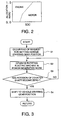
- Fig. 2 is a control map stored in the hybrid ECU 10 for setting an allocation ratio of the drive force between an output of the rotating electric machine 4 and an output of the engine 1 according to the SOC of the storage element 9 as a parameter.
- the hybrid ECU 10 determines the allocation ratio in accordance with the SOC information of the storage element 9 from the control map and, in order to generate a driver's required output corresponding to a detection signal of the acceleration sensor 13 (the required amount of acceleration), controls the output of the rotating electric machine 4 and the output of the engine 1 based upon the allocation ratio. That is, the hybrid ECU 10 controls the inverter 11 in such a way that the rotating electric machine 4 generates the allocated output and at the same time, transmits to the engine ECU 15 a command signal of a fuel supply amount required for generating an output which is allocated to the engine 1.
- the clutch 3 is disconnected and the inverter 11 is controlled in such a way as to obtain all of the required outputs corresponding to the accelerator pedal depressing amount from the rotating electric machine 4.
- the allocation ratio of the rotating electric machine 4 ⁇ 1 the allocation ratio of the engine 1 > 0
- the clutch 3 is connected, and the respective outputs of the engine 1 and the rotating electric machine 4 are summed up, which is inputted to the transmission 2.
- the engine ECU 15 and the inverter 11 are controlled so that, as the SOC of the storage element 9 decreases, the output of the rotating electric machine 4 is reduced and the output of the engine 1 is increased.
- an engine operation request to the engine ECU 15 is controlled in such a way that all the output equivalent to the accelerator pedal depressing amount is obtained from the engine 1.
- the hybrid ECU 10 controls the inverter 11 so that, to the extent that the charge to the storage element 9 is possible (within the range in which power generating is permissible in relation to the SOC) by cooperation control with the brake ECU 20, the regenerative braking force equivalent to the brake operational amount is obtained from the rotating electric machine 4 in a state where the clutch 3 is disconnected.
- the brake request is transmitted to the brake ECU 20 so that the braking force generated by the brake actuator 21 compensates for the braking force corresponding to the insufficient braking amount.
- the inverter 11 When the vehicle is not in a braking state and also a charge amount is insufficient based upon the SOC information of the storage element 9, i. e. when the request for the power generation is recognized, in a case where the clutch 3 is connected and an output of the engine 1 has an extra amount for a vehicle travel, the inverter 11 is controlled so that the rotating electric machine 4 is forced to serve as the electric generator to charge the storage element 9.
- the hybrid ECU 10 also functions to perform gearshift control at vehicle starting and traveling time.
- the hybrid ECU 10 causes the rotational speed of the input side of the transmission 2 to quickly converge to a region of the synchronizing rotational speed by operating the rotating electric machine 4 in the power generating mode or in the motor mode, in order to reduce a synchronizing time for gear setting when performing a gear shift of the transmission 2.
- Fig. 3 is a flow chart for explaining the gearshift control at the vehicle starting time.
- step S1 When the vehicle is stationary in a state where the engine 1 is running idle and the transmission is in a neutral position, the clutch 3 is first disconnected when the gear setting request to a vehicle-starting gear position occurs based upon a change lever operation (step S1).
- step S2 the inverter 11 is controlled so that the rotating electric machine 4 operates in the power generating mode.
- step S3 the rotational speed of the input side of the transmission 2 is reduced and converged to the region of the synchronizing rotational speed (in this case, since the vehicle is substantially not moving, the rotational speed is generally zero) in accordance with the required gear position for the rotational speed of the output side of the transmission 2, a request for gearshift of the transmission 2 from the neutral position to the required gear position is transmitted to the control unit 6 (step S3 and step S4).
- the allocation ratio in accordance with the SOC information of the storage element 9 is obtained from the control map (refer to Fig. 2) as described above, and based upon the allocation ratio and the accelerator pedal depressing amount, the connection and disconnection of the clutch 3, as well as the output of the rotating electric machine 4 and the output of the engine 1 are controlled.
- Fig. 4 is a flow chart for explaining gearshift control during vehicle traveling.
- the clutch 3 When the gearshift request occurs based upon the change lever operation during the vehicle traveling, the clutch 3 is disconnected, and a request for once setting the transmission to the neutral position is transmitted to the control unit 6 (steps S11 to S13). However, when the vehicle is motor-driven by operating the rotating electric machine 4 in the motor mode, the clutch 3 is in advance disconnected and therefore, the disconnected state of the clutch 3 is maintained as it is.
- a target rotational speed ⁇ of the input side of the transmission 2 is calculated from the detection signal of the vehicle speed sensor 18 and a gear ratio of the required gear position.
- the target rotational speed ⁇ When a gear position is normally shifted up from a low speed position to a high speed position, the target rotational speed ⁇ is reduced to a speed lower than the rotational speed of the input shaft side right before the gear shifting, and on the other hand, when the gear position is shifted down from a high speed position to a low speed position, the target rotational speed ⁇ increases.
- an actual rotational speed ⁇ of the input side of the transmission 2 is calculated from the detection signal (equivalent to the rotational speed of the rotating electric machine 4 of the gear rotational sensor 19 and a gear ratio of the gear box 5.
- a rotational speed difference ( ⁇ - ⁇ ) between the target rotational speed ⁇ and the actual rotational speed ⁇ is calculated.
- a step S 18 it is determined whether or not the actual rotational speed ⁇ is in a region of the synchronizing rotational speed for setting the gear of the transmission, which is obtained by adding a predetermined value ⁇ to the target rotational speed ⁇ . Specifically, it is determined whether or not the rotational speed difference ( ⁇ - ⁇ ) is within the predetermined value ⁇ .
- step S18 When the determination in the step S18 is affirmative, i.e. the actual rotational speed ⁇ has entered the synchronizing rotational speed region, the process proceeds to a step S19. On the other hand, when the determination in the step S18 is negative, i.e. the actual rotational speed ⁇ has not entered the synchronizing rotational speed region, the process proceeds to a step S20.
- step S20 it is determined whether or not the rotational speed difference ( ⁇ - ⁇ ) > 0 (the rotational speed difference is positive).
- the process proceeds to a step S21, wherein, in order to increase an actual rotational speed of the input side, an additional torque value of the rotating electric machine 4 in the motor mode is calculated in accordance with the rotational speed difference ( ⁇ - ⁇ ).
- step S22 the additional torque value is commanded to the inverter 11 to operate the rotating electric machine 4 in the motor mode and the process goes back to step S 18.
- step S20 When the determination in the step S20 is negative, i. e. the rotational speed difference is negative, the process proceeds to a step S23 in order to reduce the actual rotational speed ⁇ of the input side, wherein, a regenerative torque in accordance with the rotational speed difference ( ⁇ - ⁇ ) is obtained by operating the rotating electric machine 4 in the power generating mode.
- step S24 the regenerative torque value is commanded to the inverter 11 to operate the rotating electric machine 4 in the power generating mode and the process goes back to the step S18.
- the rotating electric machine 4 when the rotational speed difference satisfies the condition ( ⁇ - ⁇ ) ⁇ - ⁇ , the rotating electric machine 4 operates as an electric generator to generate the regenerative energy in accordance with the rotational speed difference ( ⁇ - ⁇ ), the actual rotational speed ⁇ of the input side of the transmission 2 is forced to be quickly reduced to the target rotational speed ⁇ corresponding to the required gear position. Therefore, the actual rotational speed ⁇ of the input side of the transmission 2 converges to the region of the synchronizing rotational speed of the required gear position for a short period of time.
- a gearshift control system for a hybrid vehicle according to the present invention may be applied to a hybrid drive system for various types of vehicles.
Applications Claiming Priority (1)
| Application Number | Priority Date | Filing Date | Title |
|---|---|---|---|
| PCT/JP2003/011661 WO2005025911A1 (ja) | 2003-09-11 | 2003-09-11 | ハイブリッド車両の変速制御装置 |
Publications (3)
| Publication Number | Publication Date |
|---|---|
| EP1669236A1 true EP1669236A1 (de) | 2006-06-14 |
| EP1669236A4 EP1669236A4 (de) | 2011-07-13 |
| EP1669236B1 EP1669236B1 (de) | 2018-08-29 |
Family
ID=34308217
Family Applications (1)
| Application Number | Title | Priority Date | Filing Date |
|---|---|---|---|
| EP03818662.3A Expired - Lifetime EP1669236B1 (de) | 2003-09-11 | 2003-09-11 | Gangschaltsteuervorrichtung für hybrid-elektro-fahrzeug |
Country Status (4)
| Country | Link |
|---|---|
| US (1) | US7416511B2 (de) |
| EP (1) | EP1669236B1 (de) |
| CN (1) | CN100528655C (de) |
| WO (1) | WO2005025911A1 (de) |
Cited By (4)
| Publication number | Priority date | Publication date | Assignee | Title |
|---|---|---|---|---|
| DE102007004463A1 (de) * | 2007-01-30 | 2008-08-21 | Zf Friedrichshafen Ag | Hybridantriebsanordnung für ein Fahrzeug mit einem Antriebsstrang |
| GB2462474A (en) * | 2008-08-09 | 2010-02-10 | Zeroshift Ltd | Transmission control which reduces shock when first gear is engaged with stationary vehicle |
| GB2570888A (en) * | 2018-02-07 | 2019-08-14 | Jaguar Land Rover Ltd | Control of a vehicle |
| GB2585503A (en) * | 2018-02-07 | 2021-01-13 | Jaguar Land Rover Ltd | Control of a vehicle |
Families Citing this family (23)
| Publication number | Priority date | Publication date | Assignee | Title |
|---|---|---|---|---|
| DE102004045269A1 (de) * | 2004-09-17 | 2006-04-13 | Bayerische Motoren Werke Ag | Antriebseinheit für ein Kraftfahrzeug mit Hybridantrieb |
| GB2421715B (en) * | 2004-12-22 | 2008-03-19 | Connaught Motor Co Ltd | Gearbox speed matching |
| CN100363651C (zh) * | 2005-05-26 | 2008-01-23 | 武汉理工大学 | 双离合自动变速动力耦合器 |
| CN101152837B (zh) * | 2006-09-29 | 2011-03-30 | 比亚迪股份有限公司 | 混合动力车驱动装置 |
| US7676313B2 (en) | 2006-10-12 | 2010-03-09 | Ford Global Technologies, Llc | Target speed control strategy for power-off shifts in a hybrid electric vehicle |
| DE102007001840A1 (de) * | 2007-01-12 | 2008-07-17 | Voith Patent Gmbh | Hybridantrieb, insbesondere für ein Kraftfahrzeug |
| SE530790C2 (sv) | 2007-01-17 | 2008-09-09 | Scania Cv Abp | Styrsystem |
| US7652447B2 (en) * | 2007-01-23 | 2010-01-26 | Gm Global Technology Operations, Inc. | Power capacitors for AC motors mounted diametrically on associated transmissions |
| JP5092540B2 (ja) * | 2007-05-24 | 2012-12-05 | トヨタ自動車株式会社 | 車両用動力伝達装置の制御装置 |
| US7837593B2 (en) * | 2007-11-12 | 2010-11-23 | Ford Global Technologies, Llc | Method and system for using mechanical power to operate a hybrid electric vehicle |
| AU2008355750B2 (en) * | 2008-04-28 | 2013-09-12 | Volvo Truck Corporation | Powertrain with input shaft and engine speed synchronization |
| BRPI0823042B1 (pt) * | 2008-08-29 | 2019-10-08 | Volvo Lastvagnar Ab | Sistema de tração para um veículo hibrido, unidade de controle eletrônico para controlar um sistema de tração para um veículo hibrido e metodo para controle de um sistema de tração veicular |
| JP4683137B2 (ja) * | 2009-03-14 | 2011-05-11 | トヨタ自動車株式会社 | 動力伝達装置の制御装置 |
| US9168825B2 (en) * | 2009-05-15 | 2015-10-27 | Ford Global Technologies, Llc | Hybrid electric vehicle and method for controlling a powertrain therein |
| US8618752B2 (en) | 2010-07-21 | 2013-12-31 | Superior Electron, Llc | System, architecture, and method for minimizing power consumption and increasing performance in electric vehicles |
| CN101985273A (zh) * | 2010-07-22 | 2011-03-16 | 浙江吉利汽车研究院有限公司 | 一种并联式混合动力汽车驱动系统 |
| CN102985666B (zh) * | 2011-07-01 | 2014-11-26 | 丰田自动车株式会社 | 车辆的驱动控制装置 |
| US8827865B2 (en) * | 2011-08-31 | 2014-09-09 | GM Global Technology Operations LLC | Control system for a hybrid powertrain system |
| DE102011112091A1 (de) * | 2011-09-02 | 2013-03-07 | Lsp Innovative Automotive Systems Gmbh | Elektrisches Antriebssystem für ein batteriegetriebenes Leichtfahrzeug |
| JP6045360B2 (ja) * | 2013-01-17 | 2016-12-14 | アイシン・エーアイ株式会社 | ハイブリッド車両用駆動装置 |
| SE538355C2 (sv) * | 2013-11-21 | 2016-05-24 | Scania Cv Ab | Förfarande för att styra en hybriddrivlina i ett fordon så att glapp elimineras medelst en elmaskin |
| JP6525146B2 (ja) * | 2015-04-24 | 2019-06-05 | 三菱自動車工業株式会社 | シフト制御装置 |
| JP2019014449A (ja) * | 2017-07-10 | 2019-01-31 | トヨタ自動車株式会社 | 車両用動力伝達装置 |
Citations (2)
| Publication number | Priority date | Publication date | Assignee | Title |
|---|---|---|---|---|
| WO1997008439A1 (de) * | 1995-08-31 | 1997-03-06 | Isad Electronic Systems Gmbh & Co. Kg | Antriebssystem mit antriebsmotor, elektrischer maschine und batterie |
| US20030045389A1 (en) * | 2001-08-31 | 2003-03-06 | Honda Giken Kogyo Kabushiki Kaisha | Power transmission apparatus for a hybrid vehicle and a method for controlling the apparatus |
Family Cites Families (10)
| Publication number | Priority date | Publication date | Assignee | Title |
|---|---|---|---|---|
| JPS61138635A (ja) | 1984-12-10 | 1986-06-26 | Sunstar Giken Kk | インストルメントパネルパッド用表面軟質ポリ塩化ビニルシート材 |
| JPS61138635U (de) * | 1985-02-18 | 1986-08-28 | ||
| JPS63154437A (ja) | 1986-12-19 | 1988-06-27 | Honda Motor Co Ltd | 歯車変速機の電気的同期装置 |
| JP3404195B2 (ja) | 1995-09-26 | 2003-05-06 | 株式会社エクォス・リサーチ | 車両の同期制御装置 |
| JP3354074B2 (ja) | 1997-04-25 | 2002-12-09 | ジヤトコ株式会社 | パラレルハイブリッド車両の制御装置 |
| US5993350A (en) * | 1997-12-01 | 1999-11-30 | Lawrie; Robert E. | Automated manual transmission clutch controller |
| JP2000343965A (ja) * | 1999-06-08 | 2000-12-12 | Nissan Diesel Motor Co Ltd | ハイブリッド車両 |
| JP4585061B2 (ja) | 1999-09-28 | 2010-11-24 | 富士重工業株式会社 | 電気自動車の制御方法 |
| KR20040030430A (ko) * | 2000-10-16 | 2004-04-09 | 닛산 디젤 고교 가부시끼가이샤 | 차량의 하이브리드 시스템 |
| JP4070401B2 (ja) | 2000-10-31 | 2008-04-02 | 日産ディーゼル工業株式会社 | 車両のハイブリッドシステム |
-
2003
- 2003-09-11 WO PCT/JP2003/011661 patent/WO2005025911A1/ja active Application Filing
- 2003-09-11 US US10/568,274 patent/US7416511B2/en not_active Expired - Lifetime
- 2003-09-11 EP EP03818662.3A patent/EP1669236B1/de not_active Expired - Lifetime
- 2003-09-11 CN CNB03827065XA patent/CN100528655C/zh not_active Expired - Lifetime
Patent Citations (2)
| Publication number | Priority date | Publication date | Assignee | Title |
|---|---|---|---|---|
| WO1997008439A1 (de) * | 1995-08-31 | 1997-03-06 | Isad Electronic Systems Gmbh & Co. Kg | Antriebssystem mit antriebsmotor, elektrischer maschine und batterie |
| US20030045389A1 (en) * | 2001-08-31 | 2003-03-06 | Honda Giken Kogyo Kabushiki Kaisha | Power transmission apparatus for a hybrid vehicle and a method for controlling the apparatus |
Non-Patent Citations (2)
| Title |
|---|
| BERGER R ET AL: "ESG - Elektrisches Schaltgetriebe", ATZ AUTOMOBILTECHNISCHE ZEITSCHRIFT, VIEWEG PUBLISHING, WIESBADEN, DE, vol. 107, no. 6, 1 June 2005 (2005-06-01), pages 488-493,495, XP001519133, ISSN: 0001-2785 * |
| See also references of WO2005025911A1 * |
Cited By (6)
| Publication number | Priority date | Publication date | Assignee | Title |
|---|---|---|---|---|
| DE102007004463A1 (de) * | 2007-01-30 | 2008-08-21 | Zf Friedrichshafen Ag | Hybridantriebsanordnung für ein Fahrzeug mit einem Antriebsstrang |
| GB2462474A (en) * | 2008-08-09 | 2010-02-10 | Zeroshift Ltd | Transmission control which reduces shock when first gear is engaged with stationary vehicle |
| GB2570888A (en) * | 2018-02-07 | 2019-08-14 | Jaguar Land Rover Ltd | Control of a vehicle |
| GB2570888B (en) * | 2018-02-07 | 2020-09-02 | Jaguar Land Rover Ltd | Transmission operation in a vehicle with an electric motor |
| GB2585503A (en) * | 2018-02-07 | 2021-01-13 | Jaguar Land Rover Ltd | Control of a vehicle |
| GB2585503B (en) * | 2018-02-07 | 2021-09-01 | Jaguar Land Rover Ltd | Transmission operation in a vehicle with an electric motor |
Also Published As
| Publication number | Publication date |
|---|---|
| US7416511B2 (en) | 2008-08-26 |
| EP1669236B1 (de) | 2018-08-29 |
| CN1839065A (zh) | 2006-09-27 |
| EP1669236A4 (de) | 2011-07-13 |
| CN100528655C (zh) | 2009-08-19 |
| WO2005025911A1 (ja) | 2005-03-24 |
| US20060293144A1 (en) | 2006-12-28 |
Similar Documents
| Publication | Publication Date | Title |
|---|---|---|
| US7416511B2 (en) | Gear shift control system of hybrid vehicle | |
| EP1354746B1 (de) | Hybrides fahrzeugsystem | |
| KR100504053B1 (ko) | 하이브리드 차량 | |
| US7498757B2 (en) | Control device for a hybrid electric vehicle | |
| US6884199B2 (en) | Hybrid vehicle system | |
| US7328763B2 (en) | Hybrid drive system of vehicle | |
| CN102958771B (zh) | 车辆及车辆的控制方法 | |
| US7100719B2 (en) | Hybrid-powered vehicle | |
| US20070219045A1 (en) | Control device for a hybrid electric vehicle | |
| CN103068650B (zh) | 车辆及其控制方法 | |
| JP2006226440A (ja) | ハイブリッド車両の電動オイルポンプ制御装置 | |
| US20050051371A1 (en) | Method for controlling a wheel drive system of a hybrid vehicle | |
| EP1491378B1 (de) | Steuervorrichtung für hybridfahrzeug | |
| KR20160139650A (ko) | 마일드 하이브리드 자동차의 에너지 회생 장치 및 방법 | |
| EP2990286A1 (de) | Fahrzeugsteuerungsvorrichtung | |
| JP3940260B2 (ja) | 車両のハイブリッドシステム | |
| JP2002120602A (ja) | 車両のハイブリッドシステム | |
| WO2022172388A1 (ja) | ハイブリッドシステム | |
| WO2015068482A1 (ja) | ハイブリッド車両の制御装置 | |
| JP2003274510A (ja) | 車両のハイブリッドシステム | |
| JP4005853B2 (ja) | 車両の発進制御装置 | |
| JP2013209044A (ja) | ハイブリッド電気自動車の制御装置 |
Legal Events
| Date | Code | Title | Description |
|---|---|---|---|
| PUAI | Public reference made under article 153(3) epc to a published international application that has entered the european phase |
Free format text: ORIGINAL CODE: 0009012 |
|
| 17P | Request for examination filed |
Effective date: 20060215 |
|
| AK | Designated contracting states |
Kind code of ref document: A1 Designated state(s): DE FR |
|
| RBV | Designated contracting states (corrected) |
Designated state(s): DE FR |
|
| REG | Reference to a national code |
Ref country code: DE Ref legal event code: R079 Ref document number: 60351438 Country of ref document: DE Free format text: PREVIOUS MAIN CLASS: B60K0006040000 Ipc: F16H0061040000 Ref country code: DE Ref legal event code: R079 Free format text: PREVIOUS MAIN CLASS: B60K0006040000 Ipc: F16H0061040000 |
|
| A4 | Supplementary search report drawn up and despatched |
Effective date: 20110610 |
|
| RIC1 | Information provided on ipc code assigned before grant |
Ipc: F16H 61/04 20060101AFI20110606BHEP |
|
| 17Q | First examination report despatched |
Effective date: 20170601 |
|
| GRAP | Despatch of communication of intention to grant a patent |
Free format text: ORIGINAL CODE: EPIDOSNIGR1 |
|
| RAP1 | Party data changed (applicant data changed or rights of an application transferred) |
Owner name: NISSAN DIESEL MOTOR CO., LTD. |
|
| RIN1 | Information on inventor provided before grant (corrected) |
Inventor name: NISHINA, MITSUHIRO Inventor name: GOUDA, HIDEAKI Inventor name: SUZUKI, YUJI |
|
| INTG | Intention to grant announced |
Effective date: 20180321 |
|
| GRAS | Grant fee paid |
Free format text: ORIGINAL CODE: EPIDOSNIGR3 |
|
| GRAA | (expected) grant |
Free format text: ORIGINAL CODE: 0009210 |
|
| REG | Reference to a national code |
Ref country code: DE Ref legal event code: R081 Ref document number: 60351438 Country of ref document: DE Owner name: VOLVO TRUCK CORPORATION, SE Free format text: FORMER OWNER: NISSAN DIESEL MOTOR CO., LTD., AGEO, SAITAMA, JP |
|
| AK | Designated contracting states |
Kind code of ref document: B1 Designated state(s): DE FR |
|
| REG | Reference to a national code |
Ref country code: FR Ref legal event code: PLFP Year of fee payment: 16 |
|
| REG | Reference to a national code |
Ref country code: DE Ref legal event code: R096 Ref document number: 60351438 Country of ref document: DE |
|
| REG | Reference to a national code |
Ref country code: DE Ref legal event code: R097 Ref document number: 60351438 Country of ref document: DE |
|
| PLBE | No opposition filed within time limit |
Free format text: ORIGINAL CODE: 0009261 |
|
| STAA | Information on the status of an ep patent application or granted ep patent |
Free format text: STATUS: NO OPPOSITION FILED WITHIN TIME LIMIT |
|
| 26N | No opposition filed |
Effective date: 20190531 |
|
| REG | Reference to a national code |
Ref country code: DE Ref legal event code: R081 Ref document number: 60351438 Country of ref document: DE Owner name: VOLVO TRUCK CORPORATION, SE Free format text: FORMER OWNER: NISSAN DIESEL MOTOR CO., LTD., AGEO-SHI, SAITAMA-KEN, JP |
|
| PGFP | Annual fee paid to national office [announced via postgrant information from national office to epo] |
Ref country code: DE Payment date: 20220527 Year of fee payment: 20 |
|
| PGFP | Annual fee paid to national office [announced via postgrant information from national office to epo] |
Ref country code: FR Payment date: 20220927 Year of fee payment: 20 |
|
| REG | Reference to a national code |
Ref country code: DE Ref legal event code: R071 Ref document number: 60351438 Country of ref document: DE |