EP1669142A1 - Verfahren zum Prägen eines Behälterkörpers an einer genauen Position - Google Patents
Verfahren zum Prägen eines Behälterkörpers an einer genauen Position Download PDFInfo
- Publication number
- EP1669142A1 EP1669142A1 EP04257642A EP04257642A EP1669142A1 EP 1669142 A1 EP1669142 A1 EP 1669142A1 EP 04257642 A EP04257642 A EP 04257642A EP 04257642 A EP04257642 A EP 04257642A EP 1669142 A1 EP1669142 A1 EP 1669142A1
- Authority
- EP
- European Patent Office
- Prior art keywords
- container body
- embossing
- reference mark
- outer die
- predetermined
- Prior art date
- Legal status (The legal status is an assumption and is not a legal conclusion. Google has not performed a legal analysis and makes no representation as to the accuracy of the status listed.)
- Granted
Links
- 238000004049 embossing Methods 0.000 title claims abstract description 35
- 238000000034 method Methods 0.000 title claims abstract description 15
- 230000000712 assembly Effects 0.000 claims abstract description 19
- 238000000429 assembly Methods 0.000 claims abstract description 19
- 230000005540 biological transmission Effects 0.000 description 3
- 238000007796 conventional method Methods 0.000 description 3
- 238000006073 displacement reaction Methods 0.000 description 2
- 239000000758 substrate Substances 0.000 description 2
- 239000005028 tinplate Substances 0.000 description 2
- 238000010586 diagram Methods 0.000 description 1
- 238000003466 welding Methods 0.000 description 1
Images



Classifications
-
- B—PERFORMING OPERATIONS; TRANSPORTING
- B21—MECHANICAL METAL-WORKING WITHOUT ESSENTIALLY REMOVING MATERIAL; PUNCHING METAL
- B21D—WORKING OR PROCESSING OF SHEET METAL OR METAL TUBES, RODS OR PROFILES WITHOUT ESSENTIALLY REMOVING MATERIAL; PUNCHING METAL
- B21D51/00—Making hollow objects
- B21D51/16—Making hollow objects characterised by the use of the objects
- B21D51/26—Making hollow objects characterised by the use of the objects cans or tins; Closing same in a permanent manner
-
- B—PERFORMING OPERATIONS; TRANSPORTING
- B21—MECHANICAL METAL-WORKING WITHOUT ESSENTIALLY REMOVING MATERIAL; PUNCHING METAL
- B21D—WORKING OR PROCESSING OF SHEET METAL OR METAL TUBES, RODS OR PROFILES WITHOUT ESSENTIALLY REMOVING MATERIAL; PUNCHING METAL
- B21D17/00—Forming single grooves in sheet metal or tubular or hollow articles
- B21D17/02—Forming single grooves in sheet metal or tubular or hollow articles by pressing
- B21D17/025—Forming single grooves in sheet metal or tubular or hollow articles by pressing by pressing tubes axially
Definitions
- the invention relates to a method for embossing a container body, more particularly to a method for embossing a container body at a precise position.
- a conventional method for embossing a container body 1 includes the steps of:
- the container body 1 formed with the recess pattern 2 and/or the protrusion pattern 3 can be made by the aforesaid conventional method, the conventional method can not emboss the pattern at a precise position of the container body 1.
- the object of the present invention is to provide a method for embossing a container body at a precise position.
- a method for embossing a container body at a precise position of this invention includes the steps of:
- the preferred embodiment of the method for embossing a container body at a precise position includes the following steps:
- a substrate such as a tin plate, undergoes monochrome or color printing, and is cut to form a sheet of a predetermined size.
- the sheet is rolled and welded to form a container body 40.
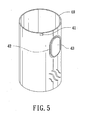
- the container body 40 as formed has a first reference mark 41 and a forming area 42 on a tubular wall thereof.
- the first reference mark 41 can be a rectangular mark or any other suitable mark which is recognizable.
- the forming area 42 maybe provided with printed pattern if desired.
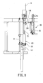
- the container body 40 is held vertically on a platform 10. In this preferred embodiment, the container body 40 is held on the platform 10 using a magnetic mechanism.
- the container body 40 on the platform 10 is rotated relative to the platform 10 until the first reference mark 41 reaches a predetermined first angular position.
- the rotation of the container body 40 is driven by a first servo-motor 12.
- a first sensor 11 mounted on the platform 10 is used to detect the predetermined first angular position of the first reference mark 41.
- the first sensor 11 is a photoelectric sensor, and is associated with control software to control the first servo-motor 12.
- the data of the relative distance between the first reference mark 41 and the forming area 42 to be embossed is stored in the first sensor 11.
- the platform 10 is moved vertically so as to move the container body 40 to an embossing region 20 where the container body 40 is sleeved around an inner die assembly 21, and where an outer die assembly 22 is disposed outwardly of the container body 40.
- the inner and outer die assemblies 21,22 are provided with inner and outer embossing portions (not shown), respectively, which are aligned with the forming area 42 of the container body 40 in this step.
- One of the inner and outer embossing portions is a recess portion, whereas the other of the inner and outer embossing portions is a protrusionportion corresponding to the recess portion.
- the inner die assembly 21 is additionally provided with a second reference mark (not shown), and is driven by a second servo-motor 13.
- the inner and outer die assemblies 21,22 can be rotated simultaneously by a transmission belt 14.
- the second sensor 23 is a photoelectric sensor, and is associated with another control software to control the second servo-motor 13.
- the data of the relative distance between the first reference mark 41 and the forming area 42 to be embossed is stored in the second sensor 23.
- the inner and outer die assemblies 21,22 are placed at a position operative for embossing the container body 40.
- the displacement of the inner die assembly 21 relative to the outer die assembly 22 can occur after a repeated operation of the method of this invention.
- the displacement can be detected using the second sensor 23 to detect the second reference mark so as to permit placing of the inner and outer die assemblies 21,22 at the position operative for embossing the container body 40 prior to embossing.
- the inner and outer die assemblies 21,22 are moved toward each other.
- the container body 40 is embossed with a pattern 43 (best shown in Figure 5) at a position (i.e., forming area 42) which is predetermined relative to the position of the first reference mark 41 through the inner and outer die assemblies 21,22.
- the inner die assembly 21 is rotated by the second servo-motor 13, and the outer die assembly 22 is rotated simultaneously through the transmission belt 14.
- the inner die assembly 21 is rotated until the second reference mark on the inner die assembly 21 reaches a predetermined second angular position as detected by the second sensor 23 so as to stop the embossing.
- the inner and outer die assemblies 21,22 are separated from each other, and the platform 10 is moved away from the embossing region 20 so as to remove the container body 40 formed with the pattern 43 at the forming area 42 away from the platform 10.
Landscapes
- Engineering & Computer Science (AREA)
- Mechanical Engineering (AREA)
- Making Paper Articles (AREA)
- Shaping Of Tube Ends By Bending Or Straightening (AREA)
- Details Of Rigid Or Semi-Rigid Containers (AREA)
Priority Applications (2)
| Application Number | Priority Date | Filing Date | Title |
|---|---|---|---|
| EP20040257642 EP1669142B1 (de) | 2004-12-09 | 2004-12-09 | Verfahren zum Prägen eines Behälterkörpers an einer genauen Position |
| DE602004005728T DE602004005728T2 (de) | 2004-12-09 | 2004-12-09 | Verfahren zum Prägen eines Behälterkörpers an einer genauen Position |
Applications Claiming Priority (1)
| Application Number | Priority Date | Filing Date | Title |
|---|---|---|---|
| EP20040257642 EP1669142B1 (de) | 2004-12-09 | 2004-12-09 | Verfahren zum Prägen eines Behälterkörpers an einer genauen Position |
Publications (2)
| Publication Number | Publication Date |
|---|---|
| EP1669142A1 true EP1669142A1 (de) | 2006-06-14 |
| EP1669142B1 EP1669142B1 (de) | 2007-04-04 |
Family
ID=34930899
Family Applications (1)
| Application Number | Title | Priority Date | Filing Date |
|---|---|---|---|
| EP20040257642 Expired - Lifetime EP1669142B1 (de) | 2004-12-09 | 2004-12-09 | Verfahren zum Prägen eines Behälterkörpers an einer genauen Position |
Country Status (2)
| Country | Link |
|---|---|
| EP (1) | EP1669142B1 (de) |
| DE (1) | DE602004005728T2 (de) |
Cited By (5)
| Publication number | Priority date | Publication date | Assignee | Title |
|---|---|---|---|---|
| ITMO20090141A1 (it) * | 2009-05-26 | 2010-11-27 | Sacmi | Metodo e apparato di goffratura |
| WO2010136496A3 (en) * | 2009-05-26 | 2011-01-27 | Sacmi Cooperativa Meccanici Imola Societa' Cooperativa | Embossing method and apparatus |
| CN102441615A (zh) * | 2011-12-31 | 2012-05-09 | 苏州三维精密机械有限公司 | 杯形零件侧面成型模具 |
| US9491646B2 (en) | 2011-06-10 | 2016-11-08 | Rohde & Schwarz Gmbh & Co. Kg | Measuring device and a method for measuring a signal with several component signals |
| WO2018224840A3 (en) * | 2017-06-08 | 2019-01-10 | Envases (Uk) Limited | DEFORMATION OF THIN-WHEEL BODY BY ALIGNED SHAPING |
Citations (3)
| Publication number | Priority date | Publication date | Assignee | Title |
|---|---|---|---|---|
| US5893286A (en) * | 1996-07-19 | 1999-04-13 | Aluminum Company Of America | Apparatus and method for the registered embossing of containers |
| US6338263B1 (en) * | 1999-06-30 | 2002-01-15 | Toyo Seikan Kaisha, Ltd. | Method for manufacturing embossed can body, inspecting apparatus used for manufacturing embossed can body, and inspecting method used therefor |
| US20030074946A1 (en) * | 2000-02-10 | 2003-04-24 | Campo Santiago Garcia | Deformation of thin walled bodies |
-
2004
- 2004-12-09 DE DE602004005728T patent/DE602004005728T2/de not_active Expired - Lifetime
- 2004-12-09 EP EP20040257642 patent/EP1669142B1/de not_active Expired - Lifetime
Patent Citations (3)
| Publication number | Priority date | Publication date | Assignee | Title |
|---|---|---|---|---|
| US5893286A (en) * | 1996-07-19 | 1999-04-13 | Aluminum Company Of America | Apparatus and method for the registered embossing of containers |
| US6338263B1 (en) * | 1999-06-30 | 2002-01-15 | Toyo Seikan Kaisha, Ltd. | Method for manufacturing embossed can body, inspecting apparatus used for manufacturing embossed can body, and inspecting method used therefor |
| US20030074946A1 (en) * | 2000-02-10 | 2003-04-24 | Campo Santiago Garcia | Deformation of thin walled bodies |
Cited By (9)
| Publication number | Priority date | Publication date | Assignee | Title |
|---|---|---|---|---|
| ITMO20090141A1 (it) * | 2009-05-26 | 2010-11-27 | Sacmi | Metodo e apparato di goffratura |
| WO2010136496A3 (en) * | 2009-05-26 | 2011-01-27 | Sacmi Cooperativa Meccanici Imola Societa' Cooperativa | Embossing method and apparatus |
| US9296033B2 (en) | 2009-05-26 | 2016-03-29 | Sacmi Cooperativa Meccanici Imola Societa' Cooperativa | Embossing method and apparatus |
| US10022774B2 (en) | 2009-05-26 | 2018-07-17 | Sacmi Cooperativa Meccanici Imola Societa' Cooperativa | Embossing method and apparatus |
| US9491646B2 (en) | 2011-06-10 | 2016-11-08 | Rohde & Schwarz Gmbh & Co. Kg | Measuring device and a method for measuring a signal with several component signals |
| CN102441615A (zh) * | 2011-12-31 | 2012-05-09 | 苏州三维精密机械有限公司 | 杯形零件侧面成型模具 |
| CN102441615B (zh) * | 2011-12-31 | 2014-04-23 | 苏州三维精密机械有限公司 | 杯形零件侧面成型模具 |
| WO2018224840A3 (en) * | 2017-06-08 | 2019-01-10 | Envases (Uk) Limited | DEFORMATION OF THIN-WHEEL BODY BY ALIGNED SHAPING |
| US11919063B2 (en) | 2017-06-08 | 2024-03-05 | Envases (Uk) Limited | Deformation of thin walled bodies by registered shaping |
Also Published As
| Publication number | Publication date |
|---|---|
| DE602004005728D1 (de) | 2007-05-16 |
| DE602004005728T2 (de) | 2007-12-27 |
| EP1669142B1 (de) | 2007-04-04 |
Similar Documents
| Publication | Publication Date | Title |
|---|---|---|
| JP2012512766A (ja) | ウェブ状材料上の印刷によるパターンと印刷によらないパターンとの間の相対位置を制御する方法及び該方法において使用される装置 | |
| US9592569B2 (en) | Method and apparatus for forming visible indicium on the tab portion of a beverage container | |
| EP2242595B1 (de) | Druckplatten | |
| US12076829B2 (en) | Machine integrated positioning system | |
| CA2481557A1 (en) | Improved method and apparatus for precision cutting of graphics areas from sheets | |
| EP1669142B1 (de) | Verfahren zum Prägen eines Behälterkörpers an einer genauen Position | |
| WO2004042654A3 (en) | Improved method for preparing graphics on sheets | |
| JP3478185B2 (ja) | エンボス加工缶体の製造方法 | |
| JP2011171388A (ja) | プリント基板用コネクタ圧入装置、及び電子部品の製造方法 | |
| EP2857187B1 (de) | Vorrichtung und Verfahren zur Herstellung von geprägten Klappen oder Etiketten für Verpackungen | |
| JPH03123010A (ja) | 積層電子部品の製造方法 | |
| US5214990A (en) | Method and system for punching holes in a sheet material | |
| CN114987065B (zh) | 一种打标装置及防伪打标方法 | |
| EP1342516A2 (de) | Formwalzen eines nicht-zirkulares Querschnittes | |
| JP3554313B2 (ja) | 刷版加工装置 | |
| JP2960060B1 (ja) | テープ状物の穿孔機 | |
| JP3100181U (ja) | 全自動線上位置合わせパンチ装置 | |
| JP3137395U (ja) | リユースcad面版 | |
| JP2708886B2 (ja) | シート状体の孔加工方法 | |
| JP2003019697A (ja) | 枚葉シート打抜き製造機における送り制御装置 | |
| JP4216388B2 (ja) | 基板バックアップ装置におけるバックアップピンのセット方法 | |
| JP5979470B2 (ja) | 打抜機 | |
| JP3478181B2 (ja) | 缶 体 | |
| JP4408240B2 (ja) | 打抜用見当マーク | |
| JP6897937B2 (ja) | フレキシブルプリント配線板の製造方法、板状治具、フレキシブルプリント配線板個片のハンドリング用具及びフレキシブルプリント配線板の製造設備 |
Legal Events
| Date | Code | Title | Description |
|---|---|---|---|
| GRAP | Despatch of communication of intention to grant a patent |
Free format text: ORIGINAL CODE: EPIDOSNIGR1 |
|
| PUAI | Public reference made under article 153(3) epc to a published international application that has entered the european phase |
Free format text: ORIGINAL CODE: 0009012 |
|
| 17P | Request for examination filed |
Effective date: 20051111 |
|
| AK | Designated contracting states |
Kind code of ref document: A1 Designated state(s): AT BE BG CH CY CZ DE DK EE ES FI FR GB GR HU IE IS IT LI LT LU MC NL PL PT RO SE SI SK TR |
|
| AX | Request for extension of the european patent |
Extension state: AL BA HR LV MK YU |
|
| GRAS | Grant fee paid |
Free format text: ORIGINAL CODE: EPIDOSNIGR3 |
|
| AKX | Designation fees paid |
Designated state(s): DE FR GB IT |
|
| GRAA | (expected) grant |
Free format text: ORIGINAL CODE: 0009210 |
|
| AK | Designated contracting states |
Kind code of ref document: B1 Designated state(s): DE FR GB IT |
|
| REG | Reference to a national code |
Ref country code: GB Ref legal event code: FG4D |
|
| REF | Corresponds to: |
Ref document number: 602004005728 Country of ref document: DE Date of ref document: 20070516 Kind code of ref document: P |
|
| ET | Fr: translation filed | ||
| PLBE | No opposition filed within time limit |
Free format text: ORIGINAL CODE: 0009261 |
|
| STAA | Information on the status of an ep patent application or granted ep patent |
Free format text: STATUS: NO OPPOSITION FILED WITHIN TIME LIMIT |
|
| 26N | No opposition filed |
Effective date: 20080107 |
|
| PGFP | Annual fee paid to national office [announced via postgrant information from national office to epo] |
Ref country code: IT Payment date: 20081223 Year of fee payment: 5 |
|
| PGFP | Annual fee paid to national office [announced via postgrant information from national office to epo] |
Ref country code: GB Payment date: 20081204 Year of fee payment: 5 |
|
| PGFP | Annual fee paid to national office [announced via postgrant information from national office to epo] |
Ref country code: FR Payment date: 20081128 Year of fee payment: 5 |
|
| PGFP | Annual fee paid to national office [announced via postgrant information from national office to epo] |
Ref country code: DE Payment date: 20091230 Year of fee payment: 6 |
|
| GBPC | Gb: european patent ceased through non-payment of renewal fee |
Effective date: 20091209 |
|
| REG | Reference to a national code |
Ref country code: FR Ref legal event code: ST Effective date: 20100831 |
|
| PG25 | Lapsed in a contracting state [announced via postgrant information from national office to epo] |
Ref country code: FR Free format text: LAPSE BECAUSE OF NON-PAYMENT OF DUE FEES Effective date: 20091231 |
|
| PG25 | Lapsed in a contracting state [announced via postgrant information from national office to epo] |
Ref country code: GB Free format text: LAPSE BECAUSE OF NON-PAYMENT OF DUE FEES Effective date: 20091209 |
|
| PG25 | Lapsed in a contracting state [announced via postgrant information from national office to epo] |
Ref country code: IT Free format text: LAPSE BECAUSE OF NON-PAYMENT OF DUE FEES Effective date: 20091209 |
|
| REG | Reference to a national code |
Ref country code: DE Ref legal event code: R119 Ref document number: 602004005728 Country of ref document: DE Effective date: 20110701 |
|
| PG25 | Lapsed in a contracting state [announced via postgrant information from national office to epo] |
Ref country code: DE Free format text: LAPSE BECAUSE OF NON-PAYMENT OF DUE FEES Effective date: 20110701 |