EP1666435B1 - Method of manufacturing a honeycomb structure - Google Patents
Method of manufacturing a honeycomb structure Download PDFInfo
- Publication number
- EP1666435B1 EP1666435B1 EP04732502.2A EP04732502A EP1666435B1 EP 1666435 B1 EP1666435 B1 EP 1666435B1 EP 04732502 A EP04732502 A EP 04732502A EP 1666435 B1 EP1666435 B1 EP 1666435B1
- Authority
- EP
- European Patent Office
- Prior art keywords
- honeycomb
- adhesive agent
- honeycomb segments
- segments
- rows
- Prior art date
- Legal status (The legal status is an assumption and is not a legal conclusion. Google has not performed a legal analysis and makes no representation as to the accuracy of the status listed.)
- Expired - Lifetime
Links
Images


Classifications
-
- B—PERFORMING OPERATIONS; TRANSPORTING
- B01—PHYSICAL OR CHEMICAL PROCESSES OR APPARATUS IN GENERAL
- B01D—SEPARATION
- B01D46/00—Filters or filtering processes specially modified for separating dispersed particles from gases or vapours
- B01D46/0001—Making filtering elements
-
- C—CHEMISTRY; METALLURGY
- C04—CEMENTS; CONCRETE; ARTIFICIAL STONE; CERAMICS; REFRACTORIES
- C04B—LIME, MAGNESIA; SLAG; CEMENTS; COMPOSITIONS THEREOF, e.g. MORTARS, CONCRETE OR LIKE BUILDING MATERIALS; ARTIFICIAL STONE; CERAMICS; REFRACTORIES; TREATMENT OF NATURAL STONE
- C04B37/00—Joining burned ceramic articles with other burned ceramic articles or other articles by heating
-
- B—PERFORMING OPERATIONS; TRANSPORTING
- B01—PHYSICAL OR CHEMICAL PROCESSES OR APPARATUS IN GENERAL
- B01D—SEPARATION
- B01D39/00—Filtering material for liquid or gaseous fluids
- B01D39/14—Other self-supporting filtering material ; Other filtering material
- B01D39/20—Other self-supporting filtering material ; Other filtering material of inorganic material, e.g. asbestos paper, metallic filtering material of non-woven wires
-
- B—PERFORMING OPERATIONS; TRANSPORTING
- B01—PHYSICAL OR CHEMICAL PROCESSES OR APPARATUS IN GENERAL
- B01D—SEPARATION
- B01D46/00—Filters or filtering processes specially modified for separating dispersed particles from gases or vapours
-
- B—PERFORMING OPERATIONS; TRANSPORTING
- B01—PHYSICAL OR CHEMICAL PROCESSES OR APPARATUS IN GENERAL
- B01D—SEPARATION
- B01D46/00—Filters or filtering processes specially modified for separating dispersed particles from gases or vapours
- B01D46/24—Particle separators, e.g. dust precipitators, using rigid hollow filter bodies
- B01D46/2403—Particle separators, e.g. dust precipitators, using rigid hollow filter bodies characterised by the physical shape or structure of the filtering element
- B01D46/2418—Honeycomb filters
- B01D46/2451—Honeycomb filters characterized by the geometrical structure, shape, pattern or configuration or parameters related to the geometry of the structure
- B01D46/2455—Honeycomb filters characterized by the geometrical structure, shape, pattern or configuration or parameters related to the geometry of the structure of the whole honeycomb or segments
-
- B—PERFORMING OPERATIONS; TRANSPORTING
- B01—PHYSICAL OR CHEMICAL PROCESSES OR APPARATUS IN GENERAL
- B01D—SEPARATION
- B01D46/00—Filters or filtering processes specially modified for separating dispersed particles from gases or vapours
- B01D46/24—Particle separators, e.g. dust precipitators, using rigid hollow filter bodies
- B01D46/2403—Particle separators, e.g. dust precipitators, using rigid hollow filter bodies characterised by the physical shape or structure of the filtering element
- B01D46/2418—Honeycomb filters
- B01D46/2451—Honeycomb filters characterized by the geometrical structure, shape, pattern or configuration or parameters related to the geometry of the structure
- B01D46/2478—Structures comprising honeycomb segments
-
- B—PERFORMING OPERATIONS; TRANSPORTING
- B01—PHYSICAL OR CHEMICAL PROCESSES OR APPARATUS IN GENERAL
- B01D—SEPARATION
- B01D46/00—Filters or filtering processes specially modified for separating dispersed particles from gases or vapours
- B01D46/24—Particle separators, e.g. dust precipitators, using rigid hollow filter bodies
- B01D46/2403—Particle separators, e.g. dust precipitators, using rigid hollow filter bodies characterised by the physical shape or structure of the filtering element
- B01D46/2418—Honeycomb filters
- B01D46/2451—Honeycomb filters characterized by the geometrical structure, shape, pattern or configuration or parameters related to the geometry of the structure
- B01D46/2486—Honeycomb filters characterized by the geometrical structure, shape, pattern or configuration or parameters related to the geometry of the structure characterised by the shapes or configurations
- B01D46/249—Quadrangular e.g. square or diamond
-
- B—PERFORMING OPERATIONS; TRANSPORTING
- B28—WORKING CEMENT, CLAY, OR STONE
- B28B—SHAPING CLAY OR OTHER CERAMIC COMPOSITIONS; SHAPING SLAG; SHAPING MIXTURES CONTAINING CEMENTITIOUS MATERIAL, e.g. PLASTER
- B28B1/00—Producing shaped prefabricated articles from the material
- B28B1/002—Producing shaped prefabricated articles from the material assembled from preformed elements
-
- B—PERFORMING OPERATIONS; TRANSPORTING
- B32—LAYERED PRODUCTS
- B32B—LAYERED PRODUCTS, i.e. PRODUCTS BUILT-UP OF STRATA OF FLAT OR NON-FLAT, e.g. CELLULAR OR HONEYCOMB, FORM
- B32B18/00—Layered products essentially comprising ceramics, e.g. refractory products
-
- F—MECHANICAL ENGINEERING; LIGHTING; HEATING; WEAPONS; BLASTING
- F01—MACHINES OR ENGINES IN GENERAL; ENGINE PLANTS IN GENERAL; STEAM ENGINES
- F01N—GAS-FLOW SILENCERS OR EXHAUST APPARATUS FOR MACHINES OR ENGINES IN GENERAL; GAS-FLOW SILENCERS OR EXHAUST APPARATUS FOR INTERNAL-COMBUSTION ENGINES
- F01N13/00—Exhaust or silencing apparatus characterised by constructional features
- F01N13/011—Exhaust or silencing apparatus characterised by constructional features having two or more purifying devices arranged in parallel
- F01N13/017—Exhaust or silencing apparatus characterised by constructional features having two or more purifying devices arranged in parallel the purifying devices are arranged in a single housing
-
- F—MECHANICAL ENGINEERING; LIGHTING; HEATING; WEAPONS; BLASTING
- F01—MACHINES OR ENGINES IN GENERAL; ENGINE PLANTS IN GENERAL; STEAM ENGINES
- F01N—GAS-FLOW SILENCERS OR EXHAUST APPARATUS FOR MACHINES OR ENGINES IN GENERAL; GAS-FLOW SILENCERS OR EXHAUST APPARATUS FOR INTERNAL-COMBUSTION ENGINES
- F01N3/00—Exhaust or silencing apparatus having means for purifying, rendering innocuous, or otherwise treating exhaust
- F01N3/02—Exhaust or silencing apparatus having means for purifying, rendering innocuous, or otherwise treating exhaust for cooling, or for removing solid constituents of, exhaust
- F01N3/021—Exhaust or silencing apparatus having means for purifying, rendering innocuous, or otherwise treating exhaust for cooling, or for removing solid constituents of, exhaust by means of filters
- F01N3/022—Exhaust or silencing apparatus having means for purifying, rendering innocuous, or otherwise treating exhaust for cooling, or for removing solid constituents of, exhaust by means of filters characterised by specially adapted filtering structure, e.g. honeycomb, mesh or fibrous
- F01N3/0222—Exhaust or silencing apparatus having means for purifying, rendering innocuous, or otherwise treating exhaust for cooling, or for removing solid constituents of, exhaust by means of filters characterised by specially adapted filtering structure, e.g. honeycomb, mesh or fibrous the structure being monolithic, e.g. honeycombs
-
- B—PERFORMING OPERATIONS; TRANSPORTING
- B01—PHYSICAL OR CHEMICAL PROCESSES OR APPARATUS IN GENERAL
- B01D—SEPARATION
- B01D2265/00—Casings, housings or mounting for filters specially adapted for separating dispersed particles from gases or vapours
- B01D2265/04—Permanent measures for connecting different parts of the filter, e.g. welding, glueing or moulding
-
- F—MECHANICAL ENGINEERING; LIGHTING; HEATING; WEAPONS; BLASTING
- F01—MACHINES OR ENGINES IN GENERAL; ENGINE PLANTS IN GENERAL; STEAM ENGINES
- F01N—GAS-FLOW SILENCERS OR EXHAUST APPARATUS FOR MACHINES OR ENGINES IN GENERAL; GAS-FLOW SILENCERS OR EXHAUST APPARATUS FOR INTERNAL-COMBUSTION ENGINES
- F01N2450/00—Methods or apparatus for fitting, inserting or repairing different elements
- F01N2450/28—Methods or apparatus for fitting, inserting or repairing different elements by using adhesive material, e.g. cement
-
- F—MECHANICAL ENGINEERING; LIGHTING; HEATING; WEAPONS; BLASTING
- F01—MACHINES OR ENGINES IN GENERAL; ENGINE PLANTS IN GENERAL; STEAM ENGINES
- F01N—GAS-FLOW SILENCERS OR EXHAUST APPARATUS FOR MACHINES OR ENGINES IN GENERAL; GAS-FLOW SILENCERS OR EXHAUST APPARATUS FOR INTERNAL-COMBUSTION ENGINES
- F01N3/00—Exhaust or silencing apparatus having means for purifying, rendering innocuous, or otherwise treating exhaust
- F01N3/08—Exhaust or silencing apparatus having means for purifying, rendering innocuous, or otherwise treating exhaust for rendering innocuous
- F01N3/10—Exhaust or silencing apparatus having means for purifying, rendering innocuous, or otherwise treating exhaust for rendering innocuous by thermal or catalytic conversion of noxious components of exhaust
- F01N3/24—Exhaust or silencing apparatus having means for purifying, rendering innocuous, or otherwise treating exhaust for rendering innocuous by thermal or catalytic conversion of noxious components of exhaust characterised by constructional aspects of converting apparatus
- F01N3/28—Construction of catalytic reactors
- F01N3/2803—Construction of catalytic reactors characterised by structure, by material or by manufacturing of catalyst support
- F01N3/2825—Ceramics
- F01N3/2828—Ceramic multi-channel monoliths, e.g. honeycombs
-
- Y—GENERAL TAGGING OF NEW TECHNOLOGICAL DEVELOPMENTS; GENERAL TAGGING OF CROSS-SECTIONAL TECHNOLOGIES SPANNING OVER SEVERAL SECTIONS OF THE IPC; TECHNICAL SUBJECTS COVERED BY FORMER USPC CROSS-REFERENCE ART COLLECTIONS [XRACs] AND DIGESTS
- Y02—TECHNOLOGIES OR APPLICATIONS FOR MITIGATION OR ADAPTATION AGAINST CLIMATE CHANGE
- Y02T—CLIMATE CHANGE MITIGATION TECHNOLOGIES RELATED TO TRANSPORTATION
- Y02T10/00—Road transport of goods or passengers
- Y02T10/10—Internal combustion engine [ICE] based vehicles
- Y02T10/12—Improving ICE efficiencies
-
- Y—GENERAL TAGGING OF NEW TECHNOLOGICAL DEVELOPMENTS; GENERAL TAGGING OF CROSS-SECTIONAL TECHNOLOGIES SPANNING OVER SEVERAL SECTIONS OF THE IPC; TECHNICAL SUBJECTS COVERED BY FORMER USPC CROSS-REFERENCE ART COLLECTIONS [XRACs] AND DIGESTS
- Y10—TECHNICAL SUBJECTS COVERED BY FORMER USPC
- Y10T—TECHNICAL SUBJECTS COVERED BY FORMER US CLASSIFICATION
- Y10T156/00—Adhesive bonding and miscellaneous chemical manufacture
- Y10T156/10—Methods of surface bonding and/or assembly therefor
-
- Y—GENERAL TAGGING OF NEW TECHNOLOGICAL DEVELOPMENTS; GENERAL TAGGING OF CROSS-SECTIONAL TECHNOLOGIES SPANNING OVER SEVERAL SECTIONS OF THE IPC; TECHNICAL SUBJECTS COVERED BY FORMER USPC CROSS-REFERENCE ART COLLECTIONS [XRACs] AND DIGESTS
- Y10—TECHNICAL SUBJECTS COVERED BY FORMER USPC
- Y10T—TECHNICAL SUBJECTS COVERED BY FORMER US CLASSIFICATION
- Y10T428/00—Stock material or miscellaneous articles
- Y10T428/24—Structurally defined web or sheet [e.g., overall dimension, etc.]
- Y10T428/24149—Honeycomb-like
- Y10T428/24157—Filled honeycomb cells [e.g., solid substance in cavities, etc.]
Definitions
- the present invention relates to a method of manufacturing a honeycomb structure to be used for example in a diesel particulate filter (DPF) for capturing and removing, particulates included in exhaust gas emitted from a diesel engine and the like as well as other types of collection filters.
- DPF diesel particulate filter
- a honeycomb structure has a structure which is created through the following process.
- a plurality of porous honeycomb segments made of silicon carbide or the like are bonded with one another by use of bonding layers of an adhesive agent, and thus a honeycomb segment assembly is fabricated.
- the honeycomb segment assembly is ground, and is worked out, into a shape with a desired outer form such as a rounded cross section.
- the periphery of the honeycomb segment assembly thus ground is coated with a coating material.
- This honeycomb structure is used for cleaning exhaust gas by depositing the honeycomb structure in an exhaust system of a diesel engine.
- Each of the honeycomb segments includes a large number of channels, which are partitioned from one another by porous partition walls, and which penetrate through the honeycomb segment in a uniaxial direction.
- abutting channels are blocked at alternate ends. In other words, a channel is opened at an end, and is blocked at the other end. Another channel abutting on the channel is the other way round.
- the structure causes the exhaust gas to pass through the porous partition walls, and to flow out of the abutting channels. While the exhaust gas is passing through the partition walls, particulates in the.exhaust gas are captured by the partition walls. Thereby, the exhaust gas can be cleaned.
- honeycomb segments are fabricated in a way that the honeycomb segments are, for example, square cross-sectioned.
- the periphery (side surfaces) of each of the honeycomb segments thus fabricated is coated with an adhesive agent such as a ceramic slurry.
- the honeycomb segments are placed in arrays on a supporting jig.
- the honeycomb segments thus placed are pressed against one another in a way that the honeycomb segments are brought into full contact with one another.
- the honeycomb segments are ground, and are worked out, into a predetermined shape.
- Fig. 1 shows a pattern in which each of honeycomb segments 100 and an adhesive agent 110 are arrayed in accordance with the conventional method of bonding honeycomb segments with one another.
- This pattern is equivalent to a pattern in which each of the honeycomb segments and the adhesive agent are arrayed in the direction which cross-sections the honeycomb structure, or a pattern in which each of the honeycomb segments and the adhesive agent are arrayed in a cross-section perpendicular to the direction in which exhaust gas flows.
- the honeycomb segments 100 are formed in a way that the honeycomb segments have the respective square cross sections of a single size.
- the periphery (side surfaces) of each of the honeycomb segments 100 is coated with the adhesive agent 110 of a ceramic slurry or the like in order to bond the honeycomb segment with its abutting honeycomb segments.
- a plurality of honeycomb segments 100 each coated with the adhesive agent 110 are bonded with one another while placed in arrays. Thereby, a honeycomb segment assembly is fabricated.
- the direction in which the honeycomb segments are placed in arrays is determined, and the honeycomb segments are bonded with one another in the direction thus determined, lest the adhesive agent 110 should be double-applied to an interstice between each two abutting honeycomb segments.
- a surface with the adhesive agent 110 continuously applied thereto and a surface with no adhesive agent 110 continuously applied thereto are bonded face to face with each other while the two surfaces interpose a bonded line 120 joining bonded surfaces respectively of abutting honeycomb segments 100.
- the present inventor has made the following findings. In the case of the conventional honeycomb structure, cracks are more likely to occur in honeycomb segments 100 in the surface with no adhesive agent 110 continuously applied thereto. Cracks which have occurred there develop in the surface with no adhesive agent 110 continuously applied thereto, and resultantly lead to cracks spreading in the entire honeycomb structure.
- An object of the present invention is to provide a method of making a honeycomb structure which makes it possible to curb occurrence of cracks, and which is obtained by bonding a plurality of honeycomb segments with one another by use of an adhesive agent.
- a method of manufacturing a honeycomb structure according to the present invention includes the fabricating step, the arraying step and the arraying-and-bonding step.
- the fabricating step is for fabricating a honeycomb segment with a plurality of channels which are partitioned by porous partition walls, and which penetrate through the honeycomb segment in a uniaxial direction, the honeycomb segment having a polygonal cross-section.
- the applying step is for applying an adhesive agent to at least one side surface of the honeycomb segment.
- the arraying-and-boding step is for: arraying (A) a plurality of honeycomb segments each with the adhesive agent applied to at least one side surface thereof, or (B) the plurality of honeycomb segments each with the adhesive agent applied to at least one side surface thereof and at least one honeycomb segment with the adhesive agent applied to no side surface thereof, side by side along a bonded line joining bonded surfaces respectively of neighboring honeycomb segments, in a way that adhesive agent-applied side surfaces and adhesive agent-unapplied side surfaces respectively of the honeycomb segments are arrayed alternately; and bonding the plurality of honeycomb segments thus arrayed with one another.
- a honeycomb structure made by the method of an embodiment of the present invention is obtained by bonding a plurality of honeycomb segments with an adhesive agent interposed between each two neighboring honeycomb segments.
- Each of the plurality of honeycomb segments has a large number of channels, which are partitioned from one another by porous partition walls, and which penetrate the honeycomb segment in a uniaxial direction.
- adhesive agent-applied surfaces and adhesive agent-unapplied surfaces respectively of the honeycomb segments are arrayed alternately along the bonded line joining bonded surfaces respectively of abutting honeycomb segments in a way that the adhesive agent-applied surfaces are not arrayed side by side, and in a way that the adhesive agent-unapplied surfaces are not arrayed side by side.
- the method of manufacturing the honeycomb structure is characterized in that a honeycomb segment assembly is obtained in the following manner.
- the plurality of honeycomb segments are alternately arrayed along the bonded line joining the bonded surfaces respectively of the abutting honeycomb segments in a way that the adhesive agent-applied surfaces are not arrayed side by side, and in a way that the adhesive agent-unapplied surfaces are not arrayed side by side.
- the plurality of honeycomb segments thus arrayed are fitted to one another.
- the plurality of honeycomb segments are pressed against one another while the plurality of honeycomb segments are being fitted to one another.
- a tentative honeycomb segment assembly is fabricated.
- the tentative honeycomb segment assembly is heated, and thereby the adhesive agent is solidified.
- the plurality of honeycomb segments are bonded with one another. In this manner, the honeycomb segment assembly is obtained.
- neither a surface with the adhesive agent continuously applied thereto nor a surface with no adhesive agent continuously applied thereto occurs on the two sides of the bonded line joining the bonded surfaces respectively of the abutting honeycomb segments.
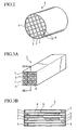
- Fig. 2 shows an example of an appearance of a honeycomb structure 1 used in this embodiment of the present invention.
- the honeycomb structure 1 is obtained in the following manner.
- a plurality of honeycomb segments 2 are bonded with one another by use of bonding layers of an adhesive agent 9, and thus a honeycomb segment assembly is fabricated.
- the honeycomb segment assembly thus fabricated is ground, and is worked out, in a way that the honeycomb segment assembly has a rounded, elliptic, triangular, or another cross section.
- the periphery of the honeycomb segment assembly is coated with a coating material layer 4.
- Each honeycomb segment 2 has a large number of channels 5 which are partitioned from one another by porous partition walls 6, as shown in Figs. 3A and 3B .
- Each of the channels 5 penetrates through the honeycomb segment 2 in a uniaxial direction. Abutting channels 5 are blocked at alternate ends by use of a filler 7. In other words, a channel 5 is opened at the left end, and is blocked at the right end by use of the filler 7. Another channel 5 abutting on this channel is blocked at the left end by use of the filler 7, and is opened at the right end.
- honeycomb structure 1 is fabricated with such a structure, in a case where the honeycomb structure 1 is used as a DPF, exhaust gas flows into a channel which is opened at the left end, and passes through the porous partition walls 6 into the abutting channels, thereafter flowing out of the abutting channels, as shown by arrows in Fig. 3B . While the exhaust gas is passing through the partition walls 6, particulates in the exhaust gas are captured by the partition walls 6. Thus, the exhaust gas can be cleaned.
- the honeycomb segment 2 shown in Fig. 3A has a square cross section.
- the honeycomb segment 2 can have a polygonal cross section, such as a triangular or hexagonal cross section, depending on the necessity.
- the cross section of each of the channels 5 can be triangular, hexagonal, circular, elliptic, or other.
- a material of the honeycomb segments 2 be a material to be obtained by combining at least one selected from a group consisting of cordierite, mullite, alumina, spinel, silicon carbide, silicon carbide-cordierite containing composite, silicon-silicon carbide composite, silicon nitride, lithium aluminum silicate, aluminum titanate, Fe-Cr-Al containing metal.
- a material of the honeycomb segments 2 be silicon carbide or silicon-silicon carbide composite.
- the honeycomb segments 2 can be fabricated in the following manner. A binder, a surfactant, water and the like are added to a material selected from the aforementioned group, and thus a plastic ceramic body material is obtained.
- the binder is methyl cellulose, hydroxypropoxyl cellulose, hydroxyethyl cellulose, carboxymethyl cellulose, polyvinyl alcohol, or the like.
- This ceramic body material is extruded into a honeycomb having a large number of channels 5, which are partitioned from one another by the partitions walls 6, and which penetrate through the honeycomb in a uniaxial direction.
- the honeycomb thus fabricated is dried by use of microwaves, heated air or the like. Thereafter, the honeycomb thus dried is sintered.
- the honeycomb segment 2 is fabricated.
- the channels 5 be blocked at their respective openings by use of the filler 7. It is more advantageous that the channels 5 be blocked at alternate ends, thus looking like checkers.
- the channels can be blocked by use of the filler 7 in the following manner.
- the end surfaces of the honeycomb segment 2 are covered with a resin film.
- a laser beam is irradiated onto the ends of channels 5 which are intended to be blocked while leaving channels 5, which are intended not to be blocked, as they are.
- the channels 5 which are intended to be blocked are opened at their ends.
- the filler in the form of slurry is injected into the channels 5 which are opened at their ends. After this injection, the honeycomb segment is dried and baked.
- the channels are blocked by use of the filler 7.
- a material similar to that used as the honeycomb segment 2 can be used as the filler 7.
- the material of the honeycomb segment 2 is used as a material of the adhesive agent 9, by use of which the honeycomb segments 2 are bonded with one another.
- a material whose chief component is ceramics is suitable as the adhesive agent 9.
- a material which is obtained by adding a metal in the form of metal fibers or the like, a pore-forming material, various ceramics particles and the like, depending on the necessity, to a mixture of inorganic particles or fibers of silicon carbide, silicon nitride, cordierite, aluminum, mullite or the like with a colloidal sol of colloidal silica, colloidal alumina or the like can be selected.
- a coefficient of thermal conductivity of the adhesive agent 9 be 0 .1W/m ⁇ K to 5W/m ⁇ K. It is more advantageous that the coefficient of thermal conductivity of the adhesive agent 9 be 0.2 W/m ⁇ K to 3W/m ⁇ K. In a case where the coefficient of thermal conductivity of the adhesive agent 9 is smaller than 0.1W/m ⁇ K, heat conduction among the honeycomb segments 2 is hindered, and accordingly the temperature inside the honeycomb structure is uneven. For this reason, the coefficient of thermal conductivity which is smaller than 0.1W/m ⁇ K is disadvantageous. On the other hand, in a case where the coefficient of thermal conductivity exceeds 5W/m ⁇ K, the bonding strength is decreased. In addition, this makes it difficult to manufacture the honeycomb structure.
- a coefficient of thermal expansion of the adhesive agent 9 be relatively small from a viewpoint of necessity of preventing a crack from occurring due to a thermal shock. For this reason, it is advantageous that the coefficient of thermal expansion of the adhesive agent 9 be in a range of 1 ⁇ 10 -6 /°C to 8 ⁇ 10 -6 /°C. It is more advantageous that the coefficient of thermal expansion of the adhesive agent 9 be in a range of 1.5 ⁇ 10 -6 /°C to 7 ⁇ 10 -6 /°C. It is the most advantageous that the coefficient of thermal expansion of the adhesive agent 9 be in a range of 2 ⁇ 10 -6 /°C to 6 ⁇ 10 -6 /°C.
- the honeycomb structure 1 is manufactured in the following manner.
- a plurality of honeycomb segments 2 are placed in arrays, and are fitted to one another.
- the adhesive agent 9 is applied to the plurality of honeycomb segments 2 in accordance with below-mentioned pattern conditions with which the honeycomb segments are arrayed. In other words, the adhesive agent 9 is applied to a side surface (side surfaces) of each of the plurality of honeycomb segments 2.
- the plurality of honeycomb segments 2 thus fitted are pressed against one another, and thus are assembled. Thereby, a tentative honeycomb segment assembly is formed. No specific restriction is imposed on a force with which the honeycomb segments are pressed against one another.
- honeycomb segments be pressed against one another with a pressing force of approximately 0.3kgf/cm 2 to 3kgf/cm 2 . It is more advantageous that the honeycomb segments be pressed against one another with a pressing force of approximately 0.5kgf/cm 2 to 2kgf/cm 2 .
- abutting honeycomb segments 2 are bonded with one another with the adhesive agent 9 interposed between each two abutting honeycomb segments.
- the tentative honeycomb segment assembly is heated in a drying chamber.
- the adhesive agent 9 is dried and solidified.
- the tentative honeycomb segment assembly can be heated at a temperature of 50°C to 150°C.
- the honeycomb segment assembly in which the honeycomb segments are firmly bonded with one another is fabricated.
- This honeycomb segment assembly thus fabricated is ground, and is worked out, in a way that the honeycomb segment assembly has a circular, elliptic, triangular, or another cross section.
- the periphery of the honeycomb segment assembly is coated with the coating material layer 4.
- the honeycomb structure 1 is manufactured.
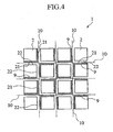
- Fig. 4 shows an embodiment as an example of bonding the honeycomb segments 2. It should be noted that an illustration of the channels inside each of the honeycomb segments 2 is omitted for convenient purposes in Fig. 4 .
- the plurality of honeycomb segments 2 are molded so that the honeycomb segments have the respective square cross sections which are of the same size.
- Each of the honeycomb segments 2 is bonded with the abutting honeycomb segments with the adhesive agent 9 interposed between the honeycomb segment and any of the abutting honeycomb segments.
- the adhesive agent 9 is applied to an external surface(s) (a side surface(s)) of each of the honeycomb segments 2.
- a surface of each of the honeycomb segments 2 to which the adhesive agent 9 is applied is defined as an adhesive agent-applied surface 21, and a surface of each of the honeycomb segments to which no adhesive agent 9 is applied is defined as an adhesive agent-unapplied surface 22.
- reference numeral 10 denotes the bonded line joining the bonded surfaces respectively of the honeycomb segments 2.
- adhesive agent-applied surfaces 21 and adhesive agent-unapplied surfaces 22 are arrayed alternately along the bonded line 10.
- the bonded surfaces respectively of the honeycomb segments 2, which bonded surfaces face the bonded line 10 are arranged in alternations of the adhesive agent-applied surface 21, the adhesive agent-unapplied surface 22, the adhesive agent-applied surface 21 and the adhesive agent-unapplied surface 22 in order from left to right.
- the bonded surfaces respectively of the honeycomb segments 2, which bonded surfaces face the bonded line 10 are arranged in alternations of the adhesive agent-unapplied surface 22, the adhesive agent-applied surface 21, the adhesive agent-unapplied surface 22, and the adhesive agent-applied surface 21 in order from left to right.
- no adhesive agent-applied surfaces 21 are arranged side by side consecutively in the clusters of honeycomb segments along the uppermost bonded line 10. No adhesive agent-unapplied surface 22, either.
- the bonded surfaces respectively of the honeycomb segments 2, which bonded surfaces face the bonded line 10 are arranged in alternations of the adhesive agent-applied surface 21, the adhesive agent-unapplied surface 22, the adhesive agent-applied surface 21 and the adhesive agent-unapplied surface 22 in order from top to bottom.
- the bonded surfaces respectively of the honeycomb segments 2, which bonded surfaces face the bonded line 10 are arranged in alternations of the adhesive agent-unapplied surface 22, the adhesive agent-applied surface 21, the adhesive agent-unapplied surface 22, and the adhesive agent-applied surface 21 in order from top to bottom.
- no adhesive agent-applied surfaces 21 are vertically stacked one on top of another consecutively in the clusters of honeycomb segments along the uppermost bonded line 10, either.
- the adhesive agent-applied surfaces 21 and the adhesive agent-unapplied surfaces 22 are arrayed alternately along the bonded lines 10 running in the horizontal and vertical directions. If the adhesive agent-applied surfaces 21 and the adhesive agent-unapplied surfaces 22 are arrayed alternately along the bonded lines 10 in this manner, neither a surface with the adhesive agent continuously applied thereto nor a surface with no adhesive agent continuously applied thereto occurs on the two sides of any of the bonded lines 10. Accordingly, moisture moving from the adhesive agent 9 on one side of any of the bonded lines 10 is equal to moisture moving from the adhesive agent 9 on the other side of the bonded line 10. This makes the strength on one side of the bonded line 10 equal to the strength on the other side of the bonded line 10. This can prevent a crack from occurring. Hence, this makes it possible to satisfactorily inhibit a crack from developing into the honeycomb structure which is obtained by bonding the honeycomb segments.
- the adhesive agent-applied surface 21 of one honeycomb segment 2 and the adhesive agent-unapplied surface 22 of the other honeycomb segment 2 are fitted to each other.
- the two honeycomb segments 2 are bonded with each other while adhesive agent-applied surface 21 and the adhesive agent-unapplied surface 22 respectively of the honeycomb segments 2 are being fitted to each other.
- the adhesive agent-applied surface 21 of the most left honeycomb segment 2 in the uppermost row and the adhesive agent-unapplied surface 22 of the honeycomb segment 2 abutting on the most left honeycomb segment 2 on the right side are fitted, face-to-face, to each other.
- the adhesive agent-applied surface 21 of one of any two abutting honeycomb segments 2 and the adhesive agent-unapplied surface 22 of the other honeycomb segment 2 are fitted to each other in this manner, the adhesive agent 9 between each two clusters of honeycomb segments, which are arrayed side by side in rows, or which are stacked one on top of another columns, can be even in thickness. Accordingly, the honeycomb structure can be even as a whole. In addition, this makes it possible to alternately array the adhesive agent-applied surfaces 21 and the adhesive agent-unapplied surfaces 22 with ease.
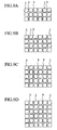
- Examples 1 to 3 respectively representing three different ways how the honeycomb segments are bonded.
- Figs. 6 to 11F respectively show patterns in which a predetermined number of honeycomb segments 2a shown in Fig. 5A , a predetermined number of honeycomb segments 2b shown in Fig. 5B and the adhesive agent 9 are arrayed in the direction which cross-sections the honeycomb structure.
- the adhesive agent is applied to a pair of side surfaces opposite to each other, and the cross section is square.
- the adhesive agent is applied to only one side surface, and the cross section is square.
- honeycomb segments 2a and the honeycomb segments 2b are arrayed in a way that the adhesive agent-applied surfaces 21 and the adhesive agent-unapplied surfaces 22 are arranged alternately along the bonded lines 10 each joining the bonded surfaces respectively of the honeycomb segments 2.
- Fig. 6 shows a pattern in which the honeycomb segments are arrayed in 3 rows ⁇ 3 columns.
- Fig. 7A shows a pattern in which the honeycomb segments are arrayed in 3 rows ⁇ 4 columns.
- Fig. 7B shows a pattern in which the honeycomb segments are arrayed in 4 rows ⁇ 4 columns.
- Fig. 8A shows a pattern in which the honeycomb segments are arrayed in 3 rows ⁇ 5 columns.
- Fig. 8B shows a pattern in which the honeycomb segments are arrayed in 4 rows ⁇ 5 columns.
- Fig. 8C shows a pattern in which the honeycomb segments are arrayed in 5 rows ⁇ 5 columns.
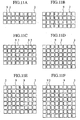
- Fig. 9A shows a pattern in which the honeycomb segments are arrayed in 3 rows ⁇ 6 columns.
- FIG. 9B shows a pattern in which the honeycomb segments are arrayed in 4 rows ⁇ 6 columns.
- Fig. 9C shows a pattern in which the honeycomb segments are arrayed in 5 rows ⁇ 6 columns.
- Fig. 9D shows a pattern in which the honeycomb segments are arrayed in 6 rows ⁇ 6 columns.
- Fig. 10A shows a pattern in which the honeycomb segments are arrayed in 3 rows ⁇ 7 columns.
- Fig. 10B shows a pattern in which the honeycomb segments are arrayed in 4 rows ⁇ 7 columns.
- Fig. 10C shows a pattern in which the honeycomb segments are arrayed in 5 rows ⁇ 7 columns.
- Fig. 10D shows a pattern in which the honeycomb segments are arrayed in 6 rows ⁇ 7 columns.
- Fig. 10A shows a pattern in which the honeycomb segments are arrayed in 3 rows ⁇ 7 columns.
- Fig. 10B shows a pattern in which the honeycomb segments are arrayed in 4 rows
- FIG. 10E shows a pattern in which the honeycomb segments are arrayed in 7 rows ⁇ 7 columns.
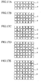
- Fig. 11A shows a pattern in which the honeycomb segments are arrayed in 3 rows ⁇ 8 columns.
- Fig. 11B shows a pattern in which the honeycomb segments are arrayed in 4 rows ⁇ 8 columns.
- Fig. 11C shows a pattern in which the honeycomb segments are arrayed in 5 rows ⁇ 8 columns.
- Fig. 11D shows a pattern in which the honeycomb segments are arrayed in 6 rows ⁇ 8 columns.
- Fig. 11E shows a. pattern in which the honeycomb segments are arrayed in 7 rows ⁇ 8 columns.
- Fig. 11F shows a pattern in which the honeycomb segments are arrayed in 8 rows ⁇ 8 columns.
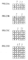
- Figs. 13 to 18F respectively show patterns in which a predetermined number of honeycomb segments 2c shown in Fig. 12A , a predetermined number of honeycomb segments 2b shown in Fig. 12B , a predetermined number of honeycomb segments 2d shown in Fig. 12C and the adhesive agent 9 are arrayed in the cross-section of the honeycomb structure.
- the adhesive agent 9 is applied to two side surfaces abutting on each other, and the cross section is square.
- the adhesive agent 9 is applied to only one side surface, and the cross section is square.
- the adhesive agent 9 is applied to no side surface.
- honeycomb segments 2c, 2b and 2d are arrayed in a way that the adhesive agent-applied surfaces 21 and the adhesive agent-unapplied surfaces 22 are arranged alternately along the bonded lines 10 each joining the bonded surfaces respectively of the honeycomb segments 2 (see Fig. 4 ).
- the numbers of rows and columns in which the honeycomb segments are arrayed in Figs. 13 to 18F corresponds to the numbers of rows and columns in which the honeycomb segments are arrayed in Figs. 6 to 11F .
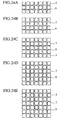
- Figs. 20 to 25F respectively show patterns in which a predetermined number of each of four types of honeycomb segments 2 and the adhesive agent 9 are arrayed in the cross-section of the honeycomb structure.
- the four types of honeycomb segments 2 are honeycomb segments 2e shown in 19A, honeycomb segments 2f shown in 19B, honeycomb segments 2c shown in 19C, and honeycomb segments 2d shown in 19D.
- the cross sections respectively of the honeycomb segments 2 are square.
- the adhesive agent 9 is applied to all of the four side surfaces.
- the adhesive agent 9 is applied to three side surfaces.
- the adhesive agent 9 is applied to two side surfaces abutting on each other.
- the adhesive agent 9 is applied to no side surface.
- the honeycomb segments 2c, 2e, 2f and 2d are arrayed in a way that the adhesive agent-applied surfaces 21 and the adhesive agent-unapplied surfaces 22 are arranged alternately along the bonded lines 10 each joining the bonded surfaces respectively of the honeycomb segments 2 (see Fig. 4 ).
- the numbers of rows and columns in which the honeycomb segments are arrayed in Figs. 20 to 25F correspond to the numbers of rows and columns in which the honeycomb segments are arrayed in Figs. 6 to 11F .
- the adhesive agent-applied surfaces 21 and the adhesive agent-unapplied surfaces 22 are arrayed alternately along the bonded lines 10 each joining the bonded surfaces respectively of the honeycomb segments 2 in the case of each of the array patterns shown in Figs. 6 to 11F , the array patterns shown in Figs. 13 to 18F , and the array patterns shown in Figs. 20 to 25F (see Fig. 4 ).
- neither a surface with the adhesive agent continuously applied thereto nor a surface with no adhesive agent continuously applied thereto occurs on the two sides of any of the bonded lines 10.
- this embodiment can be applied to honeycomb segments each having a triangle, rectangular, hexagonal, or another polygonal cross section, although the application of this embodiment to the honeycomb segments each having the square cross section has been described.
- the adhesive agent-applied surfaces and the adhesive agent-unapplied surfaces are arrayed alternately along any of the bonded lines each joining the bonded surfaces respectively of the honeycomb segments. For this reason, neither a surface with the adhesive agent continuously applied thereto nor a surface with no adhesive agent continuously applied thereto occurs.
- the thickness respectively of the bonded layers can be equal to one another, and thus an even honeycomb structure can be obtained.
- the adhesive agent-applied surface of one honeycomb segment and the adhesive agent-unapplied surface of the abutting honeycomb segment are fitted to, and thereby are bonded with, each other.
- work for arraying the honeycomb segments in a way that no adhesive agent-applied surfaces are arranged side by side and in a way that no adhesive-agent-unapplied surfaces are arranged side by side can be easily carried out.
- a state can be created, where neither a surface with the adhesive agent continuously applied thereto nor a surface with no adhesive agent continuously applied thereto occurs on the sides of any of the bonded lines. This makes it possible to bond the honeycomb segments in a state of no crack occurring.
Landscapes
- Chemical & Material Sciences (AREA)
- Engineering & Computer Science (AREA)
- Physics & Mathematics (AREA)
- Geometry (AREA)
- Chemical Kinetics & Catalysis (AREA)
- Mechanical Engineering (AREA)
- Ceramic Engineering (AREA)
- Combustion & Propulsion (AREA)
- General Engineering & Computer Science (AREA)
- Manufacturing & Machinery (AREA)
- Life Sciences & Earth Sciences (AREA)
- Geology (AREA)
- Materials Engineering (AREA)
- Structural Engineering (AREA)
- Organic Chemistry (AREA)
- Filtering Materials (AREA)
- Ceramic Products (AREA)
- Filtering Of Dispersed Particles In Gases (AREA)
- Processes For Solid Components From Exhaust (AREA)
- Laminated Bodies (AREA)
Priority Applications (1)
| Application Number | Priority Date | Filing Date | Title |
|---|---|---|---|
| PL04732502T PL1666435T3 (pl) | 2003-05-12 | 2004-05-12 | Sposób wytwarzania struktury typu plaster miodu |
Applications Claiming Priority (2)
| Application Number | Priority Date | Filing Date | Title |
|---|---|---|---|
| JP2003133630A JP4408203B2 (ja) | 2003-05-12 | 2003-05-12 | ハニカム構造体の製造方法 |
| PCT/JP2004/006715 WO2004099103A1 (ja) | 2003-05-12 | 2004-05-12 | ハニカム構造体及びその製造方法 |
Publications (3)
| Publication Number | Publication Date |
|---|---|
| EP1666435A1 EP1666435A1 (en) | 2006-06-07 |
| EP1666435A4 EP1666435A4 (en) | 2007-08-29 |
| EP1666435B1 true EP1666435B1 (en) | 2013-07-10 |
Family
ID=33432196
Family Applications (1)
| Application Number | Title | Priority Date | Filing Date |
|---|---|---|---|
| EP04732502.2A Expired - Lifetime EP1666435B1 (en) | 2003-05-12 | 2004-05-12 | Method of manufacturing a honeycomb structure |
Country Status (6)
| Country | Link |
|---|---|
| US (1) | US7666488B2 (pl) |
| EP (1) | EP1666435B1 (pl) |
| JP (1) | JP4408203B2 (pl) |
| KR (1) | KR20060017786A (pl) |
| PL (1) | PL1666435T3 (pl) |
| WO (1) | WO2004099103A1 (pl) |
Families Citing this family (7)
| Publication number | Priority date | Publication date | Assignee | Title |
|---|---|---|---|---|
| JPWO2006035823A1 (ja) * | 2004-09-30 | 2008-05-15 | イビデン株式会社 | ハニカム構造体 |
| WO2007069674A1 (ja) * | 2005-12-14 | 2007-06-21 | Ngk Insulators, Ltd. | 接合材とその製造方法、及びそれを用いたハニカム構造体 |
| JP5478896B2 (ja) * | 2007-01-18 | 2014-04-23 | 日本碍子株式会社 | ハニカムセグメント接合体の製造方法 |
| WO2009118813A1 (ja) * | 2008-03-24 | 2009-10-01 | イビデン株式会社 | ハニカム構造体及びハニカム構造体の製造方法 |
| JP6285234B2 (ja) * | 2014-03-25 | 2018-02-28 | 日本碍子株式会社 | ハニカム構造体の製造方法 |
| CN106762038A (zh) * | 2016-12-13 | 2017-05-31 | 大连凯泓科技有限公司 | 一种过滤器用过滤元件 |
| WO2021166297A1 (ja) | 2020-02-20 | 2021-08-26 | 日本碍子株式会社 | ハニカム構造体 |
Family Cites Families (5)
| Publication number | Priority date | Publication date | Assignee | Title |
|---|---|---|---|---|
| US3887418A (en) * | 1973-05-14 | 1975-06-03 | Peter J Jurisich | Honeycomb product and process for manufacture |
| JP3971027B2 (ja) | 1998-06-25 | 2007-09-05 | イビデン株式会社 | セラミックス構造体の接合装置及び接合方法 |
| JP4409657B2 (ja) * | 1999-03-30 | 2010-02-03 | イビデン株式会社 | フィルタの製造方法 |
| JP4511065B2 (ja) * | 2000-06-05 | 2010-07-28 | 日本碍子株式会社 | ハニカム構造体とハニカムフィルター、及びそれらの製造方法 |
| JP2002219317A (ja) | 2001-01-26 | 2002-08-06 | Ibiden Co Ltd | セラミック構造体の製造方法 |
-
2003
- 2003-05-12 JP JP2003133630A patent/JP4408203B2/ja not_active Expired - Lifetime
-
2004
- 2004-05-12 US US10/556,568 patent/US7666488B2/en not_active Expired - Lifetime
- 2004-05-12 KR KR1020057021566A patent/KR20060017786A/ko not_active Abandoned
- 2004-05-12 PL PL04732502T patent/PL1666435T3/pl unknown
- 2004-05-12 EP EP04732502.2A patent/EP1666435B1/en not_active Expired - Lifetime
- 2004-05-12 WO PCT/JP2004/006715 patent/WO2004099103A1/ja not_active Ceased
Also Published As
| Publication number | Publication date |
|---|---|
| JP2004331485A (ja) | 2004-11-25 |
| EP1666435A1 (en) | 2006-06-07 |
| US20070092691A1 (en) | 2007-04-26 |
| WO2004099103A1 (ja) | 2004-11-18 |
| JP4408203B2 (ja) | 2010-02-03 |
| US7666488B2 (en) | 2010-02-23 |
| EP1666435A4 (en) | 2007-08-29 |
| PL1666435T3 (pl) | 2013-12-31 |
| KR20060017786A (ko) | 2006-02-27 |
Similar Documents
| Publication | Publication Date | Title |
|---|---|---|
| EP2130575B1 (en) | Honeycomb filter comprising segments | |
| US7169203B2 (en) | Honeycomb structure | |
| EP1470852B1 (en) | Honeycomb structure and method of manufacturing the same | |
| EP1698604A1 (en) | Ceramic structure body, device for producing ceramic structure body, and method for producing ceramic structure body | |
| US7384442B2 (en) | Ceramic wall-flow filter including heat absorbing elements and methods of manufacturing same | |
| EP1839725B1 (en) | Honeycomb structure | |
| WO2003011427A1 (en) | Honeycomb structural body and method of manufacturing the structural body | |
| KR101025849B1 (ko) | 허니컴 구조체 | |
| EP2130574A1 (en) | Honeycomb filter | |
| EP3576862B1 (en) | Pattern-plugged honeycomb bodies | |
| JP5378994B2 (ja) | ハニカムセグメント成形用口金、及びハニカム構造体の製造方法 | |
| EP1666435B1 (en) | Method of manufacturing a honeycomb structure | |
| JP5292282B2 (ja) | ハニカムセグメント及びハニカム構造体 | |
| PL206346B1 (pl) | Bryła o strukturze plastra miodu i sposób wytwarzania bryły o strukturze plastra miodu | |
| EP1726800B1 (en) | Honeycomb structure | |
| JP7068453B2 (ja) | 高灰ストレージの、パターンで塞がれるハニカム体及びパティキュレートフィルタ | |
| EP1790408B1 (en) | Honeycomb structure | |
| US20080209893A1 (en) | Exhaust aftertreatment system having a diesel particulate filter manufactured for reducing thermal gradients | |
| US7438966B2 (en) | Honeycomb segment and honeycomb structure using the honeycomb segment | |
| WO2023171539A1 (ja) | 炭化珪素系ハニカムフィルタ |
Legal Events
| Date | Code | Title | Description |
|---|---|---|---|
| PUAI | Public reference made under article 153(3) epc to a published international application that has entered the european phase |
Free format text: ORIGINAL CODE: 0009012 |
|
| 17P | Request for examination filed |
Effective date: 20051201 |
|
| AK | Designated contracting states |
Kind code of ref document: A1 Designated state(s): DE FR PL |
|
| DAX | Request for extension of the european patent (deleted) | ||
| RBV | Designated contracting states (corrected) |
Designated state(s): DE FR PL |
|
| A4 | Supplementary search report drawn up and despatched |
Effective date: 20070731 |
|
| 17Q | First examination report despatched |
Effective date: 20091223 |
|
| GRAP | Despatch of communication of intention to grant a patent |
Free format text: ORIGINAL CODE: EPIDOSNIGR1 |
|
| GRAS | Grant fee paid |
Free format text: ORIGINAL CODE: EPIDOSNIGR3 |
|
| GRAA | (expected) grant |
Free format text: ORIGINAL CODE: 0009210 |
|
| AK | Designated contracting states |
Kind code of ref document: B1 Designated state(s): DE FR PL |
|
| REG | Reference to a national code |
Ref country code: DE Ref legal event code: R096 Ref document number: 602004042670 Country of ref document: DE Effective date: 20130905 |
|
| REG | Reference to a national code |
Ref country code: PL Ref legal event code: T3 |
|
| PLBE | No opposition filed within time limit |
Free format text: ORIGINAL CODE: 0009261 |
|
| STAA | Information on the status of an ep patent application or granted ep patent |
Free format text: STATUS: NO OPPOSITION FILED WITHIN TIME LIMIT |
|
| 26N | No opposition filed |
Effective date: 20140411 |
|
| REG | Reference to a national code |
Ref country code: DE Ref legal event code: R097 Ref document number: 602004042670 Country of ref document: DE Effective date: 20140411 |
|
| REG | Reference to a national code |
Ref country code: FR Ref legal event code: PLFP Year of fee payment: 13 |
|
| REG | Reference to a national code |
Ref country code: FR Ref legal event code: PLFP Year of fee payment: 14 |
|
| REG | Reference to a national code |
Ref country code: FR Ref legal event code: PLFP Year of fee payment: 15 |
|
| REG | Reference to a national code |
Ref country code: FR Ref legal event code: PLFP Year of fee payment: 20 |
|
| PGFP | Annual fee paid to national office [announced via postgrant information from national office to epo] |
Ref country code: PL Payment date: 20230329 Year of fee payment: 20 |
|
| PGFP | Annual fee paid to national office [announced via postgrant information from national office to epo] |
Ref country code: FR Payment date: 20230411 Year of fee payment: 20 Ref country code: DE Payment date: 20230331 Year of fee payment: 20 |
|
| REG | Reference to a national code |
Ref country code: DE Ref legal event code: R071 Ref document number: 602004042670 Country of ref document: DE |