EP1663759B1 - Contenant de transport - Google Patents
Contenant de transport Download PDFInfo
- Publication number
- EP1663759B1 EP1663759B1 EP04762404A EP04762404A EP1663759B1 EP 1663759 B1 EP1663759 B1 EP 1663759B1 EP 04762404 A EP04762404 A EP 04762404A EP 04762404 A EP04762404 A EP 04762404A EP 1663759 B1 EP1663759 B1 EP 1663759B1
- Authority
- EP
- European Patent Office
- Prior art keywords
- chassis
- transport container
- base body
- receiving region
- plastic
- Prior art date
- Legal status (The legal status is an assumption and is not a legal conclusion. Google has not performed a legal analysis and makes no representation as to the accuracy of the status listed.)
- Expired - Lifetime
Links
Images

Classifications
-
- B—PERFORMING OPERATIONS; TRANSPORTING
- B62—LAND VEHICLES FOR TRAVELLING OTHERWISE THAN ON RAILS
- B62B—HAND-PROPELLED VEHICLES, e.g. HAND CARTS OR PERAMBULATORS; SLEDGES
- B62B3/00—Hand carts having more than one axis carrying transport wheels; Steering devices therefor; Equipment therefor
- B62B3/14—Hand carts having more than one axis carrying transport wheels; Steering devices therefor; Equipment therefor characterised by provisions for nesting or stacking, e.g. shopping trolleys
- B62B3/18—Hand carts having more than one axis carrying transport wheels; Steering devices therefor; Equipment therefor characterised by provisions for nesting or stacking, e.g. shopping trolleys nestable by means of pivoted supports or support parts, e.g. baskets
- B62B3/184—Nestable roll containers
- B62B3/188—Z-shaped when nested
-
- B—PERFORMING OPERATIONS; TRANSPORTING
- B62—LAND VEHICLES FOR TRAVELLING OTHERWISE THAN ON RAILS
- B62B—HAND-PROPELLED VEHICLES, e.g. HAND CARTS OR PERAMBULATORS; SLEDGES
- B62B2501/00—Manufacturing; Constructional features
- B62B2501/06—Materials used
- B62B2501/065—Plastics
-
- B—PERFORMING OPERATIONS; TRANSPORTING
- B62—LAND VEHICLES FOR TRAVELLING OTHERWISE THAN ON RAILS
- B62B—HAND-PROPELLED VEHICLES, e.g. HAND CARTS OR PERAMBULATORS; SLEDGES
- B62B3/00—Hand carts having more than one axis carrying transport wheels; Steering devices therefor; Equipment therefor
- B62B3/14—Hand carts having more than one axis carrying transport wheels; Steering devices therefor; Equipment therefor characterised by provisions for nesting or stacking, e.g. shopping trolleys
- B62B3/1476—Hand carts having more than one axis carrying transport wheels; Steering devices therefor; Equipment therefor characterised by provisions for nesting or stacking, e.g. shopping trolleys the main load support being a platform
Definitions
- the invention relates to a manually movable transport container, with a chassis, with a pivotable about a horizontal axis bottom and with an upwardly extending structure, wherein the chassis has two parallel sides and has a shape that saves a space-saving transport container into a another same transport container then allowed when the floor and parts of the structure are in a non-use position.
- Known transport container of this type have a chassis made of steel, which has either a Z-shaped shape or a trapezoidal plan, the longer parallel side is missing.
- the chassis of this transport container carries a usually made of wire mesh floor and a structure formed of metallic walls, so that in the position of use, a space for receiving goods, cargo and the like is created. Moving the floor and parts of the structure in a non-use position, so can the same transport containers space-saving nesting.
- the upwardly pivotable floor is in the operating position on the chassis.
- the transport containers just described have two disadvantages.
- the first disadvantage is that under heavy load on the product directly on B oden pressure points can form, which are caused by the lattice-shaped structure of the soil.
- the second disadvantage is that the floor builds on the chassis at least with its thickness. Since the heights of said transport containers are standardized and these heights must not be exceeded, is lost due to the thickness of the soil, valuable receiving space for the goods to be transported.
- a container is also known, as for example in the international publication WO 98/24699 is described.
- This has a chassis. At this one is arranged around a horizontal pivotable floor. On chassis are provided for fixing the bottom holder.
- the container has two parallel sides and can be stacked in the same car.
- the chassis is made up of several z-shaped shelves, on which a floor - such as a tray can be inserted.
- the chassis has a base made of plastic and the bottom is also made of plastic, wherein the body has a receiving area in which the soil is in the position of use and that in this position, the storage area of the Floor and portions of the body or the chassis are on a plane to form a common loading surface, for which purpose the receiving area for the bottom is formed as a recess and further wherein the receiving area has gradations.
- the footprint for the goods can be formed completely flat. As a result, it is possible to avoid the above-mentioned pressure points occurring on the lowermost goods.
- the chassis has a base body, which is also made of plastic, can this form a trained as a recess receiving area, the floor in its operating position completely receives. As a result, the floor does not rise upwards and the receiving space intended for the goods is greater at the same standard height of the transport container than in the case of the initially mentioned transport containers belonging to the state of the art.
- the floor is insertable into the chassis, it also proves to be expedient if the shelf of the floor and the upper boundary of the body or the chassis lie on a common horizontal plane. As a result, it is also possible to use sections of the main body or of the chassis as storage space.
- movable by hand transport container 1 uses that appropriate basic form of known mobile.
- Transport containers 1 ago is known.
- the chassis 2 also carries an upwardly extending structure 15, which has at least two pivotable about a respective vertical axis 16 walls 17, which are articulated, for example, to stationary wall sections 18.
- the structure 15 may have a fixed rear wall 19, a door 20 and an upper cover 21. Parts of the structure 15 and the bottom 10 can be converted in a known manner from a position of use in a non-use position, so that the transport container 1 can be inserted to save space in a likewise known manner in a same transport container 1, wherein the chassis 2 is designed in a preferred manner as in below FIG. 2 described.
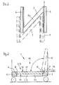
- chassis 2 designed for the transport container 1 chassis 2 has an N- or Z-shaped floor plan, wherein the chassis 2 is further designed so that the chassis 2 of another same transport container 1 in the chassis 2 of the chassis 2 just described can be inserted, see dash-dotted representation.
- the chassis 2 has two parallel sides 4, which are connected by a web 4a. On one of the sides 4, and arranged parallel to this, the horizontal axis 5 is shown, around which the bottom 10 can be moved in a known manner from the horizontal position of use up to the non-use position.
- the chassis 2 may also have an H-shaped floor plan.
- FIG. 3 shows Fig. 3 the chassis 2 of the transport container 1.
- the chassis 2 has an existing plastic base 3, which has a recess 7 formed as receiving area 9, which is formed as a gradation 8 and in which the in-use position, also made of plastic bottom 10 is preferred is positively inserted.
- the receiving area 9 forming gradations 8 are also in FIG. 2 located.
- the gradations 8 are located on the insides of the parallel sides 4. They lie so in mirror image.
- At one of the gradations 8 is the horizontal axis 5, around which the bottom 10 from the drawn position of use upwards in the non-use position (dash-dotted lines) and back is movable.
- the underside 11 of the bottom 10 is also stepped so designed that a positive reception of the bottom 10 in the receiving area 9 is possible.
- the storage area 12 of the floor 10 is located in the example on the same horizontal plane 13 as the two upper portions 6 of the chassis 2 or the body 3. As a result, a common cargo area 14 is formed.
- the main body 3 is to be understood as a component without rollers. Nevertheless, in the base body 3, for example, at least one metallic part which reinforces the base body 3 can be injected.
Landscapes
- Engineering & Computer Science (AREA)
- Chemical & Material Sciences (AREA)
- Combustion & Propulsion (AREA)
- Transportation (AREA)
- Mechanical Engineering (AREA)
- Handcart (AREA)
- Details Of Rigid Or Semi-Rigid Containers (AREA)
- Rigid Containers With Two Or More Constituent Elements (AREA)
Abstract
Claims (5)
- Conteneur de transport (1) mobile manuellement, muni d'un châssis de roulement (2) comprenant un fond (10) pouvant pivoter autour d'un axe horizontal (5), et une superstructure (15) s'étendant vers le haut, ledit châssis de roulement (2) comportant deux faces parallèles (4), et possédant une forme permettant d'insérer ledit conteneur de transport (1) dans un autre conteneur de transport (1) identique, avec économie de place, lorsque le fond (10), ainsi que des parties de la superstructure (15), occupent une position de non-utilisation, caractérisé par le fait que le châssis de roulement (2) offre un corps de base (3) constitué d'une matière plastique, et le fond (10) est semblablement fabriqué en matière plastique, ledit corps de base (3) présentant une zone réceptrice (9) dans laquelle le fond (10) se trouve dans la position d'utilisation ; et par le fait que, dans cette position, le reposoir (12) du fond (10), ainsi que des régions (6) du corps de base (3) ou du châssis de roulement (2), sont situés dans un plan (13) afin de former une surface de chargement (14) commune, la zone réceptrice (9), destinée au fond (10), étant réalisée à cette fin sous la forme d'un renfoncement (7), et ladite zone réceptrice (9) étant par ailleurs pourvue de gradins (8).
- Conteneur de transport selon la revendication 1, caractérisé par le fait que le châssis de roulement (2) présente un profil de base configuré en N, en Z ou en H.
- Conteneur de transport selon la revendication 1, caractérisé par le fait que les gradins (8) se trouvent sur les deux faces parallèles (4) du châssis de roulement (2).
- Conteneur de transport selon la revendication 1, caractérisé par le fait que l'axe horizontal (5) se trouve sur l'un des gradins (8).
- Chariot de transport selon l'une des revendications 1 à 4, caractérisé par le fait que la face inférieure (11) du fond (10) est de configuration en gradin, avec adaptation à la zone réceptrice (9).
Applications Claiming Priority (2)
| Application Number | Priority Date | Filing Date | Title |
|---|---|---|---|
| DE2003134573 DE10334573A1 (de) | 2003-07-28 | 2003-07-28 | Transportcontainer |
| PCT/DE2004/001550 WO2005012060A1 (fr) | 2003-07-28 | 2004-07-16 | Contenant de transport |
Publications (2)
| Publication Number | Publication Date |
|---|---|
| EP1663759A1 EP1663759A1 (fr) | 2006-06-07 |
| EP1663759B1 true EP1663759B1 (fr) | 2009-05-13 |
Family
ID=34088914
Family Applications (1)
| Application Number | Title | Priority Date | Filing Date |
|---|---|---|---|
| EP04762404A Expired - Lifetime EP1663759B1 (fr) | 2003-07-28 | 2004-07-16 | Contenant de transport |
Country Status (6)
| Country | Link |
|---|---|
| EP (1) | EP1663759B1 (fr) |
| CN (1) | CN1809490A (fr) |
| AU (1) | AU2004261341A1 (fr) |
| DE (3) | DE10334573A1 (fr) |
| RU (1) | RU2006106221A (fr) |
| WO (1) | WO2005012060A1 (fr) |
Families Citing this family (4)
| Publication number | Priority date | Publication date | Assignee | Title |
|---|---|---|---|---|
| DE102006050452A1 (de) * | 2006-10-20 | 2008-04-24 | Wanzl Metallwarenfabrik Gmbh | Verkaufscontainer |
| GB0723626D0 (en) * | 2007-12-04 | 2008-01-09 | Haywood Roto Moulding Ltd | A roll container |
| WO2014135270A1 (fr) * | 2013-03-08 | 2014-09-12 | Kesseböhmer Holding e.K. | Conteneur de transport et de vente pliable |
| CN107878531A (zh) * | 2017-11-30 | 2018-04-06 | 苏州艾卡特金属制品有限公司 | 物流台车 |
Family Cites Families (9)
| Publication number | Priority date | Publication date | Assignee | Title |
|---|---|---|---|---|
| DE1990188U (de) * | 1968-07-25 | Werner Cordes 2165 Harsefeld | Transportwagen fur Möbel | |
| DE7318968U (de) * | 1973-08-30 | Gustafsson N | Transportwagen | |
| DE1984447U (de) * | 1968-02-19 | 1968-04-25 | Werner Cordes | Paketwagen. |
| DE2238618A1 (de) * | 1972-08-05 | 1974-02-21 | Werner Cordes | Transportwagen fuer stueckgueter |
| US3953044A (en) * | 1975-03-28 | 1976-04-27 | Banner Metals Division Of Intercole Automation, Inc. | Bulk mail transporter |
| FR2481217A1 (fr) * | 1980-04-23 | 1981-10-30 | Reunis Sa Ateliers | Chariot de manutention repliable, destine a contenir des objets divers |
| US5125520A (en) * | 1991-07-23 | 1992-06-30 | Junzaburo Kawasaki | Tray rack |
| GB9416550D0 (en) * | 1994-08-16 | 1994-10-12 | B Mat Limited | Roll containers |
| FI2836U1 (fi) * | 1996-12-05 | 1997-04-22 | Merikiito Ab Oy | Kuljetushäkki |
-
2003
- 2003-07-28 DE DE2003134573 patent/DE10334573A1/de not_active Withdrawn
-
2004
- 2004-07-16 DE DE112004001885T patent/DE112004001885D2/de not_active Expired - Fee Related
- 2004-07-16 RU RU2006106221/11A patent/RU2006106221A/ru not_active Application Discontinuation
- 2004-07-16 AU AU2004261341A patent/AU2004261341A1/en not_active Abandoned
- 2004-07-16 DE DE502004009488T patent/DE502004009488D1/de not_active Expired - Fee Related
- 2004-07-16 CN CN 200480017177 patent/CN1809490A/zh active Pending
- 2004-07-16 EP EP04762404A patent/EP1663759B1/fr not_active Expired - Lifetime
- 2004-07-16 WO PCT/DE2004/001550 patent/WO2005012060A1/fr not_active Ceased
Also Published As
| Publication number | Publication date |
|---|---|
| CN1809490A (zh) | 2006-07-26 |
| WO2005012060A1 (fr) | 2005-02-10 |
| DE502004009488D1 (de) | 2009-06-25 |
| RU2006106221A (ru) | 2006-07-10 |
| AU2004261341A1 (en) | 2005-02-10 |
| DE112004001885D2 (de) | 2006-06-14 |
| EP1663759A1 (fr) | 2006-06-07 |
| DE10334573A1 (de) | 2005-02-24 |
Similar Documents
| Publication | Publication Date | Title |
|---|---|---|
| AT506371B1 (de) | Entladefahrzeug und kombination eines entladefahrzeuges mit einer behälterabdeckung | |
| DE69809470T2 (de) | Hebevorrichtung mit einer hebbaren und kippbaren plattform | |
| DE8523747U1 (de) | Transportwagen, insbesondere für die Kundschaft in Selbstbedienungsläden | |
| EP0620801A1 (fr) | Pont-grue. | |
| EP0288066A2 (fr) | Récipient à ordures | |
| EP3699058B1 (fr) | Agencement d'un véhicule ferroviaire et dispositif support | |
| DE69214282T2 (de) | Behaeltereinheit fuer abfall | |
| EP1663759B1 (fr) | Contenant de transport | |
| EP0632786A1 (fr) | Recipient stable, notamment une poubelle. | |
| DE19528309C2 (de) | Selbsttragende Kraftfahrzeugkarosserie mit seitlichen Türschwellern | |
| DE102007033147B4 (de) | Stapelbarer Rollbehälter | |
| EP3699057A1 (fr) | Dispositif porteur élevable | |
| DE1431503A1 (de) | Seitenlader mit Hubmast und Lasttraeger | |
| DE1755242C3 (de) | Transportwagen | |
| DE19528309A9 (de) | Selbsttragende Kraftfahrzeugkarosserie mit seitlichen Türschwellern | |
| EP4461671A1 (fr) | Agencement d'étagère | |
| DE19634216C2 (de) | Lastaufnahmemittel zur doppeltiefen Ein- beziehungsweise Auslagerung von palletierten Ladeeinheiten | |
| EP3604072A1 (fr) | Dispositif porteur élevable | |
| EP0508404A1 (fr) | Dispositif de sécurité pour support de transport | |
| EP0877696B1 (fr) | Chariot transporteur a commande manuelle | |
| DE2739291A1 (de) | Transportkarren oder -wagen | |
| DE102020201358A1 (de) | Batteriebetriebenes Fahrzeug, insbesondere Flurförderzeug | |
| EP0798193B1 (fr) | Chariot d'achat emboítable | |
| DE29905790U1 (de) | Fahrzeugeigene Vorrichtung zum Be- und Entladen eines Transportfahrzeugs für mehrere im wesentlichen gleiche Behälter | |
| DE19949968B4 (de) | Vorrichtung zur fahrzeugseitigen Lagerung eines Reserverads für ein Kraftfahrzeug |
Legal Events
| Date | Code | Title | Description |
|---|---|---|---|
| PUAI | Public reference made under article 153(3) epc to a published international application that has entered the european phase |
Free format text: ORIGINAL CODE: 0009012 |
|
| 17P | Request for examination filed |
Effective date: 20050708 |
|
| AK | Designated contracting states |
Kind code of ref document: A1 Designated state(s): DE FR GB IT |
|
| DAX | Request for extension of the european patent (deleted) | ||
| RBV | Designated contracting states (corrected) |
Designated state(s): DE FR GB IT |
|
| 17Q | First examination report despatched |
Effective date: 20080222 |
|
| GRAP | Despatch of communication of intention to grant a patent |
Free format text: ORIGINAL CODE: EPIDOSNIGR1 |
|
| GRAS | Grant fee paid |
Free format text: ORIGINAL CODE: EPIDOSNIGR3 |
|
| GRAA | (expected) grant |
Free format text: ORIGINAL CODE: 0009210 |
|
| AK | Designated contracting states |
Kind code of ref document: B1 Designated state(s): DE FR GB IT |
|
| REG | Reference to a national code |
Ref country code: GB Ref legal event code: FG4D Free format text: NOT ENGLISH |
|
| REF | Corresponds to: |
Ref document number: 502004009488 Country of ref document: DE Date of ref document: 20090625 Kind code of ref document: P |
|
| PGFP | Annual fee paid to national office [announced via postgrant information from national office to epo] |
Ref country code: FR Payment date: 20090720 Year of fee payment: 6 |
|
| PGFP | Annual fee paid to national office [announced via postgrant information from national office to epo] |
Ref country code: DE Payment date: 20090731 Year of fee payment: 6 |
|
| PLBE | No opposition filed within time limit |
Free format text: ORIGINAL CODE: 0009261 |
|
| STAA | Information on the status of an ep patent application or granted ep patent |
Free format text: STATUS: NO OPPOSITION FILED WITHIN TIME LIMIT |
|
| 26N | No opposition filed |
Effective date: 20100216 |
|
| PGFP | Annual fee paid to national office [announced via postgrant information from national office to epo] |
Ref country code: IT Payment date: 20090729 Year of fee payment: 6 |
|
| REG | Reference to a national code |
Ref country code: FR Ref legal event code: ST Effective date: 20110331 |
|
| PG25 | Lapsed in a contracting state [announced via postgrant information from national office to epo] |
Ref country code: DE Free format text: LAPSE BECAUSE OF NON-PAYMENT OF DUE FEES Effective date: 20110201 |
|
| REG | Reference to a national code |
Ref country code: DE Ref legal event code: R119 Ref document number: 502004009488 Country of ref document: DE Effective date: 20110201 |
|
| PG25 | Lapsed in a contracting state [announced via postgrant information from national office to epo] |
Ref country code: FR Free format text: LAPSE BECAUSE OF NON-PAYMENT OF DUE FEES Effective date: 20100802 Ref country code: IT Free format text: LAPSE BECAUSE OF NON-PAYMENT OF DUE FEES Effective date: 20100716 |
|
| PGFP | Annual fee paid to national office [announced via postgrant information from national office to epo] |
Ref country code: GB Payment date: 20120723 Year of fee payment: 9 |
|
| GBPC | Gb: european patent ceased through non-payment of renewal fee |
Effective date: 20130716 |
|
| PG25 | Lapsed in a contracting state [announced via postgrant information from national office to epo] |
Ref country code: GB Free format text: LAPSE BECAUSE OF NON-PAYMENT OF DUE FEES Effective date: 20130716 |