EP1663759B1 - Transport container - Google Patents
Transport container Download PDFInfo
- Publication number
- EP1663759B1 EP1663759B1 EP04762404A EP04762404A EP1663759B1 EP 1663759 B1 EP1663759 B1 EP 1663759B1 EP 04762404 A EP04762404 A EP 04762404A EP 04762404 A EP04762404 A EP 04762404A EP 1663759 B1 EP1663759 B1 EP 1663759B1
- Authority
- EP
- European Patent Office
- Prior art keywords
- chassis
- transport container
- base body
- receiving region
- plastic
- Prior art date
- Legal status (The legal status is an assumption and is not a legal conclusion. Google has not performed a legal analysis and makes no representation as to the accuracy of the status listed.)
- Expired - Lifetime
Links
Images

Classifications
-
- B—PERFORMING OPERATIONS; TRANSPORTING
- B62—LAND VEHICLES FOR TRAVELLING OTHERWISE THAN ON RAILS
- B62B—HAND-PROPELLED VEHICLES, e.g. HAND CARTS OR PERAMBULATORS; SLEDGES
- B62B3/00—Hand carts having more than one axis carrying transport wheels; Steering devices therefor; Equipment therefor
- B62B3/14—Hand carts having more than one axis carrying transport wheels; Steering devices therefor; Equipment therefor characterised by provisions for nesting or stacking, e.g. shopping trolleys
- B62B3/18—Hand carts having more than one axis carrying transport wheels; Steering devices therefor; Equipment therefor characterised by provisions for nesting or stacking, e.g. shopping trolleys nestable by means of pivoted supports or support parts, e.g. baskets
- B62B3/184—Nestable roll containers
- B62B3/188—Z-shaped when nested
-
- B—PERFORMING OPERATIONS; TRANSPORTING
- B62—LAND VEHICLES FOR TRAVELLING OTHERWISE THAN ON RAILS
- B62B—HAND-PROPELLED VEHICLES, e.g. HAND CARTS OR PERAMBULATORS; SLEDGES
- B62B2501/00—Manufacturing; Constructional features
- B62B2501/06—Materials used
- B62B2501/065—Plastics
-
- B—PERFORMING OPERATIONS; TRANSPORTING
- B62—LAND VEHICLES FOR TRAVELLING OTHERWISE THAN ON RAILS
- B62B—HAND-PROPELLED VEHICLES, e.g. HAND CARTS OR PERAMBULATORS; SLEDGES
- B62B3/00—Hand carts having more than one axis carrying transport wheels; Steering devices therefor; Equipment therefor
- B62B3/14—Hand carts having more than one axis carrying transport wheels; Steering devices therefor; Equipment therefor characterised by provisions for nesting or stacking, e.g. shopping trolleys
- B62B3/1476—Hand carts having more than one axis carrying transport wheels; Steering devices therefor; Equipment therefor characterised by provisions for nesting or stacking, e.g. shopping trolleys the main load support being a platform
Definitions
- the invention relates to a manually movable transport container, with a chassis, with a pivotable about a horizontal axis bottom and with an upwardly extending structure, wherein the chassis has two parallel sides and has a shape that saves a space-saving transport container into a another same transport container then allowed when the floor and parts of the structure are in a non-use position.
- Known transport container of this type have a chassis made of steel, which has either a Z-shaped shape or a trapezoidal plan, the longer parallel side is missing.
- the chassis of this transport container carries a usually made of wire mesh floor and a structure formed of metallic walls, so that in the position of use, a space for receiving goods, cargo and the like is created. Moving the floor and parts of the structure in a non-use position, so can the same transport containers space-saving nesting.
- the upwardly pivotable floor is in the operating position on the chassis.
- the transport containers just described have two disadvantages.
- the first disadvantage is that under heavy load on the product directly on B oden pressure points can form, which are caused by the lattice-shaped structure of the soil.
- the second disadvantage is that the floor builds on the chassis at least with its thickness. Since the heights of said transport containers are standardized and these heights must not be exceeded, is lost due to the thickness of the soil, valuable receiving space for the goods to be transported.
- a container is also known, as for example in the international publication WO 98/24699 is described.
- This has a chassis. At this one is arranged around a horizontal pivotable floor. On chassis are provided for fixing the bottom holder.
- the container has two parallel sides and can be stacked in the same car.
- the chassis is made up of several z-shaped shelves, on which a floor - such as a tray can be inserted.
- the chassis has a base made of plastic and the bottom is also made of plastic, wherein the body has a receiving area in which the soil is in the position of use and that in this position, the storage area of the Floor and portions of the body or the chassis are on a plane to form a common loading surface, for which purpose the receiving area for the bottom is formed as a recess and further wherein the receiving area has gradations.
- the footprint for the goods can be formed completely flat. As a result, it is possible to avoid the above-mentioned pressure points occurring on the lowermost goods.
- the chassis has a base body, which is also made of plastic, can this form a trained as a recess receiving area, the floor in its operating position completely receives. As a result, the floor does not rise upwards and the receiving space intended for the goods is greater at the same standard height of the transport container than in the case of the initially mentioned transport containers belonging to the state of the art.
- the floor is insertable into the chassis, it also proves to be expedient if the shelf of the floor and the upper boundary of the body or the chassis lie on a common horizontal plane. As a result, it is also possible to use sections of the main body or of the chassis as storage space.
- movable by hand transport container 1 uses that appropriate basic form of known mobile.
- Transport containers 1 ago is known.
- the chassis 2 also carries an upwardly extending structure 15, which has at least two pivotable about a respective vertical axis 16 walls 17, which are articulated, for example, to stationary wall sections 18.
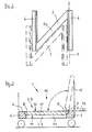
- the structure 15 may have a fixed rear wall 19, a door 20 and an upper cover 21. Parts of the structure 15 and the bottom 10 can be converted in a known manner from a position of use in a non-use position, so that the transport container 1 can be inserted to save space in a likewise known manner in a same transport container 1, wherein the chassis 2 is designed in a preferred manner as in below FIG. 2 described.
- chassis 2 designed for the transport container 1 chassis 2 has an N- or Z-shaped floor plan, wherein the chassis 2 is further designed so that the chassis 2 of another same transport container 1 in the chassis 2 of the chassis 2 just described can be inserted, see dash-dotted representation.
- the chassis 2 has two parallel sides 4, which are connected by a web 4a. On one of the sides 4, and arranged parallel to this, the horizontal axis 5 is shown, around which the bottom 10 can be moved in a known manner from the horizontal position of use up to the non-use position.
- the chassis 2 may also have an H-shaped floor plan.
- FIG. 3 shows Fig. 3 the chassis 2 of the transport container 1.
- the chassis 2 has an existing plastic base 3, which has a recess 7 formed as receiving area 9, which is formed as a gradation 8 and in which the in-use position, also made of plastic bottom 10 is preferred is positively inserted.
- the receiving area 9 forming gradations 8 are also in FIG. 2 located.
- the gradations 8 are located on the insides of the parallel sides 4. They lie so in mirror image.
- At one of the gradations 8 is the horizontal axis 5, around which the bottom 10 from the drawn position of use upwards in the non-use position (dash-dotted lines) and back is movable.
- the underside 11 of the bottom 10 is also stepped so designed that a positive reception of the bottom 10 in the receiving area 9 is possible.
- the storage area 12 of the floor 10 is located in the example on the same horizontal plane 13 as the two upper portions 6 of the chassis 2 or the body 3. As a result, a common cargo area 14 is formed.
- the main body 3 is to be understood as a component without rollers. Nevertheless, in the base body 3, for example, at least one metallic part which reinforces the base body 3 can be injected.
Landscapes
- Engineering & Computer Science (AREA)
- Chemical & Material Sciences (AREA)
- Combustion & Propulsion (AREA)
- Transportation (AREA)
- Mechanical Engineering (AREA)
- Handcart (AREA)
- Details Of Rigid Or Semi-Rigid Containers (AREA)
- Rigid Containers With Two Or More Constituent Elements (AREA)
Abstract
Description
Die Erfindung betrifft einen von Hand bewegbaren Transportcontainer, mit einem Fahrgestell, mit einem um eine horizontale Achse verschwenkbaren Boden und mit einem nach oben sich erstreckenden Aufbau, wobei das Fahrgestell zwei parallele Seiten aufweist und eine Form besitzt, die ein platzsparendes Einschieben des Transportcontainers in einen weiteren gleichen Transportcontainer dann erlaubt, wenn sich der Boden sowie Teile des Aufbaues in einer Nichtgebrauchslage befinden.The invention relates to a manually movable transport container, with a chassis, with a pivotable about a horizontal axis bottom and with an upwardly extending structure, wherein the chassis has two parallel sides and has a shape that saves a space-saving transport container into a another same transport container then allowed when the floor and parts of the structure are in a non-use position.
Bekannte Transportcontainer dieser Art weisen ein aus Stahl gefertigtes Fahrgestell auf, das entweder eine Z-förmige Form oder einen trapezförmigen Grundriss aufweist, dessen längere parallele Seite fehlt. Das Fahrgestell dieser Transportcontainer trägt einen gewöhnlich aus Drahtgitter gefertigten Boden sowie einen aus metallischen Wänden gebildeten Aufbau, so dass in Gebrauchslage ein Raum zur Aufnahme von Ware, Stückgüter und dergleichen geschaffen wird. Bewegt man den Boden sowie Teile des Aufbaues in eine Nichtgebrauchslage, so lassen sich gleiche Transportcontainer platzsparend ineinanderschieben. Der nach oben verschwenkbare Boden liegt in Gebrauchslage auf dem Fahrgestell auf.Known transport container of this type have a chassis made of steel, which has either a Z-shaped shape or a trapezoidal plan, the longer parallel side is missing. The chassis of this transport container carries a usually made of wire mesh floor and a structure formed of metallic walls, so that in the position of use, a space for receiving goods, cargo and the like is created. Moving the floor and parts of the structure in a non-use position, so can the same transport containers space-saving nesting. The upwardly pivotable floor is in the operating position on the chassis.
Die eben beschriebenen Transportcontainer weisen zwei Nachteile auf. Der erste Nachteil besteht darin, dass sich bei schwerer Beladung an der unmittelbar am B oden aufliegenden Ware Druckstellen bilden können, die durch die gitterförmige Struktur des Bodens verursacht werden.The transport containers just described have two disadvantages. The first disadvantage is that under heavy load on the product directly on B oden pressure points can form, which are caused by the lattice-shaped structure of the soil.
Der zweite Nachteil zeigt sich darin, dass der Boden zumindest mit seiner Dicke auf dem Fahrgestell aufbaut. Da die Bauhöhen der genannten Transportcontainer genormt sind und diese Höhen nicht überschritten werden dürfen, geht, bedingt durch die Dicke des Bodens, wertvoller Aufnahmeraum für die zu transportierende Ware verloren.The second disadvantage is that the floor builds on the chassis at least with its thickness. Since the heights of said transport containers are standardized and these heights must not be exceeded, is lost due to the thickness of the soil, valuable receiving space for the goods to be transported.
Aus dem Stand der Technik ist ferner ein Container bekannt, wie er beispielsweise in der internationalen Veröffentlichungsschrift
Weiterhin ist ein stapelbarer Container aus dem
Es ist Aufgabe der Erfindung, einen Transportcontainer der hier vorliegenden Art so weiterzuentwickeln, dass die beiden beschriebenen Nachteile vermieden werden.It is an object of the invention to develop a transport container of the present type so that the two disadvantages described are avoided.
Die Lösung der Aufgabe besteht darin, dass das Fahrgestell einen aus Kunststoff bestehenden Grundkörper aufweist und der Boden ebenfalls aus Kunststoff gefertigt ist, wobei der Grundkörper einen Aufnahmebereich besitzt, in dem sich der Boden in der Gebrauchslage befindet und dass sich in dieser Lage die Abstellfläche des Bodens sowie Abschnitte des Grundkörpers oder des Fahrgestelles auf einer Ebene befinden, um eine gemeinsame Ladefläche zu bilden, wobei hierfür der Aufnahmebereich für den Boden als Vertiefung ausgebildet ist und wobei ferner der Aufnahmebereich Abstufungen aufweist.The solution of the problem is that the chassis has a base made of plastic and the bottom is also made of plastic, wherein the body has a receiving area in which the soil is in the position of use and that in this position, the storage area of the Floor and portions of the body or the chassis are on a plane to form a common loading surface, for which purpose the receiving area for the bottom is formed as a recess and further wherein the receiving area has gradations.
Bei dem aus Kunststoff gefertigten Boden lässt sich die für die Ware bestimmte Stellfläche vollkommen eben ausbilden. Dadurch lassen sich die vorab erwähnten, an der untersten Ware auftretenden Druckstellen vermeiden.In the case of the floor made of plastic, the footprint for the goods can be formed completely flat. As a result, it is possible to avoid the above-mentioned pressure points occurring on the lowermost goods.
Da das Fahrgestell einen Grundkörper aufweist, der ebenfalls aus Kunststoff gefertigt ist, lässt sich an diesem ein als Vertiefung ausgebildeter Aufnahmebereich anformen, der den Boden in dessen Gebrauchslage komplett aufnimmt. Dadurch baut der Boden nach oben nicht auf und der für die Ware bestimmte Aufnahmeraum ist bei gleicher Normhöhe des Transportcontainers größer als bei den eingangs genannten, zum Stand der Technik zählenden Transportcontainern.Since the chassis has a base body, which is also made of plastic, can this form a trained as a recess receiving area, the floor in its operating position completely receives. As a result, the floor does not rise upwards and the receiving space intended for the goods is greater at the same standard height of the transport container than in the case of the initially mentioned transport containers belonging to the state of the art.
Da der Boden in das Fahrgestell einfügbar ist, erweist es sich ebenfalls als zweckmäßig, wenn die Abstellfläche des Bodens und die obere Begrenzung des Grundkörpers oder des Fahrgestelles auf einer gemeinsamen horizontalen Ebene liegen. Dadurch können auch Abschnitte des Grundkörpers bzw. des Fahrgestelles als Abstellfläche genutzt werden.Since the floor is insertable into the chassis, it also proves to be expedient if the shelf of the floor and the upper boundary of the body or the chassis lie on a common horizontal plane. As a result, it is also possible to use sections of the main body or of the chassis as storage space.
Die Erfindung wird anhand von Ausführungsbeispielen näher erläutert. Es zeigt
-
Fig. 1 einen Tranportcontainer; -
Fig. 2 ein "N-förmiges" Fahrgestell sowie -
Fig. 3 im Detail das Fahrgestell entsprechendFig. 2 mit Boden.
-
Fig. 1 a transport container; -
Fig. 2 an "N-shaped" chassis as well -
Fig. 3 in detail the chassis accordinglyFig. 2 with soil.
Der in
Transportcontainern 1 her bekannt ist. So weist der Transportcontainer 1 ein mit Fahrrollen ausgestattetes Fahrgestell 2 auf, das einen um 90° nach oben verschwenkbaren Boden 10 trägt. Das Fahrgestell 2 trägt ferner einen nach oben sich erstreckenden Aufbau 15, der mindestens zwei um je eine vertikale Achse 16 verschwenkbare Wände 17 aufweist, die beispielsweise an ortsfest angeordneten Wandabschnitten 18 angelenkt sind. Der Aufbau 15 kann eine ortsfeste Rückwand 19, eine Türe 20 und eine obere Abdeckung 21 aufweisen. Teile des Aufbaues 15 sowie der Boden 10 lassen sich in bekannter Weise aus einer Gebrauchslage in eine Nichtgebrauchslage überführen, so dass der Transportcontainer 1 in ebenfalls bekannter Weise in einen gleichen Transportcontainer 1 platzsparend eingeschoben werden kann, wobei das Fahrgestell 2 in bevorzugter Weise so gestaltet ist, wie nachfolgend in
Das in
Im Detail und teilweise geschnitten zeigt
Claims (5)
- A manually movable transport container (1), comprising a chassis (2), a bottom (10) which is pivotable about a horizontal axis (5), and an upwardly extending superstructure (15), wherein the chassis (2) has two parallel sides (4) and has a shape which allows the transport container (1) to be pushed into another, identical transport container (1) in a space-saving manner when the bottom (10) and parts of the superstructure (15) are located in a position of non-use, characterised in that the chassis (2) has a base body (3) made of plastic and the bottom (10) is likewise manufactured from plastic, wherein the base body (3) has a receiving region (9) in which the bottom (10) is located in the position of use, and in that in this position the depositing surface (12) of the bottom (10) and portions (6) of the base body (3) or the chassis (2) are arranged in one plane (13) in order to form a common loading surface (14), wherein for this purpose the receiving region (9) for the bottom (10) is formed as a recess (7) and wherein in addition the receiving region (9) has steps (8).
- A transport container according to claim 1, characterised in that the chassis (2) has an N-, Z- or H-shaped contour.
- A transport container according to claim 1, characterised in that the steps (8) are located on the two parallel sides (4) of the chassis (2).
- A transport container according to claim 1, characterised in that the horizontal axis (5) is located on one of the steps (8).
- A transport trolley according to any one of claims 1 to 4, characterised in that the underside (11) of the bottom (10) is stepped in conformity with the receiving region (9).
Applications Claiming Priority (2)
| Application Number | Priority Date | Filing Date | Title |
|---|---|---|---|
| DE2003134573 DE10334573A1 (en) | 2003-07-28 | 2003-07-28 | Shipping containers |
| PCT/DE2004/001550 WO2005012060A1 (en) | 2003-07-28 | 2004-07-16 | Transport container |
Publications (2)
| Publication Number | Publication Date |
|---|---|
| EP1663759A1 EP1663759A1 (en) | 2006-06-07 |
| EP1663759B1 true EP1663759B1 (en) | 2009-05-13 |
Family
ID=34088914
Family Applications (1)
| Application Number | Title | Priority Date | Filing Date |
|---|---|---|---|
| EP04762404A Expired - Lifetime EP1663759B1 (en) | 2003-07-28 | 2004-07-16 | Transport container |
Country Status (6)
| Country | Link |
|---|---|
| EP (1) | EP1663759B1 (en) |
| CN (1) | CN1809490A (en) |
| AU (1) | AU2004261341A1 (en) |
| DE (3) | DE10334573A1 (en) |
| RU (1) | RU2006106221A (en) |
| WO (1) | WO2005012060A1 (en) |
Families Citing this family (4)
| Publication number | Priority date | Publication date | Assignee | Title |
|---|---|---|---|---|
| DE102006050452A1 (en) * | 2006-10-20 | 2008-04-24 | Wanzl Metallwarenfabrik Gmbh | sales containers |
| GB0723626D0 (en) * | 2007-12-04 | 2008-01-09 | Haywood Roto Moulding Ltd | A roll container |
| WO2014135270A1 (en) * | 2013-03-08 | 2014-09-12 | Kesseböhmer Holding e.K. | Collapsible sales and transport container |
| CN107878531A (en) * | 2017-11-30 | 2018-04-06 | 苏州艾卡特金属制品有限公司 | Table trolley |
Family Cites Families (9)
| Publication number | Priority date | Publication date | Assignee | Title |
|---|---|---|---|---|
| DE1990188U (en) * | 1968-07-25 | Werner Cordes 2165 Harsefeld | Transport trolleys for furniture | |
| DE7318968U (en) * | 1973-08-30 | Gustafsson N | Transport trolley | |
| DE1984447U (en) * | 1968-02-19 | 1968-04-25 | Werner Cordes | PACKAGE CART. |
| DE2238618A1 (en) * | 1972-08-05 | 1974-02-21 | Werner Cordes | TRANSPORT TROLLEY FOR STUECKGUETER |
| US3953044A (en) * | 1975-03-28 | 1976-04-27 | Banner Metals Division Of Intercole Automation, Inc. | Bulk mail transporter |
| FR2481217A1 (en) * | 1980-04-23 | 1981-10-30 | Reunis Sa Ateliers | Folding truck for transport - has longerons hinging inwards for nesting after folding of basket panels |
| US5125520A (en) * | 1991-07-23 | 1992-06-30 | Junzaburo Kawasaki | Tray rack |
| GB9416550D0 (en) * | 1994-08-16 | 1994-10-12 | B Mat Limited | Roll containers |
| FI2836U1 (en) * | 1996-12-05 | 1997-04-22 | Merikiito Ab Oy | transport Hedge |
-
2003
- 2003-07-28 DE DE2003134573 patent/DE10334573A1/en not_active Withdrawn
-
2004
- 2004-07-16 DE DE112004001885T patent/DE112004001885D2/en not_active Expired - Fee Related
- 2004-07-16 RU RU2006106221/11A patent/RU2006106221A/en not_active Application Discontinuation
- 2004-07-16 AU AU2004261341A patent/AU2004261341A1/en not_active Abandoned
- 2004-07-16 DE DE502004009488T patent/DE502004009488D1/en not_active Expired - Fee Related
- 2004-07-16 CN CN 200480017177 patent/CN1809490A/en active Pending
- 2004-07-16 EP EP04762404A patent/EP1663759B1/en not_active Expired - Lifetime
- 2004-07-16 WO PCT/DE2004/001550 patent/WO2005012060A1/en not_active Ceased
Also Published As
| Publication number | Publication date |
|---|---|
| CN1809490A (en) | 2006-07-26 |
| WO2005012060A1 (en) | 2005-02-10 |
| DE502004009488D1 (en) | 2009-06-25 |
| RU2006106221A (en) | 2006-07-10 |
| AU2004261341A1 (en) | 2005-02-10 |
| DE112004001885D2 (en) | 2006-06-14 |
| EP1663759A1 (en) | 2006-06-07 |
| DE10334573A1 (en) | 2005-02-24 |
Similar Documents
| Publication | Publication Date | Title |
|---|---|---|
| AT506371B1 (en) | UNLOADING VEHICLE AND COMBINATION OF A UNLOADING VEHICLE WITH A CONTAINER COVER | |
| DE69809470T2 (en) | LIFTING DEVICE WITH A LIFTABLE AND TILTABLE PLATFORM | |
| DE8523747U1 (en) | Transport trolleys, in particular for customers in self-service shops | |
| EP0620801A1 (en) | Gantry crane. | |
| EP0288066A2 (en) | Refuse receptacle | |
| EP3699058B1 (en) | Assembly of a rail vehicle and carrying device | |
| DE69214282T2 (en) | CONTAINER UNIT FOR WASTE | |
| EP1663759B1 (en) | Transport container | |
| EP0632786A1 (en) | Stable container, in particular garbage container. | |
| DE19528309C2 (en) | Self-supporting vehicle body with side sills | |
| DE102007033147B4 (en) | Stackable roll container | |
| EP3699057A1 (en) | Liftable carrying device | |
| DE1431503A1 (en) | Side loader with lifting mast and load carrier | |
| DE1755242C3 (en) | Transport trolley | |
| DE19528309A9 (en) | Self-supporting motor vehicle body with side door sills | |
| EP4461671A1 (en) | Shelf assembly | |
| DE19634216C2 (en) | Load suspension device for double-deep storage or retrieval of palletized loading units | |
| EP3604072A1 (en) | Liftable carrying device | |
| EP0508404A1 (en) | Security device for a transport frame | |
| EP0877696B1 (en) | Manually driven trolley | |
| DE2739291A1 (en) | TRANSPORT CART OR TROLLEY | |
| DE102020201358A1 (en) | Battery-operated vehicles, in particular industrial trucks | |
| EP0798193B1 (en) | Nestable shopping trolley | |
| DE29905790U1 (en) | Vehicle-specific device for loading and unloading a transport vehicle for several essentially identical containers | |
| DE19949968B4 (en) | Device for vehicle-side storage of a spare tire for a motor vehicle |
Legal Events
| Date | Code | Title | Description |
|---|---|---|---|
| PUAI | Public reference made under article 153(3) epc to a published international application that has entered the european phase |
Free format text: ORIGINAL CODE: 0009012 |
|
| 17P | Request for examination filed |
Effective date: 20050708 |
|
| AK | Designated contracting states |
Kind code of ref document: A1 Designated state(s): DE FR GB IT |
|
| DAX | Request for extension of the european patent (deleted) | ||
| RBV | Designated contracting states (corrected) |
Designated state(s): DE FR GB IT |
|
| 17Q | First examination report despatched |
Effective date: 20080222 |
|
| GRAP | Despatch of communication of intention to grant a patent |
Free format text: ORIGINAL CODE: EPIDOSNIGR1 |
|
| GRAS | Grant fee paid |
Free format text: ORIGINAL CODE: EPIDOSNIGR3 |
|
| GRAA | (expected) grant |
Free format text: ORIGINAL CODE: 0009210 |
|
| AK | Designated contracting states |
Kind code of ref document: B1 Designated state(s): DE FR GB IT |
|
| REG | Reference to a national code |
Ref country code: GB Ref legal event code: FG4D Free format text: NOT ENGLISH |
|
| REF | Corresponds to: |
Ref document number: 502004009488 Country of ref document: DE Date of ref document: 20090625 Kind code of ref document: P |
|
| PGFP | Annual fee paid to national office [announced via postgrant information from national office to epo] |
Ref country code: FR Payment date: 20090720 Year of fee payment: 6 |
|
| PGFP | Annual fee paid to national office [announced via postgrant information from national office to epo] |
Ref country code: DE Payment date: 20090731 Year of fee payment: 6 |
|
| PLBE | No opposition filed within time limit |
Free format text: ORIGINAL CODE: 0009261 |
|
| STAA | Information on the status of an ep patent application or granted ep patent |
Free format text: STATUS: NO OPPOSITION FILED WITHIN TIME LIMIT |
|
| 26N | No opposition filed |
Effective date: 20100216 |
|
| PGFP | Annual fee paid to national office [announced via postgrant information from national office to epo] |
Ref country code: IT Payment date: 20090729 Year of fee payment: 6 |
|
| REG | Reference to a national code |
Ref country code: FR Ref legal event code: ST Effective date: 20110331 |
|
| PG25 | Lapsed in a contracting state [announced via postgrant information from national office to epo] |
Ref country code: DE Free format text: LAPSE BECAUSE OF NON-PAYMENT OF DUE FEES Effective date: 20110201 |
|
| REG | Reference to a national code |
Ref country code: DE Ref legal event code: R119 Ref document number: 502004009488 Country of ref document: DE Effective date: 20110201 |
|
| PG25 | Lapsed in a contracting state [announced via postgrant information from national office to epo] |
Ref country code: FR Free format text: LAPSE BECAUSE OF NON-PAYMENT OF DUE FEES Effective date: 20100802 Ref country code: IT Free format text: LAPSE BECAUSE OF NON-PAYMENT OF DUE FEES Effective date: 20100716 |
|
| PGFP | Annual fee paid to national office [announced via postgrant information from national office to epo] |
Ref country code: GB Payment date: 20120723 Year of fee payment: 9 |
|
| GBPC | Gb: european patent ceased through non-payment of renewal fee |
Effective date: 20130716 |
|
| PG25 | Lapsed in a contracting state [announced via postgrant information from national office to epo] |
Ref country code: GB Free format text: LAPSE BECAUSE OF NON-PAYMENT OF DUE FEES Effective date: 20130716 |