EP1663700B1 - Memory-einrichtung für eine schienenlängsführung eines kraftfahrzeugsitzes - Google Patents
Memory-einrichtung für eine schienenlängsführung eines kraftfahrzeugsitzes Download PDFInfo
- Publication number
- EP1663700B1 EP1663700B1 EP04786207A EP04786207A EP1663700B1 EP 1663700 B1 EP1663700 B1 EP 1663700B1 EP 04786207 A EP04786207 A EP 04786207A EP 04786207 A EP04786207 A EP 04786207A EP 1663700 B1 EP1663700 B1 EP 1663700B1
- Authority
- EP
- European Patent Office
- Prior art keywords
- seat
- guide
- memory
- memory device
- locking
- Prior art date
- Legal status (The legal status is an assumption and is not a legal conclusion. Google has not performed a legal analysis and makes no representation as to the accuracy of the status listed.)
- Expired - Lifetime
Links
- 229920003023 plastic Polymers 0.000 claims description 19
- 239000004033 plastic Substances 0.000 claims description 19
- 238000006073 displacement reaction Methods 0.000 claims description 15
- 230000009471 action Effects 0.000 claims description 7
- 239000002184 metal Substances 0.000 claims description 7
- 230000008878 coupling Effects 0.000 claims description 4
- 238000010168 coupling process Methods 0.000 claims description 4
- 238000005859 coupling reaction Methods 0.000 claims description 4
- 230000007246 mechanism Effects 0.000 claims description 4
- 230000006870 function Effects 0.000 description 15
- 230000015572 biosynthetic process Effects 0.000 description 6
- 230000000903 blocking effect Effects 0.000 description 6
- 230000006835 compression Effects 0.000 description 4
- 238000007906 compression Methods 0.000 description 4
- 230000008901 benefit Effects 0.000 description 2
- 230000004048 modification Effects 0.000 description 2
- 238000012986 modification Methods 0.000 description 2
- 229910000639 Spring steel Inorganic materials 0.000 description 1
- 230000004913 activation Effects 0.000 description 1
- 238000005266 casting Methods 0.000 description 1
- 230000008859 change Effects 0.000 description 1
- 150000001875 compounds Chemical class 0.000 description 1
- 230000001419 dependent effect Effects 0.000 description 1
- 230000000694 effects Effects 0.000 description 1
- 125000000524 functional group Chemical group 0.000 description 1
- 230000003993 interaction Effects 0.000 description 1
- 239000003562 lightweight material Substances 0.000 description 1
- 239000000463 material Substances 0.000 description 1
- 230000036316 preload Effects 0.000 description 1
- 230000002028 premature Effects 0.000 description 1
- 230000000284 resting effect Effects 0.000 description 1
- 230000000717 retained effect Effects 0.000 description 1
- 238000007493 shaping process Methods 0.000 description 1
- 239000011343 solid material Substances 0.000 description 1
- 238000003466 welding Methods 0.000 description 1
Images


Classifications
-
- B—PERFORMING OPERATIONS; TRANSPORTING
- B60—VEHICLES IN GENERAL
- B60N—SEATS SPECIALLY ADAPTED FOR VEHICLES; VEHICLE PASSENGER ACCOMMODATION NOT OTHERWISE PROVIDED FOR
- B60N2/00—Seats specially adapted for vehicles; Arrangement or mounting of seats in vehicles
- B60N2/02—Seats specially adapted for vehicles; Arrangement or mounting of seats in vehicles the seat or part thereof being movable, e.g. adjustable
- B60N2/04—Seats specially adapted for vehicles; Arrangement or mounting of seats in vehicles the seat or part thereof being movable, e.g. adjustable the whole seat being movable
- B60N2/06—Seats specially adapted for vehicles; Arrangement or mounting of seats in vehicles the seat or part thereof being movable, e.g. adjustable the whole seat being movable slidable
- B60N2/08—Seats specially adapted for vehicles; Arrangement or mounting of seats in vehicles the seat or part thereof being movable, e.g. adjustable the whole seat being movable slidable characterised by the locking device
- B60N2/0831—Movement of the latch
- B60N2/0862—Movement of the latch sliding
- B60N2/0875—Movement of the latch sliding in a vertical direction
-
- B—PERFORMING OPERATIONS; TRANSPORTING
- B60—VEHICLES IN GENERAL
- B60N—SEATS SPECIALLY ADAPTED FOR VEHICLES; VEHICLE PASSENGER ACCOMMODATION NOT OTHERWISE PROVIDED FOR
- B60N2/00—Seats specially adapted for vehicles; Arrangement or mounting of seats in vehicles
- B60N2/02—Seats specially adapted for vehicles; Arrangement or mounting of seats in vehicles the seat or part thereof being movable, e.g. adjustable
- B60N2/04—Seats specially adapted for vehicles; Arrangement or mounting of seats in vehicles the seat or part thereof being movable, e.g. adjustable the whole seat being movable
- B60N2/06—Seats specially adapted for vehicles; Arrangement or mounting of seats in vehicles the seat or part thereof being movable, e.g. adjustable the whole seat being movable slidable
- B60N2/08—Seats specially adapted for vehicles; Arrangement or mounting of seats in vehicles the seat or part thereof being movable, e.g. adjustable the whole seat being movable slidable characterised by the locking device
- B60N2/0806—Seats specially adapted for vehicles; Arrangement or mounting of seats in vehicles the seat or part thereof being movable, e.g. adjustable the whole seat being movable slidable characterised by the locking device with pin alignment systems, e.g. with at least one of a plurality of locking pins always aligned w.r.t. at least one of a plurality of pin-receiving elements
-
- B—PERFORMING OPERATIONS; TRANSPORTING
- B60—VEHICLES IN GENERAL
- B60N—SEATS SPECIALLY ADAPTED FOR VEHICLES; VEHICLE PASSENGER ACCOMMODATION NOT OTHERWISE PROVIDED FOR
- B60N2/00—Seats specially adapted for vehicles; Arrangement or mounting of seats in vehicles
- B60N2/02—Seats specially adapted for vehicles; Arrangement or mounting of seats in vehicles the seat or part thereof being movable, e.g. adjustable
- B60N2/04—Seats specially adapted for vehicles; Arrangement or mounting of seats in vehicles the seat or part thereof being movable, e.g. adjustable the whole seat being movable
- B60N2/12—Seats specially adapted for vehicles; Arrangement or mounting of seats in vehicles the seat or part thereof being movable, e.g. adjustable the whole seat being movable slidable and tiltable
- B60N2/123—Seats specially adapted for vehicles; Arrangement or mounting of seats in vehicles the seat or part thereof being movable, e.g. adjustable the whole seat being movable slidable and tiltable and provided with memory locks
Definitions
- the invention relates to a memory device for a rail longitudinal guide of a motor vehicle seat according to the preamble of claim 1.
- Such a memory device is provided for use in a rail longitudinal guide having two longitudinally extending, in the extension direction relative to each other displaceable guide rails to adjust the seat longitudinal position of a motor vehicle seat.
- one of the two guide rails is fixed to the vehicle body on the vehicle floor of a motor vehicle arranged and the second, this sliding guide rail serves as a seat rail for receiving a motor vehicle seat.
- the seat longitudinal position of a motor vehicle seat arranged on the second guide rail can thus be adjusted in the rail longitudinal direction.
- Such rail longitudinal guides are usually arranged in pairs on both longitudinal sides of a motor vehicle seat.
- a rail longitudinal guide with a memory device equipped to store certain seat long positions as so-called memory positions the memory device comprises a first memory module, which is displaceably arranged on one of the two guide rails, in particular the body-mounted guide rail, along the direction of extension, in order to be able to set a specific memory position by moving the first memory module. Furthermore, a locking device for locking a previously set memory position is provided on the first memory module.
- This first memory module on the one guide rail is associated with a second memory module on the other, second guide rail (in particular the seat rail) which is fixed there - with respect to the rail longitudinal direction - stationary and has a stop which, upon reaching one of the memory Position corresponding longitudinal seat position of the second guide rail engages with a counter-stop of the first memory module.
- the first memory module allows a movement of the first memory module along a first of the two guide rails (namely, the body-mounted guide rail) a selection of a specific memory position, which is fixable by means of a locking device of the first memory module.
- This memory position corresponds to a certain seat longitudinal position, d. H. a certain position of the two guide rails to each other (in the rail longitudinal direction); and this memory position can be found by a second memory module provided on the second guide rail (seat rail) having a stop which, upon reaching the memory position, engages with an associated counterstop of the first memory module.
- motor vehicle seats with a so-called easy-entry function can be moved forward from a currently set seat longitudinal position with the backrest folded forward in order to facilitate entry into the corresponding motor vehicle behind the forwardly displaced vehicle seat.
- the equipment of a vehicle seat with an easy-entry function is common in the front seats of two-door vehicles.
- the memory device is used in a motor vehicle seat with easy-entry function to set the adjusted before the forward displacement of the vehicle seat with Vorklappter backrest seat longitudinal position, which is for example the preferred Seat long position of the driver is to be able to locate immediately when pushing back the vehicle seat.
- a motor vehicle seat with a memory device for a rail longitudinal guide known which consists of a single movable memory module whose base body is made of plastic.
- the invention is based on the problem of further improving a memory device for a motor vehicle seat of the aforementioned type.
- the second memory module on a plastic base body (preferably in the form of a plastic housing), via which it is attached to the second guide rail.
- the solution according to the invention is based on the recognition that, despite the considerable forces that can act on the second module of the memory device when approaching a memory position, the formation of the main body of the second memory module made of plastic is still possible if the second Memory assembly is designed appropriately, as will become apparent in the explanation of the dependent claims.
- the solution according to the invention has the advantage that the second memory module consists of a lightweight material (plastic), which is also easy to handle in the shaping.
- the base body made of plastic forms so far the basis of the second memory module of the memory device, as the attachment of this module takes place on the associated second guide rail of the rail longitudinal guide on this body.
- the main body of the second memory module has actuating elements and / or actuating surfaces for acting on the locking device of the first memory module.
- the main body can have a guide for an actuating element provided for actuating the locking device of the second module, in particular in the form of a driver.
- this actuating element can form part of a coupling device via which the Locking device of the first memory module is coupled in the manner described above with the backrest of a motor vehicle seat.
- the guide is preferably integrally formed on the base body and is formed for example by a passage opening of the base body, which extends in the guide direction of the corresponding actuating element. Further, the guide may have a cavity for receiving an elastic element, in particular in the form of a helical spring, that exerts a bias on the arranged in or on the guide, movable (sliding) actuator.
- the base body on at least one guide surface along which slides an element of the locking device of the first memory module when approaching the memory position with the backrest folded up, z. B., to prevent premature unlocking of the locking device by the purpose provided actuator of the second memory module.
- the existing plastic base body of the second memory module is preferably formed for a positive attachment to the second guide rail of the rail longitudinal guide.
- the main body integrally molded positive locking elements (locking means) which are formed by at least one expandable snap element, which is so spread apart after locking in an associated latching opening of the second guide rail (optionally using a locking pin) that a positive, optionally additionally non-positively acting, snap connection is made.
- the stop of the second memory module which engages upon reaching the memory position with an associated counter-stop of the first memory module is formed by a separate, of a solid material, namely metal (in particular sheet metal), existing component which is connected to the existing plastic base body of the second memory module.
- the connection is preferably positive and / or non-positive over a large Umgriff.
- the memory device can be combined with a locking device which serves to lock the two guide rails in a previously set seat longitudinal position to a seat assembly, which is mounted on a rail longitudinal guide of a motor vehicle seat and can be combined to form a built-in module, as explained in more detail below will be.
- the locking device comprises movably mounted locking elements, in particular in the form of ratchet teeth, which can be brought to lock the rail longitudinal guide in a previously set seat longitudinal position in a locking position in which they engage in associated locking points.
- the locking elements are regularly elastically biased in the direction of their locking position, so that the vehicle seat is automatically locked in a respectively seated longitudinal position, when the locking elements are not active (eg by folding the backrest or by operating a thus provided actuating lever) from the dotted resting points are dug.
- the locking device is preferably arranged on the longitudinally movable, designed as a seat rail second guide rail, while the associated locking points are provided on the body-mounted first rail or run in a separate latching rail next to this.
- the locking elements For storage of the locking elements to be arranged on at least one bearing plate movable according to a particularly preferred embodiment of the present invention, the locking elements.
- This bearing plate replaces the usual castings for the storage of locking elements.
- At least one of the bearing plates can additionally serve to guide the movably mounted on the main body of the memory device actuating element, for. B. by a guide opening in the form of a passage is formed on the corresponding bearing plate.
- the guidance of the actuating element is additionally stabilized, since it is no longer perceived solely by the existing plastic base body.
- locking elements ratchet teeth which are movable along their extension direction to lock the two guide rails or unlock, so are particularly suitable for their storage in two Displacement direction of the locking elements spaced apart guide plates, which each have guide openings for the locking elements.
- the invention designed according to the second assembly of the memory device on the one hand and the locking device on the other hand are preferably arranged to each other that at least one bearing plate of the locking device, the abutment-forming component of the second memory module is supported such that when approaching the memory position occurring at the stop Forces are not derived in the existing plastic base body of the second memory module, but rather in that bearing plate. Since the bearing plates of the locking device are in turn attached to one of the guide rails, the forces occurring when approaching the memory position are ultimately taken up by the guide rails themselves, which are already designed extremely stable reasons of crash safety and therefore the corresponding forces readily can compensate.
- One of the bearing plates of the locking device also takes on the actuating means which serve to actuate the locking elements of the locking device (against the action of the elastic bias).
- a motor vehicle seat with easy-entry function and a memory device according to the invention is characterized by the features of claim 32.
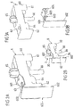
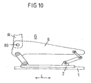
- FIG. 10 shown in a side view seat frame G (seat base) comprises a seat rail 2, which in the seat longitudinal direction L movable on one of the Vehicle body to be fastened (body-mounted) lower rail 1 superimposed, and a seat side part 8, which is articulated via front and rear toggle lever height adjustable on the seat rail 2.
- the seat frame G has a corresponding arrangement. Between the two seat side parts of the seat frame G extends a seat that receives a seat cushion on which a vehicle occupant can take place.
- the side parts 8 of the seat frame G each have a bearing 80 for pivotally mounting a in FIG. 10 dashed lines indicated backrest R on.
- the seat frame in each case all those components which are movable on the body-mounted lower rail 1 in the seat longitudinal direction, ie in particular the seat rail 2, the seat side part 8 and the other associated components of the seat.
- FIGS. 5a to 7 Essential, characteristic features of the in the FIGS. 5a to 7
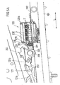
- FIG. 5a is a perspective view formed by two guide rails 101, 102 rail longitudinal guide consisting of a body-mounted to be arranged lower rail 101 and a seat frame supporting the top rail 102.
- This longitudinal guide 101, 102 allows adjustment of the seat longitudinal position (position of the seat frame in the seat longitudinal direction L).
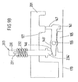
- a locking device 120 is provided with elastically biased locking teeth Z, which is arranged on the seat-side upper rail 102 (seat rail) and whose ratchet teeth Z can engage in associated detent openings of the body-mounted bottom rail to lock the two rails 101, 102 , Due to the elastic preloading of the ratchet teeth Z in the direction of the associated latching openings, the locking device 120 has the tendency to lock the two rails 101, 102 together, provided that they do not act by acting on an actuating element 120b (cf. DE 101 27 152 A1 ) is unlocked. This effect can - as in the DE 101 27 152 A1 set out in detail - done on the one hand by a direct release of the locking device via a suitable operating lever or indirectly by folding the backrest to trigger the easy-entry function.
- a memory device 104, 105, 107 recognizable, namely a slider 105, a pivotally arranged on the slider 105 pawl 104 and provided with latching openings 170 latching rail 107, in which a latching hook 141 of the pawl 104 can engage to lock a previously set memory position. Also in this regard will be explained in more detail on the DE 101 27 152A1 directed.
- FIGS. 5a and 5b a section of the seat frame is shown in a state in which the seat is locked in folded up (located in its use position) backrest by means of the locking device 120 in a memory position.
- an actuating element in the form of a driver 203 such that the pawl 104th is excavated with its latching hook 141 from the locking rail 107.
- the driver 203 is longitudinally displaceable on the seat rail 102 and a holding member 201 attached to the seat rail 102 and includes an elongated body 230, at its lower, the pawl 104 facing the end provided with a driving opening 235 driving element 234 is formed or fixed.
- This driver 203 is biased by means of an elastic element 232 in the form of a compression spring (return spring), which is supported on the one hand on the holding part 201 and on the other hand on a protruding from the main body 230 of the driver 203 projection 231, biased in such a direction away from the pawl 104 in that it has a tendency to lift off the pawl 104.
- a compression spring return spring
- a blocking element 221 on the base body 220 of a pivotally mounted about an axis 225 lever 202 which is biased by a spring element 228 in the form of a torsion spring in the direction of the projection 231 of the driver 203, that the blocking element 221 opposite to the driver the action of the provided on the driver elastic element 232 against the pawl presses, so that the latching hook 141 of the pawl 104 is excavated from the locking rail 107.
- a projection 145 of the pawl 104 designed as a latching nose engages in the driving opening 235 of the driver 203.
- the mechanism is designed such that the locking of the memory device 104, 105, 107 takes place when folding the backrest from a vertical use position by about 20 ° to 40 °.
- the locking of the memory device is thus already in the first stage (phase) of the activation of the easy-entry mechanism by folding the backrest in the direction of the seat.
- the locking device 120 is still locked in this first phase of the folding forward of the backrest, so that no displacement of the seat in the longitudinal direction L can take place.
- an operating portion 222 provided on the pivotally mounted lever 202 acts on an operating lever 109 of the locking device 120, so that the locking device 120 is unlocked. This then allows a displacement of the seat in the longitudinal direction L.
- a displacement of the seat in the longitudinal direction L in a folding forward of the backrest for performing the easy-entry function is only possible after the pawl 104 of the memory device 104, 105, 107 has been locked.
- the existing when folding the backrest memory position is reliably fixed before a shift of the seat can be done with folded backrest.
- This memory position can then be found during the subsequent return of the seat, as in the DE 101 27 152 A1 explained. It is thus prevented that during exercise of the easy-entry function, a displacement of the seat can be done with pre-folded backrest before the starting position of the seat is fixed as a memory position.
- the entire arrangement is due to the displaceability of the driver 203 substantially perpendicular to the extension direction L of the rail longitudinal guide and because of the pivotal mounting of the lever 202 with the blocking element 221 very compact and located substantially in the space enclosed by the rails 101, 102 of the rail longitudinal space or just protrudes upwards out of this.
- the back of the seat folded forward to trigger the easy-entry function so the problem may occur that the latching hook 141 of the pawl 104 can not engage in one of the locking openings 170 of the locking rail 107.
- the locking device 120 usually allows a stepless adjustment of the seat longitudinal position, as compared to those in the DE 299 10 720 U1 described locking device, while in the present case for the locking of the memory position a finely graded (ie no continuous) latching (using the locking rail 107 with latching openings 170) is provided. It may therefore be the case that when folding the backrest of the locking hooks 141 of the pawl 104 can not engage in a latching opening 170, but gets up on the edge. As a result, initially no locking of the memory position is possible.
- the pawl 104 together with the slider 105 is still a bit further entrained in this case because of a folded back the seat rail 102 provided stop 127 acts on an associated pawl side stop 147.
- the pawl 104 and the slider 105 are only taken so far until the latching hook 141 of the pawl 104 can fully engage under the action of the provided on the pawl spring element in the nearest detent opening 170 of the locking rail 107.
- the pawl 104 and thus the locking device 104, 107 of the memory device 104, 105, 107 in total are then locked in that memory position closest to the seat longitudinal position in which the locking device 120 was locked prior to folding the backrest.
- the pawl-side stop 147 In the locking state in which the latching hook 141 of the pawl 104 engages in a latching opening 170 of the latching rail 107, the pawl-side stop 147 is below the seat rail-side stop 127, so that these stops 127, 147 can no longer interact with each other.
- the seat can then be moved further forward in the seat longitudinal direction L, wherein the pawl 104 and the slider 105 remain in the previously locked memory position.
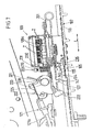
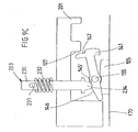
- FIG. 8 is a modification of the invention of the embodiment of the FIGS. 5a to 7 shown, with regard to the approach of the memory position when pushing back the seat with befind Anlagen in use position, so folded up backrest. This is particularly true in the case where the seat is displaced rearward toward the memory position while a vehicle occupant is seated located on the seat.
- the driver 203 hits upon reaching the memory Position on the pawl 104.
- the driver 203 is due to the backrest in use position by means of the blocking element 221 (in FIG. 8 not shown) in the direction of the pawl 104 of the memory device pressed down.
- the pawl 104 has a ramp 146, on which the lower end portion 234 'of the driver 203 to a trough 145th 'can slide the pawl 104.
- This is in the FIGS. 9a to 9c shown, wherein the driver 203 finally engages in the memory position with its lower end portion 234 'in the associated trough 145' of the pawl 104.
- the lower end portion 234 'of the driver 203 and the trough 145' of the pawl 104 then act as stops that allow entrainment of the pawl 104 together with the slider 105 during further displacement of the seat.
- the ramp 146 extends only over a portion of the width of the pawl 104 (extent perpendicular to the seat longitudinal direction L and the direction of movement of the driver 203), so that adjacent portions 148 of the pawl 104 may act as stops to 104 in the locked state of the pawl Define memory position.
- the driver 203 Since the driver 203 is pressed when starting the memory position befindaji in use position, folded back in the direction of the pawl 104 down, it also lifts the latching hook 141 of the pawl 104 from the associated locking rail 107 when approaching the memory position , Only then is the joint further adjustment of the seat on the one hand and by pawl 104 and slider 105 on the other hand allows.
- the driver 203 Since the stops 127, 147 initially prevent pivoting of the pawl 104 and the ramp 147 is inclined in the seat longitudinal direction, the driver 203 is first raised when driving on the ramp 146.
- the spring 203 (by means of the spring 232) mounted driver 203 performs a compensating movement in the vertical direction.
- the driver 203 is under the action of the compression spring 232 in a position in which he can not act on the pawl 104 of the memory device 104, 105, 107.
- the pawl 104 is locked together with the slider 105 in the memory position, in which the seat is then automatically stopped, so that the previously set memory position when pushing back the seat with folded back - as desired - has been recovered.
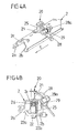
- FIGS. 1a to 4b a development of the known, above with reference to the FIGS. 5a to 10 described arrangements described. It differs based on the FIGS. 1a to 4b to be explained arrangement of the in the FIGS. 5a to 10 shown seat frame, in particular with regard to the formation of the locking device 120 and with respect to the formation of a arranged on the seat rail 102 of the rail longitudinal guide 101, 102 memory module 6, which with the memory device 104, 105, 107 of the in the FIGS. 5a to 9c shown type works together. Only on the above, newly formed components of a motor vehicle seat with easy-entry function and memory device, as previously described with reference to FIGS. 5a to 10 is described in the overview, will be discussed further below.
- FIGS. 1a and 1b and 4a and 4b has a locking device 20, which is for locking a rail longitudinal guide (from the in the FIGS. 4a and 4b only the seat rail 2 can be seen) blocking elements in the form of ratchet teeth 25, which are longitudinally movably mounted on two guide plates 21, 22 of the locking device 20.
- the two guide plates 21, 22 are spaced apart along the direction of movement (displacement direction) of the ratchet teeth 25 and each have passage openings as guide openings for the ratchet teeth 25.
- Each of the ratchet teeth 25 is associated with an elastic element in the form of a coil spring 26 which is supported on the one hand on the respective ratchet 25 and on the other hand on the one guide plate 21 of the locking device 20 so that the ratchet teeth 25 are held substantially rattle-free and are thereby biased in that they engage in associated detent openings in order to fix the longitudinal rail guide (from the one in the FIGS. 4a and 4b only the seat rail 2 can be seen) in a previously set seat longitudinal position to lock.
- a pivotally mounted about an axis extending parallel to the rail longitudinal direction L 28a actuating lever 28 is provided which is biased by means of an elastic element in the form of a torsion spring 29 in the direction of a position in which the ratchet teeth 25 are not lifted out of their locking position.
- a torsion spring 29 also supports the torsion spring 29 (by acting on the operating lever 28), the preload of the ratchet teeth 26 in a position in which the locking device locks the guide rails of the rail longitudinal guide in a previously set seat longitudinal position.
- the two guide plates 21, 22 of the locking device 20 are each arranged on the seat rail 2 and connected thereto.
- an attachment of a bearing plate 21 on the associated seat rail 2 by rivets or screws is possible.
- the other guide plate 22 which is spaced along the direction of extension or displacement of the ratchet teeth 25 from the first guide plate 21, extends from the one angled leg 2a to the other angled leg 2b of the U-shaped seat rail 2 and supported there each with lateral end portions 22a, 22b.
- the connection between the further guide plate 22 and the seat rail 2 is carried out by laser welding at least one lateral end portion 22 b of the corresponding guide plate 22nd
- a special feature of the above based on the FIGS. 1a and 1b and 4a and 4b described locking device is in the formation of the bearing and guide means for the ratchet teeth 25, which is formed by two spaced-apart guide plates 21, 22 - in contrast to the known Weinmetallgussgephaseusen for receiving the ratchet teeth. As a result, the weight and cost of the locking device can be further reduced.
- the movable components (locking device in the form of a pawl 104, slider 105) of the body-mounted rail associated memory device 104, 105, 107 referred to as the first memory module, and it will cooperate hereby acting, arranged on the seat rail 2 elements as the second Memory module called.
- the second memory module 6 comprises a base body 60 made of plastic in the form of a plastic housing, which is to be fastened by means of a snap element 65 on the seat rail 2 of a rail longitudinal guide.
- a snap element 65 on the seat rail 2 of a rail longitudinal guide.
- the preferably integrally formed on the base body 60 snap member 65 is inserted into an associated mounting opening of the seat rail 2 and then spread by means of a locking pin 66 so that it engages behind the corresponding mounting hole form-fitting and preferably also frictionally rests on the edge of the opening.
- a rivet or other suitable fasteners may be used as connecting means.
- a guide surface 61 is formed, (corresponding to the stop 127 from the FIGS. 5b to 9c ) when starting the memory position with the backrest folded up with an associated stop 147 of the pawl 104 of the first memory module 104, 105 can cooperate.
- the base body 60 formed as a passage opening guide 63 in the form of a formed for an actuator 3, which is formed by a driver in the form of a bolt 30 with an actuating head 34 and the action on the pawl 104 of the first memory assembly 104th , 105 as a function of the pivotal position of the backrest of the corresponding vehicle seat is actuated, as described above with reference to FIGS. 5a to 10 already described.
- the actuating element 3 in other ways with the first memory module 104, 105, in particular the pawl 104 cooperate, compare DE 101 27 151 A1 .
- DE 101 27 153 A1 such as DE 202 10 895 A1 ,
- actuating element 3 is mounted on the existing plastic base body 60 of the second memory module 6, which in turn on the seat rail of a Longitudinal rail guide is set, and that this actuating element 3 with a first memory assembly 104, 105, in particular the pawl 104, cooperates, which is assigned to the body-mounted guide rail of a rail longitudinal guide.
- a housing 64 is further integrally formed on the base body 60 made of plastic, in accordance with FIG. 1b an elastic element in the form of a coil spring is captively received, by means of which the actuating element 3 in a certain direction, ie (depending on the intended use in an individual case) in the direction of the pawl 104 of the memory device or in a direction away from the pawl 104 of the Memory device is biased.
- the second memory module 6 further has a stopper 602, which engages upon reaching the memory position with a counter-stop of the first memory module 104, 105 to stop the seat frame upon reaching the memory position.
- the corresponding counter-stop can be formed for example by the pawl 104 of the first memory module.
- the stop 602 forming portion (leg) of the sheet metal part 600 extends along an angled portion 62 of the existing plastic base body 60; and a base surface 601 of the sheet metal part 600 has a through hole 603, which is aligned with the serving for guiding the actuating element 3 through hole 63 of the plastic body 60 existing.
- the actuating element 3 is guided not only in the passage opening 63 of the existing plastic base body 60, but also in a passage 21 a, which is formed on the one, upper bearing plate 21 and which is penetrated by the actuating element 3, in particular compare FIG. 1b ,
- the guide of the actuating element 3 serving passage 21a is formed in the same manner as that of the attachment of a bearing plate 21 on the seat rail 2 serving through holes 21a.
- passages 21a can be attached to the bearing plate 21 in be easily formed by the fact that in the bearing plate 21, a through hole is formed and through this a mandrel is drawn, the outer diameter is greater than the diameter of the previously formed through hole.
- a tubular section designated here as a passage 21a is formed on the bearing plate 21 by displacing material from the edge of the previously formed passage opening to the outside by means of the drawing mandrel and forming a section (passage 21a) protruding in a tubular manner from the bearing plate 21.
- the stop 602 forming portion of the sheet metal part 600 is further supported on the second bearing plate 22 of the locking device 20 from that when starting the memory position on the stop 602 acting forces are introduced directly into the second bearing plate 22 and from there via its support points 22a, 22b can be received by the seat rail 2, cf.
- FIGS. 4a and 4b
Landscapes
- Engineering & Computer Science (AREA)
- Aviation & Aerospace Engineering (AREA)
- Transportation (AREA)
- Mechanical Engineering (AREA)
- Seats For Vehicles (AREA)
Applications Claiming Priority (2)
| Application Number | Priority Date | Filing Date | Title |
|---|---|---|---|
| DE20314237U DE20314237U1 (de) | 2003-09-09 | 2003-09-09 | Memory-Einrichtung für eine Schienenlängsführung eines Kraftfahrzeuges |
| PCT/DE2004/001935 WO2005025927A1 (de) | 2003-09-09 | 2004-08-27 | Memory-einrichtung für eine schienenlängsführung eines kraftfahrzeugsitzes |
Publications (2)
| Publication Number | Publication Date |
|---|---|
| EP1663700A1 EP1663700A1 (de) | 2006-06-07 |
| EP1663700B1 true EP1663700B1 (de) | 2008-06-25 |
Family
ID=34072171
Family Applications (1)
| Application Number | Title | Priority Date | Filing Date |
|---|---|---|---|
| EP04786207A Expired - Lifetime EP1663700B1 (de) | 2003-09-09 | 2004-08-27 | Memory-einrichtung für eine schienenlängsführung eines kraftfahrzeugsitzes |
Country Status (6)
| Country | Link |
|---|---|
| US (1) | US7600816B2 (enExample) |
| EP (1) | EP1663700B1 (enExample) |
| JP (1) | JP4719677B2 (enExample) |
| DE (3) | DE20314237U1 (enExample) |
| ES (1) | ES2308257T3 (enExample) |
| WO (1) | WO2005025927A1 (enExample) |
Cited By (2)
| Publication number | Priority date | Publication date | Assignee | Title |
|---|---|---|---|---|
| CN102785593A (zh) * | 2011-05-17 | 2012-11-21 | 达世株式会社 | 车辆座椅导轨的锁定装置 |
| US10940773B2 (en) | 2015-01-26 | 2021-03-09 | Brose Fahrzeugteile Gmbh & Co. Kommanditgesellschaft, Coburg | Vehicle seat |
Families Citing this family (29)
| Publication number | Priority date | Publication date | Assignee | Title |
|---|---|---|---|---|
| DE202005003626U1 (de) * | 2005-03-02 | 2006-07-13 | Brose Fahrzeugteile Gmbh & Co. Kommanditgesellschaft, Coburg | Feststellvorrichtung für einen einstellbaren Fahrzeugsitz |
| DE102005020696A1 (de) * | 2005-04-28 | 2006-11-02 | Brose Fahrzeugteile Gmbh & Co. Kommanditgesellschaft, Coburg | Verstelleinrichtung für ein Kraftfahrzeug |
| US8029063B2 (en) * | 2006-03-24 | 2011-10-04 | Johnson Controls Technology Company | Vehicle seat track |
| US20080122280A1 (en) * | 2006-09-08 | 2008-05-29 | Ford Global Technologies, Llc | Multifunction vehicular seat |
| DE102007027321A1 (de) * | 2007-06-14 | 2009-02-05 | Brose Fahrzeugteile Gmbh & Co. Kommanditgesellschaft, Coburg | Verriegelungsvorrichtung für ein Schienenverstellsystem |
| JP5080176B2 (ja) * | 2007-08-31 | 2012-11-21 | 富士機工株式会社 | シートスライド装置 |
| DE202009006443U1 (de) * | 2009-05-02 | 2010-09-23 | Paul Hettich Gmbh & Co. Kg | Verbindungsvorrichtung |
| KR101585265B1 (ko) | 2009-11-18 | 2016-01-13 | 주식회사다스 | 차량용 시트레일의 로크장치 |
| JP5509980B2 (ja) * | 2010-03-25 | 2014-06-04 | アイシン精機株式会社 | 車両用シートスライド装置 |
| JP5551486B2 (ja) * | 2010-03-29 | 2014-07-16 | デルタ工業株式会社 | シートのスライドロック装置 |
| US8382057B2 (en) * | 2010-03-31 | 2013-02-26 | Crh North America, Inc. | Low profile seat track system |
| KR101082768B1 (ko) | 2010-05-25 | 2011-11-11 | (주)케이엠앤아이 | 이지 엔트리 메모리 시스템 |
| CN102971181B (zh) * | 2010-05-28 | 2016-04-06 | 布罗泽汽车部件制造科堡有限公司 | 用于汽车座椅的纵向导引装置 |
| KR101136824B1 (ko) * | 2010-07-16 | 2012-04-19 | (주)케이엠앤아이 | 차량용 시트트랙 로킹 시스템 |
| DE102010055244B4 (de) * | 2010-12-20 | 2012-08-30 | Keiper Gmbh & Co. Kg | Längseinstellbarer Fahrzeugsitz |
| DE102011003052A1 (de) * | 2011-01-24 | 2012-07-26 | Brose Fahrzeugteile Gmbh & Co. Kommanditgesellschaft, Coburg | Betätigungsvorrichtung für eine Verriegelungseinrichtung einer Verstellvorrichtung eines Kraftfahrzeugsitzes |
| DE102011014333A1 (de) * | 2011-03-18 | 2012-09-20 | GM Global Technology Operations LLC (n. d. Gesetzen des Staates Delaware) | Arretiervorrichtung, Sitzverfahrvorrichtung, Fahrzeugsitz, Kraftfahrzeug und Verfahren hierzu |
| DE102011100866B4 (de) * | 2011-05-07 | 2020-06-18 | Adient Luxembourg Holding S.À R.L. | Längseinstellbarer Fahrzeugsitz mit Memoryvorrichtung |
| US10266074B2 (en) | 2011-10-17 | 2019-04-23 | Fisher & Company, Incorporated | Seat-track assembly |
| CA3077833C (en) * | 2011-10-17 | 2023-01-03 | Fisher & Company, Incorporated | Seat-track assembly |
| DE102012110208B4 (de) * | 2012-05-30 | 2018-04-19 | Adient Luxembourg Holding S.à.r.l. | Betätigungseinheit für einen Fahrzeugsitz |
| US20140292045A1 (en) * | 2013-03-29 | 2014-10-02 | Daniel Halterman Jeffery | Mechanism for Increasing the Distance Traveled During a Forceful Change in Velocity |
| US10059232B2 (en) | 2014-03-26 | 2018-08-28 | Faurecia Automotive Seating, Llc | Vehicle seat |
| KR101598713B1 (ko) * | 2014-10-31 | 2016-02-29 | 주식회사다스 | 차량용 시트의 워크인 메모리 장치 |
| KR101600715B1 (ko) * | 2014-11-28 | 2016-03-07 | 주식회사다스 | 차량용 시트의 워크인 메모리 시트레일 |
| DE102015221075B4 (de) | 2015-10-28 | 2019-01-03 | Adient Luxembourg Holding S.À R.L. | Längseinsteller für einen fahrzeugsitz, fahrzeugsitz |
| IT201800006569A1 (it) * | 2018-06-21 | 2019-12-21 | Dispositivo di scorrimento per un sedile di veicolo provvisto di un sistema di bloccaggio migliorato | |
| IT201800006570A1 (it) * | 2018-06-21 | 2019-12-21 | Dispositivo di scorrimento per un sedile di veicolo provvisto di un sistema di bloccaggio migliorato | |
| US11225173B2 (en) | 2020-02-12 | 2022-01-18 | Fisher & Company, Incorporated | Seat-track assembly |
Family Cites Families (15)
| Publication number | Priority date | Publication date | Assignee | Title |
|---|---|---|---|---|
| FR2173442A5 (enExample) * | 1972-02-24 | 1973-10-05 | Faure Bertrand Ets | |
| JPH02310132A (ja) * | 1989-05-25 | 1990-12-25 | Toyota Motor Corp | ウォークイン機構付シートアジャスタ |
| DE19617690C2 (de) * | 1996-05-03 | 1999-07-08 | Faure Bertrand Sitztech Gmbh | Sitzschienenanordnung, insbesondere für Kraftfahrzeugsitze |
| FR2776581B1 (fr) * | 1998-03-24 | 2000-06-02 | Faure Bertrand Equipements Sa | Glissiere pour siege de vehicule et siege comportant une telle glissiere |
| FR2777836B1 (fr) * | 1998-04-23 | 2000-07-21 | Faure Bertrand Equipements Sa | Glissiere pour siege de vehicule, et siege comportant une telle glissiere |
| FR2778613B1 (fr) * | 1998-05-12 | 2000-07-21 | Faure Bertrand Equipements Sa | Glissiere pour siege de vehicule a memoire de reglage longitudinale et siege comportant une telle glissiere |
| DE10080607D2 (de) * | 1999-03-15 | 2002-04-11 | Brose Fahrzeugteile | Kraftfahrzeugsitz |
| DE29910720U1 (de) * | 1999-06-11 | 1999-08-12 | Brose Fahrzeugteile GmbH & Co. KG, Coburg, 96450 Coburg | Feststellvorrichtung für einen einstellbaren Fahrzeugsitz |
| DE10127151B4 (de) * | 2001-05-25 | 2012-02-09 | Brose Fahrzeugteile Gmbh & Co. Kommanditgesellschaft, Coburg | Kraftfahrzeugsitz |
| WO2002094604A2 (de) | 2001-05-25 | 2002-11-28 | Brose Fahrzeugteile Gmbh & Co. Kg | Kraftfahrzeugsitz |
| DE10127152B4 (de) * | 2001-05-25 | 2011-03-10 | Brose Fahrzeugteile Gmbh & Co. Kommanditgesellschaft, Coburg | Kraftfahrzeugsitz |
| DE10127153A1 (de) | 2001-05-25 | 2002-11-28 | Brose Fahrzeugteile | Kraftfahrzeugsitz |
| DE10151762B4 (de) * | 2001-10-19 | 2007-08-16 | C. Rob. Hammerstein Gmbh & Co. Kg | Vorverlagerbarer Kraftfahrzeugsitz mit Zugang zu einem Fondsitz durch eine Vordertür |
| DE10202179A1 (de) * | 2002-01-22 | 2003-08-07 | Keiper Gmbh & Co Kg | Längseinsteller für einen Fahrzeugsitz |
| DE20210895U1 (de) * | 2002-07-15 | 2002-09-19 | Brose Fahrzeugteile GmbH & Co. KG, Coburg, 96450 Coburg | Memory-Einrichtung für einen Kraftfahrzeugsitz |
-
2003
- 2003-09-09 DE DE20314237U patent/DE20314237U1/de not_active Expired - Lifetime
-
2004
- 2004-08-27 DE DE112004002229T patent/DE112004002229D2/de not_active Expired - Fee Related
- 2004-08-27 WO PCT/DE2004/001935 patent/WO2005025927A1/de not_active Ceased
- 2004-08-27 US US10/571,205 patent/US7600816B2/en not_active Expired - Fee Related
- 2004-08-27 DE DE502004007450T patent/DE502004007450D1/de not_active Expired - Lifetime
- 2004-08-27 ES ES04786207T patent/ES2308257T3/es not_active Expired - Lifetime
- 2004-08-27 JP JP2006525613A patent/JP4719677B2/ja not_active Expired - Lifetime
- 2004-08-27 EP EP04786207A patent/EP1663700B1/de not_active Expired - Lifetime
Cited By (3)
| Publication number | Priority date | Publication date | Assignee | Title |
|---|---|---|---|---|
| CN102785593A (zh) * | 2011-05-17 | 2012-11-21 | 达世株式会社 | 车辆座椅导轨的锁定装置 |
| CN102785593B (zh) * | 2011-05-17 | 2015-08-05 | 达世株式会社 | 车辆座椅导轨的锁定装置 |
| US10940773B2 (en) | 2015-01-26 | 2021-03-09 | Brose Fahrzeugteile Gmbh & Co. Kommanditgesellschaft, Coburg | Vehicle seat |
Also Published As
| Publication number | Publication date |
|---|---|
| ES2308257T3 (es) | 2008-12-01 |
| US7600816B2 (en) | 2009-10-13 |
| JP2007513817A (ja) | 2007-05-31 |
| EP1663700A1 (de) | 2006-06-07 |
| DE502004007450D1 (de) | 2008-08-07 |
| DE112004002229D2 (de) | 2006-07-27 |
| WO2005025927A1 (de) | 2005-03-24 |
| JP4719677B2 (ja) | 2011-07-06 |
| US20070001498A1 (en) | 2007-01-04 |
| DE20314237U1 (de) | 2005-01-13 |
Similar Documents
| Publication | Publication Date | Title |
|---|---|---|
| EP1663700B1 (de) | Memory-einrichtung für eine schienenlängsführung eines kraftfahrzeugsitzes | |
| DE69904746T2 (de) | Vorrichtung zum erleichternen einstieg mit voller wiederfindung der sitzlage | |
| EP1165342B1 (de) | Kraftfahrzeugsitz | |
| EP2078635B1 (de) | Sitzanordnung mit einer Zwangsführung | |
| DE19918600B4 (de) | Gleitschiene für Fahrzeugsitz und Anordnung solcher Gleitschienen am Fahrzeugsitz | |
| WO2010097408A2 (de) | Kraftfahrzeugsitz | |
| DE69908633T2 (de) | Sitz mit mittlerer Speicherung und erleichtertem Zugang | |
| DE102004017491B4 (de) | Schiene für Kraftfahrzeugsitz | |
| DE10057721A1 (de) | Kraftfahrzeugsitz | |
| WO2002094605A1 (de) | Easy-entry kraftfahrzeugsitz mit sitzlehnenentriegelung bei rückkehr in memory position | |
| EP1395459B1 (de) | Kraftfahrzeugsitz | |
| EP1337417B1 (de) | Kraftfahrzeugsitz | |
| EP1896287B1 (de) | Sitztiefenverstellung für einen kraftfahrzeugsitz | |
| DE69700556T2 (de) | Nach vorn bewegbarer Fahrzeugsitz, um zu einem hinteren Raum zu gelangen | |
| EP1392545B1 (de) | Kraftfahrzeugsitz | |
| DE102009010226A1 (de) | Kraftfahrzeugsitz | |
| EP3380360B1 (de) | Sitztiefenversteller | |
| DE202009002580U1 (de) | Kraftfahrzeugsitz | |
| EP1776252B1 (de) | Kraftfahrzeugsitz | |
| EP1615795B1 (de) | Sitzlängsführung für einen kraftfahrzeugsitz | |
| DE202009002581U1 (de) | Kraftfahrzeugsitz | |
| EP1877276B1 (de) | Verstelleinrichtung für ein kraftfahrzeug | |
| DE202004011387U1 (de) | Kraftfahrzeugsitz | |
| DE10127151B4 (de) | Kraftfahrzeugsitz | |
| DE10127152B4 (de) | Kraftfahrzeugsitz |
Legal Events
| Date | Code | Title | Description |
|---|---|---|---|
| PUAI | Public reference made under article 153(3) epc to a published international application that has entered the european phase |
Free format text: ORIGINAL CODE: 0009012 |
|
| 17P | Request for examination filed |
Effective date: 20060410 |
|
| AK | Designated contracting states |
Kind code of ref document: A1 Designated state(s): DE ES FR |
|
| DAX | Request for extension of the european patent (deleted) | ||
| RBV | Designated contracting states (corrected) |
Designated state(s): DE ES FR |
|
| GRAP | Despatch of communication of intention to grant a patent |
Free format text: ORIGINAL CODE: EPIDOSNIGR1 |
|
| GRAS | Grant fee paid |
Free format text: ORIGINAL CODE: EPIDOSNIGR3 |
|
| GRAA | (expected) grant |
Free format text: ORIGINAL CODE: 0009210 |
|
| AK | Designated contracting states |
Kind code of ref document: B1 Designated state(s): DE ES FR |
|
| REF | Corresponds to: |
Ref document number: 502004007450 Country of ref document: DE Date of ref document: 20080807 Kind code of ref document: P |
|
| REG | Reference to a national code |
Ref country code: ES Ref legal event code: FG2A Ref document number: 2308257 Country of ref document: ES Kind code of ref document: T3 |
|
| PLBE | No opposition filed within time limit |
Free format text: ORIGINAL CODE: 0009261 |
|
| STAA | Information on the status of an ep patent application or granted ep patent |
Free format text: STATUS: NO OPPOSITION FILED WITHIN TIME LIMIT |
|
| 26N | No opposition filed |
Effective date: 20090326 |
|
| REG | Reference to a national code |
Ref country code: FR Ref legal event code: PLFP Year of fee payment: 12 |
|
| REG | Reference to a national code |
Ref country code: FR Ref legal event code: PLFP Year of fee payment: 13 |
|
| REG | Reference to a national code |
Ref country code: FR Ref legal event code: PLFP Year of fee payment: 14 |
|
| REG | Reference to a national code |
Ref country code: FR Ref legal event code: PLFP Year of fee payment: 15 |
|
| PGFP | Annual fee paid to national office [announced via postgrant information from national office to epo] |
Ref country code: NL Payment date: 20180706 Year of fee payment: 14 Ref country code: ES Payment date: 20180903 Year of fee payment: 15 |
|
| PGFP | Annual fee paid to national office [announced via postgrant information from national office to epo] |
Ref country code: FR Payment date: 20190711 Year of fee payment: 16 |
|
| REG | Reference to a national code |
Ref country code: DE Ref legal event code: R119 Ref document number: 502004007450 Country of ref document: DE |
|
| PG25 | Lapsed in a contracting state [announced via postgrant information from national office to epo] |
Ref country code: DE Free format text: LAPSE BECAUSE OF NON-PAYMENT OF DUE FEES Effective date: 20200303 |
|
| REG | Reference to a national code |
Ref country code: ES Ref legal event code: FD2A Effective date: 20210108 |
|
| PG25 | Lapsed in a contracting state [announced via postgrant information from national office to epo] |
Ref country code: ES Free format text: LAPSE BECAUSE OF NON-PAYMENT OF DUE FEES Effective date: 20190828 |
|
| PG25 | Lapsed in a contracting state [announced via postgrant information from national office to epo] |
Ref country code: FR Free format text: LAPSE BECAUSE OF NON-PAYMENT OF DUE FEES Effective date: 20200831 |