EP1662804A1 - Display systems with and methods for multiple source colour illumination - Google Patents
Display systems with and methods for multiple source colour illumination Download PDFInfo
- Publication number
- EP1662804A1 EP1662804A1 EP05447264A EP05447264A EP1662804A1 EP 1662804 A1 EP1662804 A1 EP 1662804A1 EP 05447264 A EP05447264 A EP 05447264A EP 05447264 A EP05447264 A EP 05447264A EP 1662804 A1 EP1662804 A1 EP 1662804A1
- Authority
- EP
- European Patent Office
- Prior art keywords
- colour
- light
- basic
- display
- light sources
- Prior art date
- Legal status (The legal status is an assumption and is not a legal conclusion. Google has not performed a legal analysis and makes no representation as to the accuracy of the status listed.)
- Ceased
Links
Images


Classifications
-
- G—PHYSICS
- G02—OPTICS
- G02B—OPTICAL ELEMENTS, SYSTEMS OR APPARATUS
- G02B27/00—Optical systems or apparatus not provided for by any of the groups G02B1/00 - G02B26/00, G02B30/00
- G02B27/28—Optical systems or apparatus not provided for by any of the groups G02B1/00 - G02B26/00, G02B30/00 for polarising
- G02B27/283—Optical systems or apparatus not provided for by any of the groups G02B1/00 - G02B26/00, G02B30/00 for polarising used for beam splitting or combining
- G02B27/285—Optical systems or apparatus not provided for by any of the groups G02B1/00 - G02B26/00, G02B30/00 for polarising used for beam splitting or combining comprising arrays of elements, e.g. microprisms
-
- G—PHYSICS
- G02—OPTICS
- G02B—OPTICAL ELEMENTS, SYSTEMS OR APPARATUS
- G02B27/00—Optical systems or apparatus not provided for by any of the groups G02B1/00 - G02B26/00, G02B30/00
- G02B27/28—Optical systems or apparatus not provided for by any of the groups G02B1/00 - G02B26/00, G02B30/00 for polarising
- G02B27/283—Optical systems or apparatus not provided for by any of the groups G02B1/00 - G02B26/00, G02B30/00 for polarising used for beam splitting or combining
-
- G—PHYSICS
- G03—PHOTOGRAPHY; CINEMATOGRAPHY; ANALOGOUS TECHNIQUES USING WAVES OTHER THAN OPTICAL WAVES; ELECTROGRAPHY; HOLOGRAPHY
- G03B—APPARATUS OR ARRANGEMENTS FOR TAKING PHOTOGRAPHS OR FOR PROJECTING OR VIEWING THEM; APPARATUS OR ARRANGEMENTS EMPLOYING ANALOGOUS TECHNIQUES USING WAVES OTHER THAN OPTICAL WAVES; ACCESSORIES THEREFOR
- G03B21/00—Projectors or projection-type viewers; Accessories therefor
- G03B21/14—Details
- G03B21/20—Lamp housings
- G03B21/206—Control of light source other than position or intensity
-
- G—PHYSICS
- G09—EDUCATION; CRYPTOGRAPHY; DISPLAY; ADVERTISING; SEALS
- G09G—ARRANGEMENTS OR CIRCUITS FOR CONTROL OF INDICATING DEVICES USING STATIC MEANS TO PRESENT VARIABLE INFORMATION
- G09G3/00—Control arrangements or circuits, of interest only in connection with visual indicators other than cathode-ray tubes
- G09G3/20—Control arrangements or circuits, of interest only in connection with visual indicators other than cathode-ray tubes for presentation of an assembly of a number of characters, e.g. a page, by composing the assembly by combination of individual elements arranged in a matrix no fixed position being assigned to or needed to be assigned to the individual characters or partial characters
- G09G3/34—Control arrangements or circuits, of interest only in connection with visual indicators other than cathode-ray tubes for presentation of an assembly of a number of characters, e.g. a page, by composing the assembly by combination of individual elements arranged in a matrix no fixed position being assigned to or needed to be assigned to the individual characters or partial characters by control of light from an independent source
- G09G3/3406—Control of illumination source
-
- H—ELECTRICITY
- H04—ELECTRIC COMMUNICATION TECHNIQUE
- H04N—PICTORIAL COMMUNICATION, e.g. TELEVISION
- H04N5/00—Details of television systems
- H04N5/74—Projection arrangements for image reproduction, e.g. using eidophor
-
- H—ELECTRICITY
- H04—ELECTRIC COMMUNICATION TECHNIQUE
- H04N—PICTORIAL COMMUNICATION, e.g. TELEVISION
- H04N7/00—Television systems
- H04N7/01—Conversion of standards, e.g. involving analogue television standards or digital television standards processed at pixel level
- H04N7/0127—Conversion of standards, e.g. involving analogue television standards or digital television standards processed at pixel level by changing the field or frame frequency of the incoming video signal, e.g. frame rate converter
- H04N7/013—Conversion of standards, e.g. involving analogue television standards or digital television standards processed at pixel level by changing the field or frame frequency of the incoming video signal, e.g. frame rate converter the incoming video signal comprising different parts having originally different frame rate, e.g. video and graphics
-
- H—ELECTRICITY
- H04—ELECTRIC COMMUNICATION TECHNIQUE
- H04N—PICTORIAL COMMUNICATION, e.g. TELEVISION
- H04N7/00—Television systems
- H04N7/01—Conversion of standards, e.g. involving analogue television standards or digital television standards processed at pixel level
- H04N7/0127—Conversion of standards, e.g. involving analogue television standards or digital television standards processed at pixel level by changing the field or frame frequency of the incoming video signal, e.g. frame rate converter
- H04N7/0132—Conversion of standards, e.g. involving analogue television standards or digital television standards processed at pixel level by changing the field or frame frequency of the incoming video signal, e.g. frame rate converter the field or frame frequency of the incoming video signal being multiplied by a positive integer, e.g. for flicker reduction
-
- H—ELECTRICITY
- H04—ELECTRIC COMMUNICATION TECHNIQUE
- H04N—PICTORIAL COMMUNICATION, e.g. TELEVISION
- H04N7/00—Television systems
- H04N7/01—Conversion of standards, e.g. involving analogue television standards or digital television standards processed at pixel level
- H04N7/0135—Conversion of standards, e.g. involving analogue television standards or digital television standards processed at pixel level involving interpolation processes
- H04N7/014—Conversion of standards, e.g. involving analogue television standards or digital television standards processed at pixel level involving interpolation processes involving the use of motion vectors
-
- H—ELECTRICITY
- H04—ELECTRIC COMMUNICATION TECHNIQUE
- H04N—PICTORIAL COMMUNICATION, e.g. TELEVISION
- H04N9/00—Details of colour television systems
- H04N9/12—Picture reproducers
- H04N9/31—Projection devices for colour picture display, e.g. using electronic spatial light modulators [ESLM]
- H04N9/3102—Projection devices for colour picture display, e.g. using electronic spatial light modulators [ESLM] using two-dimensional electronic spatial light modulators
- H04N9/3105—Projection devices for colour picture display, e.g. using electronic spatial light modulators [ESLM] using two-dimensional electronic spatial light modulators for displaying all colours simultaneously, e.g. by using two or more electronic spatial light modulators
-
- H—ELECTRICITY
- H04—ELECTRIC COMMUNICATION TECHNIQUE
- H04N—PICTORIAL COMMUNICATION, e.g. TELEVISION
- H04N9/00—Details of colour television systems
- H04N9/12—Picture reproducers
- H04N9/31—Projection devices for colour picture display, e.g. using electronic spatial light modulators [ESLM]
- H04N9/3102—Projection devices for colour picture display, e.g. using electronic spatial light modulators [ESLM] using two-dimensional electronic spatial light modulators
- H04N9/3111—Projection devices for colour picture display, e.g. using electronic spatial light modulators [ESLM] using two-dimensional electronic spatial light modulators for displaying the colours sequentially, e.g. by using sequentially activated light sources
- H04N9/3114—Projection devices for colour picture display, e.g. using electronic spatial light modulators [ESLM] using two-dimensional electronic spatial light modulators for displaying the colours sequentially, e.g. by using sequentially activated light sources by using a sequential colour filter producing one colour at a time
-
- H—ELECTRICITY
- H04—ELECTRIC COMMUNICATION TECHNIQUE
- H04N—PICTORIAL COMMUNICATION, e.g. TELEVISION
- H04N9/00—Details of colour television systems
- H04N9/12—Picture reproducers
- H04N9/31—Projection devices for colour picture display, e.g. using electronic spatial light modulators [ESLM]
- H04N9/3141—Constructional details thereof
- H04N9/3147—Multi-projection systems
-
- H—ELECTRICITY
- H04—ELECTRIC COMMUNICATION TECHNIQUE
- H04N—PICTORIAL COMMUNICATION, e.g. TELEVISION
- H04N9/00—Details of colour television systems
- H04N9/12—Picture reproducers
- H04N9/31—Projection devices for colour picture display, e.g. using electronic spatial light modulators [ESLM]
- H04N9/3141—Constructional details thereof
- H04N9/315—Modulator illumination systems
- H04N9/3158—Modulator illumination systems for controlling the spectrum
-
- H—ELECTRICITY
- H04—ELECTRIC COMMUNICATION TECHNIQUE
- H04N—PICTORIAL COMMUNICATION, e.g. TELEVISION
- H04N9/00—Details of colour television systems
- H04N9/12—Picture reproducers
- H04N9/31—Projection devices for colour picture display, e.g. using electronic spatial light modulators [ESLM]
- H04N9/3141—Constructional details thereof
- H04N9/315—Modulator illumination systems
- H04N9/3167—Modulator illumination systems for polarizing the light beam
-
- G—PHYSICS
- G09—EDUCATION; CRYPTOGRAPHY; DISPLAY; ADVERTISING; SEALS
- G09G—ARRANGEMENTS OR CIRCUITS FOR CONTROL OF INDICATING DEVICES USING STATIC MEANS TO PRESENT VARIABLE INFORMATION
- G09G2320/00—Control of display operating conditions
- G09G2320/02—Improving the quality of display appearance
- G09G2320/0242—Compensation of deficiencies in the appearance of colours
-
- G—PHYSICS
- G09—EDUCATION; CRYPTOGRAPHY; DISPLAY; ADVERTISING; SEALS
- G09G—ARRANGEMENTS OR CIRCUITS FOR CONTROL OF INDICATING DEVICES USING STATIC MEANS TO PRESENT VARIABLE INFORMATION
- G09G2320/00—Control of display operating conditions
- G09G2320/06—Adjustment of display parameters
- G09G2320/0613—The adjustment depending on the type of the information to be displayed
- G09G2320/062—Adjustment of illumination source parameters
-
- G—PHYSICS
- G09—EDUCATION; CRYPTOGRAPHY; DISPLAY; ADVERTISING; SEALS
- G09G—ARRANGEMENTS OR CIRCUITS FOR CONTROL OF INDICATING DEVICES USING STATIC MEANS TO PRESENT VARIABLE INFORMATION
- G09G2360/00—Aspects of the architecture of display systems
- G09G2360/14—Detecting light within display terminals, e.g. using a single or a plurality of photosensors
- G09G2360/145—Detecting light within display terminals, e.g. using a single or a plurality of photosensors the light originating from the display screen
-
- G—PHYSICS
- G09—EDUCATION; CRYPTOGRAPHY; DISPLAY; ADVERTISING; SEALS
- G09G—ARRANGEMENTS OR CIRCUITS FOR CONTROL OF INDICATING DEVICES USING STATIC MEANS TO PRESENT VARIABLE INFORMATION
- G09G3/00—Control arrangements or circuits, of interest only in connection with visual indicators other than cathode-ray tubes
- G09G3/001—Control arrangements or circuits, of interest only in connection with visual indicators other than cathode-ray tubes using specific devices not provided for in groups G09G3/02 - G09G3/36, e.g. using an intermediate record carrier such as a film slide; Projection systems; Display of non-alphanumerical information, solely or in combination with alphanumerical information, e.g. digital display on projected diapositive as background
-
- H—ELECTRICITY
- H04—ELECTRIC COMMUNICATION TECHNIQUE
- H04N—PICTORIAL COMMUNICATION, e.g. TELEVISION
- H04N5/00—Details of television systems
- H04N5/74—Projection arrangements for image reproduction, e.g. using eidophor
- H04N5/7416—Projection arrangements for image reproduction, e.g. using eidophor involving the use of a spatial light modulator, e.g. a light valve, controlled by a video signal
Definitions
- the present invention relates to a display system for displaying images and methods therefor. More particularly, the present invention relates to a display system or multi-display system having an illumination system for high quality display of colour images, e.g. video films, television or camera pictures.
- a display system or multi-display system having an illumination system for high quality display of colour images, e.g. video films, television or camera pictures.
- colour display systems such as projection displays.
- colour display systems such as projection displays.
- the human eye is very sensitive to colour changes, it is an essential feature to obtain an optimum colour display. This includes both a high contrast and a good colour homogeneity, i.e. a reduced colour shift as well as a high colour purity, i.e. whereby the different colours generated in the colour display matches predetermined colour points as good as possible.
- a single imager spatial colour filter design whereby each pixel is divided into three colour sub-pixels
- a single imager colour field sequential system whereby the beam is sequentially filtered into each primary colour which is then modulated in the single imager
- a two, three or multi-imager parallel colour system whereby two, three or more light beams of basic colours each are directed onto a separate imager and the modulated colour beams are converged into a single beam for projection.
- either light of different sources having a different wavelength or wavelength range can be used, or light of a white light source is used and split into a number of colours.
- light of a white light source is used and split into a number of colours.
- three basic colours or colour ranges are used, which correspond with the three primary colours red, green and blue.
- LEDs light emitting diodes
- red, green and blue LEDs are provided to generate the red, green and blue primary colour in a projection system.
- a plurality of light emitting diodes are used in the same colour light channel.
- the plurality of light emitting diodes for the same colour light channel then are selected to have a predetermined specific colour whereby only small spectral variations are allowed.
- Such small spectral variations typically are translated as a peak wavelength difference being maximally 10 nm. In this way it is tried to have sufficient colour purity.
- Combination of the light beams of the different light emitting diodes in a single colour beam typically is based on positioning the different light emitting diodes close together.
- An aspect of the present invention provides a colour display for displaying an image, the colour display being adapted for displaying a number of basic colour light channels, the colour display comprising a basic colour combiner for combining the basic colours, at least one of the basic colour light channels comprising at least two light sources having a substantially different spectral characteristic, and an adjuster for adjusting a basic colour by adjusting a relative proportion of a luminous output from said at least two light sources in said basic colour light channel.
- the luminous output of each source determines the contribution of each source to the light output of the total system.
- the display can encompass projectors or backlit display panels for example.
- the basic colours and basic colour light channel may be primary colours and primary colour light channels respectively.
- the at least one basic colour light channel may be each basic colour light channel.
- the adjuster may comprise a means for adjusting a colour point of said at least one basic colour and/or of said combined basic colours.
- the at least two light sources in said basic colour light channel may be light sources which have a relatively narrow bandwidth such as some light emitting devices, e.g. some light emitting diodes (LEDs), or LASERs.
- a narrow bandwidth may be meant substantially emitting in a wavelength range not larger than 200 nm, preferably not larger than 150 nm, more preferably not larger than 100 nm.
- a narrow bandwidth may be determined by the full width at half maximum (FWHM) for the emission peak being less than 50nm.
- the substantially different spectral characteristic may be a spectral characteristic wherein the peak wavelengths of the emission of the light sources may differ by 10 to 100 nm.
- the display may comprise separate modulators, e.g. spatial modulators, for modulating each colour before the colours are combined.
- the display also may have a common modulator, light emanating from a light source (104) following a light path, the common modulator being positioned in the light path after the light combining system, for use by each colour in a time sequential way.
- a common modulator positioned after the light combining system is meant a common modulator positioned in the light path downstream the light combining system.
- the light combining system also being the basic colour combiner may incorporate a gate to allow only one colour at a time, in sequence. The basic colours then may be allowed to pass the gate of the basic colour combiner in sequence.
- the adjuster may be synchronised to a timing of said modulating each basic colour in a time sequential way.
- the adjuster may be arranged to modulate the at least two light sources in said basic colour light channel differently to alter their relative luminous output proportion.
- the colour display also may comprise a sensor for detecting a colour point, the adjuster being arranged to adjust the relative proportion according to said detected colour point, detected by said sensor. This can encompass detecting the colour after combination, and/or detecting the colours separately before combination.
- the colour display may be a projector or projection system or a backlit display panel.
- Another aspect is a multidisplay system having more than one of the above-described colour displays, and a common adjuster for coupling the adjusters of each of the colour displays to maintain a correspondence between the basic colours of the colour displays.
- the invention in still another aspect, relates to a method for adjusting a colour display, the method comprising determining a colour point for a basic colour or a combination of basic colours generated in basic colour light channels in said display and adjusting said colour point to a predetermined colour point by adjusting a relative proportion of the illumination of different light sources in at least one of said basic colour light channels.
- the present invention relates to an adjuster for adjusting a luminous output of light sources, the adjuster being adapted for adjusting of a relative proportion of a luminous output of at least two light sources in a basic colour light channel of a display system as described above in order to alter a colour of a basic colour generated in said basic colour light channel.
- colour point is meant the specific colour of a colour light beam.
- a description of colour can e.g. be provided by its tristimulus values X, Y, Z in the CIE colour space.
- the Y value represents contributions to the brightness perception of the human eye and it is called the brightness or luminance.
- colour is expressed only by its x-coordinate and y-coordinate, without indicating the brightness.
- the present invention relates to a display system for displaying colour images.
- the display system is a multi-channel colour display system.
- An example of a display system 100 according to the first embodiment of the present invention is shown in Fig. 1.
- the display system 100 of the first embodiment is adapted for displaying different colours by displaying a number of basic colour light channels 102a, 102b, 102c.
- the basic colours used are the primary colours red, green and blue (RGB) although the invention is not limited thereto.
- RGB red, green and blue
- Different basic colours or a larger number of basic colours also may be used.
- the basic colours used may be RGB completed with white as an additional basic colour.
- Another example is the use of basic colours being red, green, blue and yellow and/or cyan.
- the display system 100 comprises a number of light sources 104, the total number of light sources 104 typically being larger than the number of basic colour light channels 102a, 102b, 102c.
- the light sources 104 typically are imaged onto an aperture, an optical component or a modulator, e.g. using standard optical elements 105, thus providing a specific light path.
- the light sources 104 used may be any suitable light source, e.g. a light source emitting in a specific colour region, which can be expressed as a light source having a colour in a specific region of the CIE chromaticity diagram.
- the light sources 104 may be for example light emitting devices, such as light emitting diodes (LEDs), lasers, but also filtered white light sources.
- the light of a basic colour in at least one basic colour light channel 102a, 102b, 102c more than one light source 104 is used.
- two light sources 104 are used in a first basic colour light channel 102a
- three light sources 104 are used in a second basic colour light channel 102b
- two light sources 104 are used in a third basic colour light channel 102c.
- two or more light sources 104 are combined to form the basic colour, whereby the basic colour is determined by adjusting a relative proportion of a luminous output for each of said two or more light sources 104.
- the latter is performed by an adjuster 106, which may control the relative proportion of luminous output that is contributed by each of the light sources 104 used in the basic colour light channel 102a, 102b, 102c.
- relative proportion there is meant a proportion relative to each other, it is proportions balanced such that the two luminous outputs contribute such that the right target colour is achieved.
- the spectra of the different light sources 104 are balanced in intensity by giving them a certain weight such that the right target colour is achieved.
- the two or more light sources 104 thereby have a substantially different spectral characteristic.
- typically a colour recombination system such as e.g. an X-cube may be used.
- the spectral characteristics preferably are selected such that the colour recombination for each of the light sources in the colour channel occurs in the same way, i.e. along the same light path.
- Light sources having a substantially different spectral characteristic may e.g. be light sources having a substantial difference in peak emission wavelength or a substantial difference in average emission wavelength.
- the substantial difference in peak emission wavelength or the substantial difference in average emission wavelength may e.g. be a difference of at least 10 nm, e.g. be a difference of at least 20 nm or e.g. a difference in the range 10 nm to 100 nm.
- the spectral characteristic of the light sources 104 may be a narrow bandwidth characteristic, or in other words, the light sources 104 may emit in a narrow spectral wavelength range.
- a narrow bandwidth may be meant substantially emitting in a wavelength range not larger than 200 nm, preferably not larger than 150 nm, more preferably not larger than 100 nm.
- light emitting devices such as light emitting diodes (LEDs)
- light sources having a substantially different spectral characteristic may be selected by selecting different subtypes of light emitting devices, such as light emitting diodes (LEDs).
- LEDs light emitting diodes
- a plurality of light sources 104 may be used, some possibly having the same spectral characteristic, but at least two light sources 104 in that basic colour light channel 102a, 102b, 102c having a substantially different spectral characteristic.
- Determining/adjusting a basic colour or a combination of basic colours may be done by the adjuster by adjusting a colour point of that basic colour or a colour point of that combination of basic colours. The latter may be performed for example in order to shift the colour point to a predetermined colour point or in order to make colour points of different display systems equal.
- the colour point of the basic colour thus may be defined by the colour point of the light sources 104 with substantially different spectral characteristics and their contribution to the total light output.
- Fig. 2 illustrates the resulting spectrum of the combination of emission from two light sources 104 having a substantially narrow spectral characteristic with a single peak.
- the spectral characteristics overlap, so the characteristic after combining is a broader characteristic with a twin peak.
- the adjuster 106 may be in the form of a current control system which is used to control the supply current to the light sources 104 per basic colour light channel 102a, 102b, 102c with at least two light sources 104 having a substantially different spectral characteristic, i.e. by pulsing the supply currents or lowering the current levels in general. It is an advantage that the displayed colours are balanced on the screen. It is to be noted that there might be some changes in the color point from the color channels to the screen because of colorimetric influences by some optical elements like the light modulators, the recombination element, the projection lens, .... It is an advantage of embodiments of the present invention that the colour can be balanced on the screen and that a colour point can be balanced to a predetermined colour point.
- the predetermined colour point may be a colour point of another projector, e.g. in a multi-projection system, or a colour point determined by a certain target requirement.
- a common adjuster 106 may be used providing the function for each of the at least one basic colour light channel 102a, 102b, 102c or a specific adjuster (not shown in Fig. 2) may be used for each of the at least one basic colour light channel 102a, 102b, 102c.
- the adjuster 106 alternatively also may be any other suitable system for selecting an average luminous output of each light source, such as for example a mechanical system comprising a shutter or a dimmer for each light source 104 in the basic colour light channel 102a, 102b, 102c.
- the luminous output of the light sources thus may be influenced directly by reducing the effective luminous output of the light source or indirectly by blocking part of the effective luminous output of the light source.
- a means for storing 107 for storing information related to the adjusting of the average luminous output of the different light sources 104 may be provided.
- the information may be a model for the control signals for adjusting the average luminous output of the different light sources 104.
- Such a means for storing may be implemented as a stored sequence using conventional logic and memory circuitry for example, although the invention is not limited thereto.
- the means for storing 107 may be incorporated in or may be part of the adjuster 106.
- a light combination system 108a, 108b, 108c may be provided in the light path of the at least one basic colour light channel 102a, 102b, 102c having light sources 104 with substantially different spectral characteristics.
- a light combination system 108a, 108b, 108c may be one or more dichroic filters, interference filters, holographic filters or dichroic prisms such as e.g. an X-cube.
- the transmission and reflection characteristics of the dichroic filters, interference filters or dichroic prisms preferably are chosen so that the total recombined luminous output is higher than the light output in a system using one of the light sources 104 or all the light sources 104 of the basic colour light channel having the same spectral characteristic.
- light valves are provided (see below) and are using polarised light, it may be preferable to use e.g. an SPS X-cube, where there is an overlap in spectral band of the P-polarised green light and the S-polarised red and blue light. In such a light combination means, light from a neighbouring colour is more likely to be able to contribute in a neighbouring colour channel.
- the p-polarised component of the green light typically is substantially transmitted in the green channel
- the s-polarised component of the green light still is substantially present to contribute in the blue channel, if desired.
- Use of an SPS X-cube also allows more flexibility, e.g. by allowing a little bit more bluish light in a green channel, a higher light output and an improved range of colour point adjustment may be obtained.
- Such a system could e.g. be obtained by removing the dichroic filter or by replacing it by an ideal mirror, depending on the specific set-up used.
- Each of the basic colour light beams typically may be further directed, optionally using further optics, to a modulator 110a, 110b, 110c, e.g. a spatial light modulator, for controlling the displayed picture according to an input signal.
- a modulator 110a, 110b, 110c e.g. a spatial light modulator
- the latter can be achieved by a light valve, such as a spatial light modulators assembly like e.g. a deformable mirror device (DMD) engine, a liquid crystal display (LCD) engine or a liquid crystal on silicon (LCOS) engine. It can comprise either transmissive or reflective light modulators.
- Transmissive devices modulate the light beam as it passes through the unit.
- Reflective devices modulate the light beam as it reflects from a mirror inside the unit.
- the light sources may be modulated according to established principles known by the person skilled in the art, in order to obtain light beams comprising picture information.
- the basic colour light channels may be combined using a basic colour combiner 112.
- the latter may e.g. be an X-cube although the invention is not limited thereto.
- the combined basic colour light beams then are directed towards a projection lens 114.
- one or more optical sensors 116 can be placed in the light path of at least one basic colour light channel 102a, 102b, 102c, e.g. in each basic colour light channel 102a, 102b, 102c.
- the optical sensor 116 can be placed either before the basic colour combiner 112 or in the light path of the recombined light beam downstream the basic colour combiner 112.
- the sensor can be placed at the screen or aiming at the screen so that the colors can be checked over there, e.g. such that a colour point can be measured overthere.
- the optical sensor or optical sensors 116 can for example be spectrally sensitive, so that the light output and colour point can be monitored and fed back to the adjuster 106 of the light sources 104. In this way the light output can be adapted until a predetermined colour point is reached.
- the system thus can be used as an automated and/or automatic feed back loop for correcting for colour shifts over time.
- the present invention also relates to a display system for displaying colour images, but wherein a time sequential colour illumination technique is applied.
- the display system is a multi-channel colour display system.
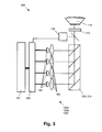
- An example of a display system 200 according to the second embodiment of the present invention is shown in Fig. 3.
- the display system 200 operates according to the same principle, allowing to determine the colour of a basic colour by using, in a single basic colour light channel 102a, 102b, 102c, at least two light sources 104 having a substantially different spectral characteristic.
- the basic colour light channels 102a, 102b, 102c refer to at least partially the same physical channel, but at different basic colour situations, i.e. at different timings in the timing sequence.
- the display system 200 thus is adapted for displaying different colours by time-sequentially displaying a number of basic colours using basic colour light channels 102a, 102b, 102c.
- the number of basic colour light channels 102a, 102b, 102c corresponds to the number of basic colours used for displaying the colour image.
- the basic colours may be primary colours or other colours and the number of colours is not limited to three as described in more detail in the first embodiment.
- the number of light sources 104 may be equal to or larger than the number of basic colour light channels 102a, 102b, 102c.
- the light sources 104 typically are imaged on an aperture, an optical component or a modulator, e.g. using standard optical elements 105, thus providing a specific light path.
- the light sources 104 may be of the same type and may have the same properties as the light sources 104 described in the first embodiment.
- the basic colour light channels 102a, 102b, 102c are used time-sequentially, meaning that the basic colours are generated sequentially and not at the same moment in time.
- the basic colour light channels 102a, 102b, 102c therefore can use components of the device or part of the light path used in other basic colour light channels 102a, 102b, 102c.
- the basic colour light channels 102a, 102b, 102c can e.g. all control/use the same light sources 104, can control/use partly the same light sources 104 as used in other basic colour light channels 102a, 102b, 102c or can control/use different light sources 104 in some or in each basic colour light channel 102a, 102b, 102c.
- the number of basic colour light channels is 3 and the number of light sources is 4, whereby all light sources are controlled for the three basic colour light channels 102a, 102b, 102c.
- At least two light sources 104 may have a substantially different spectral characteristic.
- Light sources having a substantially different spectral characteristic may e.g. be light sources having a substantial difference in peak emission wavelength or a substantial difference in average emission wavelength.
- the substantial difference in peak emission wavelength or a substantial difference in average emission wavelength may e.g. be a difference of at least 10nm, e.g. be a difference of at least 20nm or e.g. a difference in the range 10nm to 100nm.
- the spectral characteristic of the light sources 104 may be a narrow bandwith characteristic, or in other words, the light sources 104 may emit in a narrow spectral wavelength range.
- a narrow bandwidth may be meant substantially emitting in a wavelength range not larger than 200 nm, preferably not larger than 150 nm, more preferably not larger than 100 nm.
- a narrow bandwidth may be determined by the full width at half maximum (FWHM) for the emission peak being less than 50nm.
- light sources having a substantially different spectral characteristic may be selected by selecting different subtypes of light emitting devices, such as light emitting diodes (LEDs).
- the display system 200 also comprises an adjuster 206 for adjusting the relative proportion of a luminous output of the light sources 104 used in a basic colour light channel 102a, 102b, 102c.
- the light sources 104 being part of that basic colour light channel 102a, 102b, 102c may be driven with different intensity levels thus composing the basic colour for that basic colour light channel 102a, 102b, 102c.
- the same or other light sources are driven to generate a second basic colour light beam, possibly followed by driving of the same or other light sources to generate a further basic colour light beam.
- the relative proportion of the luminous output of the different light sources 104 used in a basic colour light channel can be adjusted, as this allows to adjust the colour of a basic colour light beam, e.g. to set the basic colour light beam to a specific colour point.
- the adjuster 206 may adjust the relative proportion of a luminous output of the light sources 104 used in a basic colour light channel by separately controlling the luminous output of these light sources 104.
- the adjuster 206 furthermore may control the relative proportion of a luminous output of the light sources 104 separately within each basic colour light channel 102a, 102b, 102c, i.e. in the different parts in the illumination sequence. Consequently, a time-sequential adjustment of the light sources 104 may be performed, in agreement with the time-sequential basic colour illumination.
- the intensity levels thus in other words may be controlled so that the colour point of each basic colour equals a predetermined colour point for that basic colour.
- the latter may be for example a colour point being constant over time, or constant during the dimming of the light sources 104, e.g. LEDs, or constant when the temperature of the light sources 104, e.g. LEDs is changing.
- a means for storing 107 for storing information related to the adjusting of the average luminous output of the different light sources 104 in the different basic colour light channels 102a, 102b, 102c may be provided.
- the information may be a model for the control signals for adjusting the average luminous output of the different light sources 104 in the different basic colour light channels 102a, 102b, 102c.
- Such a means for storing 107 may be implemented as a stored sequence using conventional logic and memory circuitry for example, although the invention is not limited thereto.
- the means for storing 107 may be incorporated in or may be part of the adjuster 206. Alternatively, the means for storing 107 may be a separate element.
- Fig. 4 shows the separate luminous output levels for the different light sources 104 during different time periods of a cycle of the colour-sequential illumination.
- Signal 402 illustrates the driving level for a red light source in the example display system 200 of Fig. 3
- signal 404 illustrates the driving level for a first green light source in the example display system 200 of Fig.
- signal 406 illustrates the driving intensity for a second green light source
- signal 408 illustrates the driving intensity of the blue light source in the example display system 200 of Fig. 3.
- Time period T 1 thereby corresponds to the time wherein the red basic colour illumination is performed
- time period T 2 corresponds to the time wherein the green basic colour illumination is performed
- time period T 3 corresponds to the time wherein the blue basic colour illumination is performed.
- the display system 200 typically also may comprise at least one light combination system 208 that may be used or partly used in each of the basic colour light channels 102a, 102b, 102c.
- a light combination system 208 may be one or more dichroic filters, interference filters, holographic filters or dichroic prisms such as e.g. an X-cube.
- the light combination system 208 also brings the different basic colour beams on the same light path thus acting as a basic colour combiner 212.
- a single common modulator 210 typically may be used providing sequences of image information for the different basic colours in the image.
- Such a single common modulator 210 may be a light valve, such as a spatial light modulators assembly like e.g. a deformable mirror device (DMD) engine, a liquid crystal display (LCD) engine or a liquid crystal on silicon (LCOS) engine. It can comprise either transmissive or reflective light modulators. Transmissive devices modulate the light beam as it passes through the unit. Reflective devices modulate the light as it reflects from a mirror inside the unit.
- the light sources 104 may be modulated according to established principles known by the person skilled in the art, in order to obtain light beams comprising picture information. The modulated basic colour light beams then are directed towards a projection lens 114.
- one or more optical sensors 116 can be optionally placed in the light path of at least one basic colour light channel 102a, 102b, 102c.
- the colour sensor 116 can be used in the light path to control the actual colour point or the spectral composition of the sequences of light that is used to illuminate the modulator 210.
- the sensor can be placed at the screen or aiming at the screen so that the colors can be checked there, e.g. such that a colour point can be measured there.
- the sensor 116 typically may perform analysis for the different sequences for the different basic colours that are sequentially presented to the modulator 210.
- the optical sensor or optical sensors 116 can for example be spectrally sensitive, so that the light output and colour point can be monitored and fed back to the adjuster 106 of the light sources 104. In this way the light output can be adapted until a predetermined colour point is reached.
- the system thus can be used as an automated and/or automatic feed back loop for correcting for colour shifts over time.
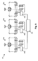
- the present invention relates to a multi-display system comprising at least two displays according to any of embodiments 1 or 2, wherein a basic colour adjustment system is provided in order to allow to set the basic colours in each display equally.
- An example of such a multi-display system 300 is illustrated in Fig.
- the adjusters 306a, 306b, 306c also may be comprised in a single adjuster 360 linking the adjustment signals thus allowing to set basic colours in different displays 302a, 302b, 302c of a multi-display system 300 equal.
- a detector system (not represented in the drawings) may be present allowing to automatically or automated adjustment of a colour of basic colours in the display systems 302a, 302b, 302c. It is an advantage of embodiments of the present invention that adjustment to basic colours as well as adjustment to combinations of basic colours can be performed. Adjustment of e.g. the white point of the display and the intensity can in particular embodiments with basic colours RGB be obtained by balancing the contribution of these three basic colours red, green and blue. Also adjustment of other colours being a combination of some or all basic colours may be performed by adjusting the contribution of the basic colours in the system.
- the present invention also relates to methods for setting/adjusting a colour display.
- the method typically comprises determining a colour point for a basic colour of a combination of basic colours generated in basic colour light channels in the display and adjusting the colour point to a predetermined colour point by adjusting a relative proportion of the illumination of different light sources in at least one of the basic colour light channels.
- the present invention also relates to an adjuster, which also may be referred to as a controller, whereby the adjuster is adapted for performing adjustment of the relative proportion of the luminous output of at least two light sources in a basic colour light channel in order to adjust the colour of the basic colour generated in the basic colour light channel.
- an adjuster/controller may especially be adapted to operate in display systems as described in one of the above embodiments.
- the adjuster/controller therefore may have all features as described for the adjuster/controller in one of the above embodiments.
Landscapes
- Engineering & Computer Science (AREA)
- Multimedia (AREA)
- Signal Processing (AREA)
- Physics & Mathematics (AREA)
- General Physics & Mathematics (AREA)
- Optics & Photonics (AREA)
- Computer Graphics (AREA)
- Computer Hardware Design (AREA)
- Theoretical Computer Science (AREA)
- Projection Apparatus (AREA)
- Polarising Elements (AREA)
- Liquid Crystal (AREA)
- Non-Portable Lighting Devices Or Systems Thereof (AREA)
- Control Of Indicators Other Than Cathode Ray Tubes (AREA)
Applications Claiming Priority (1)
| Application Number | Priority Date | Filing Date | Title |
|---|---|---|---|
| US63143004P | 2004-11-30 | 2004-11-30 |
Publications (1)
| Publication Number | Publication Date |
|---|---|
| EP1662804A1 true EP1662804A1 (en) | 2006-05-31 |
Family
ID=35998425
Family Applications (3)
| Application Number | Title | Priority Date | Filing Date |
|---|---|---|---|
| EP05447265A Ceased EP1672407B1 (en) | 2004-11-30 | 2005-11-29 | Dynamic array polariser and polarisation recovery system incorporating same |
| EP05447264A Ceased EP1662804A1 (en) | 2004-11-30 | 2005-11-29 | Display systems with and methods for multiple source colour illumination |
| EP05447268A Ceased EP1662805A1 (en) | 2004-11-30 | 2005-11-30 | Efficient illumination for display systems and in methods for displaying |
Family Applications Before (1)
| Application Number | Title | Priority Date | Filing Date |
|---|---|---|---|
| EP05447265A Ceased EP1672407B1 (en) | 2004-11-30 | 2005-11-29 | Dynamic array polariser and polarisation recovery system incorporating same |
Family Applications After (1)
| Application Number | Title | Priority Date | Filing Date |
|---|---|---|---|
| EP05447268A Ceased EP1662805A1 (en) | 2004-11-30 | 2005-11-30 | Efficient illumination for display systems and in methods for displaying |
Country Status (5)
| Country | Link |
|---|---|
| US (3) | US7618147B2 (enExample) |
| EP (3) | EP1672407B1 (enExample) |
| JP (3) | JP4741353B2 (enExample) |
| AT (1) | ATE475903T1 (enExample) |
| DE (1) | DE602005022535D1 (enExample) |
Cited By (8)
| Publication number | Priority date | Publication date | Assignee | Title |
|---|---|---|---|---|
| WO2006107546A1 (en) * | 2005-03-30 | 2006-10-12 | 3M Innovative Properties Company | Illumination system and projection system using same |
| EP1947866A1 (en) | 2006-12-27 | 2008-07-23 | Barco NV | Methods and systems for imaging by spectrum sequentially display images |
| US7410261B2 (en) | 2005-05-20 | 2008-08-12 | 3M Innovative Properties Company | Multicolor illuminator system |
| WO2009031103A1 (en) * | 2007-09-07 | 2009-03-12 | Philips Intellectual Property & Standards Gmbh | Multi color light source |
| WO2010079072A1 (de) * | 2009-01-08 | 2010-07-15 | Osram Gesellschaft mit beschränkter Haftung | Projektionsmodul |
| EP2242279A3 (en) * | 2008-09-26 | 2010-12-08 | Casio Computer Co., Ltd. | Projection apparatus and projection method |
| EP2220428A4 (en) * | 2007-05-23 | 2011-06-15 | Cymtec Ltd | LIGHT SOURCE ARRANGEMENTS |
| DE102010002745B4 (de) | 2009-03-12 | 2021-12-30 | Casio Computer Co., Ltd. | Projektionsvorrichtung, Projektionsverfahren und Speichermedium |
Families Citing this family (33)
| Publication number | Priority date | Publication date | Assignee | Title |
|---|---|---|---|---|
| JP2007166271A (ja) * | 2005-12-14 | 2007-06-28 | Seiko Epson Corp | プロジェクションシステムおよびプロジェクタ |
| US20080048956A1 (en) * | 2006-08-22 | 2008-02-28 | Texas Instruments Incorporated | Color management system and method for a visual display apparatus |
| JP4946279B2 (ja) * | 2006-09-04 | 2012-06-06 | 株式会社Jvcケンウッド | 照明装置及び画像表示装置 |
| US7766490B2 (en) * | 2006-12-13 | 2010-08-03 | Philips Lumileds Lighting Company, Llc | Multi-color primary light generation in a projection system using LEDs |
| US20080204382A1 (en) * | 2007-02-23 | 2008-08-28 | Kevin Len Li Lim | Color management controller for constant color point in a field sequential lighting system |
| JP5150183B2 (ja) * | 2007-09-26 | 2013-02-20 | 三洋電機株式会社 | 投写型映像表示装置 |
| US8760507B2 (en) * | 2008-08-05 | 2014-06-24 | Inspectron, Inc. | Light pipe for imaging head of video inspection device |
| JP5344550B2 (ja) * | 2008-08-26 | 2013-11-20 | キヤノン株式会社 | 画像投射装置及び画像表示システム |
| US20100103380A1 (en) * | 2008-10-23 | 2010-04-29 | Texas Instruments Incorporated | Critical abbe illumination configuration |
| DE102008059639A1 (de) * | 2008-11-28 | 2010-06-02 | Osram Gesellschaft mit beschränkter Haftung | Verfahren und Vorrichtung zum Farbpunktabgleich einer Leuchteinheit |
| US8162483B2 (en) * | 2009-06-25 | 2012-04-24 | Eastman Kodak Company | Hierarchical light intensity control in light projector |
| US8142021B2 (en) * | 2009-06-25 | 2012-03-27 | Eastman Kodak Company | Dump path light intensity sensing in light projector |
| US8220938B2 (en) * | 2009-06-25 | 2012-07-17 | Eastman Kodak Company | Image path light intensity sensing during a blanking period between a left-eye light beam and a right-eye light beam in a stereoscopic light projector |
| US8237777B2 (en) * | 2009-06-25 | 2012-08-07 | Eastman Kodak Company | Stereoscopic image intensity balancing in light projector |
| US20100328611A1 (en) * | 2009-06-25 | 2010-12-30 | Silverstein Barry D | Leakage light intensity sensing in light projector |
| CN102667579A (zh) * | 2009-09-15 | 2012-09-12 | 恩迪斯外科影像有限公司 | 用于图像的修正、测量和显示的方法和系统 |
| US8952980B2 (en) | 2010-08-09 | 2015-02-10 | Gsi Group, Inc. | Electronic color and luminance modification |
| JP5808118B2 (ja) * | 2011-03-01 | 2015-11-10 | 三菱電機株式会社 | 投写型表示装置 |
| CN104081546B (zh) * | 2012-01-31 | 2016-12-21 | 夏普株式会社 | Led分类方法、led分类装置 |
| JP6070982B2 (ja) * | 2012-10-04 | 2017-02-01 | 日本精機株式会社 | 表示装置 |
| US10788678B2 (en) | 2013-05-17 | 2020-09-29 | Excelitas Canada, Inc. | High brightness solid state illumination system for fluorescence imaging and analysis |
| JP5880496B2 (ja) * | 2013-07-19 | 2016-03-09 | ウシオ電機株式会社 | 光源装置およびプロジェクタ |
| JP6299460B2 (ja) * | 2013-10-16 | 2018-03-28 | セイコーエプソン株式会社 | プロジェクター |
| US9329461B2 (en) | 2013-10-28 | 2016-05-03 | Dell Products, Lp | Hybrid light engine for projector |
| CN104977722A (zh) * | 2014-04-03 | 2015-10-14 | 光宝科技股份有限公司 | 投影装置 |
| KR102561101B1 (ko) | 2018-02-19 | 2023-07-28 | 삼성전자주식회사 | 확장된 시야창을 제공하는 홀로그래픽 디스플레이 장치 |
| US10901310B2 (en) | 2018-07-24 | 2021-01-26 | Qualcomm Incorporated | Adjustable light distribution for active depth sensing systems |
| ES3011011T3 (en) | 2018-11-19 | 2025-04-07 | Flightsafety Int Inc | Method and apparatus for remapping pixel locations |
| WO2020106892A1 (en) | 2018-11-20 | 2020-05-28 | FlightSafety International | Rear projection simulator with freeform fold mirror |
| US11022813B2 (en) | 2019-04-08 | 2021-06-01 | Qualcomm Incorporated | Multifunction light projector with multistage adjustable diffractive optical elements |
| US11521504B2 (en) * | 2020-03-18 | 2022-12-06 | Rosemount Aerospace Inc. | Method and system for aircraft taxi strike alerting |
| EP3907725A1 (en) * | 2020-05-06 | 2021-11-10 | Admesy B.V. | Method and setup for performing a series of optical measurements with a 2d imaging system |
| JP2025112235A (ja) * | 2024-01-18 | 2025-07-31 | 株式会社小糸製作所 | 画像投影装置 |
Citations (8)
| Publication number | Priority date | Publication date | Assignee | Title |
|---|---|---|---|---|
| WO2001043113A1 (en) * | 1999-12-09 | 2001-06-14 | Koninklijke Philips Electronics N.V. | Display systems incorporating light-emitting diode light source |
| EP1161103A2 (en) * | 2000-05-31 | 2001-12-05 | Fujitsu General Limited | Projection method and projector |
| US20020154277A1 (en) * | 2001-04-02 | 2002-10-24 | Hiroshi Mukawa | Image display device |
| JP2003283964A (ja) * | 2002-03-26 | 2003-10-03 | Olympus Optical Co Ltd | 映像表示装置 |
| US20040036668A1 (en) * | 2002-08-21 | 2004-02-26 | Nec Viewtechnology, Ltd. | Video display device |
| WO2004039085A1 (en) * | 2002-10-21 | 2004-05-06 | Imax Corporation | Equipment, systems and methods for control of color in projection displays |
| CN1540394A (zh) * | 2003-04-21 | 2004-10-27 | ������������ʽ���� | 显示装置、照明装置和投影机 |
| JP2004325643A (ja) * | 2003-04-23 | 2004-11-18 | Seiko Epson Corp | プロジェクタ及び光学装置 |
Family Cites Families (37)
| Publication number | Priority date | Publication date | Assignee | Title |
|---|---|---|---|---|
| US4196460A (en) * | 1978-07-14 | 1980-04-01 | Sybron Corporation | Major surgical light |
| JP3040884B2 (ja) * | 1992-08-17 | 2000-05-15 | 日本電信電話株式会社 | 光路変換素子 |
| US5381250A (en) * | 1992-11-06 | 1995-01-10 | Displaytech, Inc. | Electro-optical switch with 4 port modules with electro-optic polarization rotators |
| JPH07284120A (ja) * | 1994-04-07 | 1995-10-27 | Hitachi Ltd | マルチディスプレイ装置 |
| US6560018B1 (en) * | 1994-10-27 | 2003-05-06 | Massachusetts Institute Of Technology | Illumination system for transmissive light valve displays |
| US5808800A (en) * | 1994-12-22 | 1998-09-15 | Displaytech, Inc. | Optics arrangements including light source arrangements for an active matrix liquid crystal image generator |
| EP0968448B1 (en) * | 1997-02-19 | 2004-10-06 | Digital Projection Limited | Illumination system |
| JPH10269802A (ja) * | 1997-03-24 | 1998-10-09 | Sony Corp | 照明装置および映像表示装置 |
| US6049404A (en) * | 1997-04-02 | 2000-04-11 | Macro-Vision Communications Inc. | N+M digitally programmable optical routing switch |
| JP3591220B2 (ja) * | 1997-05-28 | 2004-11-17 | 富士ゼロックス株式会社 | プロジェクタ装置 |
| KR20000069009A (ko) * | 1997-09-22 | 2000-11-25 | 이데이 노부유끼 | 영상 표시 장치 |
| EP0985952A4 (en) * | 1998-03-26 | 2004-07-14 | Mitsubishi Electric Corp | IMAGE DISPLAY AND LIGHT-EMITTING DEVICE |
| US6227669B1 (en) * | 1998-05-26 | 2001-05-08 | Industrial Technology Research Institute | Illumination device and image projection apparatus comprising the device |
| TW380213B (en) * | 1999-01-21 | 2000-01-21 | Ind Tech Res Inst | Illumination apparatus and image projection apparatus includes the same |
| JP2000231344A (ja) * | 1999-02-10 | 2000-08-22 | Toshiba Corp | 投写型表示装置の照明装置 |
| JP3823659B2 (ja) * | 2000-02-04 | 2006-09-20 | セイコーエプソン株式会社 | プロジェクタ |
| JP4214656B2 (ja) * | 2000-03-29 | 2009-01-28 | セイコーエプソン株式会社 | 投射型表示装置 |
| KR100656906B1 (ko) * | 2000-04-20 | 2006-12-15 | 삼성전자주식회사 | 액정 표시 장치용 패널의 제조 방법, 이를 위한 제조장치, 이를 포함하는 인라인 시스템 및 이를 이용한 액정표시 장치의 제조 방법 |
| JP2002244211A (ja) * | 2001-02-22 | 2002-08-30 | Ricoh Co Ltd | 画像投射装置 |
| JP4792665B2 (ja) * | 2001-06-18 | 2011-10-12 | ソニー株式会社 | 光源制御装置および方法、ならびに投射型表示装置 |
| TW500225U (en) * | 2001-07-27 | 2002-08-21 | Kenmos Technology Co Ltd | Polarized light transfer device with light-guide tube |
| JP2003202523A (ja) * | 2001-11-02 | 2003-07-18 | Nec Viewtechnology Ltd | 偏光ユニット、該偏光ユニットを用いた偏光照明装置及び該偏光照明装置を用いた投写型表示装置 |
| JP4282925B2 (ja) * | 2001-11-20 | 2009-06-24 | パナソニック株式会社 | 投写型表示装置 |
| JP2003295315A (ja) * | 2002-04-03 | 2003-10-15 | Seiko Epson Corp | 投射型表示装置 |
| JP2003330109A (ja) * | 2002-05-09 | 2003-11-19 | Seiko Epson Corp | 照明装置および投射型表示装置 |
| US6736514B2 (en) * | 2002-06-21 | 2004-05-18 | Eastman Kodak Company | Imaging apparatus for increased color gamut using dual spatial light modulators |
| JP4274766B2 (ja) * | 2002-09-12 | 2009-06-10 | オリンパス株式会社 | 照明装置及びその照明装置を使用した画像投影装置 |
| JP2004157522A (ja) * | 2002-10-17 | 2004-06-03 | Sony Corp | 画像生成装置、画像表示装置、画像表示方法、及び光変調素子調整装置 |
| US7929214B2 (en) * | 2002-11-07 | 2011-04-19 | Sony Deutschland Gmbh | Illumination arrangement for a projection system |
| JP2004184852A (ja) * | 2002-12-05 | 2004-07-02 | Olympus Corp | 表示装置、光源装置、及び照明装置 |
| JP2004226738A (ja) * | 2003-01-23 | 2004-08-12 | Seiko Epson Corp | 光学素子及び照明装置並びに投射型表示装置 |
| JP3975948B2 (ja) * | 2003-03-10 | 2007-09-12 | セイコーエプソン株式会社 | 照明装置及び投射装置 |
| JP2004286946A (ja) * | 2003-03-20 | 2004-10-14 | Minolta Co Ltd | プロジェクタおよび照明光学系 |
| JP3891141B2 (ja) * | 2003-04-21 | 2007-03-14 | セイコーエプソン株式会社 | 表示装置 |
| JP2004325630A (ja) * | 2003-04-23 | 2004-11-18 | Seiko Epson Corp | 投射型表示装置 |
| JP3858850B2 (ja) * | 2003-05-06 | 2006-12-20 | セイコーエプソン株式会社 | 表示装置、及び表示方法、並びにプロジェクタ |
| US7445340B2 (en) * | 2005-05-19 | 2008-11-04 | 3M Innovative Properties Company | Polarized, LED-based illumination source |
-
2005
- 2005-11-29 EP EP05447265A patent/EP1672407B1/en not_active Ceased
- 2005-11-29 DE DE602005022535T patent/DE602005022535D1/de not_active Expired - Lifetime
- 2005-11-29 JP JP2005344236A patent/JP4741353B2/ja not_active Expired - Fee Related
- 2005-11-29 JP JP2005344248A patent/JP2006171722A/ja active Pending
- 2005-11-29 EP EP05447264A patent/EP1662804A1/en not_active Ceased
- 2005-11-29 AT AT05447265T patent/ATE475903T1/de not_active IP Right Cessation
- 2005-11-30 US US11/289,282 patent/US7618147B2/en active Active
- 2005-11-30 US US11/289,280 patent/US7495830B2/en active Active
- 2005-11-30 JP JP2005346799A patent/JP2006154834A/ja active Pending
- 2005-11-30 US US11/289,281 patent/US7692866B2/en active Active
- 2005-11-30 EP EP05447268A patent/EP1662805A1/en not_active Ceased
Patent Citations (10)
| Publication number | Priority date | Publication date | Assignee | Title |
|---|---|---|---|---|
| WO2001043113A1 (en) * | 1999-12-09 | 2001-06-14 | Koninklijke Philips Electronics N.V. | Display systems incorporating light-emitting diode light source |
| EP1161103A2 (en) * | 2000-05-31 | 2001-12-05 | Fujitsu General Limited | Projection method and projector |
| US20020154277A1 (en) * | 2001-04-02 | 2002-10-24 | Hiroshi Mukawa | Image display device |
| JP2003283964A (ja) * | 2002-03-26 | 2003-10-03 | Olympus Optical Co Ltd | 映像表示装置 |
| US20040036668A1 (en) * | 2002-08-21 | 2004-02-26 | Nec Viewtechnology, Ltd. | Video display device |
| WO2004039085A1 (en) * | 2002-10-21 | 2004-05-06 | Imax Corporation | Equipment, systems and methods for control of color in projection displays |
| CN1540394A (zh) * | 2003-04-21 | 2004-10-27 | ������������ʽ���� | 显示装置、照明装置和投影机 |
| US20040263500A1 (en) * | 2003-04-21 | 2004-12-30 | Seiko Epson Corporation | Display device, lighting device and projector |
| JP2004325643A (ja) * | 2003-04-23 | 2004-11-18 | Seiko Epson Corp | プロジェクタ及び光学装置 |
| US20040263802A1 (en) * | 2003-04-23 | 2004-12-30 | Seiko Epson Corporation | Projector and optical device |
Non-Patent Citations (1)
| Title |
|---|
| STUPP E. H., BRENNESHOLTZ M.S.: "Projection Displays", 1999, JOHN WILEY & SONS LTD, CHICHESTER, West Sussex, England, ISBN: 0-471-98253-9, pages: 264 - 266 * |
Cited By (12)
| Publication number | Priority date | Publication date | Assignee | Title |
|---|---|---|---|---|
| WO2006107546A1 (en) * | 2005-03-30 | 2006-10-12 | 3M Innovative Properties Company | Illumination system and projection system using same |
| US7422330B2 (en) | 2005-03-30 | 2008-09-09 | 3M Innovative Properties Company | Illumination system and projection system using same |
| US7410261B2 (en) | 2005-05-20 | 2008-08-12 | 3M Innovative Properties Company | Multicolor illuminator system |
| EP1947866A1 (en) | 2006-12-27 | 2008-07-23 | Barco NV | Methods and systems for imaging by spectrum sequentially display images |
| US7812300B2 (en) | 2006-12-27 | 2010-10-12 | Barco N.V. | Methods and systems for imaging having an illumination splitting means with a dynamic selecting means and a static selecting means |
| EP2220428A4 (en) * | 2007-05-23 | 2011-06-15 | Cymtec Ltd | LIGHT SOURCE ARRANGEMENTS |
| WO2009031103A1 (en) * | 2007-09-07 | 2009-03-12 | Philips Intellectual Property & Standards Gmbh | Multi color light source |
| EP2242279A3 (en) * | 2008-09-26 | 2010-12-08 | Casio Computer Co., Ltd. | Projection apparatus and projection method |
| US8408719B2 (en) | 2008-09-26 | 2013-04-02 | Casio Computer Co., Ltd. | Projection apparatus and projection method |
| CN101945291B (zh) * | 2008-09-26 | 2014-01-29 | 卡西欧计算机株式会社 | 投影装置及投影方法 |
| WO2010079072A1 (de) * | 2009-01-08 | 2010-07-15 | Osram Gesellschaft mit beschränkter Haftung | Projektionsmodul |
| DE102010002745B4 (de) | 2009-03-12 | 2021-12-30 | Casio Computer Co., Ltd. | Projektionsvorrichtung, Projektionsverfahren und Speichermedium |
Also Published As
| Publication number | Publication date |
|---|---|
| US7692866B2 (en) | 2010-04-06 |
| US7495830B2 (en) | 2009-02-24 |
| JP2006195432A (ja) | 2006-07-27 |
| JP4741353B2 (ja) | 2011-08-03 |
| US7618147B2 (en) | 2009-11-17 |
| US20060132403A1 (en) | 2006-06-22 |
| EP1672407A1 (en) | 2006-06-21 |
| JP2006154834A (ja) | 2006-06-15 |
| JP2006171722A (ja) | 2006-06-29 |
| EP1672407B1 (en) | 2010-07-28 |
| ATE475903T1 (de) | 2010-08-15 |
| DE602005022535D1 (de) | 2010-09-09 |
| EP1662805A1 (en) | 2006-05-31 |
| US20060132910A1 (en) | 2006-06-22 |
| US20060132772A1 (en) | 2006-06-22 |
Similar Documents
| Publication | Publication Date | Title |
|---|---|---|
| US7692866B2 (en) | Display systems with and methods for multiple source colour illumination | |
| US7283181B2 (en) | Selectable color adjustment for image display | |
| CN108781279B (zh) | 生成具有三原色的图像的方法、光投影系统及其光学组件 | |
| US7391475B2 (en) | Display image generation with differential illumination | |
| US7460179B2 (en) | Adaptive image display | |
| US6631995B2 (en) | Method of and device for generating an image having a desired brightness | |
| US8979272B2 (en) | Multi-primary color display | |
| US9429761B2 (en) | Color synthesis optical element, projection-type display device using same, and method for controlling display thereof | |
| US20040036668A1 (en) | Video display device | |
| JP4524985B2 (ja) | 光量制御装置、照明装置、その制御方法およびプロジェクタ | |
| JP2009058786A (ja) | 画像表示装置 | |
| US20160073072A1 (en) | Projection image display apparatus | |
| US11016375B2 (en) | Control of color primaries and white point in a laser-phosphor projector | |
| CN108227356A (zh) | 一种投影显示系统 | |
| US9635327B2 (en) | Projector, color correction device, and projection method | |
| US10104352B2 (en) | Projector and image display method | |
| JP4552985B2 (ja) | 画像表示装置 | |
| CN110874003B (zh) | 投影光学系统及其偏色调整方法 | |
| JP2006330177A (ja) | 表示装置及びプロジェクタ | |
| JP2014157823A (ja) | プロジェクタおよびプロジェクタの制御方法 | |
| US20180220111A1 (en) | Projector and method of controlling projector | |
| JP2009098627A (ja) | 投写型映像表示装置 | |
| JP2012104489A (ja) | プロジェクタおよびプロジェクタの制御方法 | |
| JP2004286964A (ja) | 色分離方法、色合成方法、及び表示装置 |
Legal Events
| Date | Code | Title | Description |
|---|---|---|---|
| PUAI | Public reference made under article 153(3) epc to a published international application that has entered the european phase |
Free format text: ORIGINAL CODE: 0009012 |
|
| AK | Designated contracting states |
Kind code of ref document: A1 Designated state(s): AT BE BG CH CY CZ DE DK EE ES FI FR GB GR HU IE IS IT LI LT LU LV MC NL PL PT RO SE SI SK TR |
|
| AX | Request for extension of the european patent |
Extension state: AL BA HR MK YU |
|
| 17P | Request for examination filed |
Effective date: 20061027 |
|
| AKX | Designation fees paid |
Designated state(s): AT BE BG CH CY CZ DE DK EE ES FI FR GB GR HU IE IS IT LI LT LU LV MC NL PL PT RO SE SI SK TR |
|
| 17Q | First examination report despatched |
Effective date: 20070622 |
|
| STAA | Information on the status of an ep patent application or granted ep patent |
Free format text: STATUS: THE APPLICATION HAS BEEN REFUSED |
|
| 18R | Application refused |
Effective date: 20101007 |