EP1672407B1 - Dynamic array polariser and polarisation recovery system incorporating same - Google Patents
Dynamic array polariser and polarisation recovery system incorporating same Download PDFInfo
- Publication number
- EP1672407B1 EP1672407B1 EP05447265A EP05447265A EP1672407B1 EP 1672407 B1 EP1672407 B1 EP 1672407B1 EP 05447265 A EP05447265 A EP 05447265A EP 05447265 A EP05447265 A EP 05447265A EP 1672407 B1 EP1672407 B1 EP 1672407B1
- Authority
- EP
- European Patent Office
- Prior art keywords
- polarisation
- light
- beams
- polarised
- unpolarised
- Prior art date
- Legal status (The legal status is an assumption and is not a legal conclusion. Google has not performed a legal analysis and makes no representation as to the accuracy of the status listed.)
- Ceased
Links
Images


Classifications
-
- G—PHYSICS
- G02—OPTICS
- G02B—OPTICAL ELEMENTS, SYSTEMS OR APPARATUS
- G02B27/00—Optical systems or apparatus not provided for by any of the groups G02B1/00 - G02B26/00, G02B30/00
- G02B27/28—Optical systems or apparatus not provided for by any of the groups G02B1/00 - G02B26/00, G02B30/00 for polarising
- G02B27/283—Optical systems or apparatus not provided for by any of the groups G02B1/00 - G02B26/00, G02B30/00 for polarising used for beam splitting or combining
- G02B27/285—Optical systems or apparatus not provided for by any of the groups G02B1/00 - G02B26/00, G02B30/00 for polarising used for beam splitting or combining comprising arrays of elements, e.g. microprisms
-
- G—PHYSICS
- G02—OPTICS
- G02B—OPTICAL ELEMENTS, SYSTEMS OR APPARATUS
- G02B27/00—Optical systems or apparatus not provided for by any of the groups G02B1/00 - G02B26/00, G02B30/00
- G02B27/28—Optical systems or apparatus not provided for by any of the groups G02B1/00 - G02B26/00, G02B30/00 for polarising
- G02B27/283—Optical systems or apparatus not provided for by any of the groups G02B1/00 - G02B26/00, G02B30/00 for polarising used for beam splitting or combining
-
- G—PHYSICS
- G03—PHOTOGRAPHY; CINEMATOGRAPHY; ANALOGOUS TECHNIQUES USING WAVES OTHER THAN OPTICAL WAVES; ELECTROGRAPHY; HOLOGRAPHY
- G03B—APPARATUS OR ARRANGEMENTS FOR TAKING PHOTOGRAPHS OR FOR PROJECTING OR VIEWING THEM; APPARATUS OR ARRANGEMENTS EMPLOYING ANALOGOUS TECHNIQUES USING WAVES OTHER THAN OPTICAL WAVES; ACCESSORIES THEREFOR
- G03B21/00—Projectors or projection-type viewers; Accessories therefor
- G03B21/14—Details
- G03B21/20—Lamp housings
- G03B21/206—Control of light source other than position or intensity
-
- G—PHYSICS
- G09—EDUCATION; CRYPTOGRAPHY; DISPLAY; ADVERTISING; SEALS
- G09G—ARRANGEMENTS OR CIRCUITS FOR CONTROL OF INDICATING DEVICES USING STATIC MEANS TO PRESENT VARIABLE INFORMATION
- G09G3/00—Control arrangements or circuits, of interest only in connection with visual indicators other than cathode-ray tubes
- G09G3/20—Control arrangements or circuits, of interest only in connection with visual indicators other than cathode-ray tubes for presentation of an assembly of a number of characters, e.g. a page, by composing the assembly by combination of individual elements arranged in a matrix no fixed position being assigned to or needed to be assigned to the individual characters or partial characters
- G09G3/34—Control arrangements or circuits, of interest only in connection with visual indicators other than cathode-ray tubes for presentation of an assembly of a number of characters, e.g. a page, by composing the assembly by combination of individual elements arranged in a matrix no fixed position being assigned to or needed to be assigned to the individual characters or partial characters by control of light from an independent source
- G09G3/3406—Control of illumination source
-
- H—ELECTRICITY
- H04—ELECTRIC COMMUNICATION TECHNIQUE
- H04N—PICTORIAL COMMUNICATION, e.g. TELEVISION
- H04N5/00—Details of television systems
- H04N5/74—Projection arrangements for image reproduction, e.g. using eidophor
-
- H—ELECTRICITY
- H04—ELECTRIC COMMUNICATION TECHNIQUE
- H04N—PICTORIAL COMMUNICATION, e.g. TELEVISION
- H04N7/00—Television systems
- H04N7/01—Conversion of standards, e.g. involving analogue television standards or digital television standards processed at pixel level
- H04N7/0127—Conversion of standards, e.g. involving analogue television standards or digital television standards processed at pixel level by changing the field or frame frequency of the incoming video signal, e.g. frame rate converter
- H04N7/013—Conversion of standards, e.g. involving analogue television standards or digital television standards processed at pixel level by changing the field or frame frequency of the incoming video signal, e.g. frame rate converter the incoming video signal comprising different parts having originally different frame rate, e.g. video and graphics
-
- H—ELECTRICITY
- H04—ELECTRIC COMMUNICATION TECHNIQUE
- H04N—PICTORIAL COMMUNICATION, e.g. TELEVISION
- H04N7/00—Television systems
- H04N7/01—Conversion of standards, e.g. involving analogue television standards or digital television standards processed at pixel level
- H04N7/0127—Conversion of standards, e.g. involving analogue television standards or digital television standards processed at pixel level by changing the field or frame frequency of the incoming video signal, e.g. frame rate converter
- H04N7/0132—Conversion of standards, e.g. involving analogue television standards or digital television standards processed at pixel level by changing the field or frame frequency of the incoming video signal, e.g. frame rate converter the field or frame frequency of the incoming video signal being multiplied by a positive integer, e.g. for flicker reduction
-
- H—ELECTRICITY
- H04—ELECTRIC COMMUNICATION TECHNIQUE
- H04N—PICTORIAL COMMUNICATION, e.g. TELEVISION
- H04N7/00—Television systems
- H04N7/01—Conversion of standards, e.g. involving analogue television standards or digital television standards processed at pixel level
- H04N7/0135—Conversion of standards, e.g. involving analogue television standards or digital television standards processed at pixel level involving interpolation processes
- H04N7/014—Conversion of standards, e.g. involving analogue television standards or digital television standards processed at pixel level involving interpolation processes involving the use of motion vectors
-
- H—ELECTRICITY
- H04—ELECTRIC COMMUNICATION TECHNIQUE
- H04N—PICTORIAL COMMUNICATION, e.g. TELEVISION
- H04N9/00—Details of colour television systems
- H04N9/12—Picture reproducers
- H04N9/31—Projection devices for colour picture display, e.g. using electronic spatial light modulators [ESLM]
- H04N9/3102—Projection devices for colour picture display, e.g. using electronic spatial light modulators [ESLM] using two-dimensional electronic spatial light modulators
- H04N9/3105—Projection devices for colour picture display, e.g. using electronic spatial light modulators [ESLM] using two-dimensional electronic spatial light modulators for displaying all colours simultaneously, e.g. by using two or more electronic spatial light modulators
-
- H—ELECTRICITY
- H04—ELECTRIC COMMUNICATION TECHNIQUE
- H04N—PICTORIAL COMMUNICATION, e.g. TELEVISION
- H04N9/00—Details of colour television systems
- H04N9/12—Picture reproducers
- H04N9/31—Projection devices for colour picture display, e.g. using electronic spatial light modulators [ESLM]
- H04N9/3102—Projection devices for colour picture display, e.g. using electronic spatial light modulators [ESLM] using two-dimensional electronic spatial light modulators
- H04N9/3111—Projection devices for colour picture display, e.g. using electronic spatial light modulators [ESLM] using two-dimensional electronic spatial light modulators for displaying the colours sequentially, e.g. by using sequentially activated light sources
- H04N9/3114—Projection devices for colour picture display, e.g. using electronic spatial light modulators [ESLM] using two-dimensional electronic spatial light modulators for displaying the colours sequentially, e.g. by using sequentially activated light sources by using a sequential colour filter producing one colour at a time
-
- H—ELECTRICITY
- H04—ELECTRIC COMMUNICATION TECHNIQUE
- H04N—PICTORIAL COMMUNICATION, e.g. TELEVISION
- H04N9/00—Details of colour television systems
- H04N9/12—Picture reproducers
- H04N9/31—Projection devices for colour picture display, e.g. using electronic spatial light modulators [ESLM]
- H04N9/3141—Constructional details thereof
- H04N9/3147—Multi-projection systems
-
- H—ELECTRICITY
- H04—ELECTRIC COMMUNICATION TECHNIQUE
- H04N—PICTORIAL COMMUNICATION, e.g. TELEVISION
- H04N9/00—Details of colour television systems
- H04N9/12—Picture reproducers
- H04N9/31—Projection devices for colour picture display, e.g. using electronic spatial light modulators [ESLM]
- H04N9/3141—Constructional details thereof
- H04N9/315—Modulator illumination systems
- H04N9/3158—Modulator illumination systems for controlling the spectrum
-
- H—ELECTRICITY
- H04—ELECTRIC COMMUNICATION TECHNIQUE
- H04N—PICTORIAL COMMUNICATION, e.g. TELEVISION
- H04N9/00—Details of colour television systems
- H04N9/12—Picture reproducers
- H04N9/31—Projection devices for colour picture display, e.g. using electronic spatial light modulators [ESLM]
- H04N9/3141—Constructional details thereof
- H04N9/315—Modulator illumination systems
- H04N9/3167—Modulator illumination systems for polarizing the light beam
-
- G—PHYSICS
- G09—EDUCATION; CRYPTOGRAPHY; DISPLAY; ADVERTISING; SEALS
- G09G—ARRANGEMENTS OR CIRCUITS FOR CONTROL OF INDICATING DEVICES USING STATIC MEANS TO PRESENT VARIABLE INFORMATION
- G09G2320/00—Control of display operating conditions
- G09G2320/02—Improving the quality of display appearance
- G09G2320/0242—Compensation of deficiencies in the appearance of colours
-
- G—PHYSICS
- G09—EDUCATION; CRYPTOGRAPHY; DISPLAY; ADVERTISING; SEALS
- G09G—ARRANGEMENTS OR CIRCUITS FOR CONTROL OF INDICATING DEVICES USING STATIC MEANS TO PRESENT VARIABLE INFORMATION
- G09G2320/00—Control of display operating conditions
- G09G2320/06—Adjustment of display parameters
- G09G2320/0613—The adjustment depending on the type of the information to be displayed
- G09G2320/062—Adjustment of illumination source parameters
-
- G—PHYSICS
- G09—EDUCATION; CRYPTOGRAPHY; DISPLAY; ADVERTISING; SEALS
- G09G—ARRANGEMENTS OR CIRCUITS FOR CONTROL OF INDICATING DEVICES USING STATIC MEANS TO PRESENT VARIABLE INFORMATION
- G09G2360/00—Aspects of the architecture of display systems
- G09G2360/14—Detecting light within display terminals, e.g. using a single or a plurality of photosensors
- G09G2360/145—Detecting light within display terminals, e.g. using a single or a plurality of photosensors the light originating from the display screen
-
- G—PHYSICS
- G09—EDUCATION; CRYPTOGRAPHY; DISPLAY; ADVERTISING; SEALS
- G09G—ARRANGEMENTS OR CIRCUITS FOR CONTROL OF INDICATING DEVICES USING STATIC MEANS TO PRESENT VARIABLE INFORMATION
- G09G3/00—Control arrangements or circuits, of interest only in connection with visual indicators other than cathode-ray tubes
- G09G3/001—Control arrangements or circuits, of interest only in connection with visual indicators other than cathode-ray tubes using specific devices not provided for in groups G09G3/02 - G09G3/36, e.g. using an intermediate record carrier such as a film slide; Projection systems; Display of non-alphanumerical information, solely or in combination with alphanumerical information, e.g. digital display on projected diapositive as background
-
- H—ELECTRICITY
- H04—ELECTRIC COMMUNICATION TECHNIQUE
- H04N—PICTORIAL COMMUNICATION, e.g. TELEVISION
- H04N5/00—Details of television systems
- H04N5/74—Projection arrangements for image reproduction, e.g. using eidophor
- H04N5/7416—Projection arrangements for image reproduction, e.g. using eidophor involving the use of a spatial light modulator, e.g. a light valve, controlled by a video signal
Definitions
- the present invention relates to the field of polarisers and illumination systems. More particularly, the present invention relates to a polariser and an illumination system, e.g. for use in a projection system, having a polarisation recuperation system and methods for illuminating with polarised light.
- a liquid crystal device (LCD) or liquid crystal on semiconductor (LCOS) device may be used in various applications, such as for example displays like in laptop computers, watches and calculators, and such as for example projection systems for projecting information or images onto a distant screen.
- An LCD or LCOS projector basically comprises a light generator such as a lamp for generating illumination light, illumination optics for capturing that light and transferring it to one or a plurality of LCD or LCOS devices comprising light valves, and a projection lens which images the illuminated LCD or LCOS device(s) on a screen.
- a basic property of both LCD and LCOS devices is that they work with polarised light, more particularly with linearly polarised light.
- Polarised light is used together with the properties of the liquid crystal elements to selectively on the one hand transmit and on the other hand reflect or absorb light to produce a modulated light beam, i.e. to produce a pattern of bright and dark pixels, thus creating a desired image. Because almost all illumination sources used in projectors generate non-polarised light, which is light comprising at least two polarisation directions, this light has to be polarised in an optical system either before it reaches the LCD or LCOS device(s) or in the device itself. This may be done by only selecting that part of the light which has a desired polarisation direction, e.g. using a polarising filter, which method, however, leads to a loss of light output for the projector.
- a polarising filter which method, however, leads to a loss of light output for the projector.
- a typical polarisation recuperation device comprises a polarising beam splitter or polarising beam splitter array and a number of polarisation conversion components, as shown for the device 100 in Fig. 1 .
- the light, generated by light sources 102, is directed to a polarisation recuperation device 104 using optical elements 106, 108.
- the light impinges on a number of entrance surfaces 110 of the polarising beam splitter array.
- this light is split-up into two different light paths.
- the two light paths are generally constructed in such a way that at the output surface 114, 116 of the PBS 112 they are put adjacent to each other.
- the output surface 114, 116 of the polarising beam splitters 112 consists out of first types of sub-surfaces 114 and second types of sub-surfaces 116, each emitting light with different polarisation state.
- One or more polarisation conversion components 118 i.e.
- polarisation conversion components 118 substantially change the polarisation state of the light coming out of these second type of output sub-surfaces 116 into the polarisation state of the light coming out of the first type of output sub-surfaces 114 that do not have a polarisation conversion component 118.
- the number of the output sub-surfaces 114, 116 is doubled with respect to the number of entrance surfaces 108.
- the total surface area of the output sub-surfaces 114, 116 is doubled with respect to the total surface area of the input surfaces 108.
- the light output of the illumination system can be high. It is also an advantage of embodiments of the present invention that more compact illumination systems can be obtained or that illumination systems with a larger luminous output can be obtained, compared to prior art devices.
- a particular aspect of the invention provides a polarizer comprising first and second polarizing beam splitters for splitting first and second unpolarized beams each into first and second polarized beams having a different polarization state.
- a controller switches on alternately the first and second unpolarized beams.
- the polarizer further comprises a polarization conversion element after each polarizing beam splitter, arranged such that the second polarized beam from the first unpolarized beam time-shares a same path through the polarization conversion element as the first polarized beam from the second unpolarized beam.
- the controller further switches also the polarization conversion element synchronously with the switching of the unpolarized beams to alternately convert the polarization state or not convert the polarization state of the impinging polarized beam.
- the number of exit surfaces of the polariser can be reduced, e.g. substantially halved, compared to prior art systems, or wherein substantially twice the number of beams can be used compared to prior art systems.
- the light output can be increased.
- substantially halved what is meant is that, for entrance surfaces and exit surfaces of substantially the same size, the number of exit surfaces of the polariser may be equal to the number of entrance surfaces augmented by 1.
- the polarisation conversion element can be controlled to follow the switching of the beams, or vice versa, wherein the switching of the beams can be controlled to follow the switching of the polarisation conversion elements.
- the polariser may have an array, such as e.g. a line, of polarising beam splitters and conversion elements, each conversion element being arranged to receive beams from two or more neighbouring ones of the polarising beam splitters.
- Each polarising beam splitter may be arranged in the path of an array, such as e.g. a line, of unpolarised beams switched on simultaneously.
- the unpolarised beams may be simultaneously switched in a pulsed regime. This can enable the polariser to handle a two-dimensional array of unpolarised beams.
- Another aspect provides a system for lighting, e.g. an illumination system, the system for lighting comprising multiple light sources each generating an unpolarised beam, and a polariser as set out above.
- a system for lighting e.g. an illumination system, the system for lighting comprising multiple light sources each generating an unpolarised beam, and a polariser as set out above.
- the system for lighting e.g. illumination system, or the display adapted for using such a system for lighting illumination system
- a light source controller also referred to as light source modulator
- the sharing may be time-sharing.
- Other ways of switching the beams can be envisaged, such as using optical switches, but these may be less practical and lose some of the advantages.
- the light sources may be light emitting diodes (LEDs) or lasers. These are examples of sources which can have their peak light output increased if they are operated in a modulated mode.
- LEDs light emitting diodes
- lasers lasers
- Another aspect that does not form part of the present invention provides a method of controlling the above described system for lighting, e.g. illumination system or the display comprising such a system for lighting, e.g. illumination system, by modulating the light sources and the polarisation conversion elements synchronously.
- An embodiment not forming part of the invention therefore also relates to a controller for controlling the above illumination system or the display comprising such an illumination system by modulating the light sources and the polarisation conversion elements synchronously.
- Another aspect provides a method for creating a polarised light beam, the method comprising
- Fig. 1 shows a schematic representation of an example of a polarisation recuperation system according to the prior art, used in combination with LED devices.
- Fig. 2 shows an exemplary schematic representation of a polariser and a corresponding system for lighting according to aspects of the present invention.
- Fig. 3 shows a schematic representation of a system for lighting according to a second aspect of the present invention.
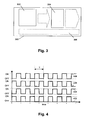
- Fig. 4 shows an exemplary schematic representation of driving signals for driving light sources and polarisation conversion elements generated by a controller with driving circuitry according to embodiments that do not form part of the present invention.
- the present invention relates to a polariser for creating an illumination beam of light having a predetermined polarisation state.
- Illumination beams of light having a predetermined polarisation state typically can be used e.g. for illumination in a projection system or in a backlight based on liquid crystal devices (LCD) or liquid crystal on silicon (LCOS) devices, although the use is not limited thereto.
- the polariser of the present embodiment typically allows having a high luminous output.
- An example of such a polariser 200 is schematically shown by way of illustration in Fig. 2 .
- the polariser 200 typically comprises a plurality of polarising beam splitters 212a, 212b, which may be arranged in an array.
- Such polarising beam splitters 212a, 212b may be made of any solid material such as solid glass, quartz, etc. or may be reflective polarisers, such as for example but not limited to wiregrid polarisers. Such polarising beam splitters 212a, 212b also may be polarisation selective layers included between solid material prisms. Depending on the type of polarisation beam splitter used, the surrounding of the polarisation selective element may be air, e.g. for wiregrid polarisers, or a glass or quartz prism, e.g. for the solid material polarising beam splitters. In Fig. 2 the example of a wiregrid polariser is shown.
- the polarising beam splitters 212a, 212b typically are arranged such that they are adapted to be illuminated on an input surface 210 by a number of images from light sources 202a, 202b, such as for example light emitting diodes (LED), or lasers.
- light sources 202a, 202b typically may be light sources 202a, 202b that can be operated in a pulsed regime, also referred to as a pulsed mode, i.e. wherein the light emission is not continuous but occurs in light pulses.
- light sources 202a, 202b may have the property that, when driven in a pulsed mode, they can have a total light flux integrated over time which can be very similar, i.e.
- light sources 202a, 202b are LEDs.
- all the polarising beam splitters 212a, 212b may be illuminated, each of them by one or more light sources 202a, 202b, such as e.g. LED devices. This is contrary to the prior art arrangement 104 shown in Fig. 1 where empty spaces or even complete empty strips in between the input surfaces have to be foreseen.
- the light sources 202a, 202b may be, but typically are not, part of the polariser 200 according to the first embodiment of the present invention.
- the polarising beam splitters 212a, 212b each split incoming light into a first light path A and a second light path B. Which light path a specific part of the light will follow depends on the polarisation state of the light.
- the polarising beam splitters 212a, 212b are adapted for guiding light having a first polarisation state along a first light path A and for guiding light having a second polarisation state along a second light path B.
- the polarisation states of the light selectively guided by the polarising beam splitter 212a, 212b typically may be two independent polarisation states such as for example but not limited to two orthogonal linear polarisations or a left and right circular polarisation.
- the polarising beam splitters 212a, 212b of the present embodiment are arranged in such a way that the second light path B from a first polarising beam splitter 212a, 212b in the array will be recombined with the first light path A of a neighbouring polarising beam splitter 212b, 212a in the array, so that they will substantially exit the array of polarising beam splitters at the same area of the exit surface 214.
- controllable polarisation conversion elements 218a, 218b are positioned at the exit surface 214 of the polarising beam splitters 212a, 212b.
- the controllable polarisation conversion elements 218a, 218b which may be electrically controlled polarisation conversion strips, are divided into two sub-sets, which are driven to have a different control regarding the polarisation conversion.
- This control e.g. electrical control, will put the polarisation conversion elements 218a, 218b either OFF or ON.
- Such a controllable polarisation conversion element 218a, 218b may be for example a switchable retarder, although other types of controllable polarisation conversion elements 218a, 218b can also be used.
- a switchable retarder can for example be realised by a liquid crystal device, i.e. a ferro-electric liquid crystal cell.
- the controllable polarisation conversion elements 218a, 218b are driven in such a way that neighbouring controllable polarisation conversion elements 218a, 218b corresponding with neighbouring polarising beam splitters 212a, 212b have an inverted function, meaning that they are driven with a 180 degrees phase difference.
- a polarisation conversion element 218a, 218b has to be able (for example, typically it will not be able) to completely convert the polarisation for all wavelengths and all angles of the incident light involved.
- the polarisation conversion elements may be selected such that they provide a conversion of e.g. at least 85%, or at least 90% or at least 95%.
- the material type, the switching time, the switching frequency and the incident light angles may be selected in order to optimise the polarisation conversion.
- part of the light path need not be time-shared, i.e. the light path is either used or not but no different beams are using the same light path. Therefore, no controllable polarisation conversion elements that can be switched are required. Either a static polarisation converter or no conversion element, depending on the selected polarisation state, may be used.
- the light path is only used by a single light source. Therefore, it is an open decision to the user whether this light is used. Using the light increases the amount of light but increases the geometrical extent of the polariser. This decision may be taken based on whether the system can efficiently use the extra light or not.
- a reflecting element may be used as only light on the second light path B is reflected and no light following the first light path is present.
- a reflecting element may be based on a reflective coating or may be based on internal reflection like total internal reflection.
- the light sources 202a, 202b may be divided into two subsets.
- the first subset of light sources 202a e.g. LEDs, generates first unpolarised beams cast on the input surfaces, or in other words input surface area 210.
- the first unpolarised beams will be received by a first subset of polarising beam splitters 212a that split up the first unpolarised beams into first polarised beams following light path A and second polarised beams following light path B.
- light directed on light path A goes to the first subset of controllable polarisation conversion elements 218a.
- the second subset of light sources 202b e.g. LEDs, generates second unpolarised beams cast on the input surfaces, or in other words input surface area 210.
- the second unpolarised beams will be received by a second subset of polarising beam splitters 212b that split up the second unpolarised beams into first polarised beams following light path A and second polarised beams following light path B.
- light directed on light path A goes through the second subset of controllable polarisation conversion elements 218b that run in the opposite or inverted driving mode compared to the first subset of controllable polarisation conversion elements 218a.
- the polarising beam splitters 212a, 212b can be divided into two subsets, depending on the light sources 202a, 202b from which the unpolarised light beams are received, the operation of the polarising beam splitters 212a, 212b as such is not altered, in contrast to the controllable polarisation conversion elements and the light sources.
- the driving sequences of the light sources 202a, 202b, e.g. LEDs, and the controllable polarisation conversion elements 218a, 218b are controlled by signals that synchronize the selection of ON/OFF mode of all the controllable polarisation conversion elements 218a, 218b and the selection of the ON or OFF state of the different light sources 202a, 202b.
- the controllable polarisation conversion elements 218a, 218b and the light sources 202a, 202b are controlled in such a way that during a first fraction of a selected time period, e.g. a first half of a selected time period, a first subset of light sources 202a are illuminating, i.e.
- controllable polarisation conversion elements 218a / 218b are in the ON state, and only the first subset of controllable polarisation conversion elements 218a / 218b are set to the ON mode, whereas the other subset of controllable polarisation conversion elements 218b / 218a are put in the OFF mode.
- Which of the subsets of controllable conversion elements 218b / 218a are put in the ON mode may be selected based on the type of polarisation state of the light that one finally wants to obtain.
- the light sources 202b that were previously OFF are turned ON and the other light sources 202a are turned back OFF again.
- the operational mode of the controllable polarisation conversion components is also inverted. In other words, the unpolarised light beams of the light sources 202a and the unpolarised light beams of the light sources 202b are alternately switched ON/OFF.
- FIG. 2 an array of light sources 202a, 202b divided in two subsets is shown whereby the light sources 202a, 202b are imaged on the input surface 210 using optical elements 206, 208.
- the array of light sources 202a, 202b may be, but typically is not, part of the polariser according to the embodiment of the present invention.
- light sources 202a of the first subset and light sources 202b of the second subset will be alternately pulsed. In other words, the unpolarised light beams from the light sources 202a and from the light sources 202b will be alternately switched ON.
- the polarising beam splitters 212a, 212b all operate in the same way, i.e. they transmit light having a first polarisation state along a first light path A and reflect light having a second polarisation state along a second light path B.
- the light sources 202a, 202b and the polarising beam splitters 212a, 212b are positioned such that light of a first light source 202a directed to a light path B time-shares at least part of the path with light of a neighbouring light source 202b directed on a light path A.
- the light sources 202a and the light sources 202b thus are positioned alternately in the array of light sources 202a, 202b.
- Light path A thus typically may be characterised at each moment as the light path for the light that is transmitted by the polarising beam splitter 212a, 212b whereas light path B may be characterised at each moment as the light path for the light that is reflected by the polarising beam splitter 212a, 212b.
- the second light path B for light from light sources of the first subset of light sources 202a thus are controlled so as to not change the polarisation state.
- Light guided to the first light path A is altered in terms of its polarisation state switching from the first polarisation state to the second polarisation state.
- the latter is performed using the controllable polarisation conversion elements 218a, being in the light path A, i.e. in the light path A for light from the light sources of the first subset 202a of light sources. In this way, all light leaving the polariser 200 has the same polarisation state.
- the light sources 202a are turned OFF and the light sources 202b are turned ON.
- Light having the first polarisation state is transmitted by the polarising beam splitter 212b and guided on the first light path A, while light having a second polarisation state is reflected and guided on a second light path B.
- Light in the second light path B is reflected by a neighbouring polarising beam splitter 212a and the light is further guided outside the polariser 200 without changing the polarisation state. Consequently, controllable polarisation conversion elements 218a which now are present in the second light path B, i.e. the second light path B for light from light sources 202b, are controlled not to change the polarisation state.
- controllable polarisation conversion elements 218a are not active.
- light from light sources 202b on the first light path A is altered in polarisation state to light having the second polarisation state.
- the latter is done by using the controllable polarisation conversion elements 218b, which now are in the first light path A, i.e. the first light path A for light from light sources 202b.
- These controllable polarisation conversion elements 218b were not active during the first fraction of the time period but are active in the second fraction of the time period. In this way, substantially all light exiting the polariser 200 has the same polarisation state and this polarisation state is the same during the full time period of driving the light sources 202a, 202b.
- the present invention relates to a lighting system for lighting such as a backlight or a general lighting device, wherein a beam of polarised light is generated.
- the lighting system is based on the polariser according to the first embodiment, but in the present embodiment an illumination part is part of the system.
- Such an illumination part typically comprises the light sources 202a, 202b as shown in Fig. 2 and optionally optical components such as 206 and 208 for imaging the light sources 202a, 202b on the entrance surface of the polariser 200.
- the light sources 202a, 202b typically are placed in an array and adapted for operating the polariser 200 as described in the first aspect.
- the lighting system also may comprise a controller for controlling the pulsed driving of the light sources 202a, 202b.
- the same controller or a separate controller also may be present for controlling the controllable polarisation conversion elements 218a, 218b of the polariser. If separate controllers are used, typically communication between the controller for the light sources 202a, 202b and the controller for the controllable polarisation conversion elements 218a, 218b may be present to synchronise the driving signals in order to allow operation as described for the first embodiment.
- Driving circuitry for providing driving signals may be part of such a controller or may be separately provided in the system for lighting.
- Fig. 3 schematically illustrates the illumination part 302, the polariser 304 and the optional driver 306 of the lighting system 300.
- the system 300 furthermore may be part of a larger system such as a display or a projection system, further comprising typical components as well known by a person skilled in the art.
- the system 300 may act as a backlight in a display or as an illumination system in a projection system.
- a third aspect, not forming part of the invention relates to a controller for controlling the driving of the light sources 202a, 202b and for the driving of controllable polarisation conversion elements 218a, 218b as shown in Fig. 2 .
- the controller is adapted for driving the light sources 202a, 202b and the controllable polarisation conversion elements 218a, 218b as described in the first embodiment of the present invention.
- An exemplary schematic driving scheme imposed by the controller for driving the different components is shown in Fig. 4 , illustrating the different driving signals for the components as a function of time for different time periods T.
- Signal 402 shows the driving signal for light sources 202a of the first subset
- signal 404 shows the driving signal for light sources 202b of the second subset
- signal 406 shows the driving signal for controllable polarisation conversion elements 218a of a first subset
- signal 408 shows the driving signal of the controllable conversion elements 218b of a second subset.
- the controller may be implemented hardware-based or may be implemented software-based, e.g. implemented on a computing device. It may comprise the driving circuitry or it may co-operate with driving circuitry by controlling the driving circuitry to obtain appropriate driving of the light sources 202a, 202b and/or the controllable polarisation conversion elements 218a, 218b.
- the present invention relates to a method for creating a polarised light beam.
- the method preferably is used with a polariser or a system for lighting as described in any of the above embodiments.
- the method of the present invention typically comprises receiving first and second unpolarised beams and splitting the first and second unpolarised beams each into at least first polarised beams having a first polarisation state and second polarised beams having a second polarisation state differing from the first polarisation state.
- the latter can for example be done using an array of polarising beam splitters 212a, 212b.
- the first and second unpolarised beams typically may be alternately received.
- the method therefore comprises, prior to receiving, creating first and second unpolarised beams, e.g. in an array of light sources 202a, 202b, in an alternating way. Creation of first and second unpolarised beams in an alternating way e.g.
- light sources 202a, 202b which can be driven in pulsed regime may comprise, during a first fraction of a time period, generating light in a first subset of light sources 202a and not in a second subset of light sources 202b and during a second fraction of a time period, different from the first fraction, generating light in a second subset of light sources 202b and not in a first subset of light sources 202a.
- light sources 202a of a first subset and light sources 202b of a second subset may alternately be pulsed.
- the fractions of time periods each may correspond with half a period.
- the light sources 202a, 202b thereby may be typically arranged such that light of the first subset of light sources 202a may be guided on a first subset of polarising beam splitters 212a and light of a second subset of light sources 202b may be guided on a second set of polarising beam splitters 212b, the light sources 202a, 202b and polarising beam splitters 212a, 212b arranged alternately such that a polarising beam splitter 212a of the first subset is neighbouring a polarising beam splitter 212b of the second subset.
- the method furthermore comprises guiding said first polarised beams on first light paths and second polarised beams on second light paths.
- the first light paths and the second light paths typically comprise controllable conversion elements 218a, 218b.
- the second polarised beams of the first unpolarised beams furthermore time-share light paths through said controllable conversion elements with first polarised beams of the second unpolarised beams.
- the method also comprises switching polarisation conversion elements 218a, 218b to alternately convert the polarisation state or not convert the polarisation state of the impinging light in accordance with which of the first unpolarised beams or second unpolarised beams are received.
- the switching of polarisation conversion elements 218a, 218b may be switching ON a first subset of polarisation conversion elements 218a and switching OFF a second subset of polarisation conversion elements 218b during a first fraction of a time period, and inverting the operation during a second fraction of a time period.
- Switching said polarisation conversion elements may comprise controllably switching the polarisation conversion elements 218a, 218b in the ON/OFF state, whereby no polarisation conversion is performed in the OFF state and a polarisation conversion from the first to the second polarisation state and/or from the second to the first polarisation state is performed in the ON state.
- Switching the polarisation conversion elements 218a, 218b typically allows obtaining a light beam having substantially completely a predetermined polarisation state, both spatially and temporally.
- a light beam with a substantially homogeneous average light intensity distribution may be obtained.
- the latter may be caused by the fact that different spatial parts of the output undergo similar filtering, altering or more general manipulating actions.
- pulsed light sources can be used whereby the total flux of light generated over the active and non-active period of the light source exceeds half, preferably 60%, more preferably 70%, even more preferably 80%, still more preferably 90% of the total flux over the same time period in case of a continuous driving method.
Landscapes
- Engineering & Computer Science (AREA)
- Multimedia (AREA)
- Signal Processing (AREA)
- Physics & Mathematics (AREA)
- General Physics & Mathematics (AREA)
- Optics & Photonics (AREA)
- Computer Graphics (AREA)
- Computer Hardware Design (AREA)
- Theoretical Computer Science (AREA)
- Projection Apparatus (AREA)
- Polarising Elements (AREA)
- Liquid Crystal (AREA)
- Non-Portable Lighting Devices Or Systems Thereof (AREA)
- Control Of Indicators Other Than Cathode Ray Tubes (AREA)
Applications Claiming Priority (1)
| Application Number | Priority Date | Filing Date | Title |
|---|---|---|---|
| US63143004P | 2004-11-30 | 2004-11-30 |
Publications (2)
| Publication Number | Publication Date |
|---|---|
| EP1672407A1 EP1672407A1 (en) | 2006-06-21 |
| EP1672407B1 true EP1672407B1 (en) | 2010-07-28 |
Family
ID=35998425
Family Applications (3)
| Application Number | Title | Priority Date | Filing Date |
|---|---|---|---|
| EP05447265A Ceased EP1672407B1 (en) | 2004-11-30 | 2005-11-29 | Dynamic array polariser and polarisation recovery system incorporating same |
| EP05447264A Ceased EP1662804A1 (en) | 2004-11-30 | 2005-11-29 | Display systems with and methods for multiple source colour illumination |
| EP05447268A Ceased EP1662805A1 (en) | 2004-11-30 | 2005-11-30 | Efficient illumination for display systems and in methods for displaying |
Family Applications After (2)
| Application Number | Title | Priority Date | Filing Date |
|---|---|---|---|
| EP05447264A Ceased EP1662804A1 (en) | 2004-11-30 | 2005-11-29 | Display systems with and methods for multiple source colour illumination |
| EP05447268A Ceased EP1662805A1 (en) | 2004-11-30 | 2005-11-30 | Efficient illumination for display systems and in methods for displaying |
Country Status (5)
| Country | Link |
|---|---|
| US (3) | US7618147B2 (enExample) |
| EP (3) | EP1672407B1 (enExample) |
| JP (3) | JP4741353B2 (enExample) |
| AT (1) | ATE475903T1 (enExample) |
| DE (1) | DE602005022535D1 (enExample) |
Families Citing this family (41)
| Publication number | Priority date | Publication date | Assignee | Title |
|---|---|---|---|---|
| US7422330B2 (en) | 2005-03-30 | 2008-09-09 | 3M Innovative Properties Company | Illumination system and projection system using same |
| US7410261B2 (en) | 2005-05-20 | 2008-08-12 | 3M Innovative Properties Company | Multicolor illuminator system |
| JP2007166271A (ja) * | 2005-12-14 | 2007-06-28 | Seiko Epson Corp | プロジェクションシステムおよびプロジェクタ |
| US20080074898A1 (en) * | 2006-06-02 | 2008-03-27 | Bookham Technology Plc | Light source assemblies |
| US20080048956A1 (en) * | 2006-08-22 | 2008-02-28 | Texas Instruments Incorporated | Color management system and method for a visual display apparatus |
| JP4946279B2 (ja) * | 2006-09-04 | 2012-06-06 | 株式会社Jvcケンウッド | 照明装置及び画像表示装置 |
| US7766490B2 (en) * | 2006-12-13 | 2010-08-03 | Philips Lumileds Lighting Company, Llc | Multi-color primary light generation in a projection system using LEDs |
| EP1947866B1 (en) | 2006-12-27 | 2010-09-08 | Barco NV | Methods and systems for imaging by spectrum sequentially display images |
| US20080204382A1 (en) * | 2007-02-23 | 2008-08-28 | Kevin Len Li Lim | Color management controller for constant color point in a field sequential lighting system |
| WO2009031103A1 (en) * | 2007-09-07 | 2009-03-12 | Philips Intellectual Property & Standards Gmbh | Multi color light source |
| JP5150183B2 (ja) * | 2007-09-26 | 2013-02-20 | 三洋電機株式会社 | 投写型映像表示装置 |
| US8760507B2 (en) * | 2008-08-05 | 2014-06-24 | Inspectron, Inc. | Light pipe for imaging head of video inspection device |
| JP5344550B2 (ja) * | 2008-08-26 | 2013-11-20 | キヤノン株式会社 | 画像投射装置及び画像表示システム |
| JP4900428B2 (ja) | 2008-09-26 | 2012-03-21 | カシオ計算機株式会社 | 投影装置及び投影方法 |
| US20100103380A1 (en) * | 2008-10-23 | 2010-04-29 | Texas Instruments Incorporated | Critical abbe illumination configuration |
| DE102008059639A1 (de) * | 2008-11-28 | 2010-06-02 | Osram Gesellschaft mit beschränkter Haftung | Verfahren und Vorrichtung zum Farbpunktabgleich einer Leuchteinheit |
| DE102009004117A1 (de) * | 2009-01-08 | 2010-07-15 | Osram Gesellschaft mit beschränkter Haftung | Projektionsmodul |
| JP5287378B2 (ja) | 2009-03-12 | 2013-09-11 | カシオ計算機株式会社 | 投影装置、投影方法及びプログラム |
| US8162483B2 (en) * | 2009-06-25 | 2012-04-24 | Eastman Kodak Company | Hierarchical light intensity control in light projector |
| US8142021B2 (en) * | 2009-06-25 | 2012-03-27 | Eastman Kodak Company | Dump path light intensity sensing in light projector |
| US8220938B2 (en) * | 2009-06-25 | 2012-07-17 | Eastman Kodak Company | Image path light intensity sensing during a blanking period between a left-eye light beam and a right-eye light beam in a stereoscopic light projector |
| US8237777B2 (en) * | 2009-06-25 | 2012-08-07 | Eastman Kodak Company | Stereoscopic image intensity balancing in light projector |
| US20100328611A1 (en) * | 2009-06-25 | 2010-12-30 | Silverstein Barry D | Leakage light intensity sensing in light projector |
| CN102667579A (zh) * | 2009-09-15 | 2012-09-12 | 恩迪斯外科影像有限公司 | 用于图像的修正、测量和显示的方法和系统 |
| US8952980B2 (en) | 2010-08-09 | 2015-02-10 | Gsi Group, Inc. | Electronic color and luminance modification |
| JP5808118B2 (ja) * | 2011-03-01 | 2015-11-10 | 三菱電機株式会社 | 投写型表示装置 |
| CN104081546B (zh) * | 2012-01-31 | 2016-12-21 | 夏普株式会社 | Led分类方法、led分类装置 |
| JP6070982B2 (ja) * | 2012-10-04 | 2017-02-01 | 日本精機株式会社 | 表示装置 |
| US10788678B2 (en) | 2013-05-17 | 2020-09-29 | Excelitas Canada, Inc. | High brightness solid state illumination system for fluorescence imaging and analysis |
| JP5880496B2 (ja) * | 2013-07-19 | 2016-03-09 | ウシオ電機株式会社 | 光源装置およびプロジェクタ |
| JP6299460B2 (ja) * | 2013-10-16 | 2018-03-28 | セイコーエプソン株式会社 | プロジェクター |
| US9329461B2 (en) | 2013-10-28 | 2016-05-03 | Dell Products, Lp | Hybrid light engine for projector |
| CN104977722A (zh) * | 2014-04-03 | 2015-10-14 | 光宝科技股份有限公司 | 投影装置 |
| KR102561101B1 (ko) | 2018-02-19 | 2023-07-28 | 삼성전자주식회사 | 확장된 시야창을 제공하는 홀로그래픽 디스플레이 장치 |
| US10901310B2 (en) | 2018-07-24 | 2021-01-26 | Qualcomm Incorporated | Adjustable light distribution for active depth sensing systems |
| ES3011011T3 (en) | 2018-11-19 | 2025-04-07 | Flightsafety Int Inc | Method and apparatus for remapping pixel locations |
| WO2020106892A1 (en) | 2018-11-20 | 2020-05-28 | FlightSafety International | Rear projection simulator with freeform fold mirror |
| US11022813B2 (en) | 2019-04-08 | 2021-06-01 | Qualcomm Incorporated | Multifunction light projector with multistage adjustable diffractive optical elements |
| US11521504B2 (en) * | 2020-03-18 | 2022-12-06 | Rosemount Aerospace Inc. | Method and system for aircraft taxi strike alerting |
| EP3907725A1 (en) * | 2020-05-06 | 2021-11-10 | Admesy B.V. | Method and setup for performing a series of optical measurements with a 2d imaging system |
| JP2025112235A (ja) * | 2024-01-18 | 2025-07-31 | 株式会社小糸製作所 | 画像投影装置 |
Family Cites Families (45)
| Publication number | Priority date | Publication date | Assignee | Title |
|---|---|---|---|---|
| US4196460A (en) * | 1978-07-14 | 1980-04-01 | Sybron Corporation | Major surgical light |
| JP3040884B2 (ja) * | 1992-08-17 | 2000-05-15 | 日本電信電話株式会社 | 光路変換素子 |
| US5381250A (en) * | 1992-11-06 | 1995-01-10 | Displaytech, Inc. | Electro-optical switch with 4 port modules with electro-optic polarization rotators |
| JPH07284120A (ja) * | 1994-04-07 | 1995-10-27 | Hitachi Ltd | マルチディスプレイ装置 |
| US6560018B1 (en) * | 1994-10-27 | 2003-05-06 | Massachusetts Institute Of Technology | Illumination system for transmissive light valve displays |
| US5808800A (en) * | 1994-12-22 | 1998-09-15 | Displaytech, Inc. | Optics arrangements including light source arrangements for an active matrix liquid crystal image generator |
| EP0968448B1 (en) * | 1997-02-19 | 2004-10-06 | Digital Projection Limited | Illumination system |
| JPH10269802A (ja) * | 1997-03-24 | 1998-10-09 | Sony Corp | 照明装置および映像表示装置 |
| US6049404A (en) * | 1997-04-02 | 2000-04-11 | Macro-Vision Communications Inc. | N+M digitally programmable optical routing switch |
| JP3591220B2 (ja) * | 1997-05-28 | 2004-11-17 | 富士ゼロックス株式会社 | プロジェクタ装置 |
| KR20000069009A (ko) * | 1997-09-22 | 2000-11-25 | 이데이 노부유끼 | 영상 표시 장치 |
| EP0985952A4 (en) * | 1998-03-26 | 2004-07-14 | Mitsubishi Electric Corp | IMAGE DISPLAY AND LIGHT-EMITTING DEVICE |
| US6227669B1 (en) * | 1998-05-26 | 2001-05-08 | Industrial Technology Research Institute | Illumination device and image projection apparatus comprising the device |
| TW380213B (en) * | 1999-01-21 | 2000-01-21 | Ind Tech Res Inst | Illumination apparatus and image projection apparatus includes the same |
| JP2000231344A (ja) * | 1999-02-10 | 2000-08-22 | Toshiba Corp | 投写型表示装置の照明装置 |
| JP2003516558A (ja) * | 1999-12-09 | 2003-05-13 | コーニンクレッカ フィリップス エレクトロニクス エヌ ヴィ | 発光ダイオード光源を具えた表示システム |
| JP3823659B2 (ja) * | 2000-02-04 | 2006-09-20 | セイコーエプソン株式会社 | プロジェクタ |
| JP4214656B2 (ja) * | 2000-03-29 | 2009-01-28 | セイコーエプソン株式会社 | 投射型表示装置 |
| KR100656906B1 (ko) * | 2000-04-20 | 2006-12-15 | 삼성전자주식회사 | 액정 표시 장치용 패널의 제조 방법, 이를 위한 제조장치, 이를 포함하는 인라인 시스템 및 이를 이용한 액정표시 장치의 제조 방법 |
| JP2001346219A (ja) * | 2000-05-31 | 2001-12-14 | Fujitsu General Ltd | プロジェクション方法及びプロジェクタ装置 |
| JP2002244211A (ja) * | 2001-02-22 | 2002-08-30 | Ricoh Co Ltd | 画像投射装置 |
| JP3640173B2 (ja) * | 2001-04-02 | 2005-04-20 | ソニー株式会社 | 画像表示装置 |
| JP4792665B2 (ja) * | 2001-06-18 | 2011-10-12 | ソニー株式会社 | 光源制御装置および方法、ならびに投射型表示装置 |
| TW500225U (en) * | 2001-07-27 | 2002-08-21 | Kenmos Technology Co Ltd | Polarized light transfer device with light-guide tube |
| JP2003202523A (ja) * | 2001-11-02 | 2003-07-18 | Nec Viewtechnology Ltd | 偏光ユニット、該偏光ユニットを用いた偏光照明装置及び該偏光照明装置を用いた投写型表示装置 |
| JP4282925B2 (ja) * | 2001-11-20 | 2009-06-24 | パナソニック株式会社 | 投写型表示装置 |
| JP2003283964A (ja) * | 2002-03-26 | 2003-10-03 | Olympus Optical Co Ltd | 映像表示装置 |
| JP2003295315A (ja) * | 2002-04-03 | 2003-10-15 | Seiko Epson Corp | 投射型表示装置 |
| JP2003330109A (ja) * | 2002-05-09 | 2003-11-19 | Seiko Epson Corp | 照明装置および投射型表示装置 |
| US6736514B2 (en) * | 2002-06-21 | 2004-05-18 | Eastman Kodak Company | Imaging apparatus for increased color gamut using dual spatial light modulators |
| US7154458B2 (en) * | 2002-08-21 | 2006-12-26 | Nec Viewtechnology, Ltd. | Video display device with spatial light modulator |
| JP4274766B2 (ja) * | 2002-09-12 | 2009-06-10 | オリンパス株式会社 | 照明装置及びその照明装置を使用した画像投影装置 |
| JP2004157522A (ja) * | 2002-10-17 | 2004-06-03 | Sony Corp | 画像生成装置、画像表示装置、画像表示方法、及び光変調素子調整装置 |
| CA2503090C (en) * | 2002-10-21 | 2012-10-02 | Imax Corporation | Equipment, systems and methods for control of color in projection displays |
| US7929214B2 (en) * | 2002-11-07 | 2011-04-19 | Sony Deutschland Gmbh | Illumination arrangement for a projection system |
| JP2004184852A (ja) * | 2002-12-05 | 2004-07-02 | Olympus Corp | 表示装置、光源装置、及び照明装置 |
| JP2004226738A (ja) * | 2003-01-23 | 2004-08-12 | Seiko Epson Corp | 光学素子及び照明装置並びに投射型表示装置 |
| JP3975948B2 (ja) * | 2003-03-10 | 2007-09-12 | セイコーエプソン株式会社 | 照明装置及び投射装置 |
| JP2004286946A (ja) * | 2003-03-20 | 2004-10-14 | Minolta Co Ltd | プロジェクタおよび照明光学系 |
| US7159987B2 (en) * | 2003-04-21 | 2007-01-09 | Seiko Epson Corporation | Display device, lighting device and projector |
| JP3891141B2 (ja) * | 2003-04-21 | 2007-03-14 | セイコーエプソン株式会社 | 表示装置 |
| JP4016876B2 (ja) | 2003-04-23 | 2007-12-05 | セイコーエプソン株式会社 | プロジェクタ |
| JP2004325630A (ja) * | 2003-04-23 | 2004-11-18 | Seiko Epson Corp | 投射型表示装置 |
| JP3858850B2 (ja) * | 2003-05-06 | 2006-12-20 | セイコーエプソン株式会社 | 表示装置、及び表示方法、並びにプロジェクタ |
| US7445340B2 (en) * | 2005-05-19 | 2008-11-04 | 3M Innovative Properties Company | Polarized, LED-based illumination source |
-
2005
- 2005-11-29 EP EP05447265A patent/EP1672407B1/en not_active Ceased
- 2005-11-29 DE DE602005022535T patent/DE602005022535D1/de not_active Expired - Lifetime
- 2005-11-29 JP JP2005344236A patent/JP4741353B2/ja not_active Expired - Fee Related
- 2005-11-29 JP JP2005344248A patent/JP2006171722A/ja active Pending
- 2005-11-29 EP EP05447264A patent/EP1662804A1/en not_active Ceased
- 2005-11-29 AT AT05447265T patent/ATE475903T1/de not_active IP Right Cessation
- 2005-11-30 US US11/289,282 patent/US7618147B2/en active Active
- 2005-11-30 US US11/289,280 patent/US7495830B2/en active Active
- 2005-11-30 JP JP2005346799A patent/JP2006154834A/ja active Pending
- 2005-11-30 US US11/289,281 patent/US7692866B2/en active Active
- 2005-11-30 EP EP05447268A patent/EP1662805A1/en not_active Ceased
Also Published As
| Publication number | Publication date |
|---|---|
| US7692866B2 (en) | 2010-04-06 |
| US7495830B2 (en) | 2009-02-24 |
| JP2006195432A (ja) | 2006-07-27 |
| JP4741353B2 (ja) | 2011-08-03 |
| US7618147B2 (en) | 2009-11-17 |
| EP1662804A1 (en) | 2006-05-31 |
| US20060132403A1 (en) | 2006-06-22 |
| EP1672407A1 (en) | 2006-06-21 |
| JP2006154834A (ja) | 2006-06-15 |
| JP2006171722A (ja) | 2006-06-29 |
| ATE475903T1 (de) | 2010-08-15 |
| DE602005022535D1 (de) | 2010-09-09 |
| EP1662805A1 (en) | 2006-05-31 |
| US20060132910A1 (en) | 2006-06-22 |
| US20060132772A1 (en) | 2006-06-22 |
Similar Documents
| Publication | Publication Date | Title |
|---|---|---|
| EP1672407B1 (en) | Dynamic array polariser and polarisation recovery system incorporating same | |
| US11874486B2 (en) | Compact display with extended pixel resolution | |
| CN100390599C (zh) | 光源装置和显示装置 | |
| US10623685B2 (en) | Multiple stage modulation projector display systems having efficient light utilization | |
| KR100493600B1 (ko) | 영상투영장치및영상투영방법 | |
| US7746559B2 (en) | Image projecting device and method | |
| US7040760B2 (en) | Liquid crystal projector | |
| US6646636B1 (en) | Display system utilizing ambient light and a dedicated light source | |
| US20080055493A1 (en) | Illumination apparatus and image projector using the same | |
| US20090303443A1 (en) | Image Projection Device | |
| JP5344550B2 (ja) | 画像投射装置及び画像表示システム | |
| US20150077645A1 (en) | Image-projection module | |
| EP3855734A1 (en) | Projection system and projection display method | |
| US8885111B2 (en) | Optical node device | |
| US20080094577A1 (en) | Time-Multiplexed Led Light Source for Projection Displays | |
| JP3710455B2 (ja) | 画像表示装置及び画像表示装置用光源ユニット | |
| JP2005292642A (ja) | 光源装置 | |
| US7527381B2 (en) | Optical system architecture | |
| JP5213484B2 (ja) | 画像投射装置 | |
| JP2009069286A (ja) | 投射型画像表示装置 | |
| JP2006133601A (ja) | 光源装置と液晶プロジェクタ | |
| US20050110955A1 (en) | Projection device | |
| JP4147902B2 (ja) | プロジェクタ | |
| JP2000180823A (ja) | プロジェクタの照明装置 | |
| JP2004279817A (ja) | プロジェクタ装置 |
Legal Events
| Date | Code | Title | Description |
|---|---|---|---|
| PUAI | Public reference made under article 153(3) epc to a published international application that has entered the european phase |
Free format text: ORIGINAL CODE: 0009012 |
|
| AK | Designated contracting states |
Kind code of ref document: A1 Designated state(s): AT BE BG CH CY CZ DE DK EE ES FI FR GB GR HU IE IS IT LI LT LU LV MC NL PL PT RO SE SI SK TR |
|
| AX | Request for extension of the european patent |
Extension state: AL BA HR MK YU |
|
| 17P | Request for examination filed |
Effective date: 20061211 |
|
| AKX | Designation fees paid |
Designated state(s): AT BE BG CH CY CZ DE DK EE ES FI FR GB GR HU IE IS IT LI LT LU LV MC NL PL PT RO SE SI SK TR |
|
| 17Q | First examination report despatched |
Effective date: 20040129 |
|
| R17C | First examination report despatched (corrected) |
Effective date: 20080129 |
|
| GRAP | Despatch of communication of intention to grant a patent |
Free format text: ORIGINAL CODE: EPIDOSNIGR1 |
|
| GRAS | Grant fee paid |
Free format text: ORIGINAL CODE: EPIDOSNIGR3 |
|
| GRAA | (expected) grant |
Free format text: ORIGINAL CODE: 0009210 |
|
| AK | Designated contracting states |
Kind code of ref document: B1 Designated state(s): AT BE BG CH CY CZ DE DK EE ES FI FR GB GR HU IE IS IT LI LT LU LV MC NL PL PT RO SE SI SK TR |
|
| REG | Reference to a national code |
Ref country code: GB Ref legal event code: FG4D |
|
| REG | Reference to a national code |
Ref country code: CH Ref legal event code: EP |
|
| REG | Reference to a national code |
Ref country code: IE Ref legal event code: FG4D |
|
| REF | Corresponds to: |
Ref document number: 602005022535 Country of ref document: DE Date of ref document: 20100909 Kind code of ref document: P |
|
| REG | Reference to a national code |
Ref country code: NL Ref legal event code: VDEP Effective date: 20100728 |
|
| LTIE | Lt: invalidation of european patent or patent extension |
Effective date: 20100728 |
|
| PG25 | Lapsed in a contracting state [announced via postgrant information from national office to epo] |
Ref country code: FI Free format text: LAPSE BECAUSE OF FAILURE TO SUBMIT A TRANSLATION OF THE DESCRIPTION OR TO PAY THE FEE WITHIN THE PRESCRIBED TIME-LIMIT Effective date: 20100728 Ref country code: AT Free format text: LAPSE BECAUSE OF FAILURE TO SUBMIT A TRANSLATION OF THE DESCRIPTION OR TO PAY THE FEE WITHIN THE PRESCRIBED TIME-LIMIT Effective date: 20100728 Ref country code: NL Free format text: LAPSE BECAUSE OF FAILURE TO SUBMIT A TRANSLATION OF THE DESCRIPTION OR TO PAY THE FEE WITHIN THE PRESCRIBED TIME-LIMIT Effective date: 20100728 Ref country code: LT Free format text: LAPSE BECAUSE OF FAILURE TO SUBMIT A TRANSLATION OF THE DESCRIPTION OR TO PAY THE FEE WITHIN THE PRESCRIBED TIME-LIMIT Effective date: 20100728 |
|
| PG25 | Lapsed in a contracting state [announced via postgrant information from national office to epo] |
Ref country code: BG Free format text: LAPSE BECAUSE OF FAILURE TO SUBMIT A TRANSLATION OF THE DESCRIPTION OR TO PAY THE FEE WITHIN THE PRESCRIBED TIME-LIMIT Effective date: 20101028 Ref country code: IS Free format text: LAPSE BECAUSE OF FAILURE TO SUBMIT A TRANSLATION OF THE DESCRIPTION OR TO PAY THE FEE WITHIN THE PRESCRIBED TIME-LIMIT Effective date: 20101128 Ref country code: SI Free format text: LAPSE BECAUSE OF FAILURE TO SUBMIT A TRANSLATION OF THE DESCRIPTION OR TO PAY THE FEE WITHIN THE PRESCRIBED TIME-LIMIT Effective date: 20100728 Ref country code: PT Free format text: LAPSE BECAUSE OF FAILURE TO SUBMIT A TRANSLATION OF THE DESCRIPTION OR TO PAY THE FEE WITHIN THE PRESCRIBED TIME-LIMIT Effective date: 20101129 Ref country code: PL Free format text: LAPSE BECAUSE OF FAILURE TO SUBMIT A TRANSLATION OF THE DESCRIPTION OR TO PAY THE FEE WITHIN THE PRESCRIBED TIME-LIMIT Effective date: 20100728 Ref country code: CY Free format text: LAPSE BECAUSE OF FAILURE TO SUBMIT A TRANSLATION OF THE DESCRIPTION OR TO PAY THE FEE WITHIN THE PRESCRIBED TIME-LIMIT Effective date: 20100728 |
|
| PG25 | Lapsed in a contracting state [announced via postgrant information from national office to epo] |
Ref country code: BE Free format text: LAPSE BECAUSE OF FAILURE TO SUBMIT A TRANSLATION OF THE DESCRIPTION OR TO PAY THE FEE WITHIN THE PRESCRIBED TIME-LIMIT Effective date: 20100728 Ref country code: LV Free format text: LAPSE BECAUSE OF FAILURE TO SUBMIT A TRANSLATION OF THE DESCRIPTION OR TO PAY THE FEE WITHIN THE PRESCRIBED TIME-LIMIT Effective date: 20100728 Ref country code: GR Free format text: LAPSE BECAUSE OF FAILURE TO SUBMIT A TRANSLATION OF THE DESCRIPTION OR TO PAY THE FEE WITHIN THE PRESCRIBED TIME-LIMIT Effective date: 20101029 Ref country code: SE Free format text: LAPSE BECAUSE OF FAILURE TO SUBMIT A TRANSLATION OF THE DESCRIPTION OR TO PAY THE FEE WITHIN THE PRESCRIBED TIME-LIMIT Effective date: 20100728 |
|
| PG25 | Lapsed in a contracting state [announced via postgrant information from national office to epo] |
Ref country code: DK Free format text: LAPSE BECAUSE OF FAILURE TO SUBMIT A TRANSLATION OF THE DESCRIPTION OR TO PAY THE FEE WITHIN THE PRESCRIBED TIME-LIMIT Effective date: 20100728 |
|
| PG25 | Lapsed in a contracting state [announced via postgrant information from national office to epo] |
Ref country code: CZ Free format text: LAPSE BECAUSE OF FAILURE TO SUBMIT A TRANSLATION OF THE DESCRIPTION OR TO PAY THE FEE WITHIN THE PRESCRIBED TIME-LIMIT Effective date: 20100728 Ref country code: RO Free format text: LAPSE BECAUSE OF FAILURE TO SUBMIT A TRANSLATION OF THE DESCRIPTION OR TO PAY THE FEE WITHIN THE PRESCRIBED TIME-LIMIT Effective date: 20100728 Ref country code: EE Free format text: LAPSE BECAUSE OF FAILURE TO SUBMIT A TRANSLATION OF THE DESCRIPTION OR TO PAY THE FEE WITHIN THE PRESCRIBED TIME-LIMIT Effective date: 20100728 Ref country code: SK Free format text: LAPSE BECAUSE OF FAILURE TO SUBMIT A TRANSLATION OF THE DESCRIPTION OR TO PAY THE FEE WITHIN THE PRESCRIBED TIME-LIMIT Effective date: 20100728 Ref country code: IT Free format text: LAPSE BECAUSE OF FAILURE TO SUBMIT A TRANSLATION OF THE DESCRIPTION OR TO PAY THE FEE WITHIN THE PRESCRIBED TIME-LIMIT Effective date: 20100728 |
|
| PLBE | No opposition filed within time limit |
Free format text: ORIGINAL CODE: 0009261 |
|
| STAA | Information on the status of an ep patent application or granted ep patent |
Free format text: STATUS: NO OPPOSITION FILED WITHIN TIME LIMIT |
|
| PG25 | Lapsed in a contracting state [announced via postgrant information from national office to epo] |
Ref country code: ES Free format text: LAPSE BECAUSE OF FAILURE TO SUBMIT A TRANSLATION OF THE DESCRIPTION OR TO PAY THE FEE WITHIN THE PRESCRIBED TIME-LIMIT Effective date: 20101108 Ref country code: MC Free format text: LAPSE BECAUSE OF NON-PAYMENT OF DUE FEES Effective date: 20101130 |
|
| REG | Reference to a national code |
Ref country code: CH Ref legal event code: PL |
|
| 26N | No opposition filed |
Effective date: 20110429 |
|
| PG25 | Lapsed in a contracting state [announced via postgrant information from national office to epo] |
Ref country code: CH Free format text: LAPSE BECAUSE OF NON-PAYMENT OF DUE FEES Effective date: 20101130 Ref country code: LI Free format text: LAPSE BECAUSE OF NON-PAYMENT OF DUE FEES Effective date: 20101130 |
|
| REG | Reference to a national code |
Ref country code: DE Ref legal event code: R097 Ref document number: 602005022535 Country of ref document: DE Effective date: 20110429 |
|
| PG25 | Lapsed in a contracting state [announced via postgrant information from national office to epo] |
Ref country code: IE Free format text: LAPSE BECAUSE OF NON-PAYMENT OF DUE FEES Effective date: 20101129 |
|
| PG25 | Lapsed in a contracting state [announced via postgrant information from national office to epo] |
Ref country code: LU Free format text: LAPSE BECAUSE OF NON-PAYMENT OF DUE FEES Effective date: 20101129 Ref country code: HU Free format text: LAPSE BECAUSE OF FAILURE TO SUBMIT A TRANSLATION OF THE DESCRIPTION OR TO PAY THE FEE WITHIN THE PRESCRIBED TIME-LIMIT Effective date: 20110129 |
|
| PG25 | Lapsed in a contracting state [announced via postgrant information from national office to epo] |
Ref country code: TR Free format text: LAPSE BECAUSE OF FAILURE TO SUBMIT A TRANSLATION OF THE DESCRIPTION OR TO PAY THE FEE WITHIN THE PRESCRIBED TIME-LIMIT Effective date: 20100728 |
|
| REG | Reference to a national code |
Ref country code: FR Ref legal event code: PLFP Year of fee payment: 11 |
|
| REG | Reference to a national code |
Ref country code: FR Ref legal event code: PLFP Year of fee payment: 12 |
|
| REG | Reference to a national code |
Ref country code: FR Ref legal event code: PLFP Year of fee payment: 13 |
|
| PGFP | Annual fee paid to national office [announced via postgrant information from national office to epo] |
Ref country code: GB Payment date: 20231123 Year of fee payment: 19 |
|
| PGFP | Annual fee paid to national office [announced via postgrant information from national office to epo] |
Ref country code: FR Payment date: 20231123 Year of fee payment: 19 Ref country code: DE Payment date: 20231120 Year of fee payment: 19 |
|
| REG | Reference to a national code |
Ref country code: DE Ref legal event code: R119 Ref document number: 602005022535 Country of ref document: DE |
|
| GBPC | Gb: european patent ceased through non-payment of renewal fee |
Effective date: 20241129 |
|
| PG25 | Lapsed in a contracting state [announced via postgrant information from national office to epo] |
Ref country code: DE Free format text: LAPSE BECAUSE OF NON-PAYMENT OF DUE FEES Effective date: 20250603 |
|
| PG25 | Lapsed in a contracting state [announced via postgrant information from national office to epo] |
Ref country code: GB Free format text: LAPSE BECAUSE OF NON-PAYMENT OF DUE FEES Effective date: 20241129 |
|
| PG25 | Lapsed in a contracting state [announced via postgrant information from national office to epo] |
Ref country code: FR Free format text: LAPSE BECAUSE OF NON-PAYMENT OF DUE FEES Effective date: 20241130 |