EP1662094A2 - Turbocompresseur, distributeur pour un turbocompresseur et levier pour un tel distributeur - Google Patents
Turbocompresseur, distributeur pour un turbocompresseur et levier pour un tel distributeur Download PDFInfo
- Publication number
- EP1662094A2 EP1662094A2 EP05016850A EP05016850A EP1662094A2 EP 1662094 A2 EP1662094 A2 EP 1662094A2 EP 05016850 A EP05016850 A EP 05016850A EP 05016850 A EP05016850 A EP 05016850A EP 1662094 A2 EP1662094 A2 EP 1662094A2
- Authority
- EP
- European Patent Office
- Prior art keywords
- blade
- lever
- ring
- bearing ring
- sliding block
- Prior art date
- Legal status (The legal status is an assumption and is not a legal conclusion. Google has not performed a legal analysis and makes no representation as to the accuracy of the status listed.)
- Granted
Links
- 125000006850 spacer group Chemical group 0.000 claims description 9
- 230000008719 thickening Effects 0.000 claims description 3
- 239000007789 gas Substances 0.000 description 31
- 238000005096 rolling process Methods 0.000 description 9
- 238000013459 approach Methods 0.000 description 4
- 238000010276 construction Methods 0.000 description 2
- 230000009286 beneficial effect Effects 0.000 description 1
- 230000000903 blocking effect Effects 0.000 description 1
- 238000002485 combustion reaction Methods 0.000 description 1
- 238000011161 development Methods 0.000 description 1
- 230000018109 developmental process Effects 0.000 description 1
- 230000004048 modification Effects 0.000 description 1
- 238000012986 modification Methods 0.000 description 1
- 230000003071 parasitic effect Effects 0.000 description 1
Images


Classifications
-
- F—MECHANICAL ENGINEERING; LIGHTING; HEATING; WEAPONS; BLASTING
- F02—COMBUSTION ENGINES; HOT-GAS OR COMBUSTION-PRODUCT ENGINE PLANTS
- F02C—GAS-TURBINE PLANTS; AIR INTAKES FOR JET-PROPULSION PLANTS; CONTROLLING FUEL SUPPLY IN AIR-BREATHING JET-PROPULSION PLANTS
- F02C6/00—Plural gas-turbine plants; Combinations of gas-turbine plants with other apparatus; Adaptations of gas-turbine plants for special use
- F02C6/04—Gas-turbine plants providing heated or pressurised working fluid for other apparatus, e.g. without mechanical power output
- F02C6/10—Gas-turbine plants providing heated or pressurised working fluid for other apparatus, e.g. without mechanical power output supplying working fluid to a user, e.g. a chemical process, which returns working fluid to a turbine of the plant
- F02C6/12—Turbochargers, i.e. plants for augmenting mechanical power output of internal-combustion piston engines by increase of charge pressure
-
- F—MECHANICAL ENGINEERING; LIGHTING; HEATING; WEAPONS; BLASTING
- F01—MACHINES OR ENGINES IN GENERAL; ENGINE PLANTS IN GENERAL; STEAM ENGINES
- F01D—NON-POSITIVE DISPLACEMENT MACHINES OR ENGINES, e.g. STEAM TURBINES
- F01D17/00—Regulating or controlling by varying flow
- F01D17/10—Final actuators
- F01D17/12—Final actuators arranged in stator parts
- F01D17/14—Final actuators arranged in stator parts varying effective cross-sectional area of nozzles or guide conduits
- F01D17/16—Final actuators arranged in stator parts varying effective cross-sectional area of nozzles or guide conduits by means of nozzle vanes
- F01D17/165—Final actuators arranged in stator parts varying effective cross-sectional area of nozzles or guide conduits by means of nozzle vanes for radial flow, i.e. the vanes turning around axes which are essentially parallel to the rotor centre line
-
- F—MECHANICAL ENGINEERING; LIGHTING; HEATING; WEAPONS; BLASTING
- F05—INDEXING SCHEMES RELATING TO ENGINES OR PUMPS IN VARIOUS SUBCLASSES OF CLASSES F01-F04
- F05D—INDEXING SCHEME FOR ASPECTS RELATING TO NON-POSITIVE-DISPLACEMENT MACHINES OR ENGINES, GAS-TURBINES OR JET-PROPULSION PLANTS
- F05D2220/00—Application
- F05D2220/40—Application in turbochargers
-
- F—MECHANICAL ENGINEERING; LIGHTING; HEATING; WEAPONS; BLASTING
- F05—INDEXING SCHEMES RELATING TO ENGINES OR PUMPS IN VARIOUS SUBCLASSES OF CLASSES F01-F04
- F05D—INDEXING SCHEME FOR ASPECTS RELATING TO NON-POSITIVE-DISPLACEMENT MACHINES OR ENGINES, GAS-TURBINES OR JET-PROPULSION PLANTS
- F05D2260/00—Function
- F05D2260/50—Kinematic linkage, i.e. transmission of position
-
- F—MECHANICAL ENGINEERING; LIGHTING; HEATING; WEAPONS; BLASTING
- F05—INDEXING SCHEMES RELATING TO ENGINES OR PUMPS IN VARIOUS SUBCLASSES OF CLASSES F01-F04
- F05D—INDEXING SCHEME FOR ASPECTS RELATING TO NON-POSITIVE-DISPLACEMENT MACHINES OR ENGINES, GAS-TURBINES OR JET-PROPULSION PLANTS
- F05D2260/00—Function
- F05D2260/70—Adjusting of angle of incidence or attack of rotating blades
- F05D2260/79—Bearing, support or actuation arrangements therefor
Definitions
- the invention relates to an exhaust gas turbocharger with variable turbine geometry according to the preamble of patent claim 1, a distributor for an exhaust gas turbocharger according to the preamble of claim 5 and a blade lever for a distributor of an exhaust gas turbocharger according to the preamble of patent claim 11.
- variable geometry of the nozzle channels leading to the turbine wheel may be formed by a ring of vanes which are rotatably mounted to allow the channels located between them to be adjusted differently in this way.
- the design of the adjusting device used in conjunction with the pivotable blades is crucial to prevent jamming of the adjusting device or the blades.
- US Pat. No. 2,860,827 and US Pat. No. 4,179,247 show proposals for preventing blocking of the adjusting device for the pivotable blades.
- neither of the two constructions is suitable for such temperature fluctuations in the turbine housing or the components of the adjusting device, as they occur in modern internal combustion engines.
- the storage of US 4,179,247 is comparatively complicated to assemble.
- FIG. 9 The basic structure of this exhaust gas turbocharger according to the internal state of the art is shown in FIG. 9.
- FIGS. 10 to 12 The basic structure of this exhaust gas turbocharger according to FIG. 9 are shown in FIGS. 10 to 12.
- the exhaust gas turbocharger 1 shown by way of example according to the internal state of the art has a housing consisting of a bearing housing 3 and a turbine housing 2 in which a shaft 4 is rotatably mounted.
- the shaft 4 carries at one end a compressor wheel 33 and at the opposite end a turbine wheel 5.
- a volute 6 is formed on the side of the turbine wheel 5, which merges into an annular channel 7 in the radial direction.
- adjustable vanes 8 are arranged in the annular channel 7 in the radial direction.
- the guide vanes 8 are mounted rotatably on a vane bearing ring 12 and on a spacer 29 spaced support and bearing ring 28 and are adjusted by an actuator 32 which acts in an unspecified manner here on an adjusting ring 9.
- a rotational movement of the adjusting ring 9 with respect to the blade bearing ring 12 is transmitted to the guide vanes 8, which can be adjusted in this way in a predetermined range of rotation between an open and a closed position.
- the entire adjustment including the components belonging to it is referred to in the jargon as a nozzle 13.
- the flow channels of the annular, radially flowed through by exhaust gases ring channel 7, are formed by the spaces between guide vanes 8.
- the flow channels can be changed by different angular positions of the guide vanes 8.
- FIGS. 10 to 12 show that the guide vanes 8 are fastened to the blade bearing ring 12 by means of blade pins 18 which pass through the blade bearing ring 12 and which each have an actuating arm, hereinafter referred to as blade lever 11, at their ends opposite the guide blades 8.
- the adjusting ring 9, which serves for the simultaneous actuation of all blade lever 11, is arranged in the overlying axial plane of the circularly arranged blade lever 11.
- the adjusting ring 9 on its inner edge engagement means which cooperate with corresponding engagement means on each of the blade lever 11 such that upon rotation of the adjusting ring 9 with respect to the blade bearing ring 12 all blade lever 11, and with them the guide vanes eighth to be pivoted simultaneously.
- the adjusting ring 9 carries as an actuating means with the actuator 32 operatively connected actuator pin 15 in order to control the adjusting ring 9 from outside the housing can.
- the adjusting ring 9 is presently supported, as can be seen in particular from FIGS. 11 and 12, by six rolling elements 31. These serve for the radial guidance of the adjusting ring 9.
- the rolling elements 31 are in turn held by a so-called cage 30 in position, which is freely rotatable in the turbine housing 2.
- the cage 30 has bores in which the rolling elements 31 are rotatably mounted.
- an exhaust gas turbocharger with a distributor with a ring of adjustable guide vanes is known.
- the vanes are pivotally mounted by means of blade pins on a blade bearing ring.
- the blade pins pass axially through the blade bearing ring. They are one end rotatably connected to a respective vane and the other end rotatably connected to a blade lever.
- EP 1 357 255 A1 proposes radially supporting the adjusting ring via the blade lever.
- the blade levers have axial projections which assume the radial bearing function. In this case, a rolling movement between the adjusting ring and the radial bearing surfaces of the approaches is given.
- the invention is an object of the invention to provide an exhaust gas turbocharger of the type mentioned with associated Leitapparat available that allows reliable operation of the vanes under all operating conditions. Furthermore, it is intended to provide a blade lever suitable for such a distributor.
- Exhaust gas turbocharger accordingly comprises a nozzle with a ring of vanes.
- the guide vanes are rotatably mounted by means of blade pins on a blade bearing ring, for example, by the blade shovels pass through the blade bearing ring axially.
- the blade pegs are each rotationally connected to a blade lever.
- the blade levers have blade lever engaging means, which are operatively connected to corresponding Verstellringeingriffsmitteln a relative to the blade bearing ring adjusting ring such that upon rotation of the adjusting ring with respect to the blade bearing ring all blade levers, and with them the vanes, simultaneously.
- the invention is based on the idea of supporting the adjusting ring in the radial direction supported directly on the blade levers and thus of completely dispensing with separate storage in the form of pins, pins, rollers, rolling bearings or the like.
- the support and storage of the adjusting ring takes place at axial, arcuate curved lugs at several of the blade lever. It is most advantageous, of course, if all blade lever have such an axial approach.
- the storage and support by the lugs takes place by at least in the region of the support circularly curved inner edge of the adjusting ring at a corresponding curvature of the respective axial extension of the blade lever.
- the invention provides that at least one of the blade lever engaging means has a lever pin engaging in a sliding block, on which the sliding block is preferably rotatably mounted, and in that the adjusting ring engagement means corresponding to this at least one blade lever engagement means has a recess in which the sliding block slidably, namely preferably radially displaceable, is guided.
- an arrangement is contemplated in which at least one of Verstellringeingriffsstoff engaging in a sliding block Verstellringzapfen and wherein the blade lever engaging means corresponding to this at least one Verstellringeingriffsstoff has a recess in which the sliding block is slidably guided.
- the blade lever In the blade lever engagement / Verstellringeingriffsstoff pair according to the former variant, the blade lever preferably have a radially outwardly directed lever arm from which the lever pin projects axially (and which optionally serves as a support of the axial approach described above).
- the Verstellringzapfen is preferably axially from.
- the lateral attachment for (usually) loose plugged sliding blocks in this case forms the bearing housing.
- the sliding blocks were preferably supported on one side against the adjusting ring.
- an additional fixing device is required in principle.
- the support of the adjusting ring in the case of the lever arm with axially projecting lever pin and plugged on this lever pin sliding block is not or not completely directly to the bearing housing but by at least three discs.
- a the corresponding sliding block and enclosing the adjusting ring in the region of the corresponding recess cross-disc are used in addition to the plant of sliding blocks.
- a (eg bund- or head-like) thickening on the lever pin or the Verstellringzapfen takes place, which also holds the corresponding sliding block captive.
- a support / bearing ring In order to be able to completely pre-assemble the entire distributor in the form of a cartridge, it has proven to be advantageous to provide a support / bearing ring.
- the vanes are arranged axially between the blade bearing ring and the support / bearing ring and rotatably mounted on this.
- Axial between the support / bearing ring and the blade bearing ring at least three the support / bearing ring and the blade bearing ring forcibly distancing and holding together spacers are provided.
- the spacers are e.g. fastened by screws to the support / bearing ring and the blade bearing ring in the intended position.
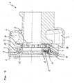
- FIG. 1 The basic structure of a first exemplary embodiment of an exhaust gas turbocharger according to the invention results from FIG. 1.
- the illustrated turbocharger 1 comprises a bearing housing 3 and a turbine housing 2 comprehensive housing, in which a shaft 4 is rotatably mounted.
- the shaft 4 carries at one end a turbine wheel 5.
- a volute 6 is formed on the side of the turbine wheel 5, which merges into an annular channel 7 in the radial direction.
- the exhaust gas turbocharger 1 comprises a diffuser 13, which makes it possible to adjust the exhaust gas inflow into the turbine by changing the turbine geometry.
- adjustable guide vanes 8 are arranged in the annular channel 7.
- the flow channels of the annular, radially flowed through by exhaust gases ring channel 7, are formed by the spaces between guide vanes 8.
- the flow channels can be changed by different angular positions of the guide vanes 8.
- the guide vanes 8 are rotatably mounted on a vane bearing ring 12 and on a by means (not shown here) spacers support and bearing ring 28 and are adjusted via an actuator (not shown here), in an unspecified manner here on an adjusting 9 acts.
- a rotational movement of the adjusting ring 9 with respect to the blade bearing ring 12 is transmitted to the guide vanes 8, in this way in a predetermined rotation range between the open and the closed position can be adjusted.
- the guide vanes 8 are secured to the blade bearing ring 12 by means of blade pins 18 which pass through the blade bearing ring 12 axially, and at their ends opposite the guide blades 8 each carrying a blade lever 11.
- FIG. 3 shows a preferred embodiment of a blade lever 11.
- the blade lever 11 shown there has a lever arm 20 which has at one end a receiving bore 19 for a blade journal 18 and at the other end a lever head 21 with a lever pin 17 protruding substantially at right angles.
- the adjusting ring 9, which serves for the simultaneous actuation of all blade lever 11, is arranged in the overlying axial plane of the circularly arranged blade lever 11.
- the adjusting ring 9 facing surface of the lever arm 20 serves as a support and axial guide surface 23 for the adjusting ring 9 (see Figure 1).
- the adjusting ring 9 engagement means which cooperate with corresponding engagement means on each of the blade lever 11 such that upon rotation of the adjusting ring 9 with respect to the blade bearing ring 12 all blade lever 11, and with them the vanes 8, to be pivoted simultaneously.
- the adjusting ring 9 carries as actuating means an actuator pin 15 operatively connected to the actuator in order to be able to control the adjusting ring 9 from outside the housing (see FIG. 2).
- the engagement means comprise in the present embodiment, as shown in the figure 1 cuboid or cube-shaped link or sliding blocks 10 with a central bore 59.
- the lever pin 17 of a blade lever 11 is inserted, so that one side of the cuboid or cube 10 is seated on the axial guide surface 23 of the lever head 21.
- the link or sliding blocks 10 engage in corresponding radially outwardly extending sliding block guides forming recesses 16 of the adjusting ring 9 a.
- the slotted or sliding blocks 10 project slightly beyond the side surface of the adjusting ring 9 facing the bearing housing 3 in the axial direction.
- the axial support or fixing of the adjusting ring 9 takes place on one side by the blade levers 11, and in particular by the axial guide surface 23 of the lever arm 20, to avoid surface contact with the turbine housing 2 and the other Side by the bearing housing 3.
- the lateral equipment for the loose plugged sliding or sliding blocks 10 form the axial guide surface 23 of the lever head 21 on the one hand and the bearing housing 3 on the other.
- the support of the adjusting ring 9 can also take place via at least three discs 24, which in addition to the loosely mounted sliding or sliding blocks 10 on respective lever pins 17 three (preferably at equal angular intervals arranged) blade lever 11 are plugged.
- At least the three sliding or sliding blocks 10 on which these halternde Lever pin 17, the three (or more) discs 24 are attached, have substantially the same axial dimensions as the adjusting ring 9, so that the corresponding discs 24, both form-fitting manner on the corresponding sliding or sliding blocks 10 and on the adjusting ring 9 under consideration of the axial play.
- the circular disks 24 in the present embodiment serve both as a support for the adjusting ring 9 and as a contact surface for the sliding or sliding blocks 10.
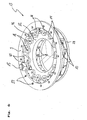
- the complete unit 13 shown in FIG. 4 can be preassembled as a cartridge.
- the bearing housing 2 is omitted as a contact surface.
- the adjusting ring 9 is supported on the blade lever 11 in the radial direction forming a rotational movement of the adjusting ring 9 relative to the blade bearing ring 12 enabling storage for the adjusting ring 9.
- the blade lever 11 have for this purpose axial lugs 14, which take over the radial bearing function. In this case, a rolling movement between the circular inner circumference of the adjusting ring 9 and acting as radial bearing surfaces circular contour portions 22 of the axial projections 14 is given.
- FIG. 5 The construction of a second exemplary embodiment of an exhaust gas turbocharger 1 according to the invention is shown in FIG. 5.
- the illustrated turbocharger 1 comprises a housing consisting of a bearing housing 3 and a turbine housing 2.
- a shaft not shown here, is rotatably mounted.
- the wave carries at one end a turbine wheel 5.
- a volute 6 is formed on the side of the turbine wheel 5, which merges into an annular channel 7 in the radial direction.
- the exhaust gas turbocharger 1 comprises a diffuser 13, which is shown from different perspectives in FIGS. 6 to 8, which makes it possible to adjust the exhaust gas inflow into the turbine by varying the turbine geometry.
- adjustable guide vanes 8 are arranged in the annular channel 7.
- the guide vanes 8 are rotatably mounted on a vane bearing ring 12 and on a support and bearing ring 28 and are adjusted via an actuator (not shown here), which acts in an unshown manner on an adjusting ring 9 here.
- a rotational movement of the adjusting ring 9 with respect to the blade bearing ring 12 is transmitted to the guide vanes 8, which can be adjusted in the manner described above in a predetermined range of rotation between an open and a closed position.
- the guide vanes 8 are attached to the blade bearing ring 12 by means of blade pins 18 as in the embodiments described above, which pass through the blade bearing ring 12 axially, and at their ends opposite the guide blades 8 each carry a blade lever 11. Furthermore, the guide vanes 8 are mounted on the support and bearing ring 28 by means of engaging in corresponding bearing bores 49 vane 48.
- the blade bearing ring 12 and the support and bearing ring 28 are held by a plurality of (in the present case three) spacers 29 at a predetermined distance from each other, which allows low-friction rotation of the guide vanes 8.
- the spacers 29 are of Fixing screws 50 held so that a modular pre-assembly of the nozzle 13 is possible.
- FIG. 8 shows a preferred embodiment of a blade lever 11.
- the blade lever 11 shown there comprises a lever arm 20 which has at one end a receiving bore 19 for a blade pin 18 and at the other end two fork-shaped projecting guide arms 47 and a recess 46 between them.
- the adjusting ring 9, which serves for the simultaneous actuation of all blade lever 11, is located in the overlying axial plane of the annularly arranged blade lever 11.
- the adjusting ring 9 facing surface of the lever arm 20 serves as a support and axial guide surface 23 for the adjusting ring 9 (FIGS. see Figures 5, 6 and 8).
- the adjusting ring 9 engagement means which cooperate with corresponding engagement means on each of the blade lever 11 such that upon rotation of the adjusting ring 9 with respect to the blade bearing ring 12 all blade lever 11, and with them the vanes 8, to be pivoted simultaneously.
- the adjusting ring 9 carries as actuating means an actuator pin 15 operatively connected to the actuator in order to be able to control the adjusting ring 9 from outside the housing (cf., FIG. 6).
- the engaging means here comprise, as shown in FIG. 7, cuboid or cube-shaped sliding blocks or sliding blocks 10 with a central bore (not visible here).
- a respective slotted or sliding block 10 In the central bore of a respective slotted or sliding block 10 is an axially projecting from the adjusting ring 9 in the figure 6 from the back visible Verstellringzapfen 57 inserted so that one side of the cuboid or cube 10 is seated on the axial in the direction of the guide vanes 8 facing annular surface 60 of the adjusting ring 9.
- the link or sliding blocks 10 engage in the corresponding radially outwardly extending sliding block guides forming recesses 46 of the blade lever 11 a.
- the adjusting ring pins 57 are executed in the present embodiment with a collar 58.
- the collar 58 serves as an axial support and guide the sliding or sliding blocks 10th
- the adjusting ring 9 is supported via the blade lever 11 in the radial direction.
- This support forms a bearing which allows rotational movements of the adjusting ring 9 relative to the blade bearing ring 12.
- the blade lever 11 have for this purpose axial lugs 14, which take over the radial bearing function. In this case, a rolling movement between the circular inner circumference of the adjusting ring 9 and acting as radial bearing surfaces circular contour portions 22 of the axial projections 14 is given.
Landscapes
- Engineering & Computer Science (AREA)
- Mechanical Engineering (AREA)
- General Engineering & Computer Science (AREA)
- Chemical & Material Sciences (AREA)
- Chemical Kinetics & Catalysis (AREA)
- General Chemical & Material Sciences (AREA)
- Combustion & Propulsion (AREA)
- Supercharger (AREA)
- Control Of Turbines (AREA)
Applications Claiming Priority (1)
| Application Number | Priority Date | Filing Date | Title |
|---|---|---|---|
| DE102004057864A DE102004057864A1 (de) | 2004-11-30 | 2004-11-30 | Abgasturbolader, Leitapparat für einen Abgasturbolader sowie Schaufelhebel für einen Leitapparat |
Publications (3)
| Publication Number | Publication Date |
|---|---|
| EP1662094A2 true EP1662094A2 (fr) | 2006-05-31 |
| EP1662094A3 EP1662094A3 (fr) | 2007-11-14 |
| EP1662094B1 EP1662094B1 (fr) | 2016-07-13 |
Family
ID=34981340
Family Applications (1)
| Application Number | Title | Priority Date | Filing Date |
|---|---|---|---|
| EP05016850.9A Active EP1662094B1 (fr) | 2004-11-30 | 2005-08-03 | Distributeur pour un turbocompresseur et turbocompresseur |
Country Status (4)
| Country | Link |
|---|---|
| US (1) | US7886536B2 (fr) |
| EP (1) | EP1662094B1 (fr) |
| JP (1) | JP4768416B2 (fr) |
| DE (1) | DE102004057864A1 (fr) |
Cited By (10)
| Publication number | Priority date | Publication date | Assignee | Title |
|---|---|---|---|---|
| EP1520959B1 (fr) * | 2002-04-26 | 2008-07-16 | BorgWarner Inc. | Turbocompresseur avec distributeur à géométrie variable |
| EP1965038A1 (fr) | 2007-03-02 | 2008-09-03 | Siemens Aktiengesellschaft | Dispositif d'actionnement pour anneau de commande des aubes de guidage d'une turbine à géométrie variable |
| WO2009065763A2 (fr) * | 2007-11-21 | 2009-05-28 | Bosch Mahle Turbo Systems Gmbh & Co. Kg | Dispositif de suralimentation |
| CN101074609B (zh) * | 2006-05-18 | 2011-04-06 | 曼柴油机欧洲股份公司 | 废气涡轮增压器的轴向进气涡轮机的导向器 |
| WO2012104366A1 (fr) * | 2011-02-02 | 2012-08-09 | Siemens Aktiengesellschaft | Ajustage angulaire accouplé d'un aubage directionnel de sortie |
| CN103109043A (zh) * | 2010-09-23 | 2013-05-15 | 博格华纳公司 | 排气涡轮增压器的vtg套筒 |
| CN103492688A (zh) * | 2011-05-10 | 2014-01-01 | 博格华纳公司 | 具有可变涡轮几何形状的涡轮增压器 |
| CN103527382A (zh) * | 2013-11-12 | 2014-01-22 | 洪雅力达水力发电设备有限责任公司 | 导水机构 |
| CN104220718A (zh) * | 2012-04-27 | 2014-12-17 | 博格华纳公司 | 排气涡轮增压器 |
| DE102022105348A1 (de) | 2022-03-08 | 2023-09-14 | Avl Schrick Gmbh | Abgasturboladerfixierung |
Families Citing this family (42)
| Publication number | Priority date | Publication date | Assignee | Title |
|---|---|---|---|---|
| DE50205993D1 (de) * | 2002-08-26 | 2006-05-04 | Borgwarner Inc | Turbolader und Schaufellagerring hierfür |
| DE60226784D1 (de) * | 2002-09-05 | 2008-07-03 | Honeywell Int Inc | Turbolader mit verstellbaren leitschaufeln |
| EP1722073B1 (fr) * | 2005-05-13 | 2013-01-23 | BorgWarner, Inc. | Anneau de commande d'un turbocompresseur à géométrie variable |
| CN101384807A (zh) * | 2006-02-16 | 2009-03-11 | 博格华纳公司 | 具有可变涡轮几何形状的涡轮增压器 |
| KR101286263B1 (ko) * | 2006-02-16 | 2013-07-15 | 보르그워너 인코퍼레이티드 | 조절가능한 가이드 블레이드, 블레이드 레버, 및 이들을 위한 조절링을 포함하는 터보차저 |
| WO2007112910A1 (fr) * | 2006-03-30 | 2007-10-11 | Borgwarner Inc. | turbocompresseur |
| DE102007005445A1 (de) | 2007-02-03 | 2008-08-07 | Bayerische Motoren Werke Aktiengesellschaft | Abgasturbolader |
| DE102007025128A1 (de) * | 2007-05-30 | 2008-12-04 | Mahle International Gmbh | Ladeeinrichtung |
| DE102007052735B4 (de) * | 2007-11-06 | 2020-08-20 | BMTS Technology GmbH & Co. KG | Ladeeinrichtung |
| US8136140B2 (en) * | 2007-11-20 | 2012-03-13 | Dish Network L.L.C. | Methods and apparatus for generating metadata utilized to filter content from a video stream using text data |
| JP4875602B2 (ja) | 2007-12-14 | 2012-02-15 | 三菱重工業株式会社 | 可変ノズル機構 |
| DE102008007670B4 (de) * | 2008-02-06 | 2021-01-07 | BMTS Technology GmbH & Co. KG | Steuerring für VTG |
| DE102009009129B4 (de) * | 2009-02-17 | 2022-11-03 | BMTS Technology GmbH & Co. KG | Turbolader mit variabler Turbinengeometrie |
| EP2317096B1 (fr) * | 2009-03-13 | 2013-05-29 | Akita Fine Blanking Co., Ltd. | Plaque de levier pour un turbocompresseur de type vgs et procédé pour produire celle-ci |
| US8231326B2 (en) | 2009-03-31 | 2012-07-31 | Nuovo Pignone S.P.A. | Nozzle adjusting mechanism and method |
| US8992164B2 (en) * | 2009-11-27 | 2015-03-31 | Borgwarner Inc. | Turbocharger |
| DE112010004596T5 (de) * | 2009-11-27 | 2013-01-24 | Borgwarner Inc. | Turbolade |
| CN102782281B (zh) * | 2010-03-03 | 2014-05-07 | 丰田自动车株式会社 | 具备涡轮增压器的内燃机的控制装置 |
| WO2012047527A2 (fr) * | 2010-09-27 | 2012-04-12 | Borgwarner Inc. | Procédé de fabrication d'un turbocompresseur |
| DE102011079579A1 (de) * | 2011-07-21 | 2013-01-24 | Bosch Mahle Turbo Systems Gmbh & Co. Kg | Variable Turbinengeometrie |
| CN103635671B (zh) * | 2011-08-08 | 2016-01-20 | 博格华纳公司 | 涡轮增压器 |
| CN103620183B (zh) | 2011-08-08 | 2017-05-03 | 博格华纳公司 | 排气涡轮增压器 |
| US10465698B2 (en) * | 2011-11-08 | 2019-11-05 | Garrett Transportation I Inc. | Compressor wheel shaft with recessed portion |
| JP6085670B2 (ja) * | 2012-04-27 | 2017-02-22 | ボーグワーナー インコーポレーテッド | 排気ガスターボチャージャ |
| JP6225171B2 (ja) * | 2012-04-27 | 2017-11-01 | ボーグワーナー インコーポレーテッド | 排気ガスターボチャージャ |
| DE112013005166T5 (de) * | 2012-11-23 | 2015-07-23 | Borgwarner Inc. | Abgasturbolader |
| KR20150102045A (ko) * | 2012-12-28 | 2015-09-04 | 보르그워너 인코퍼레이티드 | Vtg 터보차저를 위한 비대칭 액추에이터 피벗 샤프트 부싱 |
| US10240518B2 (en) * | 2013-03-15 | 2019-03-26 | Borgwarner Inc. | Integrated vane stops for variable-geometry turbocharger mechanism |
| EP3036414B1 (fr) * | 2013-08-19 | 2018-11-28 | Borgwarner Inc. | Turbocompresseur à gaz d'échappement |
| US9429033B2 (en) * | 2013-11-08 | 2016-08-30 | Honeywell International Inc. | Drive arrangement for a unison ring of a variable-vane assembly |
| US10385722B2 (en) | 2013-12-13 | 2019-08-20 | Borgwarner Inc. | Adjustment ring damper |
| TWI614410B (zh) | 2013-12-17 | 2018-02-11 | 財團法人工業技術研究院 | 進氣導葉組件 |
| CN107208539B (zh) * | 2015-02-24 | 2020-10-16 | 三菱重工发动机和增压器株式会社 | 可变喷嘴机构以及可变容量型排气涡轮增压器 |
| KR101905792B1 (ko) | 2015-09-16 | 2018-10-10 | 보르그워너 인코퍼레이티드 | 펄스 분리형 가변 터빈 구조 터보차저를 위한 카트리지 |
| US9611751B1 (en) * | 2015-09-18 | 2017-04-04 | Borgwarner Inc. | Geometry for increasing torque capacity of riveted vane lever |
| US10227887B2 (en) * | 2015-10-07 | 2019-03-12 | Hanwha Power Systems Co., Ltd. | Fluid machine with variable vanes |
| US9874106B2 (en) * | 2015-10-21 | 2018-01-23 | Borgwarner Inc. | VTG lever positive displacement press joint |
| US20180058247A1 (en) * | 2016-08-23 | 2018-03-01 | Borgwarner Inc. | Vane actuator and method of making and using the same |
| JP7078624B2 (ja) * | 2016-12-09 | 2022-05-31 | ボーグワーナー インコーポレーテッド | 可変圧縮機入口を有する圧縮機 |
| DE102020127268A1 (de) | 2019-11-13 | 2021-05-20 | Borgwarner Inc. | Turbolader mit geteiltem spiralgehäuse, der einen leitschaufelkranz mit einer mehrzahl von leitschaufeln mit asymmetrischem leitschaufelmuster aufweist, und system, das diesen enthält |
| DE102020103215A1 (de) | 2020-02-07 | 2021-08-12 | Ihi Charging Systems International Gmbh | Verstellbarer Leitapparat für einen Abgasführungsabschnitt eines Abgasturboladers, Abgasführungsabschnitt für einen Abgasturbolader und Abgasturbolader |
| US11708767B2 (en) | 2021-09-10 | 2023-07-25 | Pratt & Whitney Canada Corp. | Variable vane arm mechanism for gas turbine engine and method of operation |
Citations (4)
| Publication number | Priority date | Publication date | Assignee | Title |
|---|---|---|---|---|
| US2860827A (en) | 1953-06-08 | 1958-11-18 | Garrett Corp | Turbosupercharger |
| US4179247A (en) | 1977-01-14 | 1979-12-18 | Wrr Industries, Inc. | Turbocharger having variable area turbine nozzles |
| EP0227475A2 (fr) | 1985-12-23 | 1987-07-01 | Ishikawajima-Harima Jukogyo Kabushiki Kaisha | Turbosoufflante à gaz d'échappement avec débit de fluences variable |
| EP1357255A1 (fr) | 2002-04-26 | 2003-10-29 | BorgWarner Inc. | Turbocompresseur avec distributeur à géométrie variable |
Family Cites Families (29)
| Publication number | Priority date | Publication date | Assignee | Title |
|---|---|---|---|---|
| US3101926A (en) * | 1960-09-01 | 1963-08-27 | Garrett Corp | Variable area nozzle device |
| US4355953A (en) * | 1980-04-07 | 1982-10-26 | Guy F. Atkinson Company | Flow-adjusted hydraulic rotary machine |
| US4657476A (en) * | 1984-04-11 | 1987-04-14 | Turbotech, Inc. | Variable area turbine |
| US4659295A (en) * | 1984-04-20 | 1987-04-21 | The Garrett Corporation | Gas seal vanes of variable nozzle turbine |
| US4726744A (en) * | 1985-10-24 | 1988-02-23 | Household Manufacturing, Inc. | Tubocharger with variable vane |
| US4804316A (en) * | 1985-12-11 | 1989-02-14 | Allied-Signal Inc. | Suspension for the pivoting vane actuation mechanism of a variable nozzle turbocharger |
| JPS63147921A (ja) * | 1986-12-12 | 1988-06-20 | Isuzu Motors Ltd | 可変容量ターボ過給機のノズルベーン駆動装置の製造方法 |
| US5028208A (en) * | 1989-01-10 | 1991-07-02 | Ishikawajima-Harima Jukogyo Kabushiki Kaisha | Nozzle blade angle adjustment device for variable geometry turbocharger |
| DE3941715A1 (de) * | 1989-12-18 | 1991-06-20 | Porsche Ag | Abgasturbolader fuer eine brennkraftmaschine |
| US5549449A (en) * | 1993-07-02 | 1996-08-27 | Wrr Industries, Inc. | Turbomachinery incorporating heat transfer reduction features |
| DE19752534C1 (de) * | 1997-11-27 | 1998-10-08 | Daimler Benz Ag | Radialdurchströmte Abgasturboladerturbine |
| JP2001329851A (ja) * | 2000-05-19 | 2001-11-30 | Mitsubishi Heavy Ind Ltd | 可変容量タービンの可変ノズル機構 |
| MXPA03000497A (es) * | 2000-07-19 | 2004-09-10 | Honeywell Int Inc | Turbosobrealimentador de geometria variable con cubierta de chapa metalica. |
| DE10104176A1 (de) * | 2001-01-24 | 2002-07-25 | Mahle Gmbh | Leitschaufelverstelleinrichtung für einen Turbolader |
| US6471470B2 (en) * | 2001-02-26 | 2002-10-29 | Mitsubishi Heavy Industries, Ltd. | Vane adjustment mechanism for variable capacity turbine, and assembling method for the same |
| JP3764653B2 (ja) * | 2001-02-27 | 2006-04-12 | 三菱重工業株式会社 | 可変ノズル機構のノズル開度規制装置およびその製作方法 |
| JP3735262B2 (ja) * | 2001-02-27 | 2006-01-18 | 三菱重工業株式会社 | 可変容量タービン用可変ノズル機構およびその製作方法 |
| JP3776740B2 (ja) * | 2001-03-26 | 2006-05-17 | 三菱重工業株式会社 | 可変容量タービン構成部材の製作方法及び構成部材の構造 |
| JP2002332862A (ja) * | 2001-05-10 | 2002-11-22 | Sogi Kogyo Kk | 高クロム高ニッケル材により構成される耐久性を向上させたvgsタイプターボチャージャの排気ガイドアッセンブリ |
| US6527508B2 (en) * | 2001-08-03 | 2003-03-04 | Mark Groskreutz | Actuator crank arm design for variable nozzle turbocharger |
| EP1422399B1 (fr) * | 2001-08-03 | 2012-08-01 | Akita Fine Blanking Co., Ltd. | Procédé de fabrication de lames variables dans turbocompresseur de type vgs |
| WO2003014531A1 (fr) * | 2001-08-03 | 2003-02-20 | Akita Fine Blanking Co., Ltd. | Procede de fabrication d'element constitutif de turbocompresseur du type vgs, element constitutif fabrique selon ledit procede, ensemble de guidage de gaz d'echappement de turbocompresseur dans lequel ledit element constitutif est utilise, et turbocompresseur du type vgs equipe dudit ensemble de guidage de gaz d'echappement |
| DE10238658A1 (de) * | 2002-08-23 | 2004-03-11 | Daimlerchrysler Ag | Verdichter, insbesondere in einem Abgasturbolader für eine Brennkraftmaschine |
| US6709232B1 (en) * | 2002-09-05 | 2004-03-23 | Honeywell International Inc. | Cambered vane for use in turbochargers |
| EP1398463B1 (fr) * | 2002-09-10 | 2006-07-12 | BorgWarner Inc. | Aubes de guidage variables et turbosoufflante avec ces aubes |
| US6814540B2 (en) * | 2002-10-22 | 2004-11-09 | Carrier Corporation | Rotating vane diffuser for a centrifugal compressor |
| DE50209301D1 (de) * | 2002-11-11 | 2007-03-08 | Borgwarner Inc | Leitgitter variabler Geometrie |
| ATE423893T1 (de) * | 2003-12-31 | 2009-03-15 | Honeywell Int Inc | Abgasturbolader |
| US7137778B2 (en) * | 2004-04-12 | 2006-11-21 | Borgwarner Inc. | Variable turbine geometry turbocharger |
-
2004
- 2004-11-30 DE DE102004057864A patent/DE102004057864A1/de not_active Ceased
-
2005
- 2005-08-03 EP EP05016850.9A patent/EP1662094B1/fr active Active
- 2005-11-03 US US11/265,926 patent/US7886536B2/en active Active
- 2005-11-25 JP JP2005340655A patent/JP4768416B2/ja not_active Expired - Fee Related
Patent Citations (4)
| Publication number | Priority date | Publication date | Assignee | Title |
|---|---|---|---|---|
| US2860827A (en) | 1953-06-08 | 1958-11-18 | Garrett Corp | Turbosupercharger |
| US4179247A (en) | 1977-01-14 | 1979-12-18 | Wrr Industries, Inc. | Turbocharger having variable area turbine nozzles |
| EP0227475A2 (fr) | 1985-12-23 | 1987-07-01 | Ishikawajima-Harima Jukogyo Kabushiki Kaisha | Turbosoufflante à gaz d'échappement avec débit de fluences variable |
| EP1357255A1 (fr) | 2002-04-26 | 2003-10-29 | BorgWarner Inc. | Turbocompresseur avec distributeur à géométrie variable |
Cited By (14)
| Publication number | Priority date | Publication date | Assignee | Title |
|---|---|---|---|---|
| EP1520959B1 (fr) * | 2002-04-26 | 2008-07-16 | BorgWarner Inc. | Turbocompresseur avec distributeur à géométrie variable |
| CN101074609B (zh) * | 2006-05-18 | 2011-04-06 | 曼柴油机欧洲股份公司 | 废气涡轮增压器的轴向进气涡轮机的导向器 |
| EP1965038A1 (fr) | 2007-03-02 | 2008-09-03 | Siemens Aktiengesellschaft | Dispositif d'actionnement pour anneau de commande des aubes de guidage d'une turbine à géométrie variable |
| WO2008107280A1 (fr) * | 2007-03-02 | 2008-09-12 | Siemens Aktiengesellschaft | Entraînement de la bague de réglage pour des appareils directeurs d'admission dans des machines de détente de gaz chaud |
| US8845279B2 (en) | 2007-11-21 | 2014-09-30 | Bosch Mahle Turbo Systems Gmbh & Co. Kg | Supercharger device |
| WO2009065763A2 (fr) * | 2007-11-21 | 2009-05-28 | Bosch Mahle Turbo Systems Gmbh & Co. Kg | Dispositif de suralimentation |
| CN103109043A (zh) * | 2010-09-23 | 2013-05-15 | 博格华纳公司 | 排气涡轮增压器的vtg套筒 |
| WO2012104366A1 (fr) * | 2011-02-02 | 2012-08-09 | Siemens Aktiengesellschaft | Ajustage angulaire accouplé d'un aubage directionnel de sortie |
| CN103492688A (zh) * | 2011-05-10 | 2014-01-01 | 博格华纳公司 | 具有可变涡轮几何形状的涡轮增压器 |
| CN103492688B (zh) * | 2011-05-10 | 2016-02-10 | 博格华纳公司 | 具有可变涡轮几何形状的涡轮增压器 |
| CN104220718A (zh) * | 2012-04-27 | 2014-12-17 | 博格华纳公司 | 排气涡轮增压器 |
| CN104220718B (zh) * | 2012-04-27 | 2017-03-29 | 博格华纳公司 | 排气涡轮增压器及其vtg套筒 |
| CN103527382A (zh) * | 2013-11-12 | 2014-01-22 | 洪雅力达水力发电设备有限责任公司 | 导水机构 |
| DE102022105348A1 (de) | 2022-03-08 | 2023-09-14 | Avl Schrick Gmbh | Abgasturboladerfixierung |
Also Published As
| Publication number | Publication date |
|---|---|
| US20060112690A1 (en) | 2006-06-01 |
| JP2006161811A (ja) | 2006-06-22 |
| EP1662094B1 (fr) | 2016-07-13 |
| EP1662094A3 (fr) | 2007-11-14 |
| JP4768416B2 (ja) | 2011-09-07 |
| DE102004057864A1 (de) | 2006-06-01 |
| US7886536B2 (en) | 2011-02-15 |
Similar Documents
| Publication | Publication Date | Title |
|---|---|---|
| EP1662094B1 (fr) | Distributeur pour un turbocompresseur et turbocompresseur | |
| EP2002127B1 (fr) | Dispositif directeur à pré-tourbillonnement | |
| DE102016100900B4 (de) | Verstellvorrichtung für einen Abgasturbolader und Abgasturbolader | |
| EP1811134A1 (fr) | Dispositif de guidage réglable | |
| DE102005048814B4 (de) | Gasturbine und Baugruppe für eine Gasturbine | |
| EP1977084B1 (fr) | Dispositif de direction pouvant etre deplace | |
| EP2018480B1 (fr) | Turbocompresseur | |
| DE112010004597B4 (de) | Turbolader mit variabler Turbinengeometrie | |
| DE102008007670B4 (de) | Steuerring für VTG | |
| DE1033965B (de) | Lader fuer Brennkraftmaschinen od. dgl. | |
| EP1984601A1 (fr) | Turbocompresseur pourvu d'aubes directrices réglables, d'un levier d'aubes et d'une bague de réglage à cet effet | |
| WO2006060925A1 (fr) | Dispositif directeur pour turbine a gaz d'echappement | |
| DE112016004554T5 (de) | Betätigungsvorrichtung für variable Statorschaufeln | |
| DE102012106789B4 (de) | Verstellbarer Leitapparat für eine Turbine, Turbine für einen Abgasturbolader und Abgasturbolader | |
| WO2018007000A1 (fr) | Roue à aubes d'un turbocompresseur à gaz d'échappement, turbocompresseur à gaz d'échappement et procédé d'équilibrage d'un ensemble tournant pour un turbocompresseur à gaz d'échappement | |
| EP1357255A1 (fr) | Turbocompresseur avec distributeur à géométrie variable | |
| DE60305011T2 (de) | Verbesserte schaufelausführung zur verwendung in turboladern mit variabler geometrie | |
| WO2007090731A2 (fr) | Appareil directeur, et élément d'amortissement pour un appareil directeur | |
| EP1635041B1 (fr) | Callage de superchargeur | |
| EP2730751B1 (fr) | Dispositif de réglage d'aubes directrices d'une turbine à gaz | |
| EP0130408B1 (fr) | Dispositif pour régler la section d'entrée de la turbine d'une turbosoufflante | |
| DE10313167B4 (de) | Leitschaufelverstellung für Turbolader mit variabler Turbinengeometrie | |
| DE102004023210B4 (de) | Abgasturbolader für eine Brennkraftmaschine mit variabler Turbinengeometrie | |
| EP2317081B1 (fr) | Turbines et/ou compresseurs à géométrie variable | |
| DE102004023211A1 (de) | Abgasturbolader für eine Brennkraftmaschine mit variabler Turbinengeometrie |
Legal Events
| Date | Code | Title | Description |
|---|---|---|---|
| PUAI | Public reference made under article 153(3) epc to a published international application that has entered the european phase |
Free format text: ORIGINAL CODE: 0009012 |
|
| AK | Designated contracting states |
Kind code of ref document: A2 Designated state(s): AT BE BG CH CY CZ DE DK EE ES FI FR GB GR HU IE IS IT LI LT LU LV MC NL PL PT RO SE SI SK TR |
|
| AX | Request for extension of the european patent |
Extension state: AL BA HR MK YU |
|
| PUAL | Search report despatched |
Free format text: ORIGINAL CODE: 0009013 |
|
| AK | Designated contracting states |
Kind code of ref document: A3 Designated state(s): AT BE BG CH CY CZ DE DK EE ES FI FR GB GR HU IE IS IT LI LT LU LV MC NL PL PT RO SE SI SK TR |
|
| AX | Request for extension of the european patent |
Extension state: AL BA HR MK YU |
|
| RIC1 | Information provided on ipc code assigned before grant |
Ipc: F02C 6/12 20060101ALI20071011BHEP Ipc: F01D 17/16 20060101AFI20051005BHEP |
|
| 17P | Request for examination filed |
Effective date: 20080418 |
|
| 17Q | First examination report despatched |
Effective date: 20080623 |
|
| AKX | Designation fees paid |
Designated state(s): DE FR GB IT NL |
|
| GRAP | Despatch of communication of intention to grant a patent |
Free format text: ORIGINAL CODE: EPIDOSNIGR1 |
|
| INTG | Intention to grant announced |
Effective date: 20160205 |
|
| GRAS | Grant fee paid |
Free format text: ORIGINAL CODE: EPIDOSNIGR3 |
|
| GRAA | (expected) grant |
Free format text: ORIGINAL CODE: 0009210 |
|
| AK | Designated contracting states |
Kind code of ref document: B1 Designated state(s): DE FR GB IT NL |
|
| REG | Reference to a national code |
Ref country code: GB Ref legal event code: FG4D Free format text: NOT ENGLISH |
|
| REG | Reference to a national code |
Ref country code: FR Ref legal event code: PLFP Year of fee payment: 12 |
|
| REG | Reference to a national code |
Ref country code: DE Ref legal event code: R096 Ref document number: 502005015279 Country of ref document: DE |
|
| REG | Reference to a national code |
Ref country code: NL Ref legal event code: FP |
|
| REG | Reference to a national code |
Ref country code: DE Ref legal event code: R097 Ref document number: 502005015279 Country of ref document: DE |
|
| PLBE | No opposition filed within time limit |
Free format text: ORIGINAL CODE: 0009261 |
|
| STAA | Information on the status of an ep patent application or granted ep patent |
Free format text: STATUS: NO OPPOSITION FILED WITHIN TIME LIMIT |
|
| 26N | No opposition filed |
Effective date: 20170418 |
|
| REG | Reference to a national code |
Ref country code: FR Ref legal event code: PLFP Year of fee payment: 13 |
|
| REG | Reference to a national code |
Ref country code: FR Ref legal event code: PLFP Year of fee payment: 14 |
|
| PGFP | Annual fee paid to national office [announced via postgrant information from national office to epo] |
Ref country code: NL Payment date: 20190730 Year of fee payment: 15 |
|
| PGFP | Annual fee paid to national office [announced via postgrant information from national office to epo] |
Ref country code: IT Payment date: 20190826 Year of fee payment: 15 |
|
| PGFP | Annual fee paid to national office [announced via postgrant information from national office to epo] |
Ref country code: GB Payment date: 20200729 Year of fee payment: 16 Ref country code: FR Payment date: 20200716 Year of fee payment: 16 |
|
| REG | Reference to a national code |
Ref country code: NL Ref legal event code: MM Effective date: 20200901 |
|
| PG25 | Lapsed in a contracting state [announced via postgrant information from national office to epo] |
Ref country code: IT Free format text: LAPSE BECAUSE OF NON-PAYMENT OF DUE FEES Effective date: 20200803 |
|
| PG25 | Lapsed in a contracting state [announced via postgrant information from national office to epo] |
Ref country code: NL Free format text: LAPSE BECAUSE OF NON-PAYMENT OF DUE FEES Effective date: 20200901 |
|
| GBPC | Gb: european patent ceased through non-payment of renewal fee |
Effective date: 20210803 |
|
| PG25 | Lapsed in a contracting state [announced via postgrant information from national office to epo] |
Ref country code: GB Free format text: LAPSE BECAUSE OF NON-PAYMENT OF DUE FEES Effective date: 20210803 Ref country code: FR Free format text: LAPSE BECAUSE OF NON-PAYMENT OF DUE FEES Effective date: 20210831 |
|
| P01 | Opt-out of the competence of the unified patent court (upc) registered |
Effective date: 20230327 |
|
| PGFP | Annual fee paid to national office [announced via postgrant information from national office to epo] |
Ref country code: DE Payment date: 20230711 Year of fee payment: 19 |