US9611751B1 - Geometry for increasing torque capacity of riveted vane lever - Google Patents

Geometry for increasing torque capacity of riveted vane lever Download PDF

Info

Publication number
US9611751B1
US9611751B1 US14/858,223 US201514858223A US9611751B1 US 9611751 B1 US9611751 B1 US 9611751B1 US 201514858223 A US201514858223 A US 201514858223A US 9611751 B1 US9611751 B1 US 9611751B1
Authority
US
United States
Prior art keywords
vane
cylindrical
lever
opening
lobed
Prior art date
Legal status (The legal status is an assumption and is not a legal conclusion. Google has not performed a legal analysis and makes no representation as to the accuracy of the status listed.)
Active
Application number
US14/858,223
Other versions
US20170081975A1 (en
Inventor
John Zagone
Eli Morgan
Greg Williams
Current Assignee (The listed assignees may be inaccurate. Google has not performed a legal analysis and makes no representation or warranty as to the accuracy of the list.)
BorgWarner Inc
Original Assignee
BorgWarner Inc
Priority date (The priority date is an assumption and is not a legal conclusion. Google has not performed a legal analysis and makes no representation as to the accuracy of the date listed.)
Filing date
Publication date
Application filed by BorgWarner Inc filed Critical BorgWarner Inc
Assigned to BORGWARNER INC. reassignment BORGWARNER INC. ASSIGNMENT OF ASSIGNORS INTEREST (SEE DOCUMENT FOR DETAILS). Assignors: MORGAN, Eli, WILLIAMS, GREG, ZAGONE, JOHN
Priority to US14/858,223 priority Critical patent/US9611751B1/en
Priority to EP16770159.8A priority patent/EP3350419B1/en
Priority to CN201680053244.3A priority patent/CN108026783B/en
Priority to JP2018513829A priority patent/JP2018532067A/en
Priority to PCT/US2016/051219 priority patent/WO2017048611A1/en
Priority to KR1020187009060A priority patent/KR20180054652A/en
Publication of US20170081975A1 publication Critical patent/US20170081975A1/en
Publication of US9611751B1 publication Critical patent/US9611751B1/en
Application granted granted Critical
Active legal-status Critical Current
Anticipated expiration legal-status Critical

Links

Images

Classifications

    • FMECHANICAL ENGINEERING; LIGHTING; HEATING; WEAPONS; BLASTING
    • F01MACHINES OR ENGINES IN GENERAL; ENGINE PLANTS IN GENERAL; STEAM ENGINES
    • F01DNON-POSITIVE DISPLACEMENT MACHINES OR ENGINES, e.g. STEAM TURBINES
    • F01D17/00Regulating or controlling by varying flow
    • F01D17/10Final actuators
    • F01D17/12Final actuators arranged in stator parts
    • F01D17/14Final actuators arranged in stator parts varying effective cross-sectional area of nozzles or guide conduits
    • F01D17/16Final actuators arranged in stator parts varying effective cross-sectional area of nozzles or guide conduits by means of nozzle vanes
    • F01D17/165Final actuators arranged in stator parts varying effective cross-sectional area of nozzles or guide conduits by means of nozzle vanes for radial flow, i.e. the vanes turning around axes which are essentially parallel to the rotor centre line
    • FMECHANICAL ENGINEERING; LIGHTING; HEATING; WEAPONS; BLASTING
    • F01MACHINES OR ENGINES IN GENERAL; ENGINE PLANTS IN GENERAL; STEAM ENGINES
    • F01DNON-POSITIVE DISPLACEMENT MACHINES OR ENGINES, e.g. STEAM TURBINES
    • F01D17/00Regulating or controlling by varying flow
    • F01D17/10Final actuators
    • F01D17/12Final actuators arranged in stator parts
    • F01D17/14Final actuators arranged in stator parts varying effective cross-sectional area of nozzles or guide conduits
    • F01D17/16Final actuators arranged in stator parts varying effective cross-sectional area of nozzles or guide conduits by means of nozzle vanes
    • FMECHANICAL ENGINEERING; LIGHTING; HEATING; WEAPONS; BLASTING
    • F01MACHINES OR ENGINES IN GENERAL; ENGINE PLANTS IN GENERAL; STEAM ENGINES
    • F01DNON-POSITIVE DISPLACEMENT MACHINES OR ENGINES, e.g. STEAM TURBINES
    • F01D9/00Stators
    • F01D9/02Nozzles; Nozzle boxes; Stator blades; Guide conduits, e.g. individual nozzles
    • F01D9/04Nozzles; Nozzle boxes; Stator blades; Guide conduits, e.g. individual nozzles forming ring or sector
    • F01D9/041Nozzles; Nozzle boxes; Stator blades; Guide conduits, e.g. individual nozzles forming ring or sector using blades
    • FMECHANICAL ENGINEERING; LIGHTING; HEATING; WEAPONS; BLASTING
    • F02COMBUSTION ENGINES; HOT-GAS OR COMBUSTION-PRODUCT ENGINE PLANTS
    • F02CGAS-TURBINE PLANTS; AIR INTAKES FOR JET-PROPULSION PLANTS; CONTROLLING FUEL SUPPLY IN AIR-BREATHING JET-PROPULSION PLANTS
    • F02C6/00Plural gas-turbine plants; Combinations of gas-turbine plants with other apparatus; Adaptations of gas- turbine plants for special use
    • F02C6/04Gas-turbine plants providing heated or pressurised working fluid for other apparatus, e.g. without mechanical power output
    • F02C6/10Gas-turbine plants providing heated or pressurised working fluid for other apparatus, e.g. without mechanical power output supplying working fluid to a user, e.g. a chemical process, which returns working fluid to a turbine of the plant
    • F02C6/12Turbochargers, i.e. plants for augmenting mechanical power output of internal-combustion piston engines by increase of charge pressure
    • FMECHANICAL ENGINEERING; LIGHTING; HEATING; WEAPONS; BLASTING
    • F02COMBUSTION ENGINES; HOT-GAS OR COMBUSTION-PRODUCT ENGINE PLANTS
    • F02CGAS-TURBINE PLANTS; AIR INTAKES FOR JET-PROPULSION PLANTS; CONTROLLING FUEL SUPPLY IN AIR-BREATHING JET-PROPULSION PLANTS
    • F02C9/00Controlling gas-turbine plants; Controlling fuel supply in air- breathing jet-propulsion plants
    • F02C9/16Control of working fluid flow
    • F02C9/20Control of working fluid flow by throttling; by adjusting vanes
    • FMECHANICAL ENGINEERING; LIGHTING; HEATING; WEAPONS; BLASTING
    • F05INDEXING SCHEMES RELATING TO ENGINES OR PUMPS IN VARIOUS SUBCLASSES OF CLASSES F01-F04
    • F05DINDEXING SCHEME FOR ASPECTS RELATING TO NON-POSITIVE-DISPLACEMENT MACHINES OR ENGINES, GAS-TURBINES OR JET-PROPULSION PLANTS
    • F05D2220/00Application
    • F05D2220/40Application in turbochargers
    • FMECHANICAL ENGINEERING; LIGHTING; HEATING; WEAPONS; BLASTING
    • F05INDEXING SCHEMES RELATING TO ENGINES OR PUMPS IN VARIOUS SUBCLASSES OF CLASSES F01-F04
    • F05DINDEXING SCHEME FOR ASPECTS RELATING TO NON-POSITIVE-DISPLACEMENT MACHINES OR ENGINES, GAS-TURBINES OR JET-PROPULSION PLANTS
    • F05D2230/00Manufacture
    • F05D2230/60Assembly methods
    • FMECHANICAL ENGINEERING; LIGHTING; HEATING; WEAPONS; BLASTING
    • F05INDEXING SCHEMES RELATING TO ENGINES OR PUMPS IN VARIOUS SUBCLASSES OF CLASSES F01-F04
    • F05DINDEXING SCHEME FOR ASPECTS RELATING TO NON-POSITIVE-DISPLACEMENT MACHINES OR ENGINES, GAS-TURBINES OR JET-PROPULSION PLANTS
    • F05D2240/00Components
    • F05D2240/10Stators
    • F05D2240/12Fluid guiding means, e.g. vanes

Definitions

  • the field to which the disclosure generally relates to includes vane levers and vane shafts for a turbine.
  • a turbocharger may include variable turbine geometry using vanes in front of a turbine wheel.
  • a number of variations may include a product comprising: a vane lever comprising a first end; a second end; a top surface; and a bottom surface; and an opening defined by an inner surface which extends through the top surface and the bottom surface of the second end, and wherein at least a portion of the inner surface comprises a non-cylindrical, multi-lobed shape.
  • a number of variations may include a vane pack assembly comprising: an upper vane ring; a lower vane ring; a plurality of vane components each having a vane shaft and a vane interposed between the upper vane ring and the lower vane ring; an adjustment ring surrounding a portion of the upper vane ring having a plurality of openings; and a plurality of vane levers each having a non-cylindrical, multi-lobed opening defined by an inner surface at a second end of the vane lever, wherein the non-cylindrical, multi-lobed opening surrounds a portion of the vane shaft and wherein the first end of the vane lever attaches to the adjustment ring.
  • a number of variations may include a method of joining a vane lever and a vane shaft of a vane pack assembly together comprising: providing a vane lever having a non-cylindrical, multi-lobed opening defined by an inner surface; fitting the vane lever onto a vane shaft; and riveting the vane shaft to the vane lever.
  • FIG. 1 illustrates a perspective view of a vane lever according to a number of variations.
  • FIG. 2 illustrates a perspective view of a vane lever according to a number of variations.
  • FIG. 3 illustrates a top view of a vane lever according to a number of variations.
  • FIG. 4 illustrates a perspective view of a vane lever according to a number of variations.
  • FIG. 5 illustrates a top view of a vane lever according to a number of variations.
  • FIG. 6 illustrates a perspective view of a vane lever according to a number of variations.
  • FIG. 7 illustrates a perspective view of vane lever according to a number of variations.
  • FIG. 8 illustrated a perspective bottom view of a vane lever according to a number of variations.
  • FIG. 9 illustrates a perspective view of a vane lever according to a number of variations.
  • FIG. 10 illustrates a perspective view of a vane component according to a number of variations.
  • FIG. 11 illustrates a perspective view of a vane component according to a number of variations.
  • FIG. 12 illustrates a top view of a vane lever positioned onto a vane shaft according to a number of variations.
  • FIG. 13 illustrates an exploded view of a vane pack assembly according to a number of variations.
  • FIG. 14 illustrates a perspective view of a vane pack according to a number of variations.
  • FIG. 15 illustrates a close-up perspective view of a vane pack assembly according to a number of variations.
  • FIG. 16 illustrates a close-up perspective view of a vane pack assembly according to a number of variations.
  • FIG. 17 illustrates a close-up perspective view of a vane pack assembly according to a number of variations.
  • FIG. 18 illustrates a close-up perspective view of a vane pack assembly according to a number of variations.
  • FIG. 19 illustrates a section view of a vane pack assembly according to a number of variations.
  • FIG. 20 illustrates a perspective view of a vane component according to a number of variations.
  • FIG. 21 illustrates a perspective view of a vane component according to a number of variations.
  • a variable turbine geometry (VTG) turbocharger may be used to expand the usable flow rate range of an engine while at the same time maintaining a high level of efficiency.
  • a VTG turbocharger may regulate the turbine output by changing the inflow angle and the inflow speed at the turbine inlet. The change in the inflow angle and inflow speed at the turbine inlet may be done using a vane pack assembly 30 , a variation of which is illustrated in FIG. 14 . As temperatures and aero loads of the VTG turbocharger are increased, the torque transfer capability through the vane levers 32 and the vane shafts 64 of the vane pack assembly 30 may need to be increased.
  • a cylindrical (or non-cylindrical) vane shaft and non-circular, multi-lobed lever opening may be joined together using a riveting process which may form a high torque capacity joint which may withstand the temperatures and aero loads of the VTG turbocharger, as will be discussed below.
  • a vane lever 32 may include a first end 34 , a second end 36 , a top surface 38 , and a bottom surface 40 .
  • the vane lever 32 may also include an opening 44 which may extend through the top surface 38 and the bottom surface 40 at the second end 36 of the vane lever 32 , and which may be defined by an inner surface 52 of the vane lever 32 .
  • the inner surface 52 may be constructed and arranged to accommodate a portion of the outer perimeter of the vane shaft 64 .
  • the vane lever opening 44 may be any number of non-cylindrical multi-lobed shapes.
  • the vane lever opening 44 may include a four sided multi-lobe interface 46 including, but not limited to, a diamond-like or square shape, through the entire interface from the top surface 38 to the bottom surface 40 , a variation of which is illustrated in FIG. 1 .
  • the vane lever opening 44 may be a three sided multi-lobe interface 48 including, but not limited to, a triangular or trilobe shape, through the entire interface from the top surface 38 to the bottom surface 40 , a variation of which is illustrated in FIG. 2 .
  • the vane lever opening 44 may transition from cylindrical 49 at the bottom surface 40 to non-cylindrical shapes 46 , 48 described above and hereafter at the top surface 38 , variations of which are illustrated in FIGS. 3-7 and 9 .
  • the vane lever opening 44 may include a four sided multi-lobe interface 46 at the top surface 38 , transitioning to a circular interface 49 at the bottom surface 40 , variations of which are illustrated in FIGS. 3, 4, and 9 .
  • the vane lever opening 44 may include a three sided multi-lobe interface 48 on the top surface 38 , transitioning to a circular interface 49 at the bottom surface 40 , variations of which are illustrated in FIGS. 5 and 6 .
  • the vane lever opening 44 may include a knurled four sided multi-lobe interface 46 at the top surface 38 , transitioning to a circular interface 49 at the bottom surface 40 , a variation of which is illustrated in FIG. 7 .
  • the top edge 50 of the inner surface 52 may be rounded or chamfered 54 , variations of which are illustrated in FIGS. 1-2 .
  • the top edge 50 of the inner surface 52 may include a groove 56 at each of the lobes 58 , variations of which are illustrated in FIGS. 3-6 and 9 .
  • the top edge 50 of the inner surface 52 may include a plurality of ridges or grooves 60 which may extend around the perimeter of the top edge 50 , a variation of which is illustrated in FIG. 7 .
  • the bottom edge 51 of the inner surface 52 may also be rounded or may include a chamfer.
  • the vane lever 32 may also include a tab 42 which may extend downward from the first end 34 and may be constructed and arranged to mate with an opening/cutout 90 in an adjustment ring 88 , as will be discussed hereafter.
  • the tab 42 may include a cutout or grooved surface 43 , a variation of which is illustrated in FIG. 8 .
  • the bottom surface 40 may include a standoff 100 which may be located between the first end 34 and the second end 36 , a variation of which is also illustrated in FIG. 8 .
  • the standoff 100 may be constructed and arranged so that it may sit on the top surface 89 of the adjustment ring 88 , variations of which are illustrated in FIGS. 15 and 19 .
  • the first end 34 of the vane lever 32 may be constructed and arranged as a fork end 91 having a first and second protrusion 93 .
  • the fork end 91 of the vane lever 32 may be constructed and arranged to attach to an adjustment ring 88 , as will be discussed hereafter.
  • vane lever configurations may include any of the above vane lever opening 44 configurations without departing from the spirit and scope of the invention.
  • a vane component 62 may include a vane 66 and a vane shaft 64 . Any number of vane 66 configurations may be used.
  • the vane shaft 64 may extend through the vane 66 so that the vane 66 may rotate around the vane shaft 64 .
  • a first portion 68 of the vane shaft 64 may be constructed and arranged to extend within an opening 81 in a lower vane ring 80 , as will be discussed hereafter.
  • a second portion 70 of the vane shaft 64 may be constructed and arranged to extend through an opening 83 in an upper vane ring 82 , as will be discussed hereafter.
  • the vane shaft 64 may be cylindrical and may include a shouldered step 72 which may be constructed and arranged to fit within the vane lever opening 44 , as will be discussed hereafter.
  • the shouldered step 72 may be cylindrical 74 , a variation of which is illustrated in FIG. 10 , and may be subsequently deformed to conform to a non-circular vane lever opening 44 interface, variations of which are illustrated in FIGS. 20-21 .
  • the shouldered step 72 may be non-cylindrical 76 to mate with the non-cylindrical shape of the vane lever opening 44 , a variation of which is illustrated in FIG. 11 , and may be subsequently deformed to conform to the non-circular lever interface.
  • a plurality of vane components 62 may be spaced circumferentially between the lower vane ring 80 and the upper vane ring 82 so that the vanes 66 are positioned between the lower vane ring 80 and the upper vane ring 82 and so that the shouldered step 72 extends above the upper vane ring 82 .
  • the upper vane ring 82 may include a stepped portion 84 which may extend around the outer perimeter 86 of the upper vane ring 82 and may be constructed and arranged to accommodate a portion of an adjustment ring 88 .
  • the first end 34 of the vane lever 32 may be attached to the adjustment ring 88 .
  • the adjustment ring 88 may include a plurality of cutouts/openings 90 which may be constructed and arranged to accommodate a tab 42 on the vane lever 32 , a variation of which is illustrated in FIG. 15 , or a block 102 which may be located within the cutout/opening 90 and which may be constructed and arranged to accommodate the tab 42 , a variation of which is illustrated in FIG. 17 , which may secure the adjustment ring 88 to the upper vane ring 82 .
  • the vane levers 32 may be positioned onto the vane shafts 64 so that the vane shaft 64 extends through the vane lever openings 44 and so that the lever tabs 42 extend through the cutouts/openings 90 (or blocks 102 ) on the adjustment ring 88 , variations of which are illustrated in FIGS. 15 and 17 .
  • a vane lever 32 having a fork end 91 may be positioned between the adjustment ring 88 and the upper vane ring 82 so that the first and second protrusions 93 surround a pin 104 which may be riveted or welded to the adjustment ring 88 to attach the vane lever 32 to the adjustment ring 88 , a variation of which is illustrated in FIG. 16 .
  • a combination of pins and rotating blocks may be used to secure the vane lever 32 to the adjustment ring 88 . It is noted that any number of attachment methods between the vane lever 32 and the adjustment ring 88 may be used.
  • a press-fit may be used for accurate positioning if desired, a variation of which is illustrated in FIG. 12 .
  • Press-fitting the vane lever 32 onto the vane shaft 64 may cause irregular radial material deformation at the top edge 50 of the inner surface 52 which may further increase torque capacity before riveting.
  • external fixturing may be used to accomplish vane lever 32 to vane shaft 64 orientation for assemblies using vane shafts 64 having a cylindrical 74 shouldered step 72 .
  • vane lever 32 to vane shaft 64 orientation may be accomplished using similar non-cylindrical shapes 46 , 76 on the inner surface 52 and the shouldered step 72 of the vane shaft 64 , variations of which are illustrated in FIGS. 1 and 11 .
  • the vane shafts 64 may be riveted 92 to the vane levers 32 to secure the vane shafts 64 in place.
  • the riveting of the vane shafts 64 may cause the material of the vane shaft 64 to form into the shape of the inner surface 52 so that the vane shaft 64 contours the shape of the inner surface 52 , variations of which are illustrated in FIGS. 20 and 21 .
  • the interface between the non-cylindrical inner surface 52 and the dilated vane shaft 78 material may provide additional grip between the vane lever 32 and the vane shaft 64 which may increase the torque capacity of the joint.
  • any number of combinations of the above geometries and differing edge conditions at the top of the rivet interface may be used to accommodate the riveting process. It is noted that more irregular or aggressive geometries may be used with advanced riveting processes capable of exaggerated deformations of the vane shaft material.
  • Variation 1 may include a product comprising: a vane lever comprising a first end; a second end; a top surface; and a bottom surface; and an opening defined by an inner surface which extends through the top surface and the bottom surface of the second end, and wherein at least a portion of the inner surface comprises a non-cylindrical, multi-lobed shape.
  • Variation 2 may include a product as set forth in Variation 1 wherein the inner surface transitions from a cylindrical shape at the bottom surface to the non-cylindrical, multi-lobed shape at the top surface.
  • Variation 3 may include a product as set forth in Variation 1 wherein a top edge of the inner surface is at least one of rounded or includes a groove at each of the lobes
  • Variation 4 may include a product as set forth in Variation 1 wherein a top edge of the inner surface includes a plurality of ridges.
  • Variation 5 may include a product as set forth in any of Variations 1-4 further comprising a vane component, wherein the vane component comprises a vane rotatably mounted to a vane shaft, wherein the vane shaft includes a stepped portion; and wherein the stepped portion extends through the non-cylindrical, multi-lobed opening of the vane lever and is attached to the vane lever.
  • the vane component comprises a vane rotatably mounted to a vane shaft, wherein the vane shaft includes a stepped portion; and wherein the stepped portion extends through the non-cylindrical, multi-lobed opening of the vane lever and is attached to the vane lever.
  • Variation 6 may include a product as set forth in Variation 5 wherein the stepped portion is cylindrical.
  • Variation 7 may include a product as set forth in Variation 5 wherein the stepped portion is non-cylindrical.
  • Variation 8 may include a product as set forth in any of Variations 5-7 wherein the vane shaft is riveted to the vane lever.
  • Variation 9 may include a vane pack assembly comprising: an upper vane ring; a lower vane ring; a plurality of vane components each having a vane shaft and a vane interposed between the upper vane ring and the lower vane ring; an adjustment ring surrounding a portion of the upper vane ring having a plurality of openings; and a plurality of vane levers each having a non-cylindrical, multi-lobed opening defined by an inner surface at a second end of the vane lever, wherein the non-cylindrical, multi-lobed opening surrounds a portion of the vane shaft and wherein the first end of the vane lever attaches to the adjustment ring.
  • Variation 10 may include a vane pack assembly as set forth in Variation 9 wherein a portion of the vane shaft is riveted to the vane lever and conforms to the shape of the inner surface.
  • Variation 11 may include a vane pack assembly as set forth in any of Variations 9-10 wherein the non-cylindrical, multi-lobed opening is at least one of a diamond shape, a square shape, a triangular shape, or other polygon shape.
  • Variation 12 may include a vane pack assembly as set forth in any of Variations 9-11 wherein the inner surface has at least one of a rounded or a chamfered top edge.
  • Variation 13 may include a vane pack assembly as set forth in any of Variations 9-11 wherein the inner surface includes a top edge having a groove at each lobe.
  • Variation 14 may include a vane pack assembly as set forth in any of Variations 9-11 wherein the inner surface includes a top edge having a plurality of ridges.
  • Variation 15 may include a vane pack assembly as set forth in any of Variations 9-14 where the vane shaft includes a stepped portion which is constructed and arranged to extend within the vane lever opening.
  • Variation 16 may include a vane pack assembly as set forth in Variation 15 wherein the stepped portion is cylindrical.
  • Variation 17 may include a vane pack assembly as set forth in Variation 15 wherein the stepped portion is non-cylindrical.
  • Variation 18 may include a method of joining a vane lever and a vane shaft of a vane pack assembly together comprising: providing a vane lever having a non-cylindrical, multi-lobed opening defined by an inner surface; fitting the vane lever onto a vane shaft; and riveting the vane shaft to the vane lever.
  • Variation 19 may include a method as set forth in Variation 18 wherein the vane shaft further comprises a stepped portion having a non-cylindrical multi-lobed shape to match the non-cylindrical, multi-lobed opening for orienting the vane lever during assembly.
  • Variation 20 may include a method as set forth in any of Variations 18-19 wherein a top edge of the inner surface is at least one of rounded or grooved causing the vane shaft to conform to the shape of the inner surface when riveted.

Abstract

A number of variations may include a product comprising: a vane lever comprising a first end; a second end; a top surface; and a bottom surface; and an opening defined by an inner surface which extends through the top surface and the bottom surface of the second end, and wherein at least a portion of the inner surface comprises a non-cylindrical, multi-lobed shape.

Description

TECHNICAL FIELD
The field to which the disclosure generally relates to includes vane levers and vane shafts for a turbine.
BACKGROUND
A turbocharger may include variable turbine geometry using vanes in front of a turbine wheel.
SUMMARY OF ILLUSTRATIVE VARIATIONS
A number of variations may include a product comprising: a vane lever comprising a first end; a second end; a top surface; and a bottom surface; and an opening defined by an inner surface which extends through the top surface and the bottom surface of the second end, and wherein at least a portion of the inner surface comprises a non-cylindrical, multi-lobed shape.
A number of variations may include a vane pack assembly comprising: an upper vane ring; a lower vane ring; a plurality of vane components each having a vane shaft and a vane interposed between the upper vane ring and the lower vane ring; an adjustment ring surrounding a portion of the upper vane ring having a plurality of openings; and a plurality of vane levers each having a non-cylindrical, multi-lobed opening defined by an inner surface at a second end of the vane lever, wherein the non-cylindrical, multi-lobed opening surrounds a portion of the vane shaft and wherein the first end of the vane lever attaches to the adjustment ring.
A number of variations may include a method of joining a vane lever and a vane shaft of a vane pack assembly together comprising: providing a vane lever having a non-cylindrical, multi-lobed opening defined by an inner surface; fitting the vane lever onto a vane shaft; and riveting the vane shaft to the vane lever.
Other illustrative variations within the scope of the invention will become apparent from the detailed description provided hereinafter. It should be understood that the detailed description and specific examples, while disclosing variations within the scope of the invention, are intended for purposes of illustration only and are not intended to limit the scope of the invention.
BRIEF DESCRIPTION OF THE DRAWINGS
Select examples of variations within the scope of the invention will become more fully understood from the detailed description and the accompanying drawings, wherein:
FIG. 1 illustrates a perspective view of a vane lever according to a number of variations.
FIG. 2 illustrates a perspective view of a vane lever according to a number of variations.
FIG. 3 illustrates a top view of a vane lever according to a number of variations.
FIG. 4 illustrates a perspective view of a vane lever according to a number of variations.
FIG. 5 illustrates a top view of a vane lever according to a number of variations.
FIG. 6 illustrates a perspective view of a vane lever according to a number of variations.
FIG. 7 illustrates a perspective view of vane lever according to a number of variations.
FIG. 8 illustrated a perspective bottom view of a vane lever according to a number of variations.
FIG. 9 illustrates a perspective view of a vane lever according to a number of variations.
FIG. 10 illustrates a perspective view of a vane component according to a number of variations.
FIG. 11 illustrates a perspective view of a vane component according to a number of variations.
FIG. 12 illustrates a top view of a vane lever positioned onto a vane shaft according to a number of variations.
FIG. 13 illustrates an exploded view of a vane pack assembly according to a number of variations.
FIG. 14 illustrates a perspective view of a vane pack according to a number of variations.
FIG. 15 illustrates a close-up perspective view of a vane pack assembly according to a number of variations.
FIG. 16 illustrates a close-up perspective view of a vane pack assembly according to a number of variations.
FIG. 17 illustrates a close-up perspective view of a vane pack assembly according to a number of variations.
FIG. 18 illustrates a close-up perspective view of a vane pack assembly according to a number of variations.
FIG. 19 illustrates a section view of a vane pack assembly according to a number of variations.
FIG. 20 illustrates a perspective view of a vane component according to a number of variations.
FIG. 21 illustrates a perspective view of a vane component according to a number of variations.
DETAILED DESCRIPTION OF ILLUSTRATIVE VARIATIONS
The following description of the variations is merely illustrative in nature and is in no way intended to limit the scope of the invention, its application, or uses.
A variable turbine geometry (VTG) turbocharger may be used to expand the usable flow rate range of an engine while at the same time maintaining a high level of efficiency. A VTG turbocharger may regulate the turbine output by changing the inflow angle and the inflow speed at the turbine inlet. The change in the inflow angle and inflow speed at the turbine inlet may be done using a vane pack assembly 30, a variation of which is illustrated in FIG. 14. As temperatures and aero loads of the VTG turbocharger are increased, the torque transfer capability through the vane levers 32 and the vane shafts 64 of the vane pack assembly 30 may need to be increased. In a number of variations, a cylindrical (or non-cylindrical) vane shaft and non-circular, multi-lobed lever opening may be joined together using a riveting process which may form a high torque capacity joint which may withstand the temperatures and aero loads of the VTG turbocharger, as will be discussed below.
Referring to FIGS. 1-9, in a number of variations, a vane lever 32 may include a first end 34, a second end 36, a top surface 38, and a bottom surface 40. The vane lever 32 may also include an opening 44 which may extend through the top surface 38 and the bottom surface 40 at the second end 36 of the vane lever 32, and which may be defined by an inner surface 52 of the vane lever 32. The inner surface 52 may be constructed and arranged to accommodate a portion of the outer perimeter of the vane shaft 64. The vane lever opening 44 may be any number of non-cylindrical multi-lobed shapes. In one variation, the vane lever opening 44 may include a four sided multi-lobe interface 46 including, but not limited to, a diamond-like or square shape, through the entire interface from the top surface 38 to the bottom surface 40, a variation of which is illustrated in FIG. 1. In another variation, the vane lever opening 44 may be a three sided multi-lobe interface 48 including, but not limited to, a triangular or trilobe shape, through the entire interface from the top surface 38 to the bottom surface 40, a variation of which is illustrated in FIG. 2. In a number of variations, the vane lever opening 44 may transition from cylindrical 49 at the bottom surface 40 to non-cylindrical shapes 46, 48 described above and hereafter at the top surface 38, variations of which are illustrated in FIGS. 3-7 and 9. In one variation, the vane lever opening 44 may include a four sided multi-lobe interface 46 at the top surface 38, transitioning to a circular interface 49 at the bottom surface 40, variations of which are illustrated in FIGS. 3, 4, and 9. In another variation, the vane lever opening 44 may include a three sided multi-lobe interface 48 on the top surface 38, transitioning to a circular interface 49 at the bottom surface 40, variations of which are illustrated in FIGS. 5 and 6. In another variation, the vane lever opening 44 may include a knurled four sided multi-lobe interface 46 at the top surface 38, transitioning to a circular interface 49 at the bottom surface 40, a variation of which is illustrated in FIG. 7. In one variation, the top edge 50 of the inner surface 52 may be rounded or chamfered 54, variations of which are illustrated in FIGS. 1-2. In another variation, the top edge 50 of the inner surface 52 may include a groove 56 at each of the lobes 58, variations of which are illustrated in FIGS. 3-6 and 9. In yet another variation, the top edge 50 of the inner surface 52 may include a plurality of ridges or grooves 60 which may extend around the perimeter of the top edge 50, a variation of which is illustrated in FIG. 7. Referring to FIG. 8, in a number of variations, the bottom edge 51 of the inner surface 52 may also be rounded or may include a chamfer.
Referring to FIGS. 1-8, in one variation, the vane lever 32 may also include a tab 42 which may extend downward from the first end 34 and may be constructed and arranged to mate with an opening/cutout 90 in an adjustment ring 88, as will be discussed hereafter. In a number of variations, the tab 42 may include a cutout or grooved surface 43, a variation of which is illustrated in FIG. 8. The bottom surface 40 may include a standoff 100 which may be located between the first end 34 and the second end 36, a variation of which is also illustrated in FIG. 8. The standoff 100 may be constructed and arranged so that it may sit on the top surface 89 of the adjustment ring 88, variations of which are illustrated in FIGS. 15 and 19.
Referring to FIG. 9, in another variation, the first end 34 of the vane lever 32 may be constructed and arranged as a fork end 91 having a first and second protrusion 93. The fork end 91 of the vane lever 32 may be constructed and arranged to attach to an adjustment ring 88, as will be discussed hereafter.
It is noted that any number of vane lever configurations may include any of the above vane lever opening 44 configurations without departing from the spirit and scope of the invention.
Referring to FIGS. 10-11, in a number of variations, a vane component 62 may include a vane 66 and a vane shaft 64. Any number of vane 66 configurations may be used. The vane shaft 64 may extend through the vane 66 so that the vane 66 may rotate around the vane shaft 64. A first portion 68 of the vane shaft 64 may be constructed and arranged to extend within an opening 81 in a lower vane ring 80, as will be discussed hereafter. A second portion 70 of the vane shaft 64 may be constructed and arranged to extend through an opening 83 in an upper vane ring 82, as will be discussed hereafter. In a number of variations, the vane shaft 64 may be cylindrical and may include a shouldered step 72 which may be constructed and arranged to fit within the vane lever opening 44, as will be discussed hereafter. In one variation, the shouldered step 72 may be cylindrical 74, a variation of which is illustrated in FIG. 10, and may be subsequently deformed to conform to a non-circular vane lever opening 44 interface, variations of which are illustrated in FIGS. 20-21. In another variation, the shouldered step 72 may be non-cylindrical 76 to mate with the non-cylindrical shape of the vane lever opening 44, a variation of which is illustrated in FIG. 11, and may be subsequently deformed to conform to the non-circular lever interface.
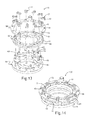
Referring to FIGS. 13-14, in a number of variations, a plurality of vane components 62 may be spaced circumferentially between the lower vane ring 80 and the upper vane ring 82 so that the vanes 66 are positioned between the lower vane ring 80 and the upper vane ring 82 and so that the shouldered step 72 extends above the upper vane ring 82. In a number of variations, the upper vane ring 82 may include a stepped portion 84 which may extend around the outer perimeter 86 of the upper vane ring 82 and may be constructed and arranged to accommodate a portion of an adjustment ring 88.
Referring to FIGS. 15-17, in a number of variations, the first end 34 of the vane lever 32 may be attached to the adjustment ring 88. In one variation, the adjustment ring 88 may include a plurality of cutouts/openings 90 which may be constructed and arranged to accommodate a tab 42 on the vane lever 32, a variation of which is illustrated in FIG. 15, or a block 102 which may be located within the cutout/opening 90 and which may be constructed and arranged to accommodate the tab 42, a variation of which is illustrated in FIG. 17, which may secure the adjustment ring 88 to the upper vane ring 82. In this variation, the vane levers 32 may be positioned onto the vane shafts 64 so that the vane shaft 64 extends through the vane lever openings 44 and so that the lever tabs 42 extend through the cutouts/openings 90 (or blocks 102) on the adjustment ring 88, variations of which are illustrated in FIGS. 15 and 17. In another variation, a vane lever 32 having a fork end 91 may be positioned between the adjustment ring 88 and the upper vane ring 82 so that the first and second protrusions 93 surround a pin 104 which may be riveted or welded to the adjustment ring 88 to attach the vane lever 32 to the adjustment ring 88, a variation of which is illustrated in FIG. 16. In another variation, a combination of pins and rotating blocks may be used to secure the vane lever 32 to the adjustment ring 88. It is noted that any number of attachment methods between the vane lever 32 and the adjustment ring 88 may be used.
In one variation, a press-fit may be used for accurate positioning if desired, a variation of which is illustrated in FIG. 12. Press-fitting the vane lever 32 onto the vane shaft 64 may cause irregular radial material deformation at the top edge 50 of the inner surface 52 which may further increase torque capacity before riveting. In a number of variations, external fixturing may be used to accomplish vane lever 32 to vane shaft 64 orientation for assemblies using vane shafts 64 having a cylindrical 74 shouldered step 72. In another variation, vane lever 32 to vane shaft 64 orientation may be accomplished using similar non-cylindrical shapes 46, 76 on the inner surface 52 and the shouldered step 72 of the vane shaft 64, variations of which are illustrated in FIGS. 1 and 11.
Referring to FIGS. 18-21, in a number of variations, the vane shafts 64 may be riveted 92 to the vane levers 32 to secure the vane shafts 64 in place. The riveting of the vane shafts 64 may cause the material of the vane shaft 64 to form into the shape of the inner surface 52 so that the vane shaft 64 contours the shape of the inner surface 52, variations of which are illustrated in FIGS. 20 and 21. The interface between the non-cylindrical inner surface 52 and the dilated vane shaft 78 material may provide additional grip between the vane lever 32 and the vane shaft 64 which may increase the torque capacity of the joint.
Any number of combinations of the above geometries and differing edge conditions at the top of the rivet interface may be used to accommodate the riveting process. It is noted that more irregular or aggressive geometries may be used with advanced riveting processes capable of exaggerated deformations of the vane shaft material.
The following description of variants is only illustrative of components, elements, acts, products and methods considered to be within the scope of the invention and are not in any way intended to limit such scope by what is specifically disclosed or not expressly set forth. The components, elements, acts, products and methods as described herein may be combined and rearranged other than as expressly described herein and still are considered to be within the scope of the invention.
Variation 1 may include a product comprising: a vane lever comprising a first end; a second end; a top surface; and a bottom surface; and an opening defined by an inner surface which extends through the top surface and the bottom surface of the second end, and wherein at least a portion of the inner surface comprises a non-cylindrical, multi-lobed shape.
Variation 2 may include a product as set forth in Variation 1 wherein the inner surface transitions from a cylindrical shape at the bottom surface to the non-cylindrical, multi-lobed shape at the top surface.
Variation 3 may include a product as set forth in Variation 1 wherein a top edge of the inner surface is at least one of rounded or includes a groove at each of the lobes
Variation 4 may include a product as set forth in Variation 1 wherein a top edge of the inner surface includes a plurality of ridges.
Variation 5 may include a product as set forth in any of Variations 1-4 further comprising a vane component, wherein the vane component comprises a vane rotatably mounted to a vane shaft, wherein the vane shaft includes a stepped portion; and wherein the stepped portion extends through the non-cylindrical, multi-lobed opening of the vane lever and is attached to the vane lever.
Variation 6 may include a product as set forth in Variation 5 wherein the stepped portion is cylindrical.
Variation 7 may include a product as set forth in Variation 5 wherein the stepped portion is non-cylindrical.
Variation 8 may include a product as set forth in any of Variations 5-7 wherein the vane shaft is riveted to the vane lever.
Variation 9 may include a vane pack assembly comprising: an upper vane ring; a lower vane ring; a plurality of vane components each having a vane shaft and a vane interposed between the upper vane ring and the lower vane ring; an adjustment ring surrounding a portion of the upper vane ring having a plurality of openings; and a plurality of vane levers each having a non-cylindrical, multi-lobed opening defined by an inner surface at a second end of the vane lever, wherein the non-cylindrical, multi-lobed opening surrounds a portion of the vane shaft and wherein the first end of the vane lever attaches to the adjustment ring.
Variation 10 may include a vane pack assembly as set forth in Variation 9 wherein a portion of the vane shaft is riveted to the vane lever and conforms to the shape of the inner surface.
Variation 11 may include a vane pack assembly as set forth in any of Variations 9-10 wherein the non-cylindrical, multi-lobed opening is at least one of a diamond shape, a square shape, a triangular shape, or other polygon shape.
Variation 12 may include a vane pack assembly as set forth in any of Variations 9-11 wherein the inner surface has at least one of a rounded or a chamfered top edge.
Variation 13 may include a vane pack assembly as set forth in any of Variations 9-11 wherein the inner surface includes a top edge having a groove at each lobe.
Variation 14 may include a vane pack assembly as set forth in any of Variations 9-11 wherein the inner surface includes a top edge having a plurality of ridges.
Variation 15 may include a vane pack assembly as set forth in any of Variations 9-14 where the vane shaft includes a stepped portion which is constructed and arranged to extend within the vane lever opening.
Variation 16 may include a vane pack assembly as set forth in Variation 15 wherein the stepped portion is cylindrical.
Variation 17 may include a vane pack assembly as set forth in Variation 15 wherein the stepped portion is non-cylindrical.
Variation 18 may include a method of joining a vane lever and a vane shaft of a vane pack assembly together comprising: providing a vane lever having a non-cylindrical, multi-lobed opening defined by an inner surface; fitting the vane lever onto a vane shaft; and riveting the vane shaft to the vane lever.
Variation 19 may include a method as set forth in Variation 18 wherein the vane shaft further comprises a stepped portion having a non-cylindrical multi-lobed shape to match the non-cylindrical, multi-lobed opening for orienting the vane lever during assembly.
Variation 20 may include a method as set forth in any of Variations 18-19 wherein a top edge of the inner surface is at least one of rounded or grooved causing the vane shaft to conform to the shape of the inner surface when riveted.
The above description of select variations within the scope of the invention is merely illustrative in nature and, thus, variations or variants thereof are not to be regarded as a departure from the spirit and scope of the invention.

Claims (16)

What is claimed is:
1. A product comprising: a vane lever comprising a first end; a second end; a top surface; and a bottom surface; and an opening which extends through the top surface and the bottom surface of the second end, wherein the opening is defined by an inner surface and at least one intervening surface between the inner surface and the top surface, wherein at least a portion of the opening comprises a non-cylindrical, multi-lobed shape; and wherein the intervening surface extends between the top surface and the inner wall at each of the lobes only.
2. The product of claim 1 wherein the intervening surface is at least one of rounded, chamfered, grooved, or a plurality of ridges.
3. The product of claim 1 further comprising a vane component, wherein the vane component comprises a vane rotatably mounted to a vane shaft, wherein the vane shaft includes a stepped portion; and wherein the stepped portion extends through the non-cylindrical, multi-lobed opening of the vane lever and is attached to the vane lever.
4. The product of claim 3 wherein the stepped portion is cylindrical.
5. The product of claim 3 wherein the stepped portion is non-cylindrical.
6. The product of claim 3 wherein the vane shaft is riveted to the vane lever.
7. A vane pack assembly comprising:
an upper vane ring;
a lower vane ring;
a plurality of vane components each having a vane shaft and a vane interposed between the upper vane ring and the lower vane ring;
an adjustment ring surrounding a portion of the upper vane ring having a plurality of openings; and
a plurality of vane levers each having a non-cylindrical, multi-lobed opening which extends between a top surface and a bottom surface at a second end of the vane lever, wherein the non-cylindrical, multi-lobed opening is defined by an inner surface and at least one intervening surface between the inner surface and the top surface of the vane lever, wherein the non-cylindrical, multi-lobed opening surrounds a portion of the vane shaft and wherein a first end of the vane lever attaches to adjustment ring; and the intervening surface extends between the inner surface and the top surface at each of the lobes only.
8. The vane pack assembly of claim 7 wherein the non-cylindrical, multi-lobed opening is at least one of a diamond shape, a square shape, a triangular shape, or other polygon shape.
9. The vane pack assembly of claim 7 wherein the intervening surface is at least one of rounded, chamfered, ridged, or grooved.
10. The vane pack assembly of claim 7 wherein the intervening surface is a plurality of ridges.
11. The vane pack assembly of claim 7 where the vane shaft includes a stepped portion which is constructed and arranged to extend within the vane lever opening.
12. The vane pack assembly of claim 11 wherein the stepped portion is cylindrical.
13. The vane pack assembly of claim 11 wherein the stepped portion is non-cylindrical.
14. A method of joining a vane lever and a vane shaft of a vane pack assembly together comprising: providing a vane lever having a non-cylindrical, multi-lobed opening defined by an inner surface and at least one intervening surface between a top surface of the vane lever and the inner surface, wherein the at least one intervening surface is at each of the lobes only; fitting the vane lever onto a vane shaft; and riveting the vane shaft to the vane lever.
15. The method of claim 14 wherein the vane shaft further comprises a stepped portion having a non-cylindrical multi-lobed shape to match the non-cylindrical, multi-lobed opening for orienting the vane lever during assembly.
16. A product comprising: a vane lever comprising a first end; a second end; a top surface; and a bottom surface; and an opening which extends through the top surface and the bottom surface of the second end, wherein the opening is defined by an inner surface and at least one intervening surface between the inner surface and the top surface, wherein at least a portion of the opening comprises a non-cylindrical, multi-lobed shape; and wherein the opening transitions from a cylindrical shape at the bottom surface to the non-cylindrical, multi-lobed shape at the top surface.
US14/858,223 2015-09-18 2015-09-18 Geometry for increasing torque capacity of riveted vane lever Active US9611751B1 (en)

Priority Applications (6)

Application Number Priority Date Filing Date Title
US14/858,223 US9611751B1 (en) 2015-09-18 2015-09-18 Geometry for increasing torque capacity of riveted vane lever
PCT/US2016/051219 WO2017048611A1 (en) 2015-09-18 2016-09-12 Geometry for increasing torque capacity of riveted vane lever
CN201680053244.3A CN108026783B (en) 2015-09-18 2016-09-12 Product for forming a blade assembly, blade assembly and related method
JP2018513829A JP2018532067A (en) 2015-09-18 2016-09-12 Geometry to increase the torque capacity of the rivet vane lever
EP16770159.8A EP3350419B1 (en) 2015-09-18 2016-09-12 Vane lever for a variable-geometry turbocharger with geometry for increased torque capacity
KR1020187009060A KR20180054652A (en) 2015-09-18 2016-09-12 Geometry to increase the torque capacity of the rivet vane lever

Applications Claiming Priority (1)

Application Number Priority Date Filing Date Title
US14/858,223 US9611751B1 (en) 2015-09-18 2015-09-18 Geometry for increasing torque capacity of riveted vane lever

Publications (2)

Publication Number Publication Date
US20170081975A1 US20170081975A1 (en) 2017-03-23
US9611751B1 true US9611751B1 (en) 2017-04-04

Family

ID=56979680

Family Applications (1)

Application Number Title Priority Date Filing Date
US14/858,223 Active US9611751B1 (en) 2015-09-18 2015-09-18 Geometry for increasing torque capacity of riveted vane lever

Country Status (6)

Country Link
US (1) US9611751B1 (en)
EP (1) EP3350419B1 (en)
JP (1) JP2018532067A (en)
KR (1) KR20180054652A (en)
CN (1) CN108026783B (en)
WO (1) WO2017048611A1 (en)

Cited By (2)

* Cited by examiner, † Cited by third party
Publication number Priority date Publication date Assignee Title
US20180311906A1 (en) * 2015-11-13 2018-11-01 Nec Platforms, Ltd. Fixing object, fixation item, fixing method, and assessment method
US11076530B2 (en) 2019-03-15 2021-08-03 Honda Motor Co., Ltd. Riveted joint and method of forming the same

Families Citing this family (5)

* Cited by examiner, † Cited by third party
Publication number Priority date Publication date Assignee Title
US20170234153A1 (en) * 2016-02-17 2017-08-17 Borgwarner Inc. Guide Apparatus for a Turbocharger Including a Vane Lever Integrated Adjustment Ring Axial Travel Stop
US10590795B2 (en) * 2017-10-17 2020-03-17 United Technologies Corporation Vane arm with tri-wedge circular pocket
US10619508B2 (en) * 2017-11-03 2020-04-14 Borgwarner, Inc. Variable turbine geometry vane lever
DE102017222209A1 (en) * 2017-12-07 2019-06-13 MTU Aero Engines AG Guide vane connection and turbomachine
DE102021120382A1 (en) * 2021-08-05 2023-02-09 MTU Aero Engines AG Connection device for an adjustable blade of a gas turbine and gas turbine

Citations (15)

* Cited by examiner, † Cited by third party
Publication number Priority date Publication date Assignee Title
US4979874A (en) * 1989-06-19 1990-12-25 United Technologies Corporation Variable van drive mechanism
US5092723A (en) * 1989-06-30 1992-03-03 Vsi Corporation Engine clip bolt
US5492446A (en) * 1994-12-15 1996-02-20 General Electric Company Self-aligning variable stator vane
US5690459A (en) * 1996-05-29 1997-11-25 Textron Inc. Plate and riveted stud assembly
US6019574A (en) * 1998-08-13 2000-02-01 General Electric Company Mismatch proof variable stator vane
US6699010B2 (en) * 2000-05-19 2004-03-02 Mitsubishi Heavy Industries, Ltd. Nozzle adjustment mechanism for variable-capacity turbine
US7223066B2 (en) * 2003-05-27 2007-05-29 Rolls-Royce Plc Variable vane arrangement for a turbomachine
US20090074569A1 (en) * 2007-09-13 2009-03-19 Snecma Lever for rotating a turbomachine variable-pitch stator vane about its pivot
US20100260597A1 (en) 2009-04-10 2010-10-14 Lorrain Sausse Variable-vane assembly having fixed guide pins for unison ring
US7815390B2 (en) * 2004-09-30 2010-10-19 Faurecia Innenraum Systeme Gmbh Rivet or screw connection of a plastic part to a further part
US7886536B2 (en) * 2004-11-30 2011-02-15 Borgwarner Inc. Exhaust-gas turbocharger, regulating device for an exhaust-gas turbocharger and vane lever for a regulating device
KR20110108206A (en) 2010-03-26 2011-10-05 (주)계양정밀 Variable nozzle device of turbocharger
US8104280B2 (en) * 2009-03-13 2012-01-31 Akita Fine Blanking Co., Ltd. Lever plate in VGS type turbocharger and method of manufacturing the same
WO2013163018A1 (en) 2012-04-27 2013-10-31 Borgwarner Inc. Exhaust-gas turbocharger
US8668443B2 (en) 2010-01-08 2014-03-11 Honeywell International Inc. Variable-vane assembly having unison ring guided radially by rollers and fixed members, and restrained axially by one or more fixed axial stops

Family Cites Families (9)

* Cited by examiner, † Cited by third party
Publication number Priority date Publication date Assignee Title
JP3735262B2 (en) * 2001-02-27 2006-01-18 三菱重工業株式会社 Variable nozzle mechanism for variable capacity turbine and manufacturing method thereof
WO2003014531A1 (en) * 2001-08-03 2003-02-20 Akita Fine Blanking Co., Ltd. Method of manufacturing component member in vgs type turbo charger, component member manufactured by the method, exhaust guide assembly of vgs type turbo charger using the component member, and vgs type turbo charger incorporating the exhaust guide assembly
EP1811135A1 (en) * 2006-01-23 2007-07-25 ABB Turbo Systems AG Variable guiding device
FR2897120B1 (en) * 2006-02-03 2012-10-19 Snecma TANK PIVOT WITH TURBOMACHINE VARIABLE SETTING ANGLE AND DEVICE FOR CONTROLLING SUCH A DAWN
GB0915786D0 (en) * 2009-09-10 2009-10-07 Rolls Royce Plc Variable stator vane assemblies
US9903220B2 (en) * 2010-03-03 2018-02-27 Borgwarner Inc. Cost reduced variable geometry turbocharger with stamped adjustment ring assembly
CN102383872A (en) * 2011-10-18 2012-03-21 湖南天雁机械有限责任公司 Turbocharger variable nozzle with limit pin
DE102012201135A1 (en) * 2012-01-26 2013-08-01 Bosch Mahle Turbo Systems Gmbh & Co. Kg Charging device i.e. exhaust gas turbocharger for combustion engine, has guide vane lever rotatably connected to guide vane pin and to vane lever pin, and adjusting ring connected to blade lever pin by positive connections
EP2971597B1 (en) * 2013-03-13 2021-12-29 Raytheon Technologies Corporation Machined vane arm of a variable vane actuation system

Patent Citations (15)

* Cited by examiner, † Cited by third party
Publication number Priority date Publication date Assignee Title
US4979874A (en) * 1989-06-19 1990-12-25 United Technologies Corporation Variable van drive mechanism
US5092723A (en) * 1989-06-30 1992-03-03 Vsi Corporation Engine clip bolt
US5492446A (en) * 1994-12-15 1996-02-20 General Electric Company Self-aligning variable stator vane
US5690459A (en) * 1996-05-29 1997-11-25 Textron Inc. Plate and riveted stud assembly
US6019574A (en) * 1998-08-13 2000-02-01 General Electric Company Mismatch proof variable stator vane
US6699010B2 (en) * 2000-05-19 2004-03-02 Mitsubishi Heavy Industries, Ltd. Nozzle adjustment mechanism for variable-capacity turbine
US7223066B2 (en) * 2003-05-27 2007-05-29 Rolls-Royce Plc Variable vane arrangement for a turbomachine
US7815390B2 (en) * 2004-09-30 2010-10-19 Faurecia Innenraum Systeme Gmbh Rivet or screw connection of a plastic part to a further part
US7886536B2 (en) * 2004-11-30 2011-02-15 Borgwarner Inc. Exhaust-gas turbocharger, regulating device for an exhaust-gas turbocharger and vane lever for a regulating device
US20090074569A1 (en) * 2007-09-13 2009-03-19 Snecma Lever for rotating a turbomachine variable-pitch stator vane about its pivot
US8104280B2 (en) * 2009-03-13 2012-01-31 Akita Fine Blanking Co., Ltd. Lever plate in VGS type turbocharger and method of manufacturing the same
US20100260597A1 (en) 2009-04-10 2010-10-14 Lorrain Sausse Variable-vane assembly having fixed guide pins for unison ring
US8668443B2 (en) 2010-01-08 2014-03-11 Honeywell International Inc. Variable-vane assembly having unison ring guided radially by rollers and fixed members, and restrained axially by one or more fixed axial stops
KR20110108206A (en) 2010-03-26 2011-10-05 (주)계양정밀 Variable nozzle device of turbocharger
WO2013163018A1 (en) 2012-04-27 2013-10-31 Borgwarner Inc. Exhaust-gas turbocharger

Cited By (3)

* Cited by examiner, † Cited by third party
Publication number Priority date Publication date Assignee Title
US20180311906A1 (en) * 2015-11-13 2018-11-01 Nec Platforms, Ltd. Fixing object, fixation item, fixing method, and assessment method
US11141929B2 (en) * 2015-11-13 2021-10-12 Nec Platforms, Ltd. Fixing object, fixation item, fixing method, and assessment method
US11076530B2 (en) 2019-03-15 2021-08-03 Honda Motor Co., Ltd. Riveted joint and method of forming the same

Also Published As

Publication number Publication date
JP2018532067A (en) 2018-11-01
US20170081975A1 (en) 2017-03-23
EP3350419A1 (en) 2018-07-25
KR20180054652A (en) 2018-05-24
WO2017048611A1 (en) 2017-03-23
CN108026783B (en) 2021-01-05
EP3350419B1 (en) 2022-09-07
CN108026783A (en) 2018-05-11

Similar Documents

Publication Publication Date Title
US9611751B1 (en) Geometry for increasing torque capacity of riveted vane lever
US8403645B2 (en) Turbofan flow path trenches
KR101994511B1 (en) Nozzle ring
US9284969B2 (en) Thermal expansion joint connection for sheet metal assembly
EP3112692B1 (en) Centrifugal compressor, turbocharger with said centrifugal compressor, and method for manufacturing said centrifugal compressor
CN111828384B (en) Fan of jet engine
US9874106B2 (en) VTG lever positive displacement press joint
US9429031B2 (en) Hub for radial housing of a helical ring of a turbomachine with variable-pitch blades and assembly comprising such a hub
EP2530298B1 (en) Propeller for a hydraulic machine, hydraulic machine provided with such a propeller and method for assembling such a propeller
JP2013053623A (en) Shaft assembly for gas turbine engine
US10156244B2 (en) Fan assembly
US10502133B2 (en) Fastener cover for flowpath fasteners
US10293918B2 (en) Device for fixing blades with variable pitch of a non-streamlined turbomachine propeller
RU2630919C1 (en) Rotor forth stage impeller of high-pressure compressor (hpc) of turbojet engine (versions), hpc rotor impeller disc, hpc rotor impeller blade, hpc rotor impeller blade ring
CN109196249A (en) The torque-converters of impeller housing including the extension for being connected to engine drive plate
TWI687610B (en) Sprocket wheel for a bicycle drive
FR3094906B1 (en) METHOD FOR MANUFACTURING A STATOR BLADE ELEMENT FOR A TURBOMACHINE AND TOOLS FOR ITS IMPLEMENTATION
US9927015B2 (en) Method of forming torque converter stator
US6237221B1 (en) Method of fixing impeller blades of a torque converter
US10655634B2 (en) Multi-piece compressor wheel
RU2630924C1 (en) Rotor eighth stage impeller of high-pressure compressor (hpc) of turbojet engine (versions), hpc rotor impeller disc, hpc rotor impeller blade, hpc rotor impeller blade ring
RU2603380C1 (en) Gas turbine engine low pressure compressor rotor impeller (versions)
RU2630925C1 (en) Ninth stage impeller wheel of high pressure compressor (hpc) rotor of turbocharger engine, hpc rotor impeller wheel disc, hpc rotor impeller wheel blade, hpc rotor impeller wheel blade ring
RU2630921C1 (en) Impeller wheel of third stage of high pressure compressor (hpc) rotor of turbocharger engine (variants), hpc rotor impeller wheel disc, hpc rotor impeller wheel blade, hpc rotor impeller wheel blade ring
US8944769B2 (en) Blade assembly with improved joint strength

Legal Events

Date Code Title Description
AS Assignment

Owner name: BORGWARNER INC., MICHIGAN

Free format text: ASSIGNMENT OF ASSIGNORS INTEREST;ASSIGNORS:ZAGONE, JOHN;MORGAN, ELI;WILLIAMS, GREG;SIGNING DATES FROM 20150910 TO 20150911;REEL/FRAME:036600/0144

FEPP Fee payment procedure

Free format text: PAYOR NUMBER ASSIGNED (ORIGINAL EVENT CODE: ASPN); ENTITY STATUS OF PATENT OWNER: LARGE ENTITY

STCF Information on status: patent grant

Free format text: PATENTED CASE

MAFP Maintenance fee payment

Free format text: PAYMENT OF MAINTENANCE FEE, 4TH YEAR, LARGE ENTITY (ORIGINAL EVENT CODE: M1551); ENTITY STATUS OF PATENT OWNER: LARGE ENTITY

Year of fee payment: 4