EP2002127B1 - Dispositif directeur à pré-tourbillonnement - Google Patents
Dispositif directeur à pré-tourbillonnement Download PDFInfo
- Publication number
- EP2002127B1 EP2002127B1 EP07701890A EP07701890A EP2002127B1 EP 2002127 B1 EP2002127 B1 EP 2002127B1 EP 07701890 A EP07701890 A EP 07701890A EP 07701890 A EP07701890 A EP 07701890A EP 2002127 B1 EP2002127 B1 EP 2002127B1
- Authority
- EP
- European Patent Office
- Prior art keywords
- guide
- vane
- preswirl
- guide device
- axis
- Prior art date
- Legal status (The legal status is an assumption and is not a legal conclusion. Google has not performed a legal analysis and makes no representation as to the accuracy of the status listed.)
- Expired - Fee Related
Links
Images

Classifications
-
- F—MECHANICAL ENGINEERING; LIGHTING; HEATING; WEAPONS; BLASTING
- F04—POSITIVE - DISPLACEMENT MACHINES FOR LIQUIDS; PUMPS FOR LIQUIDS OR ELASTIC FLUIDS
- F04D—NON-POSITIVE-DISPLACEMENT PUMPS
- F04D29/00—Details, component parts, or accessories
- F04D29/40—Casings; Connections of working fluid
- F04D29/42—Casings; Connections of working fluid for radial or helico-centrifugal pumps
- F04D29/44—Fluid-guiding means, e.g. diffusers
- F04D29/46—Fluid-guiding means, e.g. diffusers adjustable
- F04D29/462—Fluid-guiding means, e.g. diffusers adjustable especially adapted for elastic fluid pumps
-
- F—MECHANICAL ENGINEERING; LIGHTING; HEATING; WEAPONS; BLASTING
- F04—POSITIVE - DISPLACEMENT MACHINES FOR LIQUIDS; PUMPS FOR LIQUIDS OR ELASTIC FLUIDS
- F04D—NON-POSITIVE-DISPLACEMENT PUMPS
- F04D29/00—Details, component parts, or accessories
- F04D29/40—Casings; Connections of working fluid
- F04D29/42—Casings; Connections of working fluid for radial or helico-centrifugal pumps
- F04D29/44—Fluid-guiding means, e.g. diffusers
- F04D29/46—Fluid-guiding means, e.g. diffusers adjustable
-
- F—MECHANICAL ENGINEERING; LIGHTING; HEATING; WEAPONS; BLASTING
- F01—MACHINES OR ENGINES IN GENERAL; ENGINE PLANTS IN GENERAL; STEAM ENGINES
- F01D—NON-POSITIVE DISPLACEMENT MACHINES OR ENGINES, e.g. STEAM TURBINES
- F01D17/00—Regulating or controlling by varying flow
- F01D17/10—Final actuators
- F01D17/12—Final actuators arranged in stator parts
- F01D17/14—Final actuators arranged in stator parts varying effective cross-sectional area of nozzles or guide conduits
- F01D17/16—Final actuators arranged in stator parts varying effective cross-sectional area of nozzles or guide conduits by means of nozzle vanes
-
- F—MECHANICAL ENGINEERING; LIGHTING; HEATING; WEAPONS; BLASTING
- F04—POSITIVE - DISPLACEMENT MACHINES FOR LIQUIDS; PUMPS FOR LIQUIDS OR ELASTIC FLUIDS
- F04D—NON-POSITIVE-DISPLACEMENT PUMPS
- F04D29/00—Details, component parts, or accessories
- F04D29/40—Casings; Connections of working fluid
- F04D29/42—Casings; Connections of working fluid for radial or helico-centrifugal pumps
- F04D29/4206—Casings; Connections of working fluid for radial or helico-centrifugal pumps especially adapted for elastic fluid pumps
- F04D29/4213—Casings; Connections of working fluid for radial or helico-centrifugal pumps especially adapted for elastic fluid pumps suction ports
-
- F—MECHANICAL ENGINEERING; LIGHTING; HEATING; WEAPONS; BLASTING
- F05—INDEXING SCHEMES RELATING TO ENGINES OR PUMPS IN VARIOUS SUBCLASSES OF CLASSES F01-F04
- F05D—INDEXING SCHEME FOR ASPECTS RELATING TO NON-POSITIVE-DISPLACEMENT MACHINES OR ENGINES, GAS-TURBINES OR JET-PROPULSION PLANTS
- F05D2250/00—Geometry
- F05D2250/50—Inlet or outlet
- F05D2250/51—Inlet
Definitions
- the invention relates to the field of turbomachines subjected to exhaust gases of internal combustion engines.
- It relates to a guide device for generating a Vordralls in the intake of a compressor and an exhaust gas turbocharger with such a Vordrall guide.
- Exhaust gas turbochargers are used to increase the performance of internal combustion engines. In modern internal combustion engines, the adaptation of the exhaust gas turbocharger to variable operating conditions will become more difficult.
- a widely used option is the so-called variable turbine and / or compressor geometry.
- the stator vanes are aligned more or less steeply with the flow upstream of the turbine wheel in accordance with turbine power requirements.
- the vanes in the diffuser downstream of the compressor wheel are aligned more or less steeply to the flow.
- Vordrall guide devices which produce in the Ansauge Scheme of the compressor in the intake air, or possibly the aspirated air-fuel mixture, a certain Vordrall, depending on the operating point more or less pronounced - or in opposite directions to the direction of rotation of the compressor wheel.
- the object of the present invention is to provide a reliably operating over a long period of operation, easy to install predrirl guide with adjustable vanes.
- the pre-whirl guide device further comprises a coaxial with the shaft axis of the compressor arranged, pivotable about this axis collar, and adjusting lever for transmitting torque from the adjusting ring on the blade shank of each vane.
- vane shank and adjusting lever of each vane are formed in one piece.
- the one-piece design of the vane reduces the number of joints, which has a positive effect on material wear. In addition, the number of components to be assembled is reduced. This simplifies the assembly and any service work on the guide.
- the housing of the pre-whirl guide device according to the invention in which the guide vanes are rotatably mounted, comprises at least two parts joined together in the region of the bearings of the guide vane.
- this makes it possible to assemble the guide vane, which is made in one piece with an integrated adjusting lever.
- this makes it possible to support and secure the blade with the bearing point in the axial direction with respect to the axis of rotation of each moving blade.
- the bearings can be protected with inserted bearing sleeves.
- this axial bearing of the guide vanes takes place via projections on the shovel shafts and on the housing surrounding the shovel shafts. These projections extend in the radial direction with respect to the axis of rotation of the guide vane. The projections engage each other for the axial storage of the guide vane.
- grooves can also be embedded in the housing and / or in the blade shafts, which cooperate with corresponding projections for the axial securing of the guide blade. If grooves are embedded both in the housing and the blade shafts, the axial bearing can be made with special bearing rings, which are arranged in the grooves.
- Projections may also extend only partially around the respective vane shank.
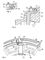
- Fig. 1 shows a section through a guide in the intake of a compressor.
- Such compressors are, as described above, used in exhaust gas turbochargers to increase the performance of internal combustion engines.
- the arrows in the figure indicate the flow path of the medium to be compressed, which is usually air or optionally an air-fuel mixture for the combustion process in the internal combustion engine.
- guide devices can be used in any type of compressor, for example, in electric motors driven industrial compressors.
- the guide device comprises a plurality of guide vanes 10 arranged aligned with respect to the compressor axis in the radial direction.
- each of the guide vanes comprises a blade shank 12 with which the blade profile is rotatably mounted in a housing.
- the blade profile can be rotated about the axis of the blade shank.
- an adjusting ring 30 is provided, which is arranged concentrically to the axis of the compressor. By turning the adjusting ring 30, all blades are simultaneously adjusted about the respective axes of their shovel shafts.
- the ball head 14 is guided in a groove 31 of the adjusting ring with two mutually parallel walls. In the groove of the ball head has the translational and rotational freedom of movement, which are necessary to implement the torque transfer.
- the ball socket is at least partially made of a translationally displaceable sliding shoe 20th educated. If the adjusting ring 30 is rotated for adjusting the guide vanes, then the sliding shoe 20 is displaced by the ball head 14 in the groove 31 in the plane of the groove walls. If the adjusting ring is turned away, the position of the adjusting lever changes relative to the adjusting ring.
- the translational displacement of the center of rotation of the ball head is made possible by sliding the sliding wall along the groove walls, while for the rotation of the ball head in the ball socket formed by the sliding shoe can rotate arbitrarily in any direction.
- the shoe may also be formed in two parts by a ball socket half is arranged with a flat, sliding back on each side of the groove in the adjusting ring.
- the torque is transmitted from the adjusting ring 30 to the blade shank 12 via a cylindrical pin 15 arranged at the free end of the adjusting lever 13.
- the pin engages in a bore of a cylindrical sliding element 21 likewise mounted in a bore 32 in the adjusting ring 30.
- the sliding cylinder 21 can be rotated in the bore 32 about its own axis and move along its own axis.
- the bore in the sliding cylinder, which is provided for receiving the pin 15, is perpendicular to the axis of the sliding cylinder.
- the pin can be rotated in this hole around its own axis and move along its own axis.
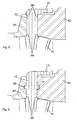
- the pin 15 as in the Fig. 9 shown, fixed in the sliding cylinder 21 and be slidably mounted in a corresponding hole in the free end of the adjusting lever 13 of the guide vane.
- the blade profile 11, blade shank 12 and the adjusting lever 13, together with the attachment required for torque transmission, that is to say the ball head 14 or the pin 15, are integrally formed.
- the entire guide blade 10 with its functional components cast or milled from one piece or force of several parts prior to installation in the housing force, shape or materially joined together in one piece.
- the blade profile, the blade shank and the adjusting lever is poured as a piece and then driven the ball head or pin into a designated opening in the adjusting lever with interference fit or loosely inserted and welded or -gegossen.
- the housing is divided according to the invention in the region of the bearing points of the guide vanes.
- Fig. 2 how out Fig. 2 can be seen, at least two, with respect to the compressor axis joinable in the axial direction housing parts 41 and 42 are provided. In the region of the bearing point of each guide vanes, the two housing parts together form the recess 45. The two housing parts 41 and 42 are held together, for example, with connecting elements in holes 46 provided for this purpose or via other subsequently installed housing parts.
- the storage of the guide vanes and the adjusting ring can be greatly simplified.
- the blade shank in the axial direction instead of an additional bearing bush or with outboard bearing points in a simple manner to radially projecting housing edges 49 secure.
- These housing protrusions 49 may be provided on both sides or on a housing part in each case at the axial ends of the bearing point of the blade shank.
- an at least partially circumferential groove in the recess between the two housing parts 41 and 42 a the blade shank also at least partially circumferential projection 17 record.
- the groove may also be embedded in the blade shank and the housing parts may be provided with a corresponding projection.
- a groove is embedded in a housing part while the other housing part has a projection and is provided according to the blade shank with a projection and a groove.
- grooves are recessed both in the blade shank and in the surrounding housing. An arranged in the grooves bearing ring provides in this Variant for the axial bearing of the guide vanes. All these variants of the internal thrust bearings allow a reduction in the axial clearance of the vanes.
- the bearing components, so the housing parts and / or the blade shank can be hardened or provided with a coating of an abrasion-resistant material.
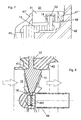
- the axial and radial bearing of the adjusting ring can be, as in Fig. 7 shown, also realized in a simple manner.
- the adjusting ring 30 is arranged together with the guide vanes between the housing parts or on one of the two housing parts.
- the final alignment of the adjusting ring in the axial direction then takes place automatically.
- the adjusting ring 30 is supported from both sides by a corresponding bearing element 47 'and 47 "in the axial direction Fig. 2
- the first axial bearing element 47 ' is part of the first housing part 41
- the second axial bearing element 47 is part of the second housing part 42.
- the radial bearing of the adjusting ring can be achieved in a simple manner by supporting the adjusting ring on a circumferential projection 48.
- the bearing parts of the adjusting ring can be hardened or coated.
- a central housing body is optionally arranged according to an embodiment of the inventive guide device.
- This central body is concentric with the axis of the compressor.
- the central body is part of the housing which forms the flow channel of the medium to be compressed in the region of the guide device.
- the central body 44 may be positioned and held by one or more radially extending housing ribs 43.
- the central body can also be positioned and held on the vane tips.
- radially guided holes 441 are shown in the central body 44, in which specially designed shafts 16 engage the blade tips.
- This device with the rays around the Central body arranged vanes also allows a simplified assembly of the vanes, which can already be arranged around the central body 44 prior to introduction into one of the two housing parts 41 or 42. Subsequently, the unit of central body and all vanes can be performed in a single step to the designated space.
- corresponding bores may also be provided in the embodiment with a central body positioned and held by means of a retaining rib.
- they also serve a simplified assembly by the guide vanes are inserted with the special blade tip shafts in the holes in the central body, before they are then placed in the radially extending recesses in the one housing part.
- the described blade tip shanks can be fixedly connected to the tips of the guide vanes, or rotatably mounted in holes provided in the blade tips.
- the shafts may also be fixedly connected to the central body, so that during mounting the guide vanes are plugged with their holes at the blade tips on the shafts.
Claims (13)
- Dispositif directeur à pré-tourbillonnement pour produire un pré-tourbillonnement dans la zone d'aspiration d'un compresseur, avec des aubes directrices (10), qui peuvent pivoter respectivement autour d'un axe d'aube (12) relié à l'aube directrice, avec une bague de réglage pivotante (30), et avec des leviers de réglage (13) pour transmettre un couple de rotation de la bague de réglage (30) à l'axe d'aube (12) de chaque aube directrice, caractérisé en ce que l'axe d'aube (12) et le levier de réglage (13) des aubes directrices sont chaque fois réalisés en une seule pièce.
- Dispositif directeur à pré-tourbillonnement selon la revendication 1, caractérisé en ce que le levier de réglage de chaque aube directrice comprend une tige cylindrique (15), qui est apte à tourner autour de son axe et à se déplacer le long de son axe en étant guidée dans un alésage d'un élément de transmission cylindrique (21), dans lequel l'élément de transmission (21) est apte à tourner autour de son axe et à se déplacer le long de son axe en étant guidé dans un alésage (32) de la bague de réglage (30).
- Dispositif directeur à pré-tourbillonnement selon la revendication 1, caractérisé en ce que le levier de réglage (13) de chaque aube directrice comporte un alésage, dans lequel une tige (15) saillante radialement sur un élément de transmission cylindrique est guidée, dans lequel l'élément de transmission (21) est apte à tourner autour de son axe et à se déplacer le long de son axe en étant guidé dans un alésage (32) de la bague de réglage (30).
- Dispositif directeur à pré-tourbillonnement selon la revendication 1, caractérisé en ce que le levier de réglage de chaque aube directrice présente une extrémité réalisée à la manière d'une tête sphérique (14), qui est guidée dans une rainure (31) de la bague de réglage (30), dans lequel la rainure (31) présente des parois orientées parallèlement l'une à l'autre, entre lesquelles la tête sphérique (14) du levier de réglage est guidée.
- Dispositif directeur à pré-tourbillonnement selon la revendication 4, caractérisé en ce que la tête sphérique (14) est guidée de façon rotative dans une cuvette sphérique d'un élément de transmission (20), et en ce que l'élément de transmission (20) est apte à se déplacer le long des parois orientées parallèlement l'une à l'autre.
- Dispositif directeur à pré-tourbillonnement selon l'une quelconque des revendications 1 à 5, caractérisé en ce qu'un boîtier, dans lequel les aubes directrices (10) sont montées de façon rotative, se compose d'au moins deux parties (41, 42) réunies dans la région des paliers de l'aube directrice.
- Dispositif directeur à pré-tourbillonnement selon l'une quelconque des revendications 1 à 6, caractérisé en ce que des saillies (49) s'étendant radialement par rapport à l'axe de rotation des aubes directrices sont disposées sur l'axe d'aube (12) et sur le boîtier (41, 42) entourant l'axe d'aube, dans lequel une saillie de l'axe d'aube et une saillie du boîtier s'engagent respectivement l'une dans l'autre pour l'appui axial de l'aube directrice.
- Dispositif directeur à pré-tourbillonnement selon l'une quelconque des revendications 1 à 7, caractérisé en ce qu'une rainure orientée radialement par rapport à l'axe de rotation de l'aube directrice est pratiquée dans l'axe d'aube (12) et/ou dans le boîtier (41, 42) entourant l'axe d'aube, rainure qui coopère avec une saillie (17) s'engageant dans la rainure et s'étendant radialement par rapport à l'axe de rotation de l'aube directrice et/ou avec une bague d'appui, pour l'appui axial de l'aube directrice.
- Dispositif directeur à pré-tourbillonnement selon l'une quelconque des revendications 1 à 8, caractérisé en ce qu'un corps central (44) est disposé dans la région des pointes des aubes directrices disposées en forme de rayons autour d'un axe.
- Dispositif directeur à pré-tourbillonnement selon la revendication 9, caractérisé en ce que le corps central (44) est fixé sur une partie de boîtier située à l'extérieur (41) au moyen d'au moins une nervure de retenue (43) guidée radialement vers l'extérieur.
- Dispositif directeur à pré-tourbillonnement selon l'une quelconque des revendications 9 ou 10, caractérisé en ce que des pivots (16) formés sur les pointes d'aube sont montés de façon rotative dans des alésages (441) orientés radialement du corps central (44).
- Compresseur, comprenant un dispositif directeur à pré-tourbillonnement selon l'une quelconque des revendications précédentes.
- Turbocompresseur à gaz d'échappement, comprenant un compresseur comportant un dispositif directeur à pré-tourbillonnement selon l'une quelconque des revendications précédentes.
Priority Applications (1)
| Application Number | Priority Date | Filing Date | Title |
|---|---|---|---|
| EP07701890A EP2002127B1 (fr) | 2006-03-31 | 2007-02-22 | Dispositif directeur à pré-tourbillonnement |
Applications Claiming Priority (3)
| Application Number | Priority Date | Filing Date | Title |
|---|---|---|---|
| EP06405137A EP1840386A1 (fr) | 2006-03-31 | 2006-03-31 | Dispositif de prérotation |
| EP07701890A EP2002127B1 (fr) | 2006-03-31 | 2007-02-22 | Dispositif directeur à pré-tourbillonnement |
| PCT/CH2007/000090 WO2007112601A1 (fr) | 2006-03-31 | 2007-02-22 | Dispositif directeur à pré-tourbillonnement |
Publications (2)
| Publication Number | Publication Date |
|---|---|
| EP2002127A1 EP2002127A1 (fr) | 2008-12-17 |
| EP2002127B1 true EP2002127B1 (fr) | 2009-11-25 |
Family
ID=36926401
Family Applications (2)
| Application Number | Title | Priority Date | Filing Date |
|---|---|---|---|
| EP06405137A Withdrawn EP1840386A1 (fr) | 2006-03-31 | 2006-03-31 | Dispositif de prérotation |
| EP07701890A Expired - Fee Related EP2002127B1 (fr) | 2006-03-31 | 2007-02-22 | Dispositif directeur à pré-tourbillonnement |
Family Applications Before (1)
| Application Number | Title | Priority Date | Filing Date |
|---|---|---|---|
| EP06405137A Withdrawn EP1840386A1 (fr) | 2006-03-31 | 2006-03-31 | Dispositif de prérotation |
Country Status (7)
| Country | Link |
|---|---|
| US (1) | US20070231125A1 (fr) |
| EP (2) | EP1840386A1 (fr) |
| JP (1) | JP2009531581A (fr) |
| KR (1) | KR20080106955A (fr) |
| CN (1) | CN101415951A (fr) |
| DE (1) | DE502007002109D1 (fr) |
| WO (1) | WO2007112601A1 (fr) |
Families Citing this family (17)
| Publication number | Priority date | Publication date | Assignee | Title |
|---|---|---|---|---|
| DE102009008531A1 (de) * | 2009-02-11 | 2010-08-12 | Bosch Mahle Turbo Systems Gmbh & Co. Kg | Verstellring für eine Ladeeinrichtung, insbesondere für einen Abgasturbolader eines Kraftfahrzeugs |
| US9200640B2 (en) | 2009-11-03 | 2015-12-01 | Ingersoll-Rand Company | Inlet guide vane for a compressor |
| ITBS20100021A1 (it) * | 2010-02-08 | 2011-08-09 | Ind Saleri Italo Spa | Pompa di raffreddamento con gruppo valvola |
| JP5440277B2 (ja) * | 2010-03-09 | 2014-03-12 | 株式会社Ihi | 過給機付エンジンのブローバイガス処理装置 |
| JP5935249B2 (ja) * | 2011-07-07 | 2016-06-15 | 株式会社Ihi | 可変ガイドベーンの軸受装置及び過給機 |
| JP5747703B2 (ja) * | 2011-07-13 | 2015-07-15 | 株式会社Ihi | ターボ圧縮機 |
| US10107296B2 (en) * | 2013-06-25 | 2018-10-23 | Ford Global Technologies, Llc | Turbocharger systems and method to prevent compressor choke |
| CN103438015B (zh) * | 2013-08-05 | 2016-07-06 | 苏州欧拉工程技术有限公司 | 一种高效节能的双吸风机 |
| CN103423198B (zh) * | 2013-08-05 | 2016-03-02 | 苏州欧拉工程技术有限公司 | 一种进气预旋器 |
| TWI614410B (zh) * | 2013-12-17 | 2018-02-11 | 財團法人工業技術研究院 | 進氣導葉組件 |
| US10240480B2 (en) * | 2014-11-21 | 2019-03-26 | Borgwarner Inc. | Variable turbine geometry vane with single-axle, self-centering pivot feature |
| US20170152860A1 (en) * | 2015-11-30 | 2017-06-01 | Borgwarner Inc. | Compressor inlet guide vanes |
| US20180058247A1 (en) * | 2016-08-23 | 2018-03-01 | Borgwarner Inc. | Vane actuator and method of making and using the same |
| CN106224013B (zh) * | 2016-08-29 | 2018-08-10 | 萍乡德博科技股份有限公司 | 一种用于涡轮增压器的喷嘴环 |
| DE102017216332A1 (de) * | 2017-09-14 | 2019-03-14 | Continental Automotive Gmbh | Verdichter für eine Aufladevorrichtung einer Brennkraftmaschine und Aufladevorrichtung für eine Brennkraftmaschine |
| CN107989829B (zh) * | 2017-12-10 | 2020-10-30 | 徐州新南湖科技有限公司 | 一种矿用风机保护罩 |
| KR20210124588A (ko) * | 2020-04-06 | 2021-10-15 | 현대자동차주식회사 | 연속 가변 트림 컴프레서 |
Family Cites Families (10)
| Publication number | Priority date | Publication date | Assignee | Title |
|---|---|---|---|---|
| US2606713A (en) * | 1948-04-26 | 1952-08-12 | Snecma | Adjustable inlet device for compressors |
| BE794140A (fr) * | 1972-01-26 | 1973-05-16 | Demag Ag | Distributeur pour turbocompresseur |
| US4428714A (en) * | 1981-08-18 | 1984-01-31 | A/S Kongsberg Vapenfabrikk | Pre-swirl inlet guide vanes for compressor |
| US4726744A (en) * | 1985-10-24 | 1988-02-23 | Household Manufacturing, Inc. | Tubocharger with variable vane |
| DE3711224A1 (de) * | 1987-04-03 | 1988-10-13 | Gutehoffnungshuette Man | Verstelleinrichtung fuer die leitschaufeln einer axialstroemungsmaschine |
| GB8722714D0 (en) * | 1987-09-26 | 1987-11-04 | Rolls Royce Plc | Variable guide vane arrangement for compressor |
| US4932206A (en) * | 1988-08-17 | 1990-06-12 | Sundstrand Corporation | Guide vane assembly for auxiliary power unit |
| US5184459A (en) * | 1990-05-29 | 1993-02-09 | The United States Of America As Represented By The Secretary Of The Air Force | Variable vane valve in a gas turbine |
| DE4237031C1 (de) * | 1992-11-03 | 1994-02-10 | Mtu Muenchen Gmbh | Verstellbare Leitschaufel |
| DE4309636C2 (de) * | 1993-03-25 | 2001-11-08 | Abb Turbo Systems Ag Baden | Radialdurchströmte Abgasturboladerturbine |
-
2006
- 2006-03-31 EP EP06405137A patent/EP1840386A1/fr not_active Withdrawn
-
2007
- 2007-02-22 WO PCT/CH2007/000090 patent/WO2007112601A1/fr active Application Filing
- 2007-02-22 EP EP07701890A patent/EP2002127B1/fr not_active Expired - Fee Related
- 2007-02-22 DE DE502007002109T patent/DE502007002109D1/de active Active
- 2007-02-22 CN CNA2007800117121A patent/CN101415951A/zh active Pending
- 2007-02-22 KR KR1020087023917A patent/KR20080106955A/ko not_active Application Discontinuation
- 2007-02-22 JP JP2009501808A patent/JP2009531581A/ja not_active Withdrawn
- 2007-03-28 US US11/727,770 patent/US20070231125A1/en not_active Abandoned
Also Published As
| Publication number | Publication date |
|---|---|
| WO2007112601A1 (fr) | 2007-10-11 |
| US20070231125A1 (en) | 2007-10-04 |
| DE502007002109D1 (de) | 2010-01-07 |
| CN101415951A (zh) | 2009-04-22 |
| JP2009531581A (ja) | 2009-09-03 |
| EP2002127A1 (fr) | 2008-12-17 |
| KR20080106955A (ko) | 2008-12-09 |
| EP1840386A1 (fr) | 2007-10-03 |
Similar Documents
| Publication | Publication Date | Title |
|---|---|---|
| EP2002127B1 (fr) | Dispositif directeur à pré-tourbillonnement | |
| EP1977084B1 (fr) | Dispositif de direction pouvant etre deplace | |
| EP1662094B1 (fr) | Distributeur pour un turbocompresseur et turbocompresseur | |
| EP2209969B1 (fr) | Dispositif de suralimentation | |
| WO2007082398A1 (fr) | Dispositif de direction pouvant être deplace | |
| EP2018480B1 (fr) | Turbocompresseur | |
| DE102010038185B4 (de) | Düseneinrichtung eines Turboladers variabler Geometrie | |
| DE102008007670B4 (de) | Steuerring für VTG | |
| WO2006060925A1 (fr) | Dispositif directeur pour turbine a gaz d'echappement | |
| EP1520959B1 (fr) | Turbocompresseur avec distributeur à géométrie variable | |
| EP2006494A1 (fr) | Engrenage pour dispositif de conduite à prérotation | |
| EP2006495A1 (fr) | Réglage de position pour dispositif de conduite à prérotation | |
| EP1998026A2 (fr) | Dispositif de chargement | |
| EP1635041B1 (fr) | Callage de superchargeur | |
| EP3176386B1 (fr) | Système de virole interne, virole interne, boîtier intermédiaire et turbomachine associés | |
| EP2510207B1 (fr) | Dispositif d'ajustage pour un dispositif de suralimentation, en particulier pour un turbocompresseur à gaz d'échappement | |
| DE102008000508A1 (de) | Abgasturbolader mit verstellbarer Turbinengeometrie | |
| DE102008020732A1 (de) | Ladeeinrichtung | |
| DE102007052735B4 (de) | Ladeeinrichtung | |
| DE102004023211A1 (de) | Abgasturbolader für eine Brennkraftmaschine mit variabler Turbinengeometrie | |
| DE102011080995A1 (de) | Turbine mit variabler Geometrie und deren Montage | |
| EP1574673A1 (fr) | Aubes de guidage variables et turbosoufflante avec ces aubes | |
| DE102004023282A1 (de) | Abgasturbolader für eine Brennkraftmaschine mit variabler Turbinengeometrie | |
| DE102004031986A1 (de) | Abgasturbolader für eine Brennkraftmaschine | |
| EP1391585A2 (fr) | Turbocompresseur à géométrie variable |
Legal Events
| Date | Code | Title | Description |
|---|---|---|---|
| PUAI | Public reference made under article 153(3) epc to a published international application that has entered the european phase |
Free format text: ORIGINAL CODE: 0009012 |
|
| 17P | Request for examination filed |
Effective date: 20080915 |
|
| AK | Designated contracting states |
Kind code of ref document: A1 Designated state(s): CZ DE FR GB |
|
| RBV | Designated contracting states (corrected) |
Designated state(s): CZ DE FR GB |
|
| GRAP | Despatch of communication of intention to grant a patent |
Free format text: ORIGINAL CODE: EPIDOSNIGR1 |
|
| DAX | Request for extension of the european patent (deleted) | ||
| GRAS | Grant fee paid |
Free format text: ORIGINAL CODE: EPIDOSNIGR3 |
|
| GRAA | (expected) grant |
Free format text: ORIGINAL CODE: 0009210 |
|
| AK | Designated contracting states |
Kind code of ref document: B1 Designated state(s): CZ DE FR GB |
|
| REG | Reference to a national code |
Ref country code: GB Ref legal event code: FG4D Free format text: NOT ENGLISH |
|
| REF | Corresponds to: |
Ref document number: 502007002109 Country of ref document: DE Date of ref document: 20100107 Kind code of ref document: P |
|
| PLBE | No opposition filed within time limit |
Free format text: ORIGINAL CODE: 0009261 |
|
| STAA | Information on the status of an ep patent application or granted ep patent |
Free format text: STATUS: NO OPPOSITION FILED WITHIN TIME LIMIT |
|
| 26N | No opposition filed |
Effective date: 20100826 |
|
| PGFP | Annual fee paid to national office [announced via postgrant information from national office to epo] |
Ref country code: CZ Payment date: 20110218 Year of fee payment: 5 |
|
| PGFP | Annual fee paid to national office [announced via postgrant information from national office to epo] |
Ref country code: FR Payment date: 20120227 Year of fee payment: 6 |
|
| PGFP | Annual fee paid to national office [announced via postgrant information from national office to epo] |
Ref country code: DE Payment date: 20120221 Year of fee payment: 6 |
|
| PGFP | Annual fee paid to national office [announced via postgrant information from national office to epo] |
Ref country code: GB Payment date: 20120221 Year of fee payment: 6 |
|
| GBPC | Gb: european patent ceased through non-payment of renewal fee |
Effective date: 20130222 |
|
| PG25 | Lapsed in a contracting state [announced via postgrant information from national office to epo] |
Ref country code: CZ Free format text: LAPSE BECAUSE OF NON-PAYMENT OF DUE FEES Effective date: 20130222 |
|
| REG | Reference to a national code |
Ref country code: FR Ref legal event code: ST Effective date: 20131031 |
|
| REG | Reference to a national code |
Ref country code: DE Ref legal event code: R119 Ref document number: 502007002109 Country of ref document: DE Effective date: 20130903 |
|
| PG25 | Lapsed in a contracting state [announced via postgrant information from national office to epo] |
Ref country code: FR Free format text: LAPSE BECAUSE OF NON-PAYMENT OF DUE FEES Effective date: 20130228 Ref country code: GB Free format text: LAPSE BECAUSE OF NON-PAYMENT OF DUE FEES Effective date: 20130222 Ref country code: DE Free format text: LAPSE BECAUSE OF NON-PAYMENT OF DUE FEES Effective date: 20130903 |