EP1661683B1 - Procédé et dispositif de moulage par compression de matière plastique - Google Patents
Procédé et dispositif de moulage par compression de matière plastique Download PDFInfo
- Publication number
- EP1661683B1 EP1661683B1 EP06000562A EP06000562A EP1661683B1 EP 1661683 B1 EP1661683 B1 EP 1661683B1 EP 06000562 A EP06000562 A EP 06000562A EP 06000562 A EP06000562 A EP 06000562A EP 1661683 B1 EP1661683 B1 EP 1661683B1
- Authority
- EP
- European Patent Office
- Prior art keywords
- holder
- compression moulding
- elements
- compression molding
- pellet
- Prior art date
- Legal status (The legal status is an assumption and is not a legal conclusion. Google has not performed a legal analysis and makes no representation as to the accuracy of the status listed.)
- Expired - Lifetime
Links
Images

Classifications
-
- B—PERFORMING OPERATIONS; TRANSPORTING
- B29—WORKING OF PLASTICS; WORKING OF SUBSTANCES IN A PLASTIC STATE IN GENERAL
- B29C—SHAPING OR JOINING OF PLASTICS; SHAPING OF MATERIAL IN A PLASTIC STATE, NOT OTHERWISE PROVIDED FOR; AFTER-TREATMENT OF THE SHAPED PRODUCTS, e.g. REPAIRING
- B29C43/00—Compression moulding, i.e. applying external pressure to flow the moulding material; Apparatus therefor
- B29C43/32—Component parts, details or accessories; Auxiliary operations
- B29C43/34—Feeding the material to the mould or the compression means
-
- B—PERFORMING OPERATIONS; TRANSPORTING
- B29—WORKING OF PLASTICS; WORKING OF SUBSTANCES IN A PLASTIC STATE IN GENERAL
- B29C—SHAPING OR JOINING OF PLASTICS; SHAPING OF MATERIAL IN A PLASTIC STATE, NOT OTHERWISE PROVIDED FOR; AFTER-TREATMENT OF THE SHAPED PRODUCTS, e.g. REPAIRING
- B29C43/00—Compression moulding, i.e. applying external pressure to flow the moulding material; Apparatus therefor
- B29C43/32—Component parts, details or accessories; Auxiliary operations
- B29C43/52—Heating or cooling
-
- B—PERFORMING OPERATIONS; TRANSPORTING
- B29—WORKING OF PLASTICS; WORKING OF SUBSTANCES IN A PLASTIC STATE IN GENERAL
- B29C—SHAPING OR JOINING OF PLASTICS; SHAPING OF MATERIAL IN A PLASTIC STATE, NOT OTHERWISE PROVIDED FOR; AFTER-TREATMENT OF THE SHAPED PRODUCTS, e.g. REPAIRING
- B29C43/00—Compression moulding, i.e. applying external pressure to flow the moulding material; Apparatus therefor
- B29C43/32—Component parts, details or accessories; Auxiliary operations
- B29C43/34—Feeding the material to the mould or the compression means
- B29C2043/3405—Feeding the material to the mould or the compression means using carrying means
- B29C2043/3411—Feeding the material to the mould or the compression means using carrying means mounted onto arms, e.g. grippers, fingers, clamping frame, suction means
-
- B—PERFORMING OPERATIONS; TRANSPORTING
- B29—WORKING OF PLASTICS; WORKING OF SUBSTANCES IN A PLASTIC STATE IN GENERAL
- B29C—SHAPING OR JOINING OF PLASTICS; SHAPING OF MATERIAL IN A PLASTIC STATE, NOT OTHERWISE PROVIDED FOR; AFTER-TREATMENT OF THE SHAPED PRODUCTS, e.g. REPAIRING
- B29C43/00—Compression moulding, i.e. applying external pressure to flow the moulding material; Apparatus therefor
- B29C43/32—Component parts, details or accessories; Auxiliary operations
- B29C43/50—Removing moulded articles
- B29C2043/503—Removing moulded articles using ejector pins, rods
-
- B—PERFORMING OPERATIONS; TRANSPORTING
- B29—WORKING OF PLASTICS; WORKING OF SUBSTANCES IN A PLASTIC STATE IN GENERAL
- B29C—SHAPING OR JOINING OF PLASTICS; SHAPING OF MATERIAL IN A PLASTIC STATE, NOT OTHERWISE PROVIDED FOR; AFTER-TREATMENT OF THE SHAPED PRODUCTS, e.g. REPAIRING
- B29C31/00—Handling, e.g. feeding of the material to be shaped, storage of plastics material before moulding; Automation, i.e. automated handling lines in plastics processing plants, e.g. using manipulators or robots
- B29C31/04—Feeding of the material to be moulded, e.g. into a mould cavity
- B29C31/042—Feeding of the material to be moulded, e.g. into a mould cavity using dispensing heads, e.g. extruders, placed over or apart from the moulds
- B29C31/048—Feeding of the material to be moulded, e.g. into a mould cavity using dispensing heads, e.g. extruders, placed over or apart from the moulds the material being severed at the dispensing head exit, e.g. as ring, drop or gob, and transported immediately into the mould, e.g. by gravity
Definitions
- the invention relates to a method for molding thermoplastic between two compression molding elements and a device thereto.
- Compression molding is a long-known means, in particular to produce articles made of a thermoplastic material.
- closures are made for food packaging, especially plastic closures for beverage bottles.
- the raw granules are extruded and the desired amount is cut off, which is deposited on a part of a compression molding tool. Subsequently, a second molding tool penetrates into the first molding tool so that the desired product is molded.
- thermoplastic material is dispensed as an annular blank in an extruder.
- a molding die is arranged, the inner shape of which corresponds to the outer shape of the tube head to be produced.
- the intermediate carrier has a coaxially extendable rod, which protrudes beyond the surface and on the one hand centered the blank with an annular cross-section and on the other hand keeps the discharge opening for the tube head during pressing free.
- the EP 0 728 064 B shows a method for molding a tube made of plastic tube to a tube tube.
- the lenticular blank is deposited on the auxiliary carrier.
- a mold pin is arranged centrally on the subcarrier and displaceable in the auxiliary carrier and in the subcarrier bar during the molding process against axial spring pressure.
- the mold comprises a forming part which is formed by a part of the end surface of the subcarrier, the inner contour, the mold jaws and the shoulder mold space.
- a recess in a serving for the guidance of the subcarrier with the subcarrier rod Insert is designed such that the subcarrier can be accommodated in the lowest position and then the end face forms the mold bottom.
- the US 3,795,473 (FA Automation System Design & Construction) describes a machine for the production of brake shoes and brake linings. This includes a plurality of hot presses on a first turntable and additional assemblies for feeding preformed pellets to the hot presses. On a second turntable, a press for producing the pellets and adjacent thereto a brake pad composition metering device may be arranged. The pellets produced are transported by means of a pivoting pliers from the second turntable to the hot presses on the first turntable.
- the hot presses comprise a master cylinder, a pilot cylinder and a plurality of heating plates and mold elements. After inserting a pellet, the corresponding press with the turntable is rotated by one position, so that the next press is positioned at the transfer point.
- the US 5,863,571 (Sidel) concerns a machine for the production of containers, such as As bottles or pots, by heat treatment and blow molding of plastic preforms.
- the machine comprises at least two forming tools arranged on a turntable.
- Each mold comprises at least two cavities and thus enables the production of twice the number of small containers on a machine designed for the production of larger containers.
- devices for adjusting the cadence are provided in the following.
- To feed the preforms in the cavities of the molds serve transfer elements, which comprise an arm with a holding device with clamps. The arm is rotatable about a pivot axis.
- Corresponding devices are also provided for removing the blow-molded container by a further device.
- the object of the invention is to provide a method and a structurally simple device, which allow the production of closures, in particular of an extruded plastic raw material without an uncontrolled surface structure occurs at the closures.
- a portion of raw material is deposited on a holder with a small contact surface.
- the raw mass on the bearing surface has a distance from a molding press element and is delivered to the molding elements only immediately before or at the beginning of the pressing.
- the holder is pliers-shaped and arranged on a side wall of one of the compression molding elements.
- the extruded portion of the plastic - also called pellet - has a temperature of about 180 ° Celsius.
- the compression molding elements have an operating temperature which is about 120 ° to 150 ° lower.
- the portion of the extruded plastic mass is deposited on the first compression molding element, it is not completely in the inventive method on this, but only on the small contact surface of the holder.
- the "cold shock" at the contact surface to the holder is so small that the existing in the prior art effects are largely avoided. Only immediately before or at the beginning of pressing is the pellet in contact with the compression molding elements.
- the pliers parts open and the pellet falls, preferably precisely positioned on one of the compression molding elements.
- the holder is completely retracted or swung away to the side so that the other compression molding element can penetrate into the one compression molding element.
- the pincer-shaped holder protrudes from the side into the first compression molding element.
- the holder may also consist of several parts, which are arranged on the circumference of the compression molding element.
- the pellet is centered by the holder.
- the centering of the pellet is done on the one hand by an approximately accurate deposition of the pellet on the holder and on the other hand by the design of the support surface of the holder.
- a uniform distribution of mass usually affects the quality of production. In asymmetric molds, the centering is obsolete, unless a specific (centric or eccentric) position is desired.
- the device according to the invention comprises a first compression molding element with a holder and a second compression molding element which penetrates into the first compression molding element in such a way that a pellet - a portion of extruded, thermoplastic plastic material - is compression molded between these two compression molding elements.
- the holder has a small bearing surface for the pellet and supports it before it comes into contact with the first compression molding.
- the bearing surface must be designed accordingly. If the pellet has a consistency which hardly allows the pellet to flow, the support surface can be made smaller than if the pellet tends to flow.
- a timed moving of the holder is preferred.
- Such control is tuned to the power stroke of the entire manufacturing device.
- the holder lowers as soon as the second compression molding element penetrates into the first compression molding element.
- the known systems offer.
- the control of the holder is cam-controlled, the holder is reciprocated by a mechanism which extends along a preferably curved rail or along a predetermined curved path.
- the second compression molding element is preferably also cam-controlled in such a case.
- the two controllers can also be combined into one controller. For entertaining reasons, however, two coordinated but mechanically largely independent controls for the holder and the compression molding elements are preferred.
- the holder can for example also be pressure-controlled.
- a sensor measures the pressure on the holder. As soon as the second molding element touches the pellet and thus the pressure on the holder increases, it is withdrawn and releases the pellet for the molding process.
- the control can also be pneumatic or hydraulic.
- the device and thus the compression molding elements are in particular designed for molding plastic closures, as they are used for beverage bottles.
- the first compression molding element is preferably arranged at the bottom, serves as a so-called die and receives the holder.
- the second compression molding element is designed as a punch and penetrates into the first compression molding element.
- a so-called turret is used for the production of molded products, which has a controlled rotating working platform, which is equipped with a plurality of inventive devices.
- Each of the arranged devices has its own control, which are matched to the controls of the other devices. This allows high processing speeds and high precision.
- the control of the individual parts, in particular of the holder, the landfill device and the second compression molding elements is preferably timed.
- the control is essentially cam-controlled, which leads to an optimal movement sequence of the production. Under cam controlled is a time-controlled motion, which is controlled by a predetermined curve.
- the individual movements can be controlled with a shared curve.
- each individual movement sequence is controlled by separate curves, which are coordinated with one another.
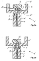
- FIG. 1 is a schematic, perspective sectional view of a compression molding member shown with a holder.
- the holder is not according to the invention, but the illustrated device and the following description are helpful in understanding the invention.
- the first molding tool 1 is arranged at the bottom, for which reason the second molding tool 14 penetrates from above into the first molding tool 1.
- the names above and below refer to the drawing shown.
- the first molding tool 1 could also be arranged at the top, which would require penetration of the second molding tool 14 from below into the first molding tool 1.
- the first molding tool 1 consists of a die 2 and a base 3.
- the die 2 is a hollow cylinder 4 with a bottom 5.
- the die 2 is the negative mold, which the exterior design of the plastic closure 16 determined.
- the thickness of the bottom 5 of the die 2 is approximately equal to the thickness of the hollow cylinder 4 is formed.
- the base 3 is monolithically connected to the die 2. In the illustrated device, the base 3 is formed as a cylinder. The dimensions depend on the product to be manufactured and the associated loads.
- a bore is arranged in the axial direction, in which a plunger 6 in the vertical direction (see arrow 11) can be moved back and forth.
- a sliding layer is provided, for example, a Teflon coating to substantially eliminate the friction of the plunger 6 with the base 3.
- a recess 7 is arranged in the imaginary dividing line between the lower edge of the bottom 5 and the upper edge of the base 3.
- the holder 8 consists on the one hand of a base plate 9 and three pins 10 which are fixed to the base plate 9.
- the base plate 9 is connected to the plunger 6 such that reciprocating movements of the plunger 6 are simulated simultaneously by the base plate 9.
- the bottom 5 has according to the thickness and the number of pins 10 holes formed so that the pins 10 can penetrate the bottom 5.
- the arrangement of the pins 10 as a "tripod" is exemplary, depending on the application, the number may range from one to a number of pins required according to the application.
- the holder is pulled back in the vertical direction or in this illustration. Since the recess 7 has to accommodate the holder 8 to a large extent, the height of the recess 7 is exactly or slightly more than the thickness of the base plate 9 and the length of the pins 10 minus the thickness of the bottom 5. Further details will become apparent in the following embodiment Part of the individual process steps.
- FIGS. 2a-c show individual steps of a method for molding thermoplastic by means of schematic sections.
- the holder used is not according to the invention, but the following description of the method is helpful in understanding the invention.
- FIG. 2a shows the starting position of the first compression molding tool 1, in which the holder 8 is raised to the stop of the base plate 9.
- the first molding tool 1 is cooled down to about 17 ° Celsius with a water cycle (not shown here).
- the pins 10 of the holder 8 penetrate the holes in the bottom 5 and project beyond it so far that a sufficiently large distance from the support points of the holder 8 to the bottom 5 of the compression molding element 1 is present. This ensures that the portion of extruded thermoplastic material deposited on this holder 8, referred to hereinafter as the pellet 12, does not cool down too much.
- This, although between the pellet 12 and the first molding tool 1 is a large temperature difference - in this example, about 160 ° Celsius.
- the preparation of the plastic is carried out by a known per se extrusion. As soon as a holder 8 is located under an extruder opening, a pellet 12 is cut off at this, in the working range of the turret reaching into the extruder and deposited on the pins 10 of the holder 8, or deposited. Each opening of the extruder is controlled to open and close. The process from landfill to actual compression takes about two seconds. Since the pellet 12 has only a small contact area with the substantially colder holder 8 and the residence time of the pellet 12 on this relatively short, there is no strong cooling of the pellet 12 and its temperature, which is about 180 ° C, remains until largely preserved for the actual compression molding.
- the compression molding takes place, as in Figure 2c is shown.
- the time during which the pellet is on Thus, for example, it is only 1/5 or less of the time that the pellet is from landfill to effective (described below) compression within the mold.
- the second molding tool 14 which was preheated with a water cycle (not shown here) to a temperature of about 50 ° Celsius, penetrates into the first, cooled molding tool 1.
- the punch 15 of the second compression molding tool 14 forms the inner shape, which should have, for example, the plastic closure 16.
- the temperature data is an embodiment of the preparation.
- the temperatures, in particular of the compression molding tools 1 and 14, can be adapted to the requirements and workflow without this leading to a solution which is outside the scope of the invention.
- the two compression molding tools 1 and 14 remain in the molding position for one to two seconds and cool the molded plastic closure 16. Subsequently, the first molding tool 1 is lowered and preferably pulled the second molding tool upwards. The plastic closure 16 remains adhering to the punch 15 of the second compression molding tool 14. With a sleeve (not shown here), which slides down along the punch 15, the plastic closure 16 is stripped off.
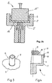
- FIG. 3 A not according to the invention variant of the holder 8 is in FIG. 3 shown.
- a tube 17 is arranged.
- the pellet is deposited on the tube 17 and this is withdrawn according to the previous versions, or sunk in the first compression molding tool.
- the tube wall of the tube 17 is preferably made as thin as possible so that the contact area between the tube 17 and the pellet is kept as small as possible. The rest of the construction of the holder 8 largely corresponds to the previously made statements.
- Fig. 4 shows a schematic representation of a laterally mounted inventive holder 18.
- the holder 18 is rotatably attached, for example, with a bolt 20.
- the holder 18 is preferably formed in two parts in the horizontal plane.
- the holder 18 can open as scissors or forceps and release the pellet 12 in a simple way for the compression molding process. So that the holder 18 is not in the way during the molding process, it is turned off, for example, about the axis of rotation 21, which is formed by the bolt 20 to the side.
- the holder 18 is swung back again.
- the construction may also be modified in that the holder 18 is drawn to the right from the action area of the second molding tool with respect to this illustration.
- the first molding tool with the holder can also be arranged at the top, based on the illustration.
- the pellet must adhere to the holder until the second molding tool is in the position that the pellet can not fall next to this second molding tool.
- the holder is designed in the form of a small pliers.
- the pins may have at their reaching into the molding tool end bends, which hold the pellet temporarily, similar to a gripping device.
- the retainer retracts into the first molding die and releases the pellet when it can no longer fall adjacent to the second molding tool.
- the temperatures of, for example, the holder and / or preferably of the molding tools can be adjusted.
- the flow temperatures of the water circuits, which heat the molding tools, or cool are adjusted. This makes it possible to lower the temperature difference between the pellet and the holder or, in particular, the first molding tool, so that the possibility of a "glazing" effect on the finished product is further reduced.
- plastic closures are created by the inventive method and the inventive device, which have no or only a small uncontrolled surface structure, without the production of such plastic closures is slowed down.
Claims (13)
- Procédé de formage de plastique thermoplastique entre un premier (1) et un deuxième élément de presse de formage (14), une portion (12) de masse brute étant déposée sur un support (18) de faible surface d'appui à distance d'un élément de presse de formage (1), et étant d'abord transféré directement, avant ou au début du pressage, aux éléments de presse de formage (1, respectivement 14), caractérisé en ce que le support (18) est réalisé en forme de pince et est disposé sur une paroi latérale de l'un des éléments de presse de formage (1, respectivement 14).
- Procédé selon la revendication 1, caractérisé en ce que le support (18) est ouvert en forme de cisaille ou de pince pour libérer la portion.
- Procédé selon la revendication 1 ou 2, caractérisé en ce que le support (18), après la libération de la portion, est tourné vers le côté autour d'un axe de rotation (21) et est à nouveau pivoté vers l'arrière à la fin du pressage.
- Procédé selon l'une quelconque des revendications 1 à 3, caractérisé en ce que la portion (12) est centrée par le support (18).
- Procédé selon l'une quelconque des revendications 1 à 4, caractérisé en ce que le support (18) est déplacé de manière commandée.
- Dispositif de formage de plastique thermoplastique comprenant un premier (1) et un deuxième élément de presse de formage (14), entre lesquels une portion (12) de plastique thermoplastique est pressée, comprenant un support (18) de faible surface d'appui pour le support temporaire de la portion (12) avant le contact avec les éléments de presse de formage (1 et 14), caractérisé en ce que le support (18) est réalisé en forme de pince et est disposé sur une paroi latérale de l'un des éléments de presse de formage (1, respectivement 14).
- Dispositif selon la revendication 6, caractérisé en ce que le support (18) peut être ouvert en forme de cisaille ou de pince pour libérer la portion.
- Dispositif selon la revendication 6 ou 7, caractérisé en ce que le support (18) est fixé latéralement à l'un des éléments de presse de formage sur une fixation (19).
- Dispositif selon la revendication 8, caractérisé en ce que la fixation (19) présente un axe de rotation (21) autour duquel le support (18) est fixé de manière rotative.
- Dispositif selon l'une quelconque des revendications 6 à 9, caractérisé en ce que les éléments de presse de formage (1 et 14) sont réalisés pour former des fermetures en plastique (16), l'élément de presse de formage (1) réalisé sous forme de matrice (2) étant disposé en bas et recevant le support (18).
- Dispositif selon l'une quelconque des revendications 6 à 10, caractérisé en ce que des moyens pour déplacer le support (18) de manière commandée dans le temps sont prévus.
- Tourelle rotative comprenant plusieurs dispositifs selon l'une quelconque des revendications 6 à 11.
- Tourelle rotative selon la revendication 12, caractérisée en ce que les éléments de presse de formage sont commandés par came.
Priority Applications (1)
| Application Number | Priority Date | Filing Date | Title |
|---|---|---|---|
| EP06000562A EP1661683B1 (fr) | 2001-03-19 | 2002-03-08 | Procédé et dispositif de moulage par compression de matière plastique |
Applications Claiming Priority (3)
| Application Number | Priority Date | Filing Date | Title |
|---|---|---|---|
| EP01810274A EP1243393A1 (fr) | 2001-03-19 | 2001-03-19 | Procédé de moulage par compression des matières plastiques |
| EP02701142A EP1377424B1 (fr) | 2001-03-19 | 2002-03-08 | Procede de formage de matiere thermoplastique |
| EP06000562A EP1661683B1 (fr) | 2001-03-19 | 2002-03-08 | Procédé et dispositif de moulage par compression de matière plastique |
Related Parent Applications (2)
| Application Number | Title | Priority Date | Filing Date |
|---|---|---|---|
| EP02701142.8 Division | 2002-03-08 | ||
| EP02701142A Division EP1377424B1 (fr) | 2001-03-19 | 2002-03-08 | Procede de formage de matiere thermoplastique |
Publications (2)
| Publication Number | Publication Date |
|---|---|
| EP1661683A1 EP1661683A1 (fr) | 2006-05-31 |
| EP1661683B1 true EP1661683B1 (fr) | 2011-07-13 |
Family
ID=8183799
Family Applications (3)
| Application Number | Title | Priority Date | Filing Date |
|---|---|---|---|
| EP01810274A Withdrawn EP1243393A1 (fr) | 2001-03-19 | 2001-03-19 | Procédé de moulage par compression des matières plastiques |
| EP06000562A Expired - Lifetime EP1661683B1 (fr) | 2001-03-19 | 2002-03-08 | Procédé et dispositif de moulage par compression de matière plastique |
| EP02701142A Expired - Lifetime EP1377424B1 (fr) | 2001-03-19 | 2002-03-08 | Procede de formage de matiere thermoplastique |
Family Applications Before (1)
| Application Number | Title | Priority Date | Filing Date |
|---|---|---|---|
| EP01810274A Withdrawn EP1243393A1 (fr) | 2001-03-19 | 2001-03-19 | Procédé de moulage par compression des matières plastiques |
Family Applications After (1)
| Application Number | Title | Priority Date | Filing Date |
|---|---|---|---|
| EP02701142A Expired - Lifetime EP1377424B1 (fr) | 2001-03-19 | 2002-03-08 | Procede de formage de matiere thermoplastique |
Country Status (6)
| Country | Link |
|---|---|
| US (1) | US20040130068A1 (fr) |
| EP (3) | EP1243393A1 (fr) |
| JP (1) | JP4191489B2 (fr) |
| CN (1) | CN1281397C (fr) |
| DE (1) | DE50205872D1 (fr) |
| WO (1) | WO2002074514A1 (fr) |
Families Citing this family (4)
| Publication number | Priority date | Publication date | Assignee | Title |
|---|---|---|---|---|
| ITMO20030289A1 (it) * | 2003-10-23 | 2005-04-24 | Sacmi | Apparati, metodo e articolo. |
| JP5739438B2 (ja) * | 2009-10-23 | 2015-06-24 | フレクストロニクス エイピー エルエルシーFlextronics Ap,Llc | 高速かつ低圧縮の熱可塑性材料の回転式成形装置及び成型方法 |
| CN104085071B (zh) * | 2014-07-10 | 2016-03-16 | 河南盛世塑业有限公司 | 一种塑料成型挤压柄 |
| IT201900023139A1 (it) | 2019-12-05 | 2021-06-05 | Sacmi | Metodo e apparato di stampaggio |
Family Cites Families (13)
| Publication number | Priority date | Publication date | Assignee | Title |
|---|---|---|---|---|
| AT321569B (de) * | 1971-07-05 | 1975-04-10 | Karl Holik Ing | Vorrichtung zur automatischen Herstellung von Scheibenbremsbelägen |
| JPS58145410A (ja) * | 1982-02-22 | 1983-08-30 | Aida Eng Ltd | 機械プレスによるプラスチツク材の成形方法 |
| JPS58173612A (ja) * | 1982-04-06 | 1983-10-12 | Japan Crown Cork Co Ltd | 回転式合成樹脂製容器蓋加圧成形装置 |
| DE3804464C1 (fr) * | 1988-02-12 | 1989-06-08 | Aisa Automation Industrielle S.A., Vouvry, Ch | |
| DE4009661C1 (fr) * | 1990-03-26 | 1991-03-07 | Aisa Automation Industrielle S.A., Vouvry, Ch | |
| JPH081698A (ja) * | 1994-06-15 | 1996-01-09 | Sumitomo Chem Co Ltd | 繊維強化熱可塑性樹脂成形体の製造方法およびそれに用いる金型 |
| CH689204A5 (de) * | 1994-09-19 | 1998-12-15 | Maegerle Karl Lizenz | Verfahren zur Befuellung einer Matrize zur Anformung eines Tubenkopfes an ein Tubenrohr. |
| FR2731176B1 (fr) * | 1995-03-02 | 1997-04-30 | Sidel Sa | Installation de fabrication de recipients par soufflage de preformes en matiere plastique |
| JPH0912734A (ja) * | 1995-06-29 | 1997-01-14 | Akebono Brake Ind Co Ltd | 摩擦材の製造方法及び母材投入治具 |
| US5866177A (en) * | 1997-05-16 | 1999-02-02 | Owens-Illinois Closure Inc. | Apparatus for compression molding plastic articles |
| JP3674385B2 (ja) * | 1999-04-02 | 2005-07-20 | 東洋製罐株式会社 | 合成樹脂供給装置 |
| IT1321322B1 (it) * | 2000-05-05 | 2004-01-08 | Sacmi | Apparecchiatura a giostra per la fabbricazione, mediante stampaggio apressione, di capsule in materiale plastico |
| ITBO20020226A1 (it) * | 2002-04-23 | 2003-10-23 | Sacmi | Apparecchiatura per lo stampaggio a pressione di articoli in materiale plastico , come capsule per la chiusura di contenitore e simili |
-
2001
- 2001-03-19 EP EP01810274A patent/EP1243393A1/fr not_active Withdrawn
-
2002
- 2002-03-08 EP EP06000562A patent/EP1661683B1/fr not_active Expired - Lifetime
- 2002-03-08 CN CN02806771.1A patent/CN1281397C/zh not_active Expired - Fee Related
- 2002-03-08 DE DE50205872T patent/DE50205872D1/de not_active Expired - Lifetime
- 2002-03-08 EP EP02701142A patent/EP1377424B1/fr not_active Expired - Lifetime
- 2002-03-08 WO PCT/CH2002/000142 patent/WO2002074514A1/fr active IP Right Grant
- 2002-03-08 JP JP2002573208A patent/JP4191489B2/ja not_active Expired - Fee Related
-
2003
- 2003-03-08 US US10/471,886 patent/US20040130068A1/en not_active Abandoned
Also Published As
| Publication number | Publication date |
|---|---|
| JP4191489B2 (ja) | 2008-12-03 |
| CN1498155A (zh) | 2004-05-19 |
| EP1243393A1 (fr) | 2002-09-25 |
| EP1377424B1 (fr) | 2006-02-22 |
| EP1377424A1 (fr) | 2004-01-07 |
| EP1661683A1 (fr) | 2006-05-31 |
| US20040130068A1 (en) | 2004-07-08 |
| WO2002074514A1 (fr) | 2002-09-26 |
| DE50205872D1 (de) | 2006-04-27 |
| CN1281397C (zh) | 2006-10-25 |
| JP2004526595A (ja) | 2004-09-02 |
Similar Documents
| Publication | Publication Date | Title |
|---|---|---|
| DE3023415C2 (fr) | ||
| DE2166733A1 (de) | Spritz- blas-formwerkzeug fuer eine kunststoff-spritzgussmaschine | |
| DE976187C (de) | Verfahren zum Herstellen von einseitig voellig geschlossenen Hohlkoerpern aus in der Waerme formbaren Kunststoffen | |
| EP0175642A2 (fr) | Procédé et installation pour la fabrication d'un objet moulé en matière plastique | |
| EP1129039B1 (fr) | Procede et dispositif pour presser une ebauche | |
| EP0034267B1 (fr) | Machine pour fabriquer des corps creux soufflés en matière plastique | |
| DE60310531T2 (de) | Vorrichtung und Verfahren zum Pressformen von Kunststoff-Behältern | |
| EP1661683B1 (fr) | Procédé et dispositif de moulage par compression de matière plastique | |
| EP2207663A2 (fr) | Dispositif de soufflage-étirage et procédé de fabrication de préformes | |
| WO2007063063A1 (fr) | Procede de post-traitement et dispositif approprie | |
| EP3016793B1 (fr) | Procédé et dispositif de réalisation d'un profil de fond optimisé sur des préformes | |
| EP0475112A2 (fr) | Appareil pour la formation du col d'une petite bouteille en verre | |
| EP3197655B1 (fr) | Procédé et dispositif pour réaliser un contour de col optimisé sur des préformes | |
| EP0787111B1 (fr) | Procede de fabrication d'articles moules en verre, par moulage par compression et dispositif specialement approprie pour la mise en oeuvre de ce procede | |
| EP0728064A1 (fr) | Procede de remplissage d'une matrice pour le formage d'une tete de tube sur un corps tubulaire | |
| DE1604461A1 (de) | Verfahren und Vorrichtung zum Freipressen von Gegenstaenden aus thermoplastischem Gut | |
| AT407725B (de) | Verfahren zur herstellung eines formkörpers aus kunststoff | |
| DE2166180B2 (de) | Verfahren und vorrichtung zum herstellen von hohlkoerpern aus thermoplastischem kunststoff | |
| DE2339018A1 (de) | Vorrichtung zum herstellen eines hohlkoerpers aus kunststoff durch aufblasen eines gespritzten vorformlings | |
| DE102010046663A1 (de) | Verfahren zum Herstellen von Glasgegenständen, sowie Vorrichtung | |
| DE2922195A1 (de) | Vorrichtung zur herstellung von kunststoffhohlkoerpern | |
| DE3002191A1 (de) | Maschine zur herstellung geblasener kunststoff-hohlkoerper | |
| DE10349837A1 (de) | Verfahren und Vorrichtung zur Herstellung von Kunststoff-Formteilen, insbesondere Ausgussteilen von Verpackungsbehältern | |
| DE3039741A1 (de) | Vorrichtung zum formen von im wesentlichen rohrfoermigen kunststoff-vorformlingen | |
| DE1704162A1 (de) | Vorrichtung zum Herstellen von Hohlkoerpern aus thermoplastischem Kunststoff |
Legal Events
| Date | Code | Title | Description |
|---|---|---|---|
| PUAI | Public reference made under article 153(3) epc to a published international application that has entered the european phase |
Free format text: ORIGINAL CODE: 0009012 |
|
| AC | Divisional application: reference to earlier application |
Ref document number: 1377424 Country of ref document: EP Kind code of ref document: P |
|
| AK | Designated contracting states |
Kind code of ref document: A1 Designated state(s): CH DE GB IT LI |
|
| RIN1 | Information on inventor provided before grant (corrected) |
Inventor name: FANKHAUSER, URS |
|
| AKX | Designation fees paid | ||
| 17P | Request for examination filed |
Effective date: 20061027 |
|
| RBV | Designated contracting states (corrected) |
Designated state(s): CH DE GB LI |
|
| RBV | Designated contracting states (corrected) |
Designated state(s): CH DE IT LI |
|
| REG | Reference to a national code |
Ref country code: DE Ref legal event code: 8566 |
|
| GRAP | Despatch of communication of intention to grant a patent |
Free format text: ORIGINAL CODE: EPIDOSNIGR1 |
|
| GRAS | Grant fee paid |
Free format text: ORIGINAL CODE: EPIDOSNIGR3 |
|
| GRAA | (expected) grant |
Free format text: ORIGINAL CODE: 0009210 |
|
| AC | Divisional application: reference to earlier application |
Ref document number: 1377424 Country of ref document: EP Kind code of ref document: P |
|
| AK | Designated contracting states |
Kind code of ref document: B1 Designated state(s): CH DE IT LI |
|
| REG | Reference to a national code |
Ref country code: CH Ref legal event code: NV Representative=s name: KELLER & PARTNER PATENTANWAELTE AG Ref country code: CH Ref legal event code: EP |
|
| REG | Reference to a national code |
Ref country code: DE Ref legal event code: R096 Ref document number: 50215125 Country of ref document: DE Effective date: 20110901 |
|
| PLBE | No opposition filed within time limit |
Free format text: ORIGINAL CODE: 0009261 |
|
| STAA | Information on the status of an ep patent application or granted ep patent |
Free format text: STATUS: NO OPPOSITION FILED WITHIN TIME LIMIT |
|
| 26N | No opposition filed |
Effective date: 20120416 |
|
| REG | Reference to a national code |
Ref country code: DE Ref legal event code: R097 Ref document number: 50215125 Country of ref document: DE Effective date: 20120416 |
|
| REG | Reference to a national code |
Ref country code: DE Ref legal event code: R119 Ref document number: 50215125 Country of ref document: DE Effective date: 20121002 |
|
| PG25 | Lapsed in a contracting state [announced via postgrant information from national office to epo] |
Ref country code: DE Free format text: LAPSE BECAUSE OF FAILURE TO SUBMIT A TRANSLATION OF THE DESCRIPTION OR TO PAY THE FEE WITHIN THE PRESCRIBED TIME-LIMIT Effective date: 20121002 |
|
| REG | Reference to a national code |
Ref country code: CH Ref legal event code: PCAR Free format text: NEW ADDRESS: EIGERSTRASSE 2 POSTFACH, 3000 BERN 14 (CH) |
|
| PGFP | Annual fee paid to national office [announced via postgrant information from national office to epo] |
Ref country code: CH Payment date: 20170217 Year of fee payment: 16 |
|
| PGFP | Annual fee paid to national office [announced via postgrant information from national office to epo] |
Ref country code: IT Payment date: 20170324 Year of fee payment: 16 |
|
| REG | Reference to a national code |
Ref country code: CH Ref legal event code: PL |
|
| PG25 | Lapsed in a contracting state [announced via postgrant information from national office to epo] |
Ref country code: CH Free format text: LAPSE BECAUSE OF NON-PAYMENT OF DUE FEES Effective date: 20180331 Ref country code: IT Free format text: LAPSE BECAUSE OF NON-PAYMENT OF DUE FEES Effective date: 20180308 Ref country code: LI Free format text: LAPSE BECAUSE OF NON-PAYMENT OF DUE FEES Effective date: 20180331 |