EP1659344A1 - Innenraumeinheit einer klimaanlage - Google Patents
Innenraumeinheit einer klimaanlage Download PDFInfo
- Publication number
- EP1659344A1 EP1659344A1 EP05720017A EP05720017A EP1659344A1 EP 1659344 A1 EP1659344 A1 EP 1659344A1 EP 05720017 A EP05720017 A EP 05720017A EP 05720017 A EP05720017 A EP 05720017A EP 1659344 A1 EP1659344 A1 EP 1659344A1
- Authority
- EP
- European Patent Office
- Prior art keywords
- heat exchanger
- air
- indoor unit
- air inlet
- adjacent
- Prior art date
- Legal status (The legal status is an assumption and is not a legal conclusion. Google has not performed a legal analysis and makes no representation as to the accuracy of the status listed.)
- Granted
Links
- 238000011144 upstream manufacturing Methods 0.000 claims description 9
- 239000012530 fluid Substances 0.000 abstract description 3
- 230000004048 modification Effects 0.000 description 36
- 238000012986 modification Methods 0.000 description 36
- 239000003507 refrigerant Substances 0.000 description 11
- 239000000203 mixture Substances 0.000 description 6
- 239000011295 pitch Substances 0.000 description 6
- XLYOFNOQVPJJNP-UHFFFAOYSA-N water Substances O XLYOFNOQVPJJNP-UHFFFAOYSA-N 0.000 description 6
- 239000003921 oil Substances 0.000 description 5
- 230000007423 decrease Effects 0.000 description 4
- 239000000463 material Substances 0.000 description 4
- 238000005219 brazing Methods 0.000 description 3
- 238000004519 manufacturing process Methods 0.000 description 3
- QGZKDVFQNNGYKY-UHFFFAOYSA-N Ammonia Chemical compound N QGZKDVFQNNGYKY-UHFFFAOYSA-N 0.000 description 2
- CURLTUGMZLYLDI-UHFFFAOYSA-N Carbon dioxide Chemical compound O=C=O CURLTUGMZLYLDI-UHFFFAOYSA-N 0.000 description 2
- RTZKZFJDLAIYFH-UHFFFAOYSA-N Diethyl ether Chemical compound CCOCC RTZKZFJDLAIYFH-UHFFFAOYSA-N 0.000 description 2
- ATUOYWHBWRKTHZ-UHFFFAOYSA-N Propane Chemical compound CCC ATUOYWHBWRKTHZ-UHFFFAOYSA-N 0.000 description 2
- 238000010586 diagram Methods 0.000 description 2
- 238000001704 evaporation Methods 0.000 description 2
- NNPPMTNAJDCUHE-UHFFFAOYSA-N isobutane Chemical compound CC(C)C NNPPMTNAJDCUHE-UHFFFAOYSA-N 0.000 description 2
- 239000007788 liquid Substances 0.000 description 2
- 238000007789 sealing Methods 0.000 description 2
- 238000000926 separation method Methods 0.000 description 2
- FYIRUPZTYPILDH-UHFFFAOYSA-N 1,1,1,2,3,3-hexafluoropropane Chemical compound FC(F)C(F)C(F)(F)F FYIRUPZTYPILDH-UHFFFAOYSA-N 0.000 description 1
- RYGMFSIKBFXOCR-UHFFFAOYSA-N Copper Chemical compound [Cu] RYGMFSIKBFXOCR-UHFFFAOYSA-N 0.000 description 1
- OTMSDBZUPAUEDD-UHFFFAOYSA-N Ethane Chemical compound CC OTMSDBZUPAUEDD-UHFFFAOYSA-N 0.000 description 1
- YCKRFDGAMUMZLT-UHFFFAOYSA-N Fluorine atom Chemical compound [F] YCKRFDGAMUMZLT-UHFFFAOYSA-N 0.000 description 1
- 230000002411 adverse Effects 0.000 description 1
- 150000004996 alkyl benzenes Chemical class 0.000 description 1
- XAGFODPZIPBFFR-UHFFFAOYSA-N aluminium Chemical compound [Al] XAGFODPZIPBFFR-UHFFFAOYSA-N 0.000 description 1
- 229910052782 aluminium Inorganic materials 0.000 description 1
- 229910021529 ammonia Inorganic materials 0.000 description 1
- 239000001273 butane Substances 0.000 description 1
- 229910002092 carbon dioxide Inorganic materials 0.000 description 1
- 239000001569 carbon dioxide Substances 0.000 description 1
- 239000011248 coating agent Substances 0.000 description 1
- 238000000576 coating method Methods 0.000 description 1
- 238000001816 cooling Methods 0.000 description 1
- 229910052802 copper Inorganic materials 0.000 description 1
- 239000010949 copper Substances 0.000 description 1
- 239000010696 ester oil Substances 0.000 description 1
- 239000011737 fluorine Substances 0.000 description 1
- 229910052731 fluorine Inorganic materials 0.000 description 1
- 239000007789 gas Substances 0.000 description 1
- 230000014509 gene expression Effects 0.000 description 1
- 230000005484 gravity Effects 0.000 description 1
- 238000010438 heat treatment Methods 0.000 description 1
- 239000001282 iso-butane Substances 0.000 description 1
- 239000002480 mineral oil Substances 0.000 description 1
- 235000010446 mineral oil Nutrition 0.000 description 1
- IJDNQMDRQITEOD-UHFFFAOYSA-N n-butane Chemical compound CCCC IJDNQMDRQITEOD-UHFFFAOYSA-N 0.000 description 1
- OFBQJSOFQDEBGM-UHFFFAOYSA-N n-pentane Natural products CCCCC OFBQJSOFQDEBGM-UHFFFAOYSA-N 0.000 description 1
- MSSNHSVIGIHOJA-UHFFFAOYSA-N pentafluoropropane Chemical compound FC(F)CC(F)(F)F MSSNHSVIGIHOJA-UHFFFAOYSA-N 0.000 description 1
- 239000001294 propane Substances 0.000 description 1
- QQONPFPTGQHPMA-UHFFFAOYSA-N propylene Natural products CC=C QQONPFPTGQHPMA-UHFFFAOYSA-N 0.000 description 1
- 125000004805 propylene group Chemical group [H]C([H])([H])C([H])([*:1])C([H])([H])[*:2] 0.000 description 1
- 238000005057 refrigeration Methods 0.000 description 1
- 230000003068 static effect Effects 0.000 description 1
Images


Classifications
-
- F—MECHANICAL ENGINEERING; LIGHTING; HEATING; WEAPONS; BLASTING
- F24—HEATING; RANGES; VENTILATING
- F24F—AIR-CONDITIONING; AIR-HUMIDIFICATION; VENTILATION; USE OF AIR CURRENTS FOR SCREENING
- F24F13/00—Details common to, or for air-conditioning, air-humidification, ventilation or use of air currents for screening
- F24F13/30—Arrangement or mounting of heat-exchangers
-
- F—MECHANICAL ENGINEERING; LIGHTING; HEATING; WEAPONS; BLASTING
- F24—HEATING; RANGES; VENTILATING
- F24F—AIR-CONDITIONING; AIR-HUMIDIFICATION; VENTILATION; USE OF AIR CURRENTS FOR SCREENING
- F24F1/00—Room units for air-conditioning, e.g. separate or self-contained units or units receiving primary air from a central station
- F24F1/0007—Indoor units, e.g. fan coil units
- F24F1/0043—Indoor units, e.g. fan coil units characterised by mounting arrangements
- F24F1/0057—Indoor units, e.g. fan coil units characterised by mounting arrangements mounted in or on a wall
-
- F—MECHANICAL ENGINEERING; LIGHTING; HEATING; WEAPONS; BLASTING
- F24—HEATING; RANGES; VENTILATING
- F24F—AIR-CONDITIONING; AIR-HUMIDIFICATION; VENTILATION; USE OF AIR CURRENTS FOR SCREENING
- F24F1/00—Room units for air-conditioning, e.g. separate or self-contained units or units receiving primary air from a central station
- F24F1/0007—Indoor units, e.g. fan coil units
- F24F1/0059—Indoor units, e.g. fan coil units characterised by heat exchangers
- F24F1/0063—Indoor units, e.g. fan coil units characterised by heat exchangers by the mounting or arrangement of the heat exchangers
-
- F—MECHANICAL ENGINEERING; LIGHTING; HEATING; WEAPONS; BLASTING
- F24—HEATING; RANGES; VENTILATING
- F24F—AIR-CONDITIONING; AIR-HUMIDIFICATION; VENTILATION; USE OF AIR CURRENTS FOR SCREENING
- F24F1/00—Room units for air-conditioning, e.g. separate or self-contained units or units receiving primary air from a central station
- F24F1/0007—Indoor units, e.g. fan coil units
- F24F1/0059—Indoor units, e.g. fan coil units characterised by heat exchangers
- F24F1/0067—Indoor units, e.g. fan coil units characterised by heat exchangers by the shape of the heat exchangers or of parts thereof, e.g. of their fins
-
- F—MECHANICAL ENGINEERING; LIGHTING; HEATING; WEAPONS; BLASTING
- F28—HEAT EXCHANGE IN GENERAL
- F28F—DETAILS OF HEAT-EXCHANGE AND HEAT-TRANSFER APPARATUS, OF GENERAL APPLICATION
- F28F1/00—Tubular elements; Assemblies of tubular elements
- F28F1/10—Tubular elements and assemblies thereof with means for increasing heat-transfer area, e.g. with fins, with projections, with recesses
- F28F1/12—Tubular elements and assemblies thereof with means for increasing heat-transfer area, e.g. with fins, with projections, with recesses the means being only outside the tubular element
- F28F1/24—Tubular elements and assemblies thereof with means for increasing heat-transfer area, e.g. with fins, with projections, with recesses the means being only outside the tubular element and extending transversely
- F28F1/26—Tubular elements and assemblies thereof with means for increasing heat-transfer area, e.g. with fins, with projections, with recesses the means being only outside the tubular element and extending transversely the means being integral with the element
- F28F1/28—Tubular elements and assemblies thereof with means for increasing heat-transfer area, e.g. with fins, with projections, with recesses the means being only outside the tubular element and extending transversely the means being integral with the element the element being built-up from finned sections
-
- F—MECHANICAL ENGINEERING; LIGHTING; HEATING; WEAPONS; BLASTING
- F28—HEAT EXCHANGE IN GENERAL
- F28F—DETAILS OF HEAT-EXCHANGE AND HEAT-TRANSFER APPARATUS, OF GENERAL APPLICATION
- F28F1/00—Tubular elements; Assemblies of tubular elements
- F28F1/10—Tubular elements and assemblies thereof with means for increasing heat-transfer area, e.g. with fins, with projections, with recesses
- F28F1/12—Tubular elements and assemblies thereof with means for increasing heat-transfer area, e.g. with fins, with projections, with recesses the means being only outside the tubular element
- F28F1/24—Tubular elements and assemblies thereof with means for increasing heat-transfer area, e.g. with fins, with projections, with recesses the means being only outside the tubular element and extending transversely
- F28F1/32—Tubular elements and assemblies thereof with means for increasing heat-transfer area, e.g. with fins, with projections, with recesses the means being only outside the tubular element and extending transversely the means having portions engaging further tubular elements
- F28F1/325—Fins with openings
-
- F—MECHANICAL ENGINEERING; LIGHTING; HEATING; WEAPONS; BLASTING
- F28—HEAT EXCHANGE IN GENERAL
- F28F—DETAILS OF HEAT-EXCHANGE AND HEAT-TRANSFER APPARATUS, OF GENERAL APPLICATION
- F28F2215/00—Fins
- F28F2215/04—Assemblies of fins having different features, e.g. with different fin densities
Definitions
- the present invention relates to an indoor unit of an air conditioner that uses a fin-tube type heat exchanger to exchange heat between fluid such as air.
- An indoor unit of a conventional air conditioner having a fin-tube heat exchanger is disclosed in Japanese Unexamined Patent Application Publication No. 11-183077 (page 3 of the specification and FIGS. 1 and 2). Grilles serving as air inlets are provided on the top and front sides of the indoor unit, respectively. Louvered portions provided in a heat exchanger used in the indoor unit are partly removed in order to efficiently drain condensed water when the heat exchanger is used as an evaporator.
- Japanese Unexamined Patent Application Publication No. 2000-179993 page 3 of the specification and FIGS.
- louvered portions in the first row on the windward side are provided on only one of the front and rear sides of each plate fin, and louvered portions in the second row are provided on both the sides.
- no louvered portion is provided on the surface of a fin at an uppermost front portion in a lower heat exchanger so that condensed water flows down from an upper heat exchanger to a drip pan at a lower portion through the fins without being concentrated at the upper ends of the fins. While this indoor unit has two air inlets disposed at different positions, in a indoor unit having only one air inlet on the upper side, the wind velocity at the lower heat exchanger is insufficient, and the fan input increases.
- an object of the invention is to provide an indoor unit of an air conditioner having a heat exchanger that ensures a sufficient wind velocity, that prevents the fan input from increasing, and that achieves a high heat transfer performance.
- Another object of the present invention is to provide an indoor unit of an air conditioner having a heat exchanger that enhances assembling efficiency.
- an indoor unit of an air conditioner includes an air inlet, a plurality of fin-tube type heat exchanger each having heat transfer tubes extending through stacked plate fins, a fan, an air passage, and an air outlet.
- the fin-tube type heat exchangers are arranged to surround the fan.
- the air pressure loss of an adjacent heat exchanger disposed adjacent to the air inlet, of the fin-tube type heat exchangers is larger than the air pressure loss of a remote heat exchanger that disposed farther from the air inlet than the adjacent heat exchanger.
- the air pressure loss of the adjacent heat exchanger disposed adjacent to the air inlet is larger than the air pressure loss of the remote heat exchanger disposed farther from the air inlet than the adjacent heat exchanger. Therefore, a sufficient wind velocity can be obtained at the remote heat exchanger, the fan input is not increased, and a heat exchanger having a good heat transfer performance in heat exchanging is provided.
- FIG. 1 is a cross-sectional view of an indoor unit of an air conditioner according to a first embodiment of the present invention
- FIG. 1 is a cross-sectional view of an indoor unit of an air conditioner having a heat exchanger according to a first embodiment of the present invention
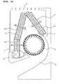
- FIG. 2 is an explanatory view showing air flows in the indoor unit shown in FIG. 1
- FIG. 3 is a characteristic graph showing the pressure loss and the air volume in a blower of the indoor unit shown in FIG. 1.
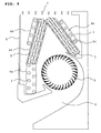
- the indoor unit of the air conditioner of the first embodiment includes an air inlet 7 of an upper grille, a heat exchanger 4 provided on the upstream side of air flows to surround a circulating fan 5, an air passage 6 defined by a casing for guiding air, which passes through the upper grille, the heat exchanger 4 and the circulating fan 5, to an air outlet 17, a condensed-water receiver 19 provided below the heat exchanger 4, and a housing including a front panel 8.
- air is mainly sucked from the upper side, and is blown toward the front lower side.
- the heat exchanger 4 includes a lower front heat exchanger 4a substantially vertically standing at the lower front of the indoor unit, an upper front heat exchanger 4b provided between the upper grille 7 and the lower front heat exchanger 4a and slightly tilted so as to make its upper portion positioned backward and its lower portion positioned forward, and a rear heat exchanger 4c provided to extend from the upper grille 7 to the lower rear of the indoor unit and slightly tilted so as to make its upper portion positioned forward and its lower portion positioned backward.
- These heat exchangers 4a to 4c are arranged to surround the circulating fan 5.
- the heat exchanger 4 is a fin-tube type heat exchanger including stacked plate fins 1, and heat transfer tubes 2 perpendicularly inserted into the plate fins 1.
- the pitch Fp in the stacking direction, thickness Ft, and width L of the plate fins 1 are 0.0011 m, 0.0001 m, and 0.0254 m, respectively.
- the wind velocity Uf at the front face of the heat exchanger 4 (mean wind velocity of the entire heat exchanger) is 1.0 m/s, and the distance Dp between the centers of the adjacent heat transfer tubes 2 is 0.0254 m.
- the plate fins 1 in the lower front heat exchanger 4a are flat 3 without louvered portions.
- Each of the plate fins 1 in the upper front heat exchanger 4b and the rear heat exchanger 4c has a plurality of trapezoidal louvered portions 3.
- the upper front heat exchanger 4b and the rear heat exchanger section 4c have the same shape, and are produced in the same production line.
- the plate fins 1 of the rear heat exchanger 4c are partly folded to form a folded portion 21 so that the rear heat exchanger 4c is placed inside a rear guider.
- the lower front heat exchanger 4a, the upper front heat exchanger 4b, and the rear heat exchanger 4c are not joined for the entire heat exchanger, but are separate from one another. Therefore, slit patterns of the heat exchangers 4a to 4c can be easily changed.
- FIG. 2 air flows in the heat exchanger 4, principally in the lower front heat exchanger 4a are shown by the arrows.
- the air flows produce a circulating vortex 9 in the circulating fan 5.
- Air does not pass through the front panel 8. Therefore, in a case in which louvered portions are provided in the entire of the lower front heat exchanger 4a, as in the upper front heat exchanger 4b and the rear heat exchanger 4c, the wind velocity near the lower front heat exchanger 4a is much lower than near the other heat exchanger 4b and 4c. For this reason, the lower front heat exchanger 4a does not have louvered portions in the first embodiment.
- the air pressure loss of the lower front heat exchanger 4a disposed remotely from the air inlet 7, of the fin-tube type heat exchangers 4a to 4c is set to be smaller than the air pressure losses of the upper front heat exchanger 4b and the rear heat exchanger 4c disposed near the air inlet 7. Since the air pressure loss of the lower front heat exchanger 4a is smaller than those of the upper front heat exchanger 4b and the rear heat exchanger 4c, the wind velocity on the lower side of the heat exchanger increases, and the intensity of turbulence generated around the vortex in the circulating fan increases. In this case, the static pressure in the vortex decreases, and the efficiency of the circulating fan increases.
- FIG. 3 is a characteristic graph showing the pressure loss ⁇ P and the air volume Ga when the circulating fan rotates at a constant speed of rotation.
- a solid line 10a shows the characteristic of the circulating fan when the lower front heat exchanger 4a is provided with louvered portions 3
- a broken line 10b shows the characteristic of the circulating fan 5 when the lower front heat exchanger 4a is not provided with louvered portions 3
- a solid line 11a shows the pressure loss characteristic of the heat exchanger when the lower front heat exchanger 4a is provided with louvered portions
- a broken line 11b shows the pressure loss characteristic of the heat exchanger when the lower front heat exchanger 4a is not provided with louvered portions.
- a black circle shows a unit operating point when the lower front heat exchanger 4a has louvered portions
- a white circle shows a unit operating point when the lower front heat exchanger 4a has no louvered portions.
- the drain efficiency for condensed water deposited on the plate fins 1 increases and the pressure loss decreases in comparison with the case where the louvered portions are provided.
- the portions of the plate fins 1 of the rear heat exchanger 4c which are in contact with the rear guider 18 are folded to form the folded portion 21. Therefore, the production line is simplified and the production cost can be greatly reduced, compared with a case in which the upper front heat exchanger 4b and the rear heat exchanger 4c are produced in different shapes.
- FIG. 4 shows a first modification of the first embodiment.
- auxiliary heat exchangers 4d and 4e having no louvered portions are added to the heat exchanger 4 of the first embodiment.
- the auxiliary heat exchangers 4d and 4e are provided, respectively, on the upper front heat exchanger 4b and the rear heat exchanger 4c disposed on the upstream side of air flows.
- advantages similar to those of the heat exchanger 4 shown in FIG. 1 are provided, and the performance of the heat exchanger is enhanced by the auxiliary heat exchangers 4d and 4e.
- FIG. 5 shows a second modification of the first embodiment.
- the auxiliary heat exchangers 4d and 4e shown in FIG. 4 have louvered portions 3.
- advantages similar to those of the heat exchanger 4 shown in FIG. 1 are provided, and the performance of the heat exchanger is further enhanced by the auxiliary heat exchangers 4d and 4e having the louvered portions 3.
- FIG. 6 shows a third modification of the first embodiment.
- a louvered portion 3 is provided only on the most downstream side in the row direction of louvered portions (shown by the right arrow in the figure).
- the upstream portion of the plate fin 1 is flat. Since the wind velocity at the most end and on the lowermost downstream side of the heat exchanger can be increased, advantages similar to those of the heat exchanger 4 shown in FIG. 1 can be provided.
- the louvered portion 3 is not provided on the most downstream side, a vortex having a low flow velocity is produced on the trailing side of the heat transfer tubes 2 in the air flow direction. This adversely affects the heat transfer performance, and increases noise in the circulating fan 5.
- the existence of the louvered portion 3 on the most downstream side can overcome these problems.
- FIG. 7 is a cross-sectional view of an indoor unit as a fourth modification of the first embodiment shown in FIG. 1.
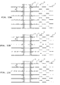
- FIGS. 8A, 8B, and 8C are sectional views of the heat exchanger shown in FIG. 7, respectively, taken along lines A-A, B-B, and C-C.
- This indoor unit is obtained by modifying the indoor unit shown in FIG. 1 in such a manner that a lower front heat exchanger 4a has louvered portions 3.
- the fin pitch ha between plate fins 1 in the lower front heat exchanger 4a is set to be longer than the fin pitches hb and hc between plate fins 1 in an upper front heat exchanger 4b and a rear heat exchanger 4c.
- the pressure loss caused by air flow through the lower front heat exchanger 4a is smaller than that through the upper front heat exchanger 4b and the rear heat exchanger4c, and the velocity of the air passing through the lower front heat exchanger 4a increases. Consequently, advantages similar to those of the heat exchanger 4 shown in FIG. 1 can be provided.
- FIGS. 9A, 9B, and 9C are sectional views of a heat exchanger in a fifth modification of the first embodiment, respectively, taken along lines A-A, B-B, and C-C in FIG. 7, in a manner similar to that in FIGS. 8A, 8B, and 8C.
- the height Sa of the louvered portions 3 of the plate fins 1 in the lower front heat exchanger 4a is set to be smaller than the heights Sb and Sc of louvered portions 3 of the plate fins 1 in the upper front heat exchanger 4b and the rear heat exchanger 4c.
- Other structures are the same as those in FIG. 7.
- the plate fins 1 of the lower front heat exchanger 4a, the upper front heat exchanger 4b, and the rear heat exchanger 4c are provided with the louvered portions 3, and the height Sa of the louvered portions 3 of the plate fins 1 in the lower front heat exchanger 4a is smaller than the heights Sb and Sc of the louvered portions 3 of the plate fins 1 in the upper front heat exchanger 4b and the rear heat exchanger 4c. Therefore, the pressure loss caused by air flow through the lower front heat exchanger 4a is smaller than that through the upper front heat exchanger 4b and the rear heat exchanger 4c, and the velocity of the air passing through the lower front heat exchanger 4a increases. Consequently, advantages similar to those of the heat exchanger 4 shown in FIG. 1 can be provided.
- the velocity of the air passing through the lower front heat exchanger 4a is further increased by making both the settings shown in FIGS. 8A to 8C and 9A to 9C for the plate fins 1.
- FIG. 10 is a cross-sectional view of an indoor unit as a sixth modification of the first embodiment.
- FIGS. 11A, 11B, and 11C are sectional views of a heat exchanger shown in FIG. 10, respectively, taken along lines A-A, B-B, and C-C.
- the plate fins 1 shown in FIG. 8 are used in the heat exchanger of the third modification shown in FIG. 6. That is, at the lowermost end of each plate fin 1 in a lower front heat exchanger 4a, a louvered portion 3 is provided only on the most downstream side in the louver pitch direction. The upstream portion of the plate fin 1 is flat. Plate fins 1 in an upper front heat exchanger 4b and a rear heat exchanger 4c are provided with louvered portions 3.
- the fin pitch ha between the plate fins 1 in the lower front heat exchanger 4a is set to be longer than the fin pitches hb and hc between the plate fins 1 in the upper front heat exchanger 4b and the rear heat exchanger 4c.
- the pressure loss caused by air flow through the lower front heat exchanger 4a is smaller than that through the upper front heat exchanger 4b and the rear heat exchanger 4c, and the velocity of the air passing through the lower front heat-exchanging section 4a increases. Consequently, advantages similar to those of the heat exchanger 4 shown in FIG. 1 can be provided.
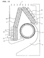
- FIG. 12 shows an indoor unit according to a seventh modification of the first embodiment. This is obtained by modifying the heat exchanger 4 of the indoor unit shown in Fig. 1.
- a lower front heat exchanger 4a is provided with louvered portions 3, in a manner similar to that in the other heat exchanger 4b and 4c.
- An auxiliary heat exchanger 4f is provided on the air upstream side of the lower front heat exchanger 4a.
- a space 20 through which air passes is provided between a front panel 8 and a condensed-water receiver 19.
- auxiliary heat exchanger 4f increases the pressure loss on the lower front side of the indoor unit, the wind velocity on that side increases because air flows in not only from an upper grille 7, but also from the space 20 between the front panel 8 and the condensed-water receiver 19. Consequently, advantages similar to those of the heat exchanger 4 of the first embodiment shown in FIG. 1 can be provided.
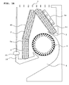
- FIG. 13 shows an indoor unit according to an eighth modification of the first embodiment.
- an auxiliary heat exchanger 4e is added on the upstream side of the rear heat exchanger 4c in the seventh modification shown in FIG. 12.
- advantages similar to those of the heat exchanger 4 in the seventh modification shown in Fig. 12 can be provided.
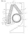
- FIG. 14 shows an indoor unit according to a ninth modification of the first embodiment.
- the auxiliary heat exchanger 4f is not provided on the lower front heat exchanger 4a as shown in FIG. 12, and only an auxiliary heat exchanger 4e is provided on the upstream side of the rear heat exchanger 4c.
- the wind velocity at the lower front heat exchanger 4a further increases, and advantages similar to those of the heat exchanger 4 in the seventh modification shown in FIG. 12 can be provided.
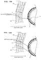
- FIG. 15 shows an indoor unit according to a tenth modification of the first embodiment shown in FIG. 1.
- louvered portions 3 of plate fins 1 in a lower front heat exchanger 4a which are provided closest to a circulating fan 5 and on the most downstream side in the row direction, are shaped like a parallelogram having opposite sides inclined downward at an angle ⁇ to the row direction.
- the other louvered portions 3 are trapezoidal.
- louvered portions 3 of plate fins 1 in the lower front heat exchanger 4a which are provided closest to the circulating fan 5 and on the most downstream side in the row direction, are shaped like a parallelogram having opposite sides inclined downward at the angle ⁇ to the row direction, air passing through the lower front heat exchanger 4a travels downward toward the circulating fan 5, and substantially follows the attack angle of blades in the circulating fan 5 as shown in FIG. 16B. Consequently, no separation vortex is produced on the pressure surface, and the input to the circulating fan 5 decreases.
- FIG. 17A is a partial cross-sectional view showing the vicinity of an upper contact portion between an upper front heat exchanger 4b and a rear heat exchanger 4c in a heat exchanger of a conventional indoor unit.
- a front surface of the indoor unit has a grille 7 through which air flows.
- the upper front heat exchanger 4b and the rear heat exchanger 4c are in line contact with each other, and a sealing member 16 is frequently used to prohibit air from passing through the contact portion in order to prevent the air from being concentrated near the contact portion without passing through the heat exchanger. In this case, the air completely flows around the sealing member 16. Therefore, there is a possibility that the heat transfer area will decrease, that the pressure loss will increase, and that the fan input will increase.
- an end face 35 of the upper heat exchanger 4b and a side face 36 of the rear heat exchanger 4c are in face contact, as shown in FIG. 17B. Since air also flows through the contact portion between the heat exchangers 4b and 4c, the pressure loss is smaller than in the conventional heat exchanger, and the heat transfer area is not reduced. In addition, since air does not flow through the panel 8, the wind velocity near the contact portion between the upper front heat exchanger 4b and the rear heat exchanger 4c is much higher than in the case where a grille through which air flows is provided on the front side. Therefore, the above-described advantages are improved. Such an upper contact between the upper front heat exchanger 4b and the rear heat exchanger 4c can also be applied to the above-described structures (counter measures) for reducing the air pressure loss of the lower front heat-exchanging section 4a.
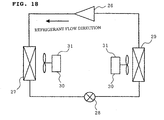
- FIG. 18 is a circuit diagram of a refrigerant circuit in an air conditioner having the above-described heat exchanger of the first embodiment of the present invention.
- the refrigerant circuit includes a compressor 26, a condensing heat exchanger 27, a throttle 28, an evaporating heat exchanger 29, and a fan 30.
- the energy efficiency of the air conditioner can be enhanced by applying the heat exchanger of the first embodiment to the condensing heat exchanger 27, the evaporating heat exchanger 29, or both thereof.
- HCFC HCFC
- HFC HFC
- the plate fins 1 and the heat transfer tubes 2 are frequently made of different materials, they may be made of the same material such as copper or aluminum. In this case, the plate fins 1 and the heat transfer tubes 2 can be brazed. This dramatically increases the contact heat transfer coefficient therebetween, and greatly enhances the heat exchange performance. Moreover, recyclability is enhanced.
- the plate fins 1 When the plate fins 1 are closely bonded to the heat transfer tubes 2 by furnace brazing, they are coated with a hydrophilic material after brazing. This prevents the hydrophilic material from being burnt during brazing.
- the heat transfer performance can be enhanced by applying a heat-radiating coating, which promotes radiant heat transfer, onto the plate fins 1.
- any refrigeration oil such as mineral oil, alkylbenzene oil, ester oil, ether oil, or fluorine oil, regardless of whether the oil can mix the refrigerant.
Landscapes
- Engineering & Computer Science (AREA)
- Physics & Mathematics (AREA)
- Mechanical Engineering (AREA)
- General Engineering & Computer Science (AREA)
- Thermal Sciences (AREA)
- Chemical & Material Sciences (AREA)
- Combustion & Propulsion (AREA)
- Geometry (AREA)
- Air Filters, Heat-Exchange Apparatuses, And Housings Of Air-Conditioning Units (AREA)
Applications Claiming Priority (2)
| Application Number | Priority Date | Filing Date | Title |
|---|---|---|---|
| JP2004070787 | 2004-03-12 | ||
| PCT/JP2005/003745 WO2005088201A1 (ja) | 2004-03-12 | 2005-03-04 | 空気調和機の室内機 |
Publications (3)
| Publication Number | Publication Date |
|---|---|
| EP1659344A1 true EP1659344A1 (de) | 2006-05-24 |
| EP1659344A4 EP1659344A4 (de) | 2008-09-17 |
| EP1659344B1 EP1659344B1 (de) | 2011-05-11 |
Family
ID=34975682
Family Applications (1)
| Application Number | Title | Priority Date | Filing Date |
|---|---|---|---|
| EP05720017A Active EP1659344B1 (de) | 2004-03-12 | 2005-03-04 | Innenraumeinheit einer klimaanlage |
Country Status (5)
| Country | Link |
|---|---|
| US (1) | US8156999B2 (de) |
| EP (1) | EP1659344B1 (de) |
| CN (1) | CN100347491C (de) |
| ES (1) | ES2366583T3 (de) |
| WO (1) | WO2005088201A1 (de) |
Cited By (2)
| Publication number | Priority date | Publication date | Assignee | Title |
|---|---|---|---|---|
| EP3315869A4 (de) * | 2015-06-25 | 2019-03-27 | Toshiba Carrier Corporation | Klimaanlage und wärmetauscher vom deckeninstallationstyp |
| EP3637002A4 (de) * | 2017-07-07 | 2020-05-20 | Samsung Electronics Co., Ltd. | Wärmetauscher und innenraumgerät damit |
Families Citing this family (11)
| Publication number | Priority date | Publication date | Assignee | Title |
|---|---|---|---|---|
| JP4796814B2 (ja) * | 2005-10-20 | 2011-10-19 | 東芝キヤリア株式会社 | 熱交換器と、空気調和機の室内機 |
| KR101608981B1 (ko) * | 2007-10-22 | 2016-04-04 | 엘지전자 주식회사 | 공기 조화기 |
| JP4610626B2 (ja) * | 2008-02-20 | 2011-01-12 | 三菱電機株式会社 | 天井埋め込み型空気調和機に配置される熱交換器及び天井埋め込み型空気調和機 |
| JP5409544B2 (ja) * | 2010-08-04 | 2014-02-05 | 三菱電機株式会社 | 空気調和機の室内機、及び空気調和機 |
| CN102478284B (zh) * | 2010-11-26 | 2016-08-03 | 乐金电子(天津)电器有限公司 | 柜式空调室内机 |
| KR101240512B1 (ko) * | 2011-05-19 | 2013-03-11 | (주)가교테크 | 냉각/제습열 회수기술을 이용한 에어컨 |
| CN103900153B (zh) * | 2012-12-28 | 2018-06-15 | 松下电器产业株式会社 | 空气调节器 |
| US20150153111A1 (en) * | 2013-12-02 | 2015-06-04 | Carrier Corporation | Indoor coil |
| WO2021077649A1 (zh) * | 2019-10-23 | 2021-04-29 | 广东美的暖通设备有限公司 | 换热器翅片、换热器、室内机和空调器 |
| GB202019056D0 (en) * | 2020-12-03 | 2021-01-20 | Bae Systems Plc | Heat exchanger |
| US11808530B2 (en) | 2021-10-20 | 2023-11-07 | Rheem Manufacturing Company | Louvered fin |
Citations (5)
| Publication number | Priority date | Publication date | Assignee | Title |
|---|---|---|---|---|
| JPH09264556A (ja) * | 1996-03-29 | 1997-10-07 | Fujitsu General Ltd | 空気調和機の熱交換器 |
| EP0821203A2 (de) * | 1993-09-29 | 1998-01-28 | Mitsubishi Denki Kabushiki Kaisha | Sonder-Klimagerät |
| JPH11183077A (ja) * | 1997-12-19 | 1999-07-06 | Fujitsu General Ltd | 空気調和機の室内機 |
| JP2002054840A (ja) * | 2000-08-09 | 2002-02-20 | Hitachi Ltd | 空気調和機 |
| EP1703216A2 (de) * | 2005-02-22 | 2006-09-20 | Matsushita Electric Industrial Co., Ltd. | Klimaanlage |
Family Cites Families (31)
| Publication number | Priority date | Publication date | Assignee | Title |
|---|---|---|---|---|
| US3438433A (en) * | 1967-05-09 | 1969-04-15 | Hudson Eng Co | Plate fins |
| JPS62187218U (de) | 1986-05-19 | 1987-11-28 | ||
| JPH02166392A (ja) | 1988-12-16 | 1990-06-27 | Matsushita Refrig Co Ltd | 熱交換器 |
| JPH03211396A (ja) | 1990-01-16 | 1991-09-17 | Matsushita Electric Ind Co Ltd | 空気調和機 |
| JPH0420792A (ja) * | 1990-05-11 | 1992-01-24 | Mitsubishi Electric Corp | 空調用熱交換器 |
| JP2901338B2 (ja) | 1990-11-22 | 1999-06-07 | 昭和アルミニウム株式会社 | 熱交換器 |
| JPH0752485Y2 (ja) | 1991-01-21 | 1995-11-29 | 株式会社富士通ゼネラル | 空気調和機の室内ユニット |
| US5277715A (en) | 1992-06-04 | 1994-01-11 | Micron Semiconductor, Inc. | Method of reducing particulate concentration in process fluids |
| CN2155518Y (zh) * | 1993-05-31 | 1994-02-09 | 齐文峰 | 室内外双向换气机 |
| JPH073204A (ja) | 1993-06-16 | 1995-01-06 | Dainippon Ink & Chem Inc | 酸硬化用水性アミノアルキド樹脂組成物 |
| JP3233551B2 (ja) | 1995-05-22 | 2001-11-26 | 東芝キヤリア株式会社 | 空気調和機 |
| JP3261932B2 (ja) | 1995-07-28 | 2002-03-04 | 株式会社日立製作所 | 空気調和機 |
| JP3629090B2 (ja) | 1996-03-28 | 2005-03-16 | 三菱電機株式会社 | 空気調和機 |
| JPH1038302A (ja) * | 1996-07-19 | 1998-02-13 | Fujitsu General Ltd | 空気調和機の室内ユニット |
| KR100256402B1 (ko) * | 1996-12-30 | 2000-05-15 | 윤종용 | 공기조화기의 열교환기 |
| JPH10220788A (ja) | 1997-02-04 | 1998-08-21 | Daikin Ind Ltd | 空気清浄フィルタ付き室内機 |
| JP3567665B2 (ja) * | 1997-02-04 | 2004-09-22 | 松下電器産業株式会社 | 電気やぐらこたつ |
| JPH1123179A (ja) * | 1997-06-30 | 1999-01-26 | Matsushita Electric Ind Co Ltd | フィン付熱交換器 |
| JPH11281280A (ja) * | 1998-03-27 | 1999-10-15 | Sanyo Electric Co Ltd | 可変スリット熱交換器 |
| JP2000179993A (ja) | 1998-12-16 | 2000-06-30 | Matsushita Electric Ind Co Ltd | 空気調和機の熱交換器 |
| JP2001201170A (ja) | 2000-01-24 | 2001-07-27 | Mitsubishi Heavy Ind Ltd | 室内ユニットの製造方法、室内ユニットおよび空気調和装置 |
| JP2001324159A (ja) | 2000-05-16 | 2001-11-22 | Matsushita Electric Ind Co Ltd | 空気調和機の室内ユニット |
| JP2002147790A (ja) | 2000-11-06 | 2002-05-22 | Fujitsu General Ltd | 空気調和機 |
| JP2002213764A (ja) * | 2001-01-19 | 2002-07-31 | Fujitsu General Ltd | 空気調和機 |
| JP2002243383A (ja) | 2001-02-19 | 2002-08-28 | Mitsubishi Electric Corp | 熱交換器およびこれを用いた空気調和機 |
| JP2003028594A (ja) * | 2001-07-16 | 2003-01-29 | Daikin Ind Ltd | 熱交換器及び空気調和機 |
| JP4092919B2 (ja) | 2002-01-25 | 2008-05-28 | 株式会社日立製作所 | 空気調和機 |
| JP2002250537A (ja) | 2002-02-26 | 2002-09-06 | Hitachi Ltd | 空気調和機 |
| JP2004037025A (ja) | 2002-07-05 | 2004-02-05 | Hitachi Home & Life Solutions Inc | 空気調和機 |
| JP3613272B2 (ja) | 2003-02-03 | 2005-01-26 | ダイキン工業株式会社 | 空気調和機 |
| JP6084875B2 (ja) * | 2013-03-28 | 2017-02-22 | 京セラ株式会社 | 入力機能付き表示装置、および電子機器 |
-
2005
- 2005-03-04 WO PCT/JP2005/003745 patent/WO2005088201A1/ja not_active Application Discontinuation
- 2005-03-04 US US10/573,992 patent/US8156999B2/en active Active
- 2005-03-04 CN CNB2005800000551A patent/CN100347491C/zh active Active
- 2005-03-04 ES ES05720017T patent/ES2366583T3/es active Active
- 2005-03-04 EP EP05720017A patent/EP1659344B1/de active Active
Patent Citations (5)
| Publication number | Priority date | Publication date | Assignee | Title |
|---|---|---|---|---|
| EP0821203A2 (de) * | 1993-09-29 | 1998-01-28 | Mitsubishi Denki Kabushiki Kaisha | Sonder-Klimagerät |
| JPH09264556A (ja) * | 1996-03-29 | 1997-10-07 | Fujitsu General Ltd | 空気調和機の熱交換器 |
| JPH11183077A (ja) * | 1997-12-19 | 1999-07-06 | Fujitsu General Ltd | 空気調和機の室内機 |
| JP2002054840A (ja) * | 2000-08-09 | 2002-02-20 | Hitachi Ltd | 空気調和機 |
| EP1703216A2 (de) * | 2005-02-22 | 2006-09-20 | Matsushita Electric Industrial Co., Ltd. | Klimaanlage |
Non-Patent Citations (1)
| Title |
|---|
| See also references of WO2005088201A1 * |
Cited By (3)
| Publication number | Priority date | Publication date | Assignee | Title |
|---|---|---|---|---|
| EP3315869A4 (de) * | 2015-06-25 | 2019-03-27 | Toshiba Carrier Corporation | Klimaanlage und wärmetauscher vom deckeninstallationstyp |
| EP3637002A4 (de) * | 2017-07-07 | 2020-05-20 | Samsung Electronics Co., Ltd. | Wärmetauscher und innenraumgerät damit |
| US11365892B2 (en) | 2017-07-07 | 2022-06-21 | Samsung Electronics Co., Ltd. | Heat exchanger and indoor unit having the same |
Also Published As
| Publication number | Publication date |
|---|---|
| ES2366583T3 (es) | 2011-10-21 |
| EP1659344A4 (de) | 2008-09-17 |
| CN100347491C (zh) | 2007-11-07 |
| US20060272349A1 (en) | 2006-12-07 |
| US8156999B2 (en) | 2012-04-17 |
| CN1764807A (zh) | 2006-04-26 |
| WO2005088201A1 (ja) | 2005-09-22 |
| EP1659344B1 (de) | 2011-05-11 |
Similar Documents
| Publication | Publication Date | Title |
|---|---|---|
| EP1659344B1 (de) | Innenraumeinheit einer klimaanlage | |
| JP4081688B2 (ja) | 空気調和機の室内機 | |
| JP4679542B2 (ja) | フィンチューブ熱交換器、およびそれを用いた熱交換器ユニット並びに空気調和機 | |
| JP4749373B2 (ja) | 空気調和機 | |
| US8276652B2 (en) | High performance louvered fin for heat exchanger | |
| JP5523495B2 (ja) | フィンチューブ型熱交換器及び冷凍サイクル装置 | |
| JP3720208B2 (ja) | 熱交換器及びそれを用いた空調冷凍装置 | |
| JP4196974B2 (ja) | 空気調和機 | |
| JP2002139282A (ja) | 熱交換器、冷凍空調装置、熱交換器の製造方法 | |
| WO2007017969A1 (ja) | 空気調和機及び空気調和機の製造方法 | |
| JP5312413B2 (ja) | フィンチューブ熱交換器及びそれを用いた冷凍サイクル装置 | |
| WO2019009158A1 (ja) | 熱交換器 | |
| JP2010249343A (ja) | フィンチューブ型熱交換器及びこれを用いた空気調和機 | |
| JPH0791873A (ja) | フィンアンドチューブ形熱交換器 | |
| JP2011112315A (ja) | フィンチューブ型熱交換器及びこれを用いた空気調和機 | |
| JP3945575B2 (ja) | フィンチューブ型熱交換器およびこれを用いた冷凍サイクル空調装置 | |
| JPH11183076A (ja) | 熱交換器 | |
| JP4186359B2 (ja) | 熱交換器および該熱交換器を備えた空調冷凍装置 | |
| CN210119132U (zh) | 用于换热器的翅片、换热器及空调室外机 | |
| JP6621928B2 (ja) | 熱交換器および空気調和装置 | |
| JP5072983B2 (ja) | フィンチューブ型熱交換器およびこれを用いた空調装置 | |
| JP4143973B2 (ja) | 空気調和機 | |
| JP3170545B2 (ja) | 空気調和機 | |
| JP3170547B2 (ja) | 空気調和機 | |
| JP7006376B2 (ja) | 熱交換器 |
Legal Events
| Date | Code | Title | Description |
|---|---|---|---|
| PUAI | Public reference made under article 153(3) epc to a published international application that has entered the european phase |
Free format text: ORIGINAL CODE: 0009012 |
|
| 17P | Request for examination filed |
Effective date: 20060214 |
|
| AK | Designated contracting states |
Kind code of ref document: A1 Designated state(s): ES IT |
|
| RIN1 | Information on inventor provided before grant (corrected) |
Inventor name: ISHIBASHI, AKIRA,C/O MITSUBISHI DENKI K.K. Inventor name: OKAZAWA, HIROKI,C/O MITSUBISHI DENKI KABUSHIKI KK Inventor name: NAKAYAMA, MASAHIRO,C/O MITSUBISHI DENKI K.K. Inventor name: SAITOU, TADASHI,C/O MITSUBISHI DENKI KABUSHIKI KK |
|
| DAX | Request for extension of the european patent (deleted) | ||
| RBV | Designated contracting states (corrected) |
Designated state(s): ES IT |
|
| A4 | Supplementary search report drawn up and despatched |
Effective date: 20080818 |
|
| 17Q | First examination report despatched |
Effective date: 20090420 |
|
| GRAP | Despatch of communication of intention to grant a patent |
Free format text: ORIGINAL CODE: EPIDOSNIGR1 |
|
| GRAC | Information related to communication of intention to grant a patent modified |
Free format text: ORIGINAL CODE: EPIDOSCIGR1 |
|
| GRAS | Grant fee paid |
Free format text: ORIGINAL CODE: EPIDOSNIGR3 |
|
| RIN1 | Information on inventor provided before grant (corrected) |
Inventor name: ISHIBASHI, AKIRA,C/O MITSUBISHI DENKI KABUSHIKI KA Inventor name: OKAZAWA, HIROKI,C/O MITSUBISHI DENKI KABUSHIKI KAI Inventor name: SAITOU, TADASHI,C/O MITSUBISHI DENKI KABUSHIKI KAI Inventor name: NAKAYAMA, MASAHIRO,C/O MITSUBISHI DENKI KABUSHIKI |
|
| GRAA | (expected) grant |
Free format text: ORIGINAL CODE: 0009210 |
|
| AK | Designated contracting states |
Kind code of ref document: B1 Designated state(s): ES IT |
|
| REG | Reference to a national code |
Ref country code: ES Ref legal event code: FG2A Ref document number: 2366583 Country of ref document: ES Kind code of ref document: T3 Effective date: 20111021 |
|
| PLBE | No opposition filed within time limit |
Free format text: ORIGINAL CODE: 0009261 |
|
| STAA | Information on the status of an ep patent application or granted ep patent |
Free format text: STATUS: NO OPPOSITION FILED WITHIN TIME LIMIT |
|
| 26N | No opposition filed |
Effective date: 20120214 |
|
| REG | Reference to a national code |
Ref country code: ES Ref legal event code: GC2A Effective date: 20140416 |
|
| PG25 | Lapsed in a contracting state [announced via postgrant information from national office to epo] |
Ref country code: IT Free format text: LAPSE BECAUSE OF NON-PAYMENT OF DUE FEES Effective date: 20150304 |
|
| PG25 | Lapsed in a contracting state [announced via postgrant information from national office to epo] |
Ref country code: IT Free format text: LAPSE BECAUSE OF NON-PAYMENT OF DUE FEES Effective date: 20150304 |
|
| PGRI | Patent reinstated in contracting state [announced from national office to epo] |
Ref country code: IT Effective date: 20180104 |
|
| P01 | Opt-out of the competence of the unified patent court (upc) registered |
Effective date: 20230512 |
|
| PGFP | Annual fee paid to national office [announced via postgrant information from national office to epo] |
Ref country code: IT Payment date: 20240212 Year of fee payment: 20 |
|
| PGFP | Annual fee paid to national office [announced via postgrant information from national office to epo] |
Ref country code: ES Payment date: 20240401 Year of fee payment: 20 |