EP1658453B2 - Boite de vitesses automatique a plusieurs etages comportant trois trains planetaires - Google Patents
Boite de vitesses automatique a plusieurs etages comportant trois trains planetaires Download PDFInfo
- Publication number
- EP1658453B2 EP1658453B2 EP04740362A EP04740362A EP1658453B2 EP 1658453 B2 EP1658453 B2 EP 1658453B2 EP 04740362 A EP04740362 A EP 04740362A EP 04740362 A EP04740362 A EP 04740362A EP 1658453 B2 EP1658453 B2 EP 1658453B2
- Authority
- EP
- European Patent Office
- Prior art keywords
- shifting
- shifting element
- planetary gear
- servo device
- disc
- Prior art date
- Legal status (The legal status is an assumption and is not a legal conclusion. Google has not performed a legal analysis and makes no representation as to the accuracy of the status listed.)
- Expired - Fee Related
Links
Images


Classifications
-
- F—MECHANICAL ENGINEERING; LIGHTING; HEATING; WEAPONS; BLASTING
- F16—ENGINEERING ELEMENTS AND UNITS; GENERAL MEASURES FOR PRODUCING AND MAINTAINING EFFECTIVE FUNCTIONING OF MACHINES OR INSTALLATIONS; THERMAL INSULATION IN GENERAL
- F16H—GEARING
- F16H3/00—Toothed gearings for conveying rotary motion with variable gear ratio or for reversing rotary motion
- F16H3/44—Toothed gearings for conveying rotary motion with variable gear ratio or for reversing rotary motion using gears having orbital motion
- F16H3/62—Gearings having three or more central gears
- F16H3/66—Gearings having three or more central gears composed of a number of gear trains without drive passing from one train to another
-
- F—MECHANICAL ENGINEERING; LIGHTING; HEATING; WEAPONS; BLASTING
- F16—ENGINEERING ELEMENTS AND UNITS; GENERAL MEASURES FOR PRODUCING AND MAINTAINING EFFECTIVE FUNCTIONING OF MACHINES OR INSTALLATIONS; THERMAL INSULATION IN GENERAL
- F16D—COUPLINGS FOR TRANSMITTING ROTATION; CLUTCHES; BRAKES
- F16D25/00—Fluid-actuated clutches
- F16D25/06—Fluid-actuated clutches in which the fluid actuates a piston incorporated in, i.e. rotating with the clutch
- F16D25/062—Fluid-actuated clutches in which the fluid actuates a piston incorporated in, i.e. rotating with the clutch the clutch having friction surfaces
- F16D25/063—Fluid-actuated clutches in which the fluid actuates a piston incorporated in, i.e. rotating with the clutch the clutch having friction surfaces with clutch members exclusively moving axially
- F16D25/0635—Fluid-actuated clutches in which the fluid actuates a piston incorporated in, i.e. rotating with the clutch the clutch having friction surfaces with clutch members exclusively moving axially with flat friction surfaces, e.g. discs
- F16D25/0638—Fluid-actuated clutches in which the fluid actuates a piston incorporated in, i.e. rotating with the clutch the clutch having friction surfaces with clutch members exclusively moving axially with flat friction surfaces, e.g. discs with more than two discs, e.g. multiple lamellae
-
- F—MECHANICAL ENGINEERING; LIGHTING; HEATING; WEAPONS; BLASTING
- F16—ENGINEERING ELEMENTS AND UNITS; GENERAL MEASURES FOR PRODUCING AND MAINTAINING EFFECTIVE FUNCTIONING OF MACHINES OR INSTALLATIONS; THERMAL INSULATION IN GENERAL
- F16D—COUPLINGS FOR TRANSMITTING ROTATION; CLUTCHES; BRAKES
- F16D25/00—Fluid-actuated clutches
- F16D25/10—Clutch systems with a plurality of fluid-actuated clutches
-
- F—MECHANICAL ENGINEERING; LIGHTING; HEATING; WEAPONS; BLASTING
- F16—ENGINEERING ELEMENTS AND UNITS; GENERAL MEASURES FOR PRODUCING AND MAINTAINING EFFECTIVE FUNCTIONING OF MACHINES OR INSTALLATIONS; THERMAL INSULATION IN GENERAL
- F16H—GEARING
- F16H3/00—Toothed gearings for conveying rotary motion with variable gear ratio or for reversing rotary motion
- F16H3/44—Toothed gearings for conveying rotary motion with variable gear ratio or for reversing rotary motion using gears having orbital motion
-
- F—MECHANICAL ENGINEERING; LIGHTING; HEATING; WEAPONS; BLASTING
- F16—ENGINEERING ELEMENTS AND UNITS; GENERAL MEASURES FOR PRODUCING AND MAINTAINING EFFECTIVE FUNCTIONING OF MACHINES OR INSTALLATIONS; THERMAL INSULATION IN GENERAL
- F16C—SHAFTS; FLEXIBLE SHAFTS; ELEMENTS OR CRANKSHAFT MECHANISMS; ROTARY BODIES OTHER THAN GEARING ELEMENTS; BEARINGS
- F16C19/00—Bearings with rolling contact, for exclusively rotary movement
- F16C19/54—Systems consisting of a plurality of bearings with rolling friction
- F16C19/541—Systems consisting of juxtaposed rolling bearings including at least one angular contact bearing
- F16C19/542—Systems consisting of juxtaposed rolling bearings including at least one angular contact bearing with two rolling bearings with angular contact
- F16C19/543—Systems consisting of juxtaposed rolling bearings including at least one angular contact bearing with two rolling bearings with angular contact in O-arrangement
-
- F—MECHANICAL ENGINEERING; LIGHTING; HEATING; WEAPONS; BLASTING
- F16—ENGINEERING ELEMENTS AND UNITS; GENERAL MEASURES FOR PRODUCING AND MAINTAINING EFFECTIVE FUNCTIONING OF MACHINES OR INSTALLATIONS; THERMAL INSULATION IN GENERAL
- F16C—SHAFTS; FLEXIBLE SHAFTS; ELEMENTS OR CRANKSHAFT MECHANISMS; ROTARY BODIES OTHER THAN GEARING ELEMENTS; BEARINGS
- F16C2361/00—Apparatus or articles in engineering in general
- F16C2361/61—Toothed gear systems, e.g. support of pinion shafts
-
- F—MECHANICAL ENGINEERING; LIGHTING; HEATING; WEAPONS; BLASTING
- F16—ENGINEERING ELEMENTS AND UNITS; GENERAL MEASURES FOR PRODUCING AND MAINTAINING EFFECTIVE FUNCTIONING OF MACHINES OR INSTALLATIONS; THERMAL INSULATION IN GENERAL
- F16H—GEARING
- F16H2200/00—Transmissions for multiple ratios
- F16H2200/003—Transmissions for multiple ratios characterised by the number of forward speeds
- F16H2200/0052—Transmissions for multiple ratios characterised by the number of forward speeds the gear ratios comprising six forward speeds
-
- F—MECHANICAL ENGINEERING; LIGHTING; HEATING; WEAPONS; BLASTING
- F16—ENGINEERING ELEMENTS AND UNITS; GENERAL MEASURES FOR PRODUCING AND MAINTAINING EFFECTIVE FUNCTIONING OF MACHINES OR INSTALLATIONS; THERMAL INSULATION IN GENERAL
- F16H—GEARING
- F16H2200/00—Transmissions for multiple ratios
- F16H2200/20—Transmissions using gears with orbital motion
- F16H2200/2002—Transmissions using gears with orbital motion characterised by the number of sets of orbital gears
- F16H2200/201—Transmissions using gears with orbital motion characterised by the number of sets of orbital gears with three sets of orbital gears
Definitions
- the present invention relates to a multi-stage automatic transmission with at least three individual planetary gear sets and at least five switching elements, according to the preamble of patent claim 1 and of patent claim 2.
- a drive shaft of the automatic transmission is constantly connected to a sun gear of the second planetary gear set. Furthermore, the drive shaft via the first clutch with a sun gear of the first planetary gear set and / or via the second clutch with a web of the first planetary gear set is connectable. Additionally or alternatively, the sun gear of the first planetary gear set via the first brake with a housing of the automatic transmission and / or the web of the first planetary gear set via the second brake with the housing and / or a sun gear of the third planetary gear set via the third brake to the housing connectable.
- an output shaft of the automatic transmission is constantly connected to a web of the third planetary and a ring gear of the first planetary, and that the web of the first planetary gear constantly with a ring gear of the second planetary gear set and a web of the second planetary gear set constantly a ring gear of the third planetary gear set is connected.
- the drive and the output shaft can be arranged both coaxially with each other on opposite sides of the gear housing, as well as axially parallel on the same side of the gear housing.
- the output shaft is constantly connected to the web of the second planetary gear set and the ring gear of the first planetary gear set, that the web of the first planetary gear set is constantly connected to the ring gear of the third planetary gear set, and that the ring gear of the second planetary gear set constantly connected to the bridge of the third planetary gear set.
- Such a design is particularly suitable for a coaxial arrangement of input and output shafts.
- the spatial arrangement of the planetary gear sets proposes the DE 199 12 480 A1 to arrange the three planetary gear sets coaxially in series next to each other, wherein the second planetary gear set is disposed axially between the first and third planetary gear set.
- both clutches are arranged on the side facing away from the third planetary gear set of the first planetary gear, wherein the first clutch axially adjacent to the first brake and disposed closer to the first planetary gear than the second clutch.
- both clutches are arranged on the side of the third planetary gearset facing away from the first planetary gearset, wherein the second clutch is arranged closer to the third planetary gearset than the first clutch and axially adjacent to an output spur gear operatively connected to the output shaft, which in turn is disposed on the side of the third brake remote from the third planetary gear set.
- the present invention is based on the object for which from the prior art of DE 199 12 480 A1 known automatic transmission represent alternative component arrangements, with the most compact transmission structure.
- the automatic transmission should be used in a motor vehicle with non-coaxial with each other arranged drive and output shaft application by comparatively simple modifications as possible but also be used with coaxial drive and output shaft.
- the inventive multi-stage automatic transmission on at least three coupled single planetary gear sets, which are arranged coaxially to one another and spatially next to each other, wherein the second planetary gear set is always arranged spatially between the first and third planetary gear.
- the automatic transmission according to the invention has at least five switching elements on.
- a sun gear of the third planetary gear set can be fixed via the first switching element designed as a brake on a gear housing of the automatic transmission.
- a drive shaft of the automatic transmission is constantly connected to a sun gear of the second planetary gear set.
- the drive shaft via the clutch formed as a second switching element with a sun gear of the first planetary gear set and additionally or alternatively via the coupling formed as a fifth switching element with a web of the first planetary gear set is connectable.
- An output shaft of the multi-stage automatic transmission is constantly operatively connected to a ring gear of the first planetary gear set, wherein the ring gear of the first planetary gear set is additionally permanently connected either to a web of the third planetary or a web of the second planetary gear set.
- the web of the first planetary gear set (depending on the wheelset concept) additionally either constantly connected to the ring gear of the second planetary gear set or constantly with the ring gear of the third planetary gear set. If the ring gear of the first planetary gear set and land of the third planetary gearset and output shaft are coupled together, the land of the second planetary gear set is constantly connected to a ring gear of the third planetary gear set and the land of the first planetary gear set is constantly connected to a ring gear of the second planetary gear set.
- the land of the third planetary gear set is constantly connected to the ring gear of the second planetary gear set and the land of the first planetary gear set is continuously connected to the ring gear of the third planetary gear set.
- the second switching element via which the drive shaft is connectable to the sun gear of the first planetary gear set
- the fifth switching element via which the drive shaft is connectable to the web of the first planetary gear set
- this assembly has at least one each disk set of the second and fifth switching element, a common for the second and fifth switching element disk carrier for receiving outer or lining disks of the disk sets of the second and fifth switching element, and one servo device for actuating the respective disk sets of the second or fifth switching element on.
- the disk set of the second switching element is arranged on a larger diameter than the disk set of the fifth switching element.
- a friction surface inner diameter of the lining disks of the disk set of the second shifting element is larger than a friction surface outside diameter of the lining disks of the disk set of the fifth shifting element.
- this assembly having the second and fifth switching element is arranged adjacent to the first planetary gear set, on the side of the first planetary gearset facing away from the second (middle) planetary gearset.
- the disk set of the second switching element is spatially arranged at least substantially radially over the disk set of the fifth switching element. In this case, then both disk sets of the second and fifth switching element are arranged axially adjacent to the first planetary gear.
- the disk set of the second switching element spatially seen at least partially axially adjacent to the disk set of the fifth switching element is arranged.
- the disk set of the second switching element in the axial direction is arranged at least partially radially above the first planetary gear set and the disk set of the fifth switching element is arranged at least partially axially next to the first planetary gear set in the radial direction.
- the second and fifth switching element common plate carrier forms a clutch space, within which the disk set and the servo device of the fifth switching element are arranged.
- the servos of the second and fifth switching element each have at least one pressure chamber and a piston, these two pressure chambers are separated from each other by a lateral surface of the common for the second and fifth switching element disc carrier.
- the actuating direction of the servos of the second and fifth switching element is directed opposite, then actuates the servo of the fifth switching element, the fins of the fifth switching element axially in the direction of the first planetary gear set, and the servo device of the second switching element the lamellae of the second switching element axially in the direction opposite to the first planetary gear set.
- the pressure chambers of the servos of the second and fifth switching element are in this case arranged axially next to each other, expediently both directly adjacent to the lateral surface of the common for the second and fifth switching element plate carrier.
- the piston of the servo device of the second switching element then has a force acting on the disk set of the second switching element actuation punch, which completely overlaps the disk set of the second switching element in the axial direction.
- pressure equalization spaces of the servo devices of the second and fifth switching element are then respectively arranged on the side of the respective pressure chamber, which faces away from the plate carrier outer surface.
- the pressure space of the servo device of the fifth switching element and the pressure compensation space of the servo device of the second switching element directly adjoin the lateral surface of the plate carrier common to the second and fifth switching elements at.
- the pressure chamber of the servo device of the second switching element is then arranged on the side of the pressure compensation space of the servo device of the second switching element which is opposite the disk carrier lateral surface.
- pressure compensation space of the servo device of the fifth switching element is then arranged corresponding to the disk carrier surface, opposite side of the pressure chamber of the fifth switching element.
- the third switching element via which the sun gear of the first planetary gear set on the transmission housing can be fixed, and / or the fourth switching element, via which the web of the first planetary gear set (and connected to this web ring gear of the second or third Planetenradsatzes) can be fixed to the gear housing, spatially arranged in a region radially above the side by side arranged in series Planetenrad mechanismsn.
- the third switching element is preferably arranged radially above the first and / or second (middle) planetary gear set as viewed in the axial direction.
- the fourth switching element is preferably arranged radially above the second (middle) and / or third planetary gear set as viewed in the axial direction.
- the third switching element is therefore preferably arranged closer to the assembly comprising the second and fifth switching elements than the fourth switching element.
- the third and fourth switching element can also be combined as a preassembled module, for example, with a common outer housing carrier fixed outer disk carrier and axially juxtaposed disk packs, in which common outer disk carrier and the servo devices of the third and fourth can be at least partially integrated.
- the first switching element via which the sun gear of the third planetary gear set can be fixed to the transmission housing, arranged on the side of the third planetary gear, which is the second (or fifth) switching element opposite.
- the first switching element adjacent to an outer wall of the gear housing and a spur gear or chain drive spatially seen axially between the third planetary gear and to arrange the first switching element.
- another spur gear of the spur gear or a second sprocket of the chain drive is connected to the output shaft of the automatic transmission.
- a servo device and / or a plate carrier of the brake element designed as a first switching element can be integrated into an outer wall or a housing-fixed cover of the gear housing.
- the first switching element is at least partially disposed axially adjacent to the third planetary gear set on the opposite side of the second planetary gear set, and that the spur gear or chain drive spatially on the other side of the first switching element (that is, on the opposite side of the third planetary gearset of the first switching element) is arranged.
- the first switching element designed as a brake can be arranged spatially next to the fourth switching element, which is also designed as a brake, in which case preferably a same plate diameter is provided for these two switching elements (identical parts concept).
- the Stirntrieb- or chain drive arrangement can also be provided that the first switching element spatially seen at least substantially radially disposed over the third planetary gear, and that the Stirntrieb- or chain drive spatially seen on the opposite side of the second planetary gear set of the third planetary gear set axially adjacent to the third planetary gear set and the first switching element.
- the output shaft of the automatic transmission arranged adjacent to the third planetary gear first switching element and the sun gear of the third planetary centrally in the axial direction and spatially in the range axially between the second and third planetary with the Bridge of the third and second planetary gear set is connected.
- the component assembly according to the invention over the prior art of DE 199 12 480 A1 achieved a significantly more compact transmission structure with advantageously particularly short length.
- the component assembly according to the invention is very well suited for installation in a motor vehicle with front-transverse drive (and mutually axis-parallel drive and output shaft).
- the component assembly according to the invention also for installation in a motor vehicle with standard drive (and mutually coaxial drive and output shaft) or front-longitudinal drive or rear-longitudinal drive (and mutually angled position of drive and output shaft) suitable.
- the proposed spatial arrangement of the second and fourth switching element on a large diameter contributes to the conceptually high thermal or static load of these two switching elements particularly bill.
- the arrangement of the third and fourth (and possibly also first) switching element next to each other allows the use of identical parts and a simple manufacturing and assembly technology.
- the proposed nesting of the fifth and the second switching element into each other allows on the one hand a good structural design of the servos of these two rotating switching elements including dynamic pressure compensation, on the other hand, a production-favorable (and thus cost) functional multiple use of individual components and a good Vormontieriana this assembly (from the second and fifth switching element).
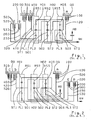
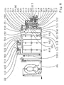
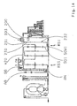
- Fig. 1 and Fig. 2 First, two different component arrangements of a transmission scheme for a multi-stage automatic transmission with non-coaxial arrangement of Antiebs- and output shaft shown, as from the prior art of DE 199 12 480 A1 known. Such arrangements can find application, for example, in a motor vehicle with front-transverse drive.
- the one designated AN Drive shaft of the automatic transmission is operatively connected to a (not shown for simplicity here) drive motor of the automatic transmission, for example via a torque converter or a starting clutch or a torsion damper or a dual mass flywheel or a rigid shaft.
- the AB designated output shaft of the automatic transmission is operatively connected to at least one (for simplicity not shown here) drive axle of the motor vehicle.
- RS1, RS2 and RS3 designate three coupled single planetary gear sets arranged side by side in a transmission housing GG of the automatic transmission. All three planetary gear sets RS1, RS2, RS3 each have a sun gear SO1, SO2 and SO3 each have a ring gear HO1, HO2 and HO3, and a respective web ST1, ST2 and ST3 with planetary gears PL1, PL2 and PL3, each with sun and ring gear of the corresponding wheelset comb. With A to E five switching elements are designated, wherein the first, third and fourth switching element A, C, D are designed as a brake and the second and fifth switching element B, E as a clutch.
- the respective friction linings of the five shift elements A to E are indicated as disk packs 100, 200, 300, 400 and 500 (each with outer and inner disks or steel and lining disks).
- the respective input elements of the five switching elements A to E are denoted by 120, 220, 320, 420 and 520, the respective output elements of the couplings B and E with 230 and 530.
- the kinematic connection of the individual wheelset elements and switching elements relative to each other and relative to drive and output shaft AN, AB has already been described in detail above, as well as the spatial arrangement of these components.
- the lamellae 100 of the (designed as a brake) first switching element A spatially always next to the third planetary gear set RS3 are arranged, that the fins 400 of (designed as a brake) fourth switching element D spatially always next to the first planetary gear RS1 are arranged so that the lamellae 300 (also designed as a brake) third switching element C spatially always next to the lamellae 400 of the fourth switching element D (on the third planetary gearset RS3 side facing away from the brake D) are arranged that the slats 200 of (formed as a clutch) second switching element B and the fins 500 (also designed as a clutch) fifth switching element E are always arranged side by side, and that a first spur gear STR1, which is the output side operatively connected to the output shaft AB, always next to the first switching element A ( on the third planetary gear set RS3 opposite side of the brake A) is arranged.
- a first spur gear STR1 which is the output side operatively connected to the output shaft
- the two side-by-side disk sets 200, 500 of the two clutches B, E are either - as in Fig. 1 shown - arranged axially adjacent to the slats 300 of the brake C, on the side facing away from the third planetary gearset RS3 side of the disk set 300, or - as in Fig. 2 shown - in addition to the spur gear STR1, on the opposite side to the brake A of the spur gear STR1.
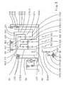
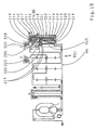
- Fig. 3 now shows a first schematic component arrangement, by way of example for the inventive solution of the problem.
- the multi-stage automatic transmission according to the invention has three coupled individual planetary gear sets RS1, RS2, RS3 arranged coaxially with one another in series, wherein the second planetary gearset RS2 is arranged axially between the first and third planetary gearset RS1, RS3.
- the multi-stage automatic transmission five switching elements A to E on.
- the first, third and fourth switching element A, C, D is in each case as a brake (in the example in each case as a multi-disc brake), the second and fifth switching element B, E each as a clutch (in the example each as a multi-plate clutch).
- a sun gear SO3 of the third planetary gearset RS3 can be fixed via the brake A to a gearbox GG of the multi-stage automatic transmission.
- a drive shaft AN of the multi-stage automatic transmission is constantly connected to a sun gear SO2 of the second planetary gearset RS2.
- the drive shaft AN via the clutch B with a sun gear SO1 of the first planetary gear set RS1 and additionally or alternatively via the clutch E with a web ST1 of the first planetary gearset RS1 connectable.
- the sun gear SO1 of the first planetary gearset RS1 via the brake C and / or the web ST1 of the first planetary gearset RS1 via the brake D to the transmission housing GG can be fixed.
- An output shaft AB of the multi-stage automatic transmission is continuously operatively connected via a spur gear STST with a ring HO1 of the first planetary gearset RS1, said ring gear HO1 is additionally connected in the illustrated exemplary coupling of the wheelset additionally with a web ST3 of the third planetary gearset RS3. Furthermore, a web ST2 of the second planetary gearset RS2 is constantly connected to a ring gear HO3 of the third planetary gearset RS3, and the web ST1 of the first planetary gearset RS1 constantly with a ring gear HO2 of the second planetary gearset RS2.
- the corresponding connecting element between the ring gear HO1 of the first planetary gearset RS1 and the web ST3 of the third planetary gear set RS3 is designed as a cylinder ZYL.
- This cylinder ZYL is on the one hand connected to the ring gear HO1 via a suitable operative connection, for example via a welded joint, and extends in the axial direction from the ring gear HO1 to over the ring gear HO3 over.
- the cylinder ZYL is on the side of the third planetary gearset RS3 facing away from the second planetary gearset RS2 connected via a suitable operative connection with a web plate STB3 of the web ST3, for example via a driving profile.
- the cylinder ZYL thus completely overlaps the second and third planetary gear sets RS2, RS3.
- the first planetary gear set RS1 is completely centered in the axial direction by two shafts, namely a web shaft STW1 designed as a hollow shaft and the drive shaft AN guided radially within this web shaft STW1.
- a web shaft STW1 designed as a hollow shaft and the drive shaft AN guided radially within this web shaft STW1.
- the web shaft STW1 on the second planetary gearset RS2 side facing the first planetary gear set RS1 with a web plate STB12 of the web ST1 of the first planetary gearset RS1, and on the second planetary gearset RS2 side facing away from the first planetary gear set RS1 with an output member 530 of the clutch E.
- the web plate STB12 in turn is connected at its outer diameter with the ring gear HO2 of the second planetary gearset RS2.
- the web shaft STW1 extends radially within a sun shaft SOW1, likewise designed as a hollow shaft.
- This sun wave SOW1 in turn is connected on the one hand to the sun gear SO1 of the first planetary gear set RS1, on the other hand on the side of the first planetary gearset RS1 facing away from the second planetary gearset RS2 with an input element 320 of the brake C and an output element 230, the clutch B.
- the web ST1 passes through the First planetary gearset RS1 in the axial direction and is connected on its side remote from the second planetary gearset RS2 side with an input element 420 of the brake D.
- the drive shaft AN also passes through the second (spatially seen in the middle) planetary gearset RS2 and the third planetary gearset RS3 in the axial direction centric.
- the spur gear STST is axially adjacent to the third planetary gearset RS3 on the side of the web plate STB3 facing away from the second planetary gearset RS2.
- the multi-spur gear STST comprises a first spur gear STR1, which is constantly connected to the web plate STB3 of the third planetary gearset RS3, a second trained as a step gear spur gear STR2, the first gear meshes with the first spur gear STR1, and a third spur gear STR3, with a second toothing of the second spur gear STR2 meshes and is operatively connected via a differential DIFF with the output shaft AB.
- this embodiment of the spur gear STST is to be regarded as exemplary.
- first spur gear STR1 of the spur gear STST Centrally within the first spur gear STR1 of the spur gear STST is designed as a hollow shaft sun shaft SOW3, which is connected on the one hand to the sun gear SO3 of the third planetary gearset RS3, on the other hand on the third planetary gearset RS3 side facing away from the first spur gear STR1 with an input element 120 of the brake A. Radially within this sun shaft SOW3 again runs the drive shaft AN.
- the brake A via which the sun gear SO3 of the third planetary gearset RS3 can be fixed, is spatially arranged on the side facing away from the third planetary gearset RS3 side of the spur gear STST.
- the input member 120 of the brake A formed as an inner disk carrier adjoins axially on one side the first spur gear STR1 of the spur gear STST and on the opposite side axially on a housing wall GW connected rotationally fixed to the gearbox GG.
- housing wall GW and transmission housing GG can also be made in one piece.
- a disk set 100 of the brake A with outer and lining disks is arranged on a large diameter in the region of the inner diameter of the transmission housing GG.
- a driving profile for the outer disks of the disk set 100 can be integrated in a simple manner in the transmission housing GG.
- a separate outer disk carrier may be provided which is connected by suitable means with the gear housing GG or the gear housing fixed housing wall GW form, force or cohesive.
- a not shown here for simplification servo device of the brake A for actuating the slats 100 may be spatially arranged between the housing wall GW and the disk set 100, with a corresponding design of the gear housing but also on the side of the disk set 100, the first spur gear STR1 and the third planetary gear set RS3 faces.
- Fig. 3 In the in Fig. 3 illustrated example penetrates the centrally within the input element 120 of the brake A extending drive shaft AN the housing wall GW and is thus guided on the side of the automatic transmission to the outside, on which the brake A is arranged, ie close to the spur STST.
- the drive shaft AN is connected here by way of example via a torque converter with lockup clutch and torsional damper to a not shown for simplicity drive motor of the automatic transmission.
- the torque converter can be replaced by a suitable other starting element (for example, a clutch) or omitted if at least one of the internal gear shift elements is designed as a starting switching element.
- the two brakes C, D are spatially arranged side by side in a region in the axial direction radially over the planetary gear sets arranged in series.
- a disk pack 400 with outer and lining disks of Brake D is spatially arranged above the third planetary gearset RS3, seen in the axial direction immediately adjacent to the first spur gear STR1 of the spur gear STST, on a large diameter in the region of the inner diameter of the gear housing GG.
- An outer disk carrier for the outer disks of the disk set 400 of the brake D is hereby for example integrated into the transmission housing GG, but can of course also be designed as a separate component, which is then connected via suitable means to the transmission housing.
- a formed as a cylindrical inner disk carrier input element 420 of the brake D extends radially above the cylinder ZYL in the axial direction over all three planetary gear sets RS1, RS2, RS3 away and is connected to a first web plate STB11 of the web ST1 of the first planetary gearset RS1, said first web plate STB11 is arranged on the second planetary gearset RS2 side facing away from the web ST1.
- the inner disk carrier (420) of the brake D thus completely overlaps all three planetary gear sets RS1, RS2, RS3 in the axial direction.
- the spatial position of the disk set 400 of the brake D may also be axially displaced in the direction of the second planetary gearset RS2, so that the inner disk carrier (420) of the brake D then completely overlaps at least the first and second planetary gearset RS1, RS2 in the axial direction ,
- a disk set 300 with outer and lining disks of the brake C is arranged adjacent to the disk set 400 of the brake D, spatially seen approximately above the second planetary gearset RS2, also on a large diameter in the region of the inner diameter of the transmission housing GG.
- An outer disk carrier for the outer disk of the disk set 300 of the brake C is here also exemplified integrated in the transmission housing GG, but can of course also be designed as a separate gearbox fixed component. For manufacturing simplification and cost common parts use the same outer and lining plates can be provided for both brakes C, D.
- An input element 320 of the brake C designed as a cup-shaped inner disk carrier has a cylindrical section 321 and a disk-shaped section 322.
- This cylindrical portion 321 extends radially above a cylindrical portion 421 of the input member 420 of the brake D in the axial direction over the first and second planetary gear set RS1 and RS2.
- the disk-shaped section 322 adjoins the cylindrical section 321 in this area and extends radially inward on the side of the first web plate STB11 facing away from the second planetary gearset RS2 as far as the sun shaft SOW1 to which it is connected.
- the sun shaft SOW1 is in turn connected to the sun gear SO1 of the first planetary gearset RS1.
- the inner disk carrier (320) of the brake C thus completely overlaps the two planetary gear sets RS1, RS2.
- the spatial position of the disk set 300 of the brake C may also be axially displaced, either in the direction of the first planetary gearset RS1, so that the inner disk carrier (320) of the brake C then completely overlaps at least the first planetary gearset RS1 in the axial direction, or but in the direction of the third planetary gearset RS3, so that the inner disc carrier (320) of the brake C then possibly also the third planetary gearset RS3 partially overlaps in the axial direction.
- the other two switching elements B and E are arranged on the side facing away from the second planetary gearset RS2 side of the first planetary gear set RS1, in which Fig. 3 illustrated example on the (not shown) drive motor opposite side of the automatic transmission.
- both clutches B, E are summarized as a pre-assembled assembly, which is arranged adjacent to the first planetary gear set RS1. How out Fig.
- a disk pack 200 is arranged with outer and lining disks of the clutch B in the axial direction radially above a disk set 500 with outer and lining disks of the clutch E, the disk set 200 so spatially seen above the disk set 500th Die Lamellen 300 der Bremse C are thus arranged closer to the fins 200 of the clutch B than the fins 400 of the brake D.
- an input element 520 of the clutch E is arranged, which is designed here as an outer disk carrier and connected to the drive shaft AN.
- An input element 220 of the clutch B which is likewise designed as an outer disk carrier, is connected to the drive shaft AN via the input element 520 of the clutch E.
- Both outer disk carrier (220, 520) can be summarized here advantageously as a common disk carrier, which on the one hand, a manufacturing simplification and on the other hand, a cost common parts use for the outer and lining disks of both clutches B, E allows.
- a formed as an inner disk carrier output element 230 of the clutch B extends - partially axially adjacent to the disk-shaped portion 322 of the inner disk carrier (320) of the brake C - radially inwardly to the sun shaft SOW1 of the first planetary gearset RS1, with which it is connected.
- the person skilled in the art will, as required, carry out the inner disk carrier (230) of the clutch B and the disk-shaped section 322 of the inner disk carrier (320) of the brake C as a common component.
- An output element 530 of the clutch E likewise embodied as an inner disk carrier, extends axially inward between the disk-shaped inner disk carrier (230) of the clutch B and the disk-shaped section of the outer disk carrier (520) of the clutch E - radially inwardly to the web shaft STW1 of the first planetary gearset RS1 he is connected.
- this web shaft STW1 passes through the sun shaft SOW1 centrically and is connected on the side of the first planetary gearset RS1 adjacent to the second planetary gearset RS2 both to the web ST1 of the first planetary gearset RS1 and to the ring gear HO2 of the second planetary gearset RS2.
- Fig. 3 shown component assembly is a spatially seen a very compact, construction length-saving gear assembly achieved.
- the lamellae 200 of the thermally highly loaded clutch B are arranged on an advantageously large diameter, as are the lamellae 400 of the static of all five switching elements most heavily loaded brake D.
- E the same Lamella types or the same slat sizes are used.
- the expert is the drive motor depending on the application optionally as in Fig. 3 arranged on the front side of the automatic transmission, on which the brake A or the spur gear is arranged, or on the opposite end face of the automatic transmission, on which the assembly with the two clutches B, E is arranged.
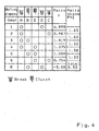
- Fig. 4 shows a circuit diagram with the associated gear jumps and the overall ratio of the automatic transmission according to Fig. 3 ,
- each of two of the five switching elements A to E six forward gears are switchable group circuit, so such that to switch from one gear to the next higher or next lower gear from the currently operated switching elements only one switching element open and another switching element closed becomes.
- the brakes A and D are closed
- the brakes A and C are closed
- the brakes A and C in the third gear “3” brake A and clutch B
- clutch E in the fifth gear “5" the clutches B and E, and in the sixth gear “6” brake C and clutch E.
- a reverse gear "R” clutch B and brake D are closed.
- the individual gear steps allow a good drivability, with advantageously high overall ratio (spread) of the automatic transmission.
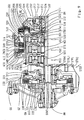
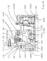
- Fig. 5 shows a detail of the first component assembly according to Fig. 3 , now supplemented by radial shaft and component bearings and servos of the five switching elements A to E.
- the kinematic coupling of the three individual planetary gear sets RS1, RS2, RS3 and the five switching elements A to E and the input and output shafts AN, AB corresponds to the in Fig. 3 illustrated transmission scheme.
- the spatial arrangement of the planetary gear sets RS1, RS2, RS3 and switching elements A to E relative to each other within the transmission housing GG was virtually unchanged from Fig. 3 accepted.
- the brake A (as the first switching element of the automatic transmission) is arranged here on the drive motor side of the automatic transmission.
- the brake A directly adjoins the housing wall GW, which - analogous to Fig. 3 - Which forms the (not shown) drive motor or here exemplified as Trilokwandler gearbox-external starting element of the automatic transmission facing outer wall of the automatic transmission.
- the housing wall GW may be formed as part of the transmission housing GG or as a separate component, which is then rotationally connected by suitable means with the transmission housing GG.
- An output element 130 of the brake A designed as an outer disk carrier is advantageously integrated into the housing wall GW in production engineering terms. Accordingly, the input element 120 of the brake A is designed as an inner disk carrier.
- this largely disc-shaped inner disk carrier (120) extending from its lamella driving profile adjacent to the housing wall GW radially inwardly to the sun shaft SOW3, with which it is connected.
- this sun wave SOW3 is provided as an operative connection between the input element (inner disk carrier) 120 of the brake A and the sun gear SO3 of the third planetary gearset RS3 and designed as a hollow shaft, within which the drive shaft AN runs.
- the designated as 110 servo device of the brake A is shown in simplified form and arranged on the side of the disk set 100 of the brake A, the the first spur gear STR1 and the third planetary gear set RS3 operatively connected to the output shaft AB.
- the servo device 110 comprises - as usual - a piston which is axially displaceably mounted in a corresponding piston or pressure chamber, and a return element for this piston.
- the piston When pressure is applied to the piston chamber via a corresponding pressure medium supply, the piston then actuates the lamellae 100 of the brake A against a restoring force of the return element axially in the direction of the housing wall GW.
- the piston or pressure chamber of the servo device 110 is integrated in the housing wall GW.
- Fig. 3 is spatially axially between the brake A and the (drive motor-facing) third planetary gear set RS3, the first spur gear STR1 of the spur gear not shown here, which establishes the operative connection between the output of the coupled planetary gear and the output shaft of the automatic transmission arranged.
- This spur gear STR1 is mounted on a housing intermediate wall GZ, which is rotationally connected to the transmission housing GG and extending radially inwardly, starting from the inner diameter of the transmission housing GG. Spatially, this housing intermediate wall GZ is arranged, for example, axially between the spur gear STR1 and the third planetary gearset RS3, axially directly adjacent to the spur gear STR1.
- the spur gear STR1 On its side lying opposite the housing intermediate wall GZ, the spur gear STR1 directly adjoins a disk-shaped section 122 of the inner disk carrier (120) of the brake A.
- the sun shaft SOW3 provided as an operative connection between the sun gear SO3 of the third planetary gear set RS3 and the input element (inner disk carrier) 120 of the brake A thus penetrates the housing intermediate wall GZ centrally.
- the housing intermediate wall GZ, on which the first spur gear STR1 is mounted of course, be arranged on the planetary gearset RS3 side facing away from the spur gear STR1, spatially seen so between the inner disc carrier (120) of the brake A and the spur gear STR1.
- the housing intermediate wall GZ may also be formed as part of the transmission housing.
- the disk sets 300, 400 of the two brakes C, D directly adjoin one another axially.
- the servo device 410 of the brake D is arranged on the side of the disk set 400 of the brake D facing the spur gear STR1 or the brake A or the housing intermediate wall GZ and actuates these disks 400 axially in the direction of the brake C.
- the servo 310 of the brake C is arranged on the side facing away from the brake D side of the disk set 300 of the brake C and actuates these blades 300 axially in the direction of the brake D.
- the actuating direction of both servos 310, 410 is thus opposite to each other.
- the clutches B and E are both arranged on the opposite side of the first planetary gearset RS1 to the second planetary gearset RS2 and form a preassemblable subassembly adjacent to the first planetary gearset RS1.
- the disk set 200 of the clutch B is arranged, viewed in the axial direction, at least predominantly radially above the disk set 500 of the clutch E.
- the advantageously large diameter of the slats 200 contributes to the conceptually comparatively high thermal load of the clutch B bill.
- a common plate carrier ZYLBE is provided as their input elements 220, 520, which is designed for the clutch E as an outer disk carrier and for the clutch B as an inner disk carrier.
- this plate carrier ZYLBE has a hub 523 which is connected to the drive shaft AN and is mounted on a gearbox fixed hub GN. From the selected nomenclature it can be seen that this hub 523 is to be assigned to the input element (520) of the clutch E.
- the gearbox fixed hub GN is a cylindrical projection of a (in Fig. 5 for simplicity not shown) outer wall of the gear housing GG, which extends axially in the direction of the first planetary gear set RS1 out.
- the hub GN also in a housing cover be integrated, which is then rotationally connected to the transmission housing via suitable means.
- the drive shaft AN itself is also mounted on the hub GN in the example shown.
- the disk carrier ZYLBE common to the clutches B, E has geometrically different sections 521, 522, 524, 221 and 222, which from the nomenclature either the input element (520) of the clutch E or the input element (220) of the clutch B are assigned.
- the disk-shaped portion 522 is approximately centered hub in the axial direction with the hub 523 and extends, starting from the outer diameter of the hub 523, radially outward.
- the cylindrical portion 521 adjoins the disk-shaped portion 522 and extends axially in the direction of the planetary gearset RS1 to above the disk set 500 of the clutch E.
- the cylindrical portion 521 has a suitable entrainment profile for receiving the outer disk of the disk set 500 of the clutch E.
- the cylindrical portion 521 joins the (the input element (220) of the clutch B attributable) disk-shaped portion 222 at and extends radially outward to a diameter approximately equal to the outer diameter of the disk set 200 of the (radially outer) clutch B.
- the cylindrical portion 221 joins the disk-shaped portion 222 and extends axially in the direction of the planetary gear set RS1 to beyond the disk set 200 of the clutch B.
- the cylindrical portion 221 has a suitable driving profile for receiving the outer disk of the disk set 200 of the clutch B.
- the input element 220 of the clutch B is therefore (as in Fig. 3 ) is connected via the input element 520 of the clutch E to the drive shaft AN.
- the sections 521 and 522 of the disc carrier B, E common disc carrier ZYLBE form a clutch space, within which not only the disc pack 500 of the clutch E is arranged, but also a designated 510 servo means for actuating the fins 500 of the clutch E.
- This servo 510 is thus disposed on the side of the disk-shaped portion 522 facing the first planetary gear set RS1.
- the first cylindrical portion 521, the disc-shaped portion 522 and the hub 523 of the disc carrier ZYLBE (or the input member (520) of the clutch E) form a piston or pressure chamber 511 in which a piston 514 of the servo 510 is arranged axially displaceable ,
- the piston 514 actuates the disks 500 of the clutch E axially in the direction of the planetary gear set RS1 against a restoring force of a restoring element 513 of the servo device 510, exemplified here as a plate spring.
- the pressure medium supply to the pressure chamber 511 takes place via a Pressure medium supply 518, which extends partially within the hub 523 and partially within the housing fixed hub GN.
- the servo 510 also has a pressure compensation chamber 512 which is disposed on the pressure chamber 511 opposite side of the piston 514, that is arranged closer to the planetary RS1 than the pressure chamber 511.
- This pressure compensation chamber 512 is formed by the piston 514 and a baffle plate 515 and is geometrically preferably designed such that an at least substantially complete dynamic pressure compensation is achieved.
- the pressure compensation chamber 512 is filled via a lubricant supply 519 without pressure with lubricant, said lubricant supply 519 extends partially within the hub 523 and partially within the drive shaft AN.
- the servo of the clutch B is designated 210.
- a piston 211 of this servo 210 is disposed on the side of the disk-shaped portion 522 of the disk carrier ZYLBE, which faces the pressure space 511 of the clutch E.
- the pressure chamber 211 is formed by the hub 523, the disk-shaped portion 522 and a second cylindrical portion 524 of the disk carrier ZYLBE (or the input member (520) of the clutch E), said second cylindrical portion 524 axially into the pressure chamber 511 of the clutch E opposite direction extends.
- a piston 214 of the servo device 210 is arranged axially displaceable.
- this piston 214 actuates the disks 200 of the clutch B axially in the opposite direction to the first planetary gearset RS1, against a restoring force of a restoring element 213 of the servo device 210, exemplified here as a disk spring.
- the piston 214 overlaps the clutch E for both clutches B common plate carrier ZYLBE - in particular its sections 522, 524, 521 and 221 - in the axial direction radially completely.
- an actuating punch 216 of the piston 214 acts from the side of the disk pack 200 on this disk set 200, which is opposite to the pressure chamber 211.
- the geometric contour of the piston 214 adapted to the plate carrier sections 522, 524, 521 and 221 formed lateral surface of the plate carrier ZYLBE.
- the pressure medium supply to the pressure chamber 211 takes place via a pressure medium supply 218, which extends partially within the hub 523 and partially within the housing-fixed hub GN.
- the servo device 210 of the clutch B also has a pressure equalization chamber 212 on, which is arranged on the pressure chamber 211 opposite side of the piston 214.
- This pressure compensation chamber 212 is formed by a baffle plate 215 and by a section of the piston 214 arranged radially below the plate carrier section 524.
- the pressure compensation chamber 212 is geometrically designed such that an at least substantially complete dynamic pressure equalization is achieved.
- the pressure compensation chamber 212 is filled via a lubricant supply 219 without pressure with lubricant, said lubricant supply 219 extends partially within the hub 523 and partially within the housing fixed hub GN.
- the disk-shaped sections 522 thus essentially forms the radially directed lateral surface of the disk carrier ZYLBE, on whose side facing the planetary gearset RS1 the pressure chamber 511 of the servo device of the clutch E is arranged, and on whose side facing away from the planetary gear set RS1 the pressure chamber 211 of the servo device of the clutch B. is arranged.
- This region of the lateral surface of the plate carrier ZYLBE thus separates the two pressure chambers 211 and 511 from each other.
- the pressure equalization chambers 212 and 512 of the servos of the clutches B and E, which are provided for the dynamic pressure equalization of the respective rotating pressure chamber 211 and 511 respectively, are arranged on the side of the respective pressure chamber 211 or 511, which faces away from this region of the lateral surface of the disk carrier ZYLBE.
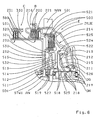
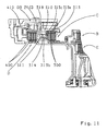
- Fig. 6 shows a sectional gear section with an exemplary detailed construction for the assembly with the two clutches B, E.
- Clutches B and E form a preassembled subassembly which comprises the disk packs 200, 500 and the respective servo device of both clutches B, E and a disk carrier ZYLBE common to both clutches B, E.
- the plate carrier ZYLBE is designed as an outer plate carrier for both couplings B, E, in the form of a (in the direction of (in FIG Fig. 6 not shown) adjacent planetary gear sets open pot.
- the plate carrier ZYLBE is subdivided into differently shaped sections 221, 521, 525, 524, 522 and 523.
- the two cylindrical sections 521, 524 and the two disk-shaped sections 525, 522 and the hub 523 form the input element of the clutch E, which is connected to the drive shaft AN.
- the cylindrical portion 221 forms the input member of the clutch B, which is connected via the input member of the clutch E to the drive shaft AN.
- corresponding driving profiles are provided for receiving the outer disks of the disk sets 200 and 500.
- Fig. 5 is the disk set 200 of the clutch B arranged on a larger diameter than the disk set 500 of the clutch E.
- the disk packs 200 and 500 of both clutches B, E have an axial offset from one another.
- the friction surface inner diameter of the lining plates of the disk set 200 is greater than the friction surface outer diameter of the lining disks of the disk set 500
- the pitch circle diameter of the lamella driving profile of the outer disk of the disk set 500 is greater than the pitch diameter of the lamella driving profile of the lining disks of the disk set 200th ,
- the diameter of the disk set 200 of the clutch B is chosen so that the disk set 200 seen in the axial direction radially above the adjacent to this clutch assembly first planetary gear set (of which for simplicity in Fig. 5 only its sun gear SO1 is shown) could be arranged.
- the disk set 500 of the clutch E directly adjacent axially to the first planetary gear set (RS1) spatially in a range approximately to the diameter range of (not closer shown) ring gear of the first planetary gear set corresponds.
- Such a component nesting has advantages on the one hand with regard to the transmission length, on the other hand also in terms of the outer diameter of the transmission housing in a gear housing section, for which in a vehicle with built-in transverse to the direction drive motor due to the body structure is known only a very limited installation space available.
- the transition between the cylindrical portion 221 of the (outer) disc carrier ZYLBE to be assigned to the input member of the clutch B and the first cylindrical portion 521 of the disc carrier ZYLBE (to be assigned to the input member of the clutch E) also has a diameter offset and a step, respectively.
- the slats 200 of the clutch B are supported axially in their ("pulled") operation.
- a locking ring 501 is provided which engages in the Lamellenmit Spotify of the cylindrical portion 521 and is secured by a suitable device axially to the portion 521 of the disc carrier ZYLBE.
- Such axial securing may be, for example, a groove which is milled radially into the driving profile of the disk carrier ZYLBE at the corresponding axial position in the area above the securing ring 501 or radially pressed into the driving profile of the disk carrier ZYLBE as material settings (material indentations).
- Such an axial securing are a subsequently performed caulking of the locking ring 501 on the plate carrier ZYLBE, or subsequently on the side facing away from the plate pack 500 side of the locking ring 501 axially adjacent to this locking ring 501 radially into the driving profile of the plate carrier ZYLBE introduced material settings (material Indentations), or as radial pinning of the locking ring 501 on the plate carrier ZYLBE.
- the first disk-shaped portion 522 extends radially outward approximately at the center of the hub.
- Designated at 526 is a first cylindrical portion of the hub 523 which extends axially on the side of the disc-shaped portion 522 facing away from the planetary gearset RS1.
- Designated at 527 is a second cylindrical portion of the hub 523 which extends axially on the side of the disc-shaped portion 522 facing the planetary gearset RS1.
- a pressure chamber is arranged in each case.
- a second cylindrical section 524 adjoins the first disk-shaped section 522 and extends axially in a direction opposite to the planetary gear set RS1, approximately as far as the first cylindrical section 526 of the hub 523 extends.
- a second at least substantially disc-shaped section 525 which extends radially outward to approximately the outer diameter of the disk set 500, up to the first cylindrical section 521 of the input element of the clutch E.
- the disk carrier ZYLBE or the input element of the clutch E with its in the order 521, 525, 524, 522 and 523 adjoining sections has a total meandering structure seen in the radial direction, forming a clutch space, within which the servo device the clutch E and the disk sets 200 and 500 of both clutches B, E are arranged.
- the pressure medium supply 518 to this pressure chamber 511 passes in sections the hub 523 (in the hub portion 527) of the common outer disk carrier of the clutches B, E and in sections through the housing fixed hub GN.
- the pressure compensation chamber 512 formed by the piston 514 and the baffle plate 515 for compensating the dynamic pressure of the rotating pressure chamber 511 is arranged on the side of the piston 514 opposite the pressure chamber 511, ie closer to the first planetary gearset RS1 than the pressure chamber 511.
- the lubricant supply 519 too this pressure equalization chamber 512 extends in sections through the hub 523 (in the hub portion 527) of the common disk carrier ZYLBE of the clutches B, E and in sections by the drive shaft AN.
- the restoring element 513 which is embodied, for example, as a disc spring, is pretensioned between piston 514 and baffle plate 515, the baffle plate 215 being supported axially on the drive shaft AN.
- the piston 214 extends in the axial direction far beyond the disk set 200 of the clutch B, into an area above the first planetary gear set RS1.
- the actuating punch 216 acting on the disk pack 200 is fastened to the piston 214 in the region above the disk set 200 and extends radially inwardly almost to the inside diameter of the disk set 200.
- the pressure medium feed 218 to the pressure chamber 211 of the servo device of the clutch B extends in sections through the hub 523 (in the hub portion 526) of the common disk carrier ZYLBE the clutches B, E and sections through the housing fixed hub GN.
- the servo device of the clutch B has a dynamic pressure compensation.
- the corresponding pressure compensation chamber 212 for compensating the dynamic pressure of the rotating Pressure chamber 211 is spatially disposed below the cylindrical portion 524 of the plate carrier ZYLBE and is formed by the piston 214 and the baffle plate 215.
- the lubricant supply 219 to this pressure compensation chamber 212 extends in sections through the hub 523 (in the hub portion 526) of the plate carrier ZYLBE, in sections the housing-fixed hub GN and in sections by the drive shaft AN.
- the restoring element 213 designed as a disk spring for resetting the piston 214 is arranged outside the pressure compensation chamber 212 and rests against the outer side surface of the piston 214 on the side of the assembly of clutch B and E opposite the planetary gearset RS1. In this case, this plate spring (213) between the outer surface of the piston 214 and a arranged on the outer edge of the first cylindrical hub portion 526 Abstützbund the hub 523 is axially biased.
- the first disk-shaped sections 522 thus essentially forms the radially directed (in this case substantially vertical) lateral surface of the disk carrier ZYLBE, on whose side facing the planetary gear set RS1 the pressure chamber 511 of the servo device of the clutch E is arranged, and on the side facing away from the planetary gearset RS1 side of the pressure chamber 211 of the servo of the clutch B is arranged.
- This region of the lateral surface of the plate carrier ZYLBE thus separates the two pressure chambers 211 and 511 from each other.
- the pressure equalization chambers 212 and 512 of the servos of the clutches B and E which are provided for the dynamic pressure equalization of the respective rotating pressure chamber 211 and 511 respectively, are arranged on the side of the respective pressure chamber 211 or 511, which faces away from this region of the lateral surface of the disk carrier ZYLBE. Both clutches B, E are completely independently operable, the operation of one of these two clutches thus has no effect on the other clutch.
- the hub 523 of the disk carrier ZYLBE is connected in the example shown by a welded connection to the drive shaft AN, spatially in the range of planetary gearset near hub portion 527.
- a welded connection and a releasable connection may be provided, for example, a driving profile.
- the piston 214 of the servo B of the clutch B in its section, which is spatially arranged above the disk set 500 of the clutch E, at its outer diameter has a suitable encoder profile, which via a drive speed sensor NAN for determining the drive shaft Speed (non-contact) is sampled.
- the trained as an inner disk carrier output member 530 of the clutch E has an axially only short cylindrical portion 531, on whose outer diameter a suitable driving profile for receiving the lining disks of the disk set 500 is provided.
- a suitable driving profile for receiving the lining disks of the disk set 500 is provided.
- Trained as an inner disk carrier output element 230 of the clutch B has a cylindrical portion 231, which is arranged in the axial direction next to the disk set 500 of the clutch E and also next to the servo device of the clutch E, seen in the axial direction radially above the (incomplete On the side facing the clutch E of the cylindrical portion 231, a disk-shaped portion 232 of the inner disk carrier (230) of the clutch B connects to the cylindrical Section 231 and extends - axially immediately adjacent to the pressure chamber side facing away from the disk set 500 and the disk-shaped portion 532 of the inner disk carrier (530) of the clutch E - radially inwardly, up to the sun gear SO1 of the first planetary gear set.
- the brake C is arranged next to the disk set 200 of the clutch B, on the opposite side of the clutch E clutch pack 200th From the diameter, the blades 300 of the brake C are at least similar dimensioned as the slats 200 of the clutch B.
- the Inner disk carrier formed input element 320 of the brake C is made together with the inner disk carrier (230) of the clutch B in one piece.
- the cylindrical portion 321 of this input member 320 has at its outer diameter a suitable driving profile for receiving the lining disks of the disk set 300 and immediately connects axially to the cylindrical portion 231 of the output member 230 of the clutch B.
- the lamella driving profiles for the lining disks of both disk sets 300, 200 are identical, whereby the use of identical lining disk types is also possible.
- an output element 330 of the brake C which is designed as a cylindrical outer disk carrier with a corresponding lamella driving profile for the outer disks of the disk set 300 and designed as a separate component.
- a cylinder can for example also record the servo of the brake C and the complete brake D (including their servo and slats) and preassembled as an assembly, which is then inserted into the gear housing and secured against rotation.
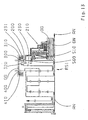
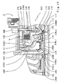
- Fig. 7 now shows a section of a gear section of a practical gear design, based on the gear section according to Fig. 5 , with the essential features of the detailed construction according to Fig. 6 , Relative to the out Fig. 5 known spatial arrangement of the three planetary gear sets RS1, RS2, RS3 and five Druckelmente A to E, the position of the drive motor of the automatic transmission is now mirrored.
- the drive motor operatively connected to the drive shaft AN is thus now arranged on the transmission side, on which also the assembly with the two clutches B and E is arranged.
- the bearing STRL1 of the first spur gear STR1 is exemplified as a stiff tapered roller bearing, with two immediately adjacent tapered roller bearings.
- the bearing inner rings of these two tapered roller bearings are clamped axially on a spur gear hub STRN1 of the spur gear STR1, which extends axially in the direction opposite to the third planetary gear set RS3, via a shaft nut.
- the bearing outer rings of these two tapered roller bearings are each inserted in a bearing bore of the housing intermediate wall GZ and are each supported on an axially between the two tapered roller bearings radially inwardly extending abutment shoulder of the housing intermediate wall GZ.
- the Stirnradnabe STRN1 of the spur gear STR1 passes through the housing intermediate wall GZ so centric.
- the housing intermediate wall GZ simultaneously forms an output element 130 of the brake A, which is designed as an outer disk carrier with a corresponding driving profile for receiving the outer disks of the disk set 100 of the brake A.
- the brake A is seen in the axial direction partially radially over the storage STRL1 of the first spur gear STR1 arranged, in particular the integrated into the housing intermediate wall GZ servo device 110 of the brake A.
- the housing intermediate wall GZ is rotationally connected to the transmission housing GG, a corresponding (usual) screw is in Fig. 7 not shown for simplicity.
- the bearing of the intermediate shaft (STR2) is exemplarily supported by two tapered roller bearings, wherein the first of these tapered roller bearings is spatially arranged in the area above the third planetary gearset RS3, on the side of the first spur gear STR1 facing away from the bearing STRL1 and the brake A, respectively.
- the second of these tapered roller bearings is spatially arranged in the area above the adjacent disk sets 200 and 500 of the clutches B and E, as seen from the direction of the first spur gear STR1 axially before the third spur gear STR3.
- the drive motor-side housing wall GW is designed in two parts in this example, with part of this two-part housing wall GW covering a differential cover and the differential DIFF to the drive motor side.
- a pump and various pressure medium channels are integrated to supply the various transmission components with lubricant and the switching elements with pressure medium.
- the brake A is correspondingly arranged on the end face of the transmission housing GG facing away from the drive motor.
- the brakes C and D form a preassembled assembly, which is inserted as a whole in the transmission housing.
- This assembly comprises the output members 330, 430 of both brakes C and D formed as outer disk carriers, the disk packs 300, 400 of both brakes C and D, and the servos 310, 410 of both brakes C and D.
- the two outer disk carriers 330 and 430 designed as a one-piece cylindrical component, which in Fig. 7 designated ZYLCD, in which also parts of the servo devices 310 and 410 are integrated.
- Such an assembly is for example from the DE 101 31 816 A1 the applicant known.
- the cylinder ZYLCD also forms a bearing seat for the spur gear STR1 near tapered roller bearing of the bearing of the side shaft (STR2).
- Fig. 8 now shows an exemplary second schematic component assembly according to the invention.
- this second component arrangement according to the invention is similar to that in Fig. 5 shown first schematic component arrangement.
- the clutches B and E form a preassembled assembly, which is arranged on the side of the first planetary gear set RS1, which is opposite to the other Planetenrad arrangementsn RS2, RS3.
- the input element 520 of the clutch E and the input element 220 of the clutch B are combined as a common plate carrier ZYLBE, which is connected to the drive shaft AN via suitable means (driving profile, welded joint, one-piece design, ).
- the input element 220 of the clutch B is thus connected unchanged via the input element 520 of the clutch E to the drive shaft AN.
- the common plate carrier ZYLBE forms for the clutch E its outer plate carrier (520) and for the clutch B its inner plate carrier (220).
- the disk packs 200 with outer and lining disks of the clutch B and 500 with outer and lining disks of the clutch E are spatially arranged at least substantially one above the other, wherein the disk set 200 of the clutch B - Fig. 5 -
- the outer of the two plate packs and both disk sets 200, 500 are arranged axially adjacent to the first planetary gear set RS1.
- the geometrically differently shaped sections 523, 522, 525, 521 and 524 of the clutch carrier B and E common disk carrier ZYLBE the input element 520 of the clutch E are assigned.
- the hub 523 is connected to the drive shaft AN and in turn has two cylindrical hub portions 527 and 526 of axial extent. These two hub portions 527 and 526 are spatially separated from each other by the first disc-shaped portion 522. Starting from the outer diameter of the hub 523, this first disk-shaped portion 522 extends radially outward approximately centrally of the hub and merges into the second disk-shaped portion 525, which then continues to extend radially outward.
- the hub portion 527 is disposed on the side of the disc-shaped portion 522 facing the planetary gear set RS1. Accordingly, the hub portion 526 is disposed on the side of the disc-shaped portion 522 facing away from the planetary gear set RS1.
- the first cylindrical portion 521 connects and extends axially in the direction of the planetary gear set RS1, up to the disc pack 500 of the clutch E.
- the first cylindrical portion 521 has a suitable driving profile for receiving the
- the first cylindrical section 521 has at its outer diameter a suitable carrier profile for receiving the lining disks (inner disks) of the disk set 200 of the clutch B.
- the outer diameter of the first disk-shaped portion 522 is also followed by the second cylindrical portion 524 and extends radially above the hub portion 526 axially in the direction opposite to the planetary gearset RS1 or in the disk packs 500, 200 opposite direction.
- the common for both clutches B, E disc carrier ZYLBE thus forms a coupling space, within which the clutch E is arranged with its disc pack 500 and its servo 510.
- the complete servo device 510 of the clutch E (including its pressure chamber 511, its piston 514, its pressure compensation chamber 512, its restoring element 513 and its baffle plate 515) spatially disposed at least substantially radially above the hub portion 527.
- the pressure space 511 is formed by the piston 514, as well as the cylindrical hub portion 527 and the disc-shaped portion 522 and parts of the cylindrical portion 521 of the disc carrier ZYLBE.
- the pressure compensation chamber 512 formed by the piston 514 and the baffle plate 515 for compensating the dynamic pressure of the rotating pressure chamber 511 is arranged on the side of the piston 514 opposite the pressure chamber 511, ie closer to the first planetary gearset RS1 than the pressure chamber 511.
- the exemplified as a plate spring return element 513 is biased between the piston 514 and baffle plate 515, wherein the baffle plate 515 is axially supported on the hub 523 of the plate carrier ZYLBE.
- the pressure chamber 211, the pressure compensation chamber 212 and the return element 213 of the servo device 210 of the clutch B are arranged spatially radially above the hub portion 526.
- the pressure compensation chamber 212 directly adjoins the first disk-shaped portion 522 of the disk carrier ZYLBE and is formed by this disk-shaped portion 522, the cylindrical hub portion 526, the cylindrical portion 524 and the piston 214.
- the piston 214 is thus through the pressure compensation chamber 212 separated from the lateral surface of the plate carrier ZYLBE.
- the piston 214 is sealed against the second cylindrical portion 524 axially displaceable (at least substantially lubricant-tight) sealed, preferably on Inner diameter of the second cylindrical portion 524.
- the piston 214 includes the second cylindrical portion 524 in the axial and radial directions.
- the restoring element 213 which is embodied here as a helical spring packet and prestressed between the disk carrier section 522 and piston 214, is arranged, so that the piston 214 has a generally radially directed meander-shaped structure in the region of the pressure compensation chamber 212.
- Geometrically seen the piston 214 in the further course of the outer contour of the common for both clutches plate carrier ZYLBE in the axial and radial directions at least largely and ultimately extends axially up to the plate set 200 of the clutch B.
- the pressure chamber 211 for actuating the piston 214 is correspondingly arranged on the pressure compensation chamber 212 opposite side of the piston 214.
- the pressure chamber 211 is formed by the piston 214, the cylindrical hub portion 526 and by a cylindrical support disk 217.
- This support disk 217 has a disk-shaped portion whose inner diameter is pushed onto the hub portion 526 of the hub 523, axially in the region of the axially outer (non-wheel ) Edge of the hub portion 526 is secured to the hub 523 and in this case also sealed to the hub 523 (fluid-tight).
- the outer diameter of the disk-shaped portion of the support disk 217 is followed by a cylindrical portion which extends axially in the direction of the pressure compensation chamber 212.
- the piston 214 is sealed relative to this cylindrical portion of the support plate 217 and against the cylindrical hub portion 526 axially displaceable (fluid-tight).
- the pressure medium supply to the pressure chamber 211 is again denoted by 218, the lubricant supply to the pressure compensation chamber 212 with 219.
- the radial extent of the pressure compensation chamber 212 so the diameter of the second cylindrical portion 524 is tuned to the geometry of the pressure chamber 211, preferably such that at least a substantial compensation of the rotational pressure component of the clutch pressure of the clutch B is achieved.
- the pressure chamber 511 of the servo device 510 of the clutch E and the pressure equalization chamber 212 (provided for the dynamic pressure chamber 211) of the servo device 210 of the clutch B directly adjoin the lateral surface (sections 522 and 525) of both clutches B and E. common plate carrier ZYLBE.
- the pressure chamber 211 of the servo device 210 of the clutch B is correspondingly arranged on the side of the pressure compensation chamber 212 of the servo device 210 of the clutch B which lies opposite this disk carrier jacket surface (sections 522 and 525).
- pressure compensation chamber 512 of the servo device 510 of the clutch E is correspondingly arranged on the said plate carrier shell surface (sections 522 and 525) opposite side of the pressure chamber 511 of the servo device 510 of the clutch E.
- the output element 530 of the clutch E is designed as an axially narrow inner disk carrier, which, starting from the inner diameter of the disk set 500, axially adjacent to the servo 510 of the clutch E and the pressure compensation chamber 512, radially inwardly extends to the web shaft STW1, with which he connected is.
- the web shaft STW1 is mounted on the drive shaft AN, centrally penetrates the sun gear SO1 of the first planetary gear set RS1 and establishes the kinematic connection between the inner disk carrier (530) of the clutch E and the other wheelset elements according to the power flow scheme.
- the output member 230 of the clutch B is now formed as an outer disk carrier, with a cylindrical portion 231, at the inner diameter of a suitable driving profile for the outer disk of the disk set 200 of the clutch is provided, and with a disc-shaped portion 232, located on the operating side of the disk set 200 facing away from the cylindrical portion 231 connects to this portion 231 and extends radially inwardly, up to the sun gear SO1 of the first planetary gear set RS1, with which it is connected.
- the input element 320 of the brake C is formed as a cylindrical inner disk carrier, which extends in the axial direction seen radially above the second and first planetary gearset RS2, RS1 and thereby completely overlaps the first planetary gearset RS1.
- the cylindrical portion 321 of the inner disk carrier (320) of the brake C abuts on the outer disk carrier (230) of the clutch B, here by way of example on its cylindrical portion 231, and is connected thereto by suitable means (for example, or cohesively).
- cylindrical portion 321 of the inner disc carrier (320) of the brake C (or the entire inner disc carrier of the brake C) and the cylindrical portion 231 of the outer disc carrier (230) of the clutch B are made in one piece.
- the first spur gear STR1 is mounted, for example, directly on an inner wall of the transmission housing GG, which extends radially into the interior of the transmission.
- This inner wall forms so to speak the in Fig. 5 shown housing intermediate wall, but now as a solid gear housing section.
- the two brakes C, D spatially seen in a range over the adjacent planetary gear sets RS1, RS2, RS3 arranged, the brake D predominantly on the third planetary gear set RS3 and the brake C predominantly on the (middle) second planetary gear set RS2.
- Fig. 5 are the two brakes C, D spatially seen in a range over the adjacent planetary gear sets RS1, RS2, RS3 arranged, the brake D predominantly on the third planetary gear set RS3 and the brake C predominantly on the (middle) second planetary gear set RS2.
- Fig. 5 are the two brakes C, D spatially seen in a range over the adjacent planetary gear sets RS1, RS2, RS3 arranged, the brake D
- Fig. 9 now shows a section of a gear section of a practical gear design, based on the gear section according to Fig. 8 ,
- the design of the module with the two clutches B and E corresponds to in Fig. 8 proposed arrangement, so that here on a detailed description of the (provided with the same reference numerals) individual elements of this assembly can be largely dispensed with.
- plate carrier ZYLBE is still pointed to the manufacturing technology and cost favorable embodiment of the disk carrier ZYLBE shown here.
- the plate carrier ZYLBE is designed as a two-part construction.
- the first member of the disc carrier ZYLBE is a cast or forged part or rotating member and includes the disc carrier hub 523, the first disc-shaped portion 522, and the second cylindrical portion 524 of the disc carrier ZYLBE.
- the second component of the disc carrier ZYLBE is a sheet metal forming part and includes the second (approximately) disc-shaped portion 525 and the first cylindrical portion 521 of the disc carrier ZYLBE. Both components of the plate carrier ZYLBE are connected to each other, welded here by way of example.
- the lamellar engagement profile for the lining disks of the (outer) disk set 200 of the clutch B and the driving profile for the outer disks of the (inner) disk set 500 of the clutch E can be made in one operation in an advantageous manner, with correspondingly matched Driving profiles of the affected lamellae.
- two retaining rings 201 and 501 are additionally shown.
- the circlip 201 serves as an axial abutment surface for the disk set 200 of the clutch B, against which this disk set 200 is supported when the pressure chamber 211 of the servo device 210 is pressurized.
- the securing ring 501 serves as an axial contact surface for the disk set 500 of the clutch E, against which this disk set 500 is supported when the pressure chamber 511 of the servo device 510 is pressurized.
- Both circlips 201 and 501 are axially fixed by suitable means on the plate carrier ZYLBE.
- the retaining rings 201 and 501 are used for this purpose in correspondingly shaped grooves of the disk carrier ZYLBE.
- the brakes C and D form a preassembled assembly, which is inserted as a whole in the transmission housing.
- This assembly comprises the output members 330, 430 of both brakes C and D formed as outer disk carriers, the disk packs 300, 400 of both brakes C and D, and the servos 310, 410 of both brakes C and D.
- the two outer disk carriers 330 and 430 designed as a one-piece cylindrical component ZYLCD, in which also parts of the servo devices 310 and 410 are integrated.
- the two disk sets 300, 400 are axially separated from one another by an approximately cylinder-center contact shoulder of the common outer disk carrier ZYLCD.
- the pistons 314 and 414 of the servo devices 310, 410 are each arranged on the outer end face of the respective disk pack 300 or 400.
- the restoring elements 313 and 413 of the servo devices 310, 410 are each arranged spatially radially above the respective disk packs 300 and 400, respectively.
- the actuation direction of both servos 310, 410 when closing the respective brake C or D as a result of pressurization of the respective pressure chamber 311 or 411 of the servo 310 or 410 are thus directed opposite to each other.
- Such an assembly is from the DE 101 31 816 A1 the applicant known.
- the brake C is arranged closer to the assembly with the two clutches B and E than the brake D.
- the brake C is arranged in a region radially above the first and second (middle) planetary gearset RS1, RS2, the brake D in a region radially above the second (middle) and third planetary gearset RS2, RS3.
- the lamellae 200, 300 and 400 of clutch B, brake C and brake D at least approximately the same diameter.
- the output member (outer disk carrier) 230 of the clutch B is exemplified as a cylindrical sheet metal construction, the smallest diameter of its disk-shaped portion 232 with the sun gear SO1 of the first planetary gearset RS1 connected (here welded example) is.
- the input element 320 (inner disc carrier) of the brake C is exemplified as an annular sheet metal construction, the - spatially approximately radially over the clutch E facing web plate STB11 of the web of the first planetary gear set RS1 and approximately on the diameter of the slats 200 of the clutch B - to the disc-shaped portion 232 of the outer disk carrier (230) of the clutch B (here riveted example) is.
- the input element (inner disk carrier) 420 of the brake D is also exemplified as a cylindrical sheet metal construction, the radially overlaps the first and second planetary gearset RS1, RS2 seen in the axial direction while partially radially below the inner disk carrier (320) of the brake C and extends at its smallest diameter at the outer diameter of the couplings B, E facing web plate STB11 of the first planetary gearset RS1 is connected to this web plate STB11, welded here exemplified on a diameter which is slightly smaller than the pitch circle diameter of the ring gear HO1 of the first planetary gearset RS1.
- a parking lock gear PSR drawn which is seen in the axial direction radially over the second planetary gearset RS2 opposite web plate STB3 of the web ST3 of the third planetary gearset RS3 is arranged.
- web plate STB3 and parking lock PSR are made in one piece.
- a circumferential tooth profile is provided on the outer diameter of the parking brake gear PSR, in which a (not shown for simplicity here) parking pawl can intervene to block the transmission output.
- the cylinder ZYL which produces the connection between the web plate STB3 of the third planetary gear set RS3 and the ring gear HO1 of the first planetary gearset RS1 according to the kinematic coupling of the individual wheelsets, passes through corresponding axial recesses of the web plate STB3 below the tooth profile of the parking brake gear PSR and is on the wheel set facing away Side axially secured.
- the first spur gear STR1 of this spur gear STST is here spatially arranged axially between the third planetary gearset RS3 and the brake A, axially adjacent to the sun gear SO3 and the (on the side facing away from the middle planetary gearset RS2 side of the third planetary gearset RS3 arranged) web plate STB3 of the third planetary gearset RS3, on the other hand axially adjacent to the inner disk carrier (120) of the brake A.
- the corresponding carrier profile is spatially arranged on the inner diameter of the web plate STB3.
- a thrust bearing is arranged between the spur gear STR1 and the sun gear SO3.
- the bearing of the first spur gear STR1 which is embodied as a stiff taper roller bearing by way of example, is denoted by STRL1 and comprises by way of example two conical roller bearings directly adjacent to each other.
- the bearing inner rings of these two tapered roller bearings are axially clamped on a Stirnradnabe STRN1 of the first spur gear STR1, which extends axially in the direction opposite to the third planetary gear set RS3 direction, via a shaft nut.
- the bearing outer rings of these two tapered roller bearings are inserted into a respective bearing bore of a bearing plate LAG and are each supported on an axially between the two tapered roller bearings radially inwardly extending abutment shoulder of the bearing plate LAG.
- a tapered roller composite bearing can be provided or a deep groove ball bearing.
- the bearing plate LAG itself is inserted into a corresponding bearing plate bore of the housing intermediate wall GZ and screwed to this intermediate housing wall GZ.
- the Stirnradnabe STRN1 of the spur gear STR1 thus passes through the bearing plate LAG and the housing intermediate wall GZ, both of which are arranged on the side facing away from the Radsatz the first spur gear STR1, centric.
- the housing intermediate wall GZ in turn is screwed (on the wheel set side facing away from the first spur gear STR1) in the region of its outer diameter to the transmission housing GG.
- the housing wall GW is axially adjacent to the housing intermediate wall GZ and is likewise connected thereto screwed.
- the housing wall GW in turn forms in the in Fig. 9 illustrated example, the outer wall of the gear housing GG, which is the operatively connected to the drive shaft AN (not shown here) drive motor of the automatic transmission faces.
- the assembly with the two clutches B and E is thus arranged on the drive motor side facing away from the transmission side.
- the housing wall GW is at the same time a pump housing of an oil pump of the automatic transmission for supplying pressure medium to the switching elements and for supplying lubricant to the various switching elements, toothings and bearings. Accordingly, different channels for pressure and lubricant guidance are integrated both in the housing wall GW and in the housing intermediate wall GZ.
- the brake A is disposed immediately adjacent to the housing wall GW, axially between the housing wall GW (pump housing) and bearing plate LAG.
- designed as an outer disk carrier output element 130 of the brake A is integrated into the housing intermediate wall GZ.
- the housing intermediate wall GZ on its pump side to a sufficiently large axial bore on which inner diameter a suitable driving profile for receiving the outer disk of the disk set 100 of the brake A is provided.
- the outer diameter of the disk set 100 of the brake A is slightly larger than the outer diameter of the bearing plate LAG.
- the disk set 100 of the brake A is axially adjacent directly to the housing wall GW (or to the pump housing).
- the radially outer region of the bearing plate LAG axially adjoins the disk pack 100.
- the servo device 110 of the brake A is integrated in the bearing plate LAG. Accordingly, the bearing plate LAG has a piston or pressure chamber 111, within which a piston 114 of this servo device 110 is arranged to be axially displaceable.
- the piston 114 When pressure is applied to this pressure chamber 111 (via non-rotating pressure medium channels which are not shown here for the sake of simplicity), the piston 114 actuates the disk set 100 of the brake A axially in the direction of the housing wall GW, against a restoring force of a restoring element 113, which is exemplified here as a disk spring axially supported on a correspondingly formed collar of the bearing plate LAG.
- the servo device 110 of the brake A is thus spatially arranged largely above the bearing STRL1 of the first spur gear STR1 of the spur gear STST.
- the bearing plate LAG is inserted from the slat side of the brake A into the housing intermediate wall GZ.
- the screwing of the bearing plate LAG to the housing intermediate wall GZ also takes place from the lamella side of the brake A.
- 110 are provided in the pressure chamber 111 of the servo device 110 of the brake A axially opposite to the piston 114 of the servo device directed Aussenkungen distributed on the periphery of the pressure chamber 111 and record the screw heads of Lagerplattenverschraubung.
- the housing intermediate wall GZ, the bearing plate LAG with spur STRL1 and the first spur gear STR1, and the brake A with servo 110 and disc pack 100 form a preassembled module that can be used as a whole in the transmission housing GG.
- the housing intermediate wall GZ is first inserted into the transmission housing GG, then with the Stirnradlagerung STRL1 and the first spur gear STR1 preassembled bearing plate LAG in the housing intermediate wall GZ is used, then the Servo 110 of the brake A is mounted on the bearing plate LAG, and finally the disk set 100 of the brake A is inserted into the housing intermediate wall GZ.
- the input element 120 of the brake A is an inner plate carrier and exemplified as a cylindrical sheet or forged construction.
- This axially short-built inner disk carrier (120) has a cylindrical portion 121, on the outer diameter of a driving profile is provided for receiving the lining disks of the disk set 100 of the brake A, and below the inner diameter of the restoring element 113 of the servo device of the brake A is arranged.
- a disk-shaped portion 122 of the inner disk carrier (120) of the brake A connects to the cylindrical portion 121 and extends radially inwardly to a hub-shaped portion of the sun shaft SOW1, is welded to ,
- the sun shaft SOW3 in turn is positively connected to the sun gear SO3 of the third planetary gearset RS3 via a suitable driving profile, so that the sun shaft SOW3 can also be interpreted as a hub of the inner disk carrier (120) of the brake A.
- the drive shaft AN runs radially inside the sun shaft SOW3 and penetrates the housing wall GW centrally.
- the second spur gear STR2 of the spur gear forms an intermediate gear between the first spur gear STR1 and the third spur gear of the spur gear STST, not shown here.
- the second spur gear STR2 is designed as a step gear, with a first toothing, which meshes with the teeth of the first spur gear STR1, and with a second toothing, the meshes with the teeth of the third spur gear.
- the second toothing of the second spur gear STR2 is close to the drive motor arranged, seen in the axial direction in a region radially above the brake A.
- FIG. 10 shows a second exemplary detailed construction of the transmission according to the invention according to Fig. 8 respectively.
- Fig. 9 explained. It shows Fig. 10 a sectional gear section in the region of the first planetary gear set RS1 and the adjacent to this assembly with the two clutches B, E and concerns primarily the configuration of the drive shaft AN.
- Fig. 8 and Fig. 9 are drive shaft AN and hub 523 of the two clutches B, E common disc carrier ZYLBE no longer integral ( Fig. 8 ) or welded ( Fig. 9 ), but now positively connected to each other via a suitable entrainment profile.
- connection between the drive shaft AN and the sun gear SO2 of the second (middle) planetary gear set RS2 is designed as a positive connection with a suitable driving profile.
- the drive shaft AN can be manufactured material-saving and cost-effective as a slim shaft.
- FIG. 11 a third exemplary detailed construction of the transmission according to the invention according to Fig. 8 respectively.
- Fig. 9 explained. It shows Fig. 11 a sectional section of the transmission in the region of the assembly with the two brakes C and D and concerns primarily the embodiment of the servo 310 of the brake C.
- the actuating direction of the servos 310, 410 of both brakes C, D during the closing operation of the respective brake C and D is rectified, here for example axially in the direction of the adjacent assembly with the clutches B and E.
- Fig. 11 shows Fig. 11 a sectional section of the transmission in the region of the assembly with the two brakes C and D and concerns primarily the embodiment of the servo 310 of the brake C.
- the actuating direction of the servos 310, 410 of both brakes C, D during the closing operation of the respective brake C and D is rectified, here for example axially in the direction of the adjacent assembly with the clutches B and E.
- a common outer disk carrier ZYLCD is provided for both disk sets 300 and 400 of the brakes C and D. Similar to in Fig. 9 are also parts of the servos 310 and 410. both brakes C and D disposed within this common outer disk carrier ZYLCD.
- the servo device 410 of the brake D is identical executed as in Fig. 9 , As a result of the opposite Fig. 9 The piston or pressure chamber 311 of the servo device 310 of the brake C could now be completely integrated into the common outer disk carrier ZYLCD in the reverse direction of the actuation direction of the brake C as well.
- the piston 314, which is arranged axially displaceably in the piston or pressure chamber 311, is now arranged on the side of the disk set 300, which faces the brake D.
- a corresponding pressure medium supply to the pressure chamber 311 is designated by 318 and extends in sections within the outer disk carrier ZYLCD and partially in the gear housing GG, in which the outer disk carrier ZYLCD is used rotationally.
- a pressure plate 313a is provided which transmits the spring force of the restoring element 313 designed here as a plate spring to the piston 314.
- This plate spring (313) is spatially arranged radially on the piston remote last slats of the disk set 300 and is supported in the region of its outer diameter axially on an outer collar of the outer disk carrier ZYLCD.
- the pressure plate 313a extends radially outward to just below the lamella driving profile of the outer disk carrier ZYLCD for the outer disks of the disk set 300 and merges into a slotted portion 313c of the pressure plate 313a.
- This slotted portion 313c extends in the axial direction within corresponding, axially directed recesses in the region of said lamella driving profile radially above the fins 300 and extends axially to the inner diameter of the plate spring (313) on which it rests.
- the pressure plate 313a thus substantially overlaps the disk set 300.
- FIG. 12 a fourth exemplary detailed construction of the transmission according to the invention according to Fig. 8 respectively.
- Fig. 9 explained. It shows Fig. 12 a sectional gear cut in the region of the first planetary gearset RS1 and the adjacent to this assembly with the two clutches B and E and concerns primarily a coolant supply to the fins 200 of the clutch B.
- E common disc carrier ZYLBE corresponds to the structural design of the assembly with the two clutches B and E largely in Fig. 8 and Fig. 9 previously explained in detail embodiment.
- the essential reference numerals have been clarified in FIG Fig. 12 accepted.
- a baffle plate 215 is disposed between a lateral surface portion of the disc carrier ZYLBE and the piston consisting of the (first) disc-shaped portion 522 and the (second) cylindrical portion 524 214 of the servo of the clutch B used.
- This baffle plate 215 is exemplified as a spring plate and the contour of said lateral surface portion of the plate carrier ZYLBE adapted so that spatially seen axially adjacent to the disc-shaped portion 522 and radially below the cylindrical portion 524 of the disc carrier ZYLBE said coolant space 212a is formed.
- the baffle plate 215 is at least largely lubricant-tight in the region of the side facing away from the pressure chamber 511 side of the cylindrical portion 524 radially on this cylindrical portion 524 and is radially below this contact surface against the piston 214 of the servo device of the clutch B (for example, a commercially available O-ring ) axially displaceable sealed lubricant seal.
- the baffle plate 215 is spatially in a diameter range of (here consisting of parallel coil springs) return element 213 of the servo device of the clutch B axially on the disc-shaped portion 522 of the disc carrier ZYLBE, said contact surface of the baffle plate 215 slots or recesses through which Lubricant may enter radially into the coolant space 212 a.
- the additional coolant space 212a is thus formed by the baffle plate 215, the (second) cylindrical portion 524 of the plate carrier ZYLBE and a (radially upper) part of the (first) disc-shaped portion 522 of the plate carrier ZYLBE. Accordingly, the pressure compensation space 212 of the servo B of the clutch B is now from the other (radially lower) part of the (first) disc-shaped portion 522 of the disc carrier ZYLBE, the baffle plate 215, the hub portion 526 of the hub 523 of the disc carrier ZYLBE and the piston 214 of the servo device Coupling B formed.
- the supply of lubricant to the pressure compensation chamber 212 is again denoted by 219 and extends in sections within the hub 523 (in the hub portion 526) of the disk carrier ZYLBE, the gearbox fixed hub GN and the drive shaft AN.
- the supply of lubricant to the coolant space 212a takes place from the pressure equalization chamber 212, so no additional shaft and / or hub bores are required in this area.
- This embodiment has the further advantage that first important for the function of the clutch actuation pressure compensation chamber 212 of the clutch B is filled. If a sufficient quantity of lubricating oil is then available, the coolant space 212a of the coupling B is automatically filled.
- the (second) cylindrical portion 524 of the disk carrier ZYLBE has at least one radial coolant bore 219a, via which the lubricant cached in the coolant space 212a is forwarded as a coolant to the disks 200 of the clutch B.
- the corresponding coolant supply to the fins 200 of the clutch E is in Fig. 12 marked as 219b indicated arrow.
- the coolant supply 219b initially extends spatially between the piston 514 of the servo device of the clutch E and the (second) at least substantially disk-shaped section 525 of the disk carrier ZYLBE, then in the region of the (first) cylindrical section 521 of the disk carrier ZYLBE axially along the grooves of the Lamellenmit Cyprusprofils for the outer disk of the disk set 500 of the clutch E, and from there via corresponding radial bores or recesses of the cylindrical portion 521 radially outward in the region of the Lamellenmit Spotifyprofils for the lining disks of the disk set 200 of the clutch B. In this way achieved an effective cooling of the conceptually thermally highly loaded disk set 200 of the clutch B.
- FIG. 12 Another constructive detail is in Fig. 12 a cost-saving axial securing the two disc packs 200 and 500 of the clutches B and E shown.
- the disk set 500 of the clutch E which is arranged radially below the first cylindrical section 521 of the disk carrier ZYLBE common to both clutches B and E, is axially secured by a securing ring 501.
- the disk set 500 is supported on actuation of the piston 514 of the servo device of the clutch E on this locking ring 501 from.
- this circlip 501 is inserted into a corresponding groove, which is pressed starting from the inner diameter of the cylindrical portion 521 radially outwardly in the driving profile of the disk carrier ZYLBE for the outer disk of the disk set 500.
- This indentation on the inner diameter of the cylindrical portion 521 of the disk carrier ZYLBE in turn causes a material passage 202 on the outer diameter of the cylindrical portion 521 in the region of the driving profile of the disk carrier ZYLBE for the outer disk of the disk set 200.
- This material passage 202 of the clutch B is now used as axial contact surface for the disk set 200 of the clutch B.
- Fig. 13 now shows an exemplary third schematic component arrangement according to the invention, based on the in Fig. 8 illustrated second schematic component assembly.
- the changes relative to the third component arrangement according to the invention essentially relate to the spatial arrangement of the two brakes C and D relative to the three planetary gear sets RS1, RS2, RS3 arranged next to each other in series and relative to the assembly with the two clutches B, E.
- Fig. 13 can be seen, the brake C is seen in the axial direction now arranged in a region radially above the assembly of the two clutches B and E.
- the lamellae 300 of the brake C are at least substantially radially arranged above the disk set 200 of the clutch B.
- Trained as an outer disk carrier output element 230 of the clutch B can thus also structurally simple as an inner disk carrier (input member 320) for the brake C be formed by the outer diameter of the cylindrical portion 231 of the output member 230 in addition a driving profile for the Recording of the lining disks of the disk set 300 of the brake C is provided.
- the servomechanism 310 for actuating the disks 300 of the brake C is arranged, for example, on the same disk side as the servos 210 and 510 of the clutch B or the clutch E, ie on the side of the disk set 300 facing away from the planetary gearset RS1.
- the brake D is spatially arranged in an area above the first planetary gearset RS1, ie axially close to the brake C. This allows the two brakes C and D to be combined as a preassemblable assembly as required, for example, as previously described in detail Fig. 9 or Fig. 11 stimulated.
- Fig. 14 now shows an exemplary fourth schematic component arrangement according to the invention, based on the in Fig. 13 illustrated third schematic component assembly.
- the brake C - instead of training as a multi-disc brake - now designed as a band brake.
- the band brake (C) can be designed both as a simple or multiple looped simplex band brake and as a duplex band brake.
- the friction lining of the brake C is thus geometrically formed as a commercially available brake band 303, the at least one (in Fig. 14 for simplicity not shown) lock is fixed to the transmission housing GG.
- the brake band 303 is arranged at least partially radially over the disc pack 200 of the clutch B as viewed in the axial direction.
- the output member 230 of the clutch B forms both the outer disc carrier of the clutch B and the inner friction surface for the brake band 303 as the input member of the brake C.
- the output member 230 of the clutch B is formed as a cylinder having a cylindrical portion 231 at its inner diameter a driving profile is arranged for receiving the outer disk of the disk set 200 of the clutch B, and whose outer diameter is formed as a counter surface for the provided with the friction lining brake band 303.
- the disk-shaped portion 232 of the output member 230 of the clutch B connects the cylindrical portion 231 with the sun shaft SOW1 and the sun gear SO1 of the first planetary gear set RS1.
- a multi-disc brake is in principle constructively replaced by a band brake, may be provided in other embodiments of the automatic transmission according to the invention that instead of the brake C or in addition to the brake C in the second to sixth forward gear not switched brake D and / or in the fifth and sixth forward gear and reverse gear not switched brake A are designed as a band brake.
- the skilled person will make this substitution of a multi-disc brake by a band brake, if necessary, mutatis mutandis in the other component assemblies according to the invention described above.
- a freewheel FD is additionally provided, which is kinematically connected in parallel to the brake D and the input element 420 of the brake D in the train operation of the transmission (ie at an internal transmission torque curve from the drive shaft AN to the output shaft AB) to the transmission housing GG (via suitable Clamping body of the freewheel FD) is supported.
- overrun operation of the transmission that is, in the case of an internal gear torque curve from the output shaft AB to the drive input shaft AN
- the freewheel FD is overrun.
- Such an installation of an additional freewheel can be provided to increase the shifting comfort in the known comfort critical coasting from the second to the first gear of the transmission when rolling the vehicle.
- FIG. 15 now shows an exemplary fifth schematic component arrangement according to the invention.
- this fifth schematic component arrangement is similar to that in FIG Fig. 13 shown third schematic component assembly and primarily relates to the design and arrangement of the pressure chambers and pressure equalization chambers of both servos of the assembly with the two clutches B and E.
- a common plate carrier ZYLBE is provided for the clutch E the outer disc carrier and for the clutch B forms the inner disk carrier.
- both servos 210 and 510 each also have a dynamic pressure equalization. According to Fig. 15 However, the spatial position of the pressure and pressure compensation chambers 211, 511, 212, 512 of both servos 210, 510 relative to each other Fig. 13 modified.
- the common for the clutches B and E plate carrier ZYLBE is geometrically divided into sections 523, 522, 521 and 222.
- the hub 523, the disk-shaped portion 522 and the cylindrical portion 521 are assigned to the input member of the clutch E, the disk-shaped portion 222 to the input member of the clutch B. This is also illustrated by the selected nomenclature.
- the hub 523 is connected to the drive shaft AN.
- the disk-shaped portion 522 connects to the hub 523 and extends radially outward to a diameter which corresponds approximately to the outer diameter of the disk set 500 of the clutch E.
- the cylindrical portion 521 adjoins the outer diameter of the disc-shaped portion 522 to this and extends in the axial direction to above the disk set 500 of the clutch E, relatively close to the first planetary gear set RS1 zoom. At its inner diameter, the cylindrical portion 521 has a driving profile for receiving the outer disk of the disk set 500. As previously described several times, form the cylindrical portion 521 and the disk-shaped portion 522 of the disk carrier ZYLBE a clutch space, within which the fins 500 and the servo 510 (including pressure chamber 511, piston 514, return element 513, pressure equalization chamber 512 and baffle plate 515) are arranged radially above the hub 523 of the plate carrier ZYLBE.
- the pressure chamber 511 of the servo device 510 is formed by the sections 521, 522 and 523 of the disk carrier ZYLBE and the piston 514 of the servo 510, the pressure compensation chamber 512 by the piston 514 and the baffle plate 515 of the servo 510.
- the pressure compensation chamber 512 is closer to the planetary gear set RS1 is arranged as the pressure space 511.
- the cylindrical portion 521 of the disk carrier ZYLBE on the side facing the planetary gearset RS1 has a driving profile on its outside diameter for receiving the lining disks of the disk set 200 of the clutch B.
- the disc-shaped portion 222 of the disc carrier ZYLBE connects to the cylindrical portion 521 and extends - starting from the outer diameter of the cylindrical portion 521 - radially outward to a diameter, which is preferably smaller than the average diameter of the outer plates of the disc pack 200th the clutch B.
- a cylindrical support disk 217 is provided, which is arranged spatially radially above the cylindrical portion 521 of the disk carrier ZYLBE.
- this support plate 217 has a disc-shaped portion whose inner diameter is pushed in the region of the axially outer (wheel set-facing) edge of the cylindrical portion 521 on this cylindrical portion 521 of the disc carrier ZYLBE, axially secured in this area on the cylindrical portion 521 and in this case also is sealed to the cylindrical portion 521 (fluid-tight).
- a cylindrical portion connects, which extends axially in the direction of the disk set 200 and the planetary gearset RS1.
- the cylindrical support disk 217 and the cylindrical portion 521 of the disk carrier ZYLBE form the piston or pressure chamber 211 of the servo device 210, within which the piston 214 of the servo device 210 is arranged to be axially displaceable.
- the piston 214 is axially displaceable relative to the cylindrical portion of the support plate 217 and against the cylindrical portion 521 of the disk carrier ZYLBE sealed (pressure medium-tight).
- the designated 218 pressure medium supply to the pressure chamber 211 extends in sections as a radial bore through the disk-shaped portion 522 and the hub 523 of the disk carrier ZYLBE.
- the piston 214 of the servo device 210 is - similar to the support plate 217 - designed as in the direction of the disk pack 200 toward open cylinder, the cylinder bottom forms the interface to the pressure chamber 211.
- the cylindrical skirt of the piston 214 engages over the disk-shaped portion 222 of the disk carrier ZYLBE and extends in the axial direction up to the disk set 200 of the clutch B.
- the return element 213 of the servo 210th clamped here by way of example as a ring-shaped package with parallel-connected coil springs.
- the cylindrical jacket of the piston 214 is sealed against the disk-shaped portion 222 of the disk carrier ZYLBE axially displaceable lubricant seal.
- the pressure compensation chamber 212 is formed by the piston 214, the disk-shaped section 222 of the disk carrier ZYLBE and the cylindrical section 521 of the disk carrier ZYLBE. With lubricant this pressure compensation chamber 212 is filled without pressure from the pressure equalization chamber 512 of the clutch E.
- radial bores are provided both in the cylindrical section 521 of the disk carrier ZYLBE and in the piston 514 of the servo device 510 of the clutch E, which open into the pressure equalization chamber 212 or in the pressure compensation chamber 512.
- the corresponding lubricant supply is designated 219.
- the servo device 210 of the clutch B spatially so arranged radially above the servo device 510 of the clutch E, wherein each of the two pressure chambers 211 and 511, respectively the two pressure equalization chambers 212 and 512 and respectively the restoring devices 313 and 513 spatially seen in approximately are arranged radially one above the other.
- the section of the lateral surface of the two clutches B, E common disc carrier ZYLBE, which separates the two pressure chambers 211, 511 and the two pressure compensation chambers 212, 512, so in principle is the cylindrical portion 521 of the disc carrier ZYLBE.
- said spur or chain drive establishes the kinematic connection between the output of the coupled planetary gear (consisting of the three individual planetary gearsets) and the output shaft of the automatic transmission.
- Fig. 16 now shows a sectional gear section with a fifth exemplary detailed construction.
- the first spur gear STR1 of the spur gear is here spatially arranged axially between the third planetary gearset RS3 and the brake A, axially adjacent to the sun gear SO3 and the (on the middle planetary gearset RS2 side facing away from the third planetary gearset RS3 arranged) web plate STB3 the third planetary gearset RS3, on the other hand axially adjacent to the formed as an inner disk carrier input element 120 of the brake A.
- the corresponding carrier profile is spatially arranged on the inner diameter of the web plate STB3.
- a thrust bearing is arranged between the spur gear STR1 and the sun gear SO3.
- the bearing STRL1 of the first spur gear STR1 is designed as a stiff tapered roller bearing with two directly adjacent tapered roller bearings.
- the bearing inner rings of these two tapered roller bearings are axially clamped on a Stirnradnabe STRN1 of the first spur gear STR1, which extends axially in the direction opposite to the third planetary gear set RS3 direction, via a shaft nut.
- the bearing outer rings of these two tapered roller bearings are inserted into a respective bearing bore of a bearing plate LAG and are each supported on an axially between the two tapered roller bearings radially inwardly extending abutment shoulder of the bearing plate LAG.
- the spur gear hub STRN1 of the spur gear STR1 thus passes through the bearing plate LAG arranged on the side of the first spur gear STR1 facing away from the wheelset centrically.
- a tapered roller composite bearing can be provided or a deep groove ball bearing.
- the bearing plate LAG itself is inserted directly into a corresponding bearing plate bore of the gear housing GG, is supported axially on an arranged in the region of this bearing plate bore bearing shoulder of the gear housing GG and is bolted to the gear housing GG.
- As an axial mounting direction is provided here by way of example that (pre-assembled with Stirnradlagerung STRL1 and first spur gear STR1) bearing plate LAG is inserted axially in the direction of the planetary gearset RS3 in the gearbox GG.
- the brake A is arranged on the planetary gearset RS3 side facing der.Lagerplatte LAG.
- the disk pack 100 and also the inner disk carrier (120) of the brake A in this case adjoin the bearing plate LAG directly axially.
- the outer diameter of the disk set 100 with outer and lining disks of the brake A is here for example somewhat larger than the outer diameter of the bearing plate LAG.
- the outer disk carrier (130) of the brake A is integrated in the transmission housing GG. Accordingly, the gear housing GG on the planetary gearset side facing away from the bearing plate bore of the gear housing GG, in the area immediately adjacent to this bearing plate bore, on a slightly larger diameter than this bearing plate bore, a suitable inner profile for receiving the outer profile of the outer disk of the disk set 100 of the brake A.
- the housing wall GW is arranged, in which the servo device 110.
- the brake A is partially integrated.
- the servo device 110 actuates the disk set 100 of the brake A when closing axially in the direction of the bearing plate LAG, wherein the disk set 100 is axially supported on the bearing plate LAG.
- the brake A is therefore arranged directly between the housing wall GW and bearing plate LAG.
- the outer diameter of the bearing plate is greater than the outer diameter of the disk set of the brake A, said bearing plate now in sections on the housing outer wall GW axially abuts, in a diameter range above the disk set of the brake A.
- the bearing plate is screwed directly from the interior of the gear housing forth with the housing outer wall, the corresponding force-carrying thread of the screw are spatially arranged radially above the disk set of the brake A.
- the housing outer wall in turn is screwed in a known manner to the transmission housing. In an advantageous manner, the power flow of the brake A during its actuation does not therefore lead to a sealed housing separating joint.
- the bearing plate can also be provided that the previously described hub of the first spur gear of the spur gear is eliminated, then the tapered roller bearing or deep groove ball bearing this first spur gear is spatially arranged radially below the teeth of the first spur gear.
- the bearing outer ring of the tapered roller bearing or deep groove ball bearing is used in a corresponding bearing bore of the first spur gear, but could also be completely eliminated if the raceways of the tapered rollers or balls are integrated directly into the first spur gear.
- the bearing inner ring of the tapered roller bearing or deep groove ball bearing can be fixed on a hub-shaped portion of the bearing plate, which extends axially in the direction of the third planetary gear set RS3 and thereby passes centrally through the first spur gear.
- the servo device 110 of the brake A is only partially integrated in the housing wall GW.
- this housing wall GW on the one hand, the drive motor close outer wall of the automatic transmission, on the other hand, but also a pump housing an oil pump of the automatic transmission for pressure medium supply of the switching elements and the lubricant supply to the various switching elements, gears and bearings. Accordingly, different channels for pressure and lubricant management are integrated in the housing wall.
- a stator shaft LRW is rotationally inserted in the housing wall GW, for example screwed.
- this stator shaft LRW forms a type of housing-fixed hub for the torque support of an interposed in the power flow between the drive motor and drive shaft starting element, such as a Trilok converter.
- the starting element is connected outside the transmission interior to a shaft section LRWW of the stator shaft LRW.
- various channels for pressure and lubricant guidance are also integrated in a flange section LRWF of this stator shaft LRW.
- this stator shaft LRW has an axially comparatively short cylindrical section LRWZ, which extends axially in the direction of the transmission interior.
- the outer diameter of this cylindrical portion LRWZ the Leitradwelle LRW forms the inner diameter of the piston or pressure chamber 111 of the servo 110 of the brake A and corresponding axially inner raceway of the piston 114 of the servo 110 of the brake A, the radially above the cylindrical portion LRWZ axially slidably arranged.
- the outer diameter of the piston or pressure chamber 111 of the servo device 110 and the corresponding outer axial running surface of the piston 114 of the servo device 110 is formed by an axial puncture of the housing wall GW (or the pump housing), on a diameter larger than the outer diameter of the flange Section LRWF of the stator shaft LRW.
- the pressure space 111 of the servo 110 is formed by the piston 114, the housing wall GW, the flange portion LRWF of the stator shaft LRW, and the cylindrical stator shaft portion LRWZ.
- the (non-rotating) pressure medium supply to this pressure chamber 111 is in Fig. 18 not shown for simplicity.
- the return element 113 of the servo device 110 for piston return is designed here as a plate spring which is axially supported on the one hand on the piston 114 in the region of the piston outer diameter and on the other hand on the transmission housing GG in the region of the lamella driving profile of the gear housing GG for the outer disk of the brake A.
- the input element 120 of the brake A is an inner disk carrier and exemplified as a cylindrical sheet metal construction.
- This axially short internal disk carrier (120) has a cylindrical portion 121, on the outer diameter of a driving profile is provided for receiving the lining blades of the disk set 100 of the brake A.
- On the housing wall GW zugewanden side of this cylindrical portion 121 is an at least partially disc-shaped ; Section 122 of the inner disc carrier (120) of the brake A to the cylindrical portion 121 and extends parallel to the flange-shaped Leitwellenwellen LRWF section radially inwardly to a hub-shaped portion of the sun shaft SOW3, with this disc-shaped portion 122 of the inner disc carrier (120) of Brake A is welded.
- the sun shaft SOW3 in turn is positively connected to the sun gear SO3 of the third planetary gearset RS3 via a suitable driving profile, so that the sun shaft SOW3 can also be interpreted as a hub of the inner disk carrier (120) of the brake A.
- the drive shaft AN in turn, runs radially inside the sun shaft SOW3 and penetrates the stator shaft LWW inserted into the housing wall GW centrally.
- Fig. 17 now shows a sectional gear section with a seventh exemplary detailed construction and concerns-one opposite Fig. 18 changed spatial arrangement of the brake A relative to the third planetary gearset RS3 and the first spur gear STR1 of the spur gear.
- the bearing of the spur gear STR1 on the gear housing is off Fig. 18 accepted.
- the spur gear STR1 has a spur gear hub STRN1, which extends axially in the direction opposite to the planetary gearset RS3.
- the bearing inner rings of the two directly adjacent tapered roller bearings of the spur gear bearing STRL1 are pushed and fixed axially via a shaft nut on the spur gear hub STRN1.
- the bearing outer rings of the two tapered roller bearings are mounted in the gearbox fixed bearing plate LAG.
- For the kinematic connection of the spur gear STR1 to the web ST3 of the third planetary gear set RS3 is provided on the inner diameter of the Stirnradnabe STRN1, viewed radially in the axial direction below the teeth of the spur gear STR1, a driving inner profile, in which engages a corresponding driving external profile of a web shaft STW3 ,
- This web shaft STW3 extends, starting from said carrier profile, axially in the direction of the second (middle) planetary gearset RS2 up to its web ST2 and thereby passes through the sun gear SO3 of the third planetary gearset RS3 centric.
- the web shaft STW3 is connected to the web ST3 of the third planetary gearset RS3.
- web ST3 and web shaft STW3 are made in one piece.
- the brake A is spatially arranged radially above the third planetary gear set RS3.
- the input element 120 of the brake A is designed as a cylindrical inner disk carrier, which overlaps the third planetary gearset RS3 in sections.
- the disk-shaped portion 122 of this inner disk carrier (120) extends parallel to the web plate STB3 of the third planetary gearset RS3 and separates the third planetary gearset RS3 spatially from the spur gear STR1.
- At its inner diameter of the disk-shaped portion 122 is connected to the sun gear SO3 of the third planetary gearset RS3, welded here by way of example.
- a thrust bearing is arranged, which separates the disc-shaped portion 122 of the inner disk carrier (120) of the brake A of the spur gear STR1.
- the disk-shaped portion 122 of the inner disk carrier (120) extends radially outward to a diameter which is slightly larger than the outer diameter of the web plate STB3 of the third planetary gearset RS3 or slightly larger than the outer diameter of the cylinder ZYL, via which the web plate STB3 is connected to a (not shown here) other Planetenradsatzelement.
- the cylindrical portion 121 of the inner disk carrier (120) of the brake A connects and extends axially in the direction of the second (central) planetary gearset RS2.
- a driving profile is provided for receiving the lining disks of the disk set 100 of the brake A.
- Fig. 19 only indicated as outer disk carrier formed output element 130 of the brake A and the servo device (of which only a part of the piston 114th is shown) for actuating the disk pack 100th
- Fig. 18 Finally, now shows a sectional gear section with a seventh exemplary detailed construction and in turn relates to a changed spatial arrangement of the brake A relative to the third planetary gear set RS3, this time in conjunction with a chain drive.
- the essential elements of this detailed construction according to Fig. 18 are the subject of not previously published German patent application DE 10236607.1 the applicant whose disclosure should also be included in the content of the present invention.
- Fig. 18 is provided as an operative connection between the output element of the coupled from the three individual planetary gear planetary gear with the output shaft of the automatic transmission, a chain drive.
- chain of this chain drive is denoted by KT, the planetary gear side (first) sprocket of this chain drive with KTR1.
- This driven (first) sprocket KTR1 and the brake A both axially abut the third planetary gear set RS3, wherein the brake A is arranged radially below a sprocket toothing of the sprocket KTR1.
- This driven (first) sprocket KTR1 is geometrically formed as a cylinder opened in the direction of the (third) planetary gear set RS3, with a boss portion KTRN1, a disk-shaped sprocket portion KTRS1, and a cylindrical sprocket portion KTRZ1.
- This cylindrical Kettenradabites KTRZ1 extends in the axial direction to a diameter which is greater than the outer diameter of the brake A, in particular greater than the outer diameter of the formed as an outer disk carrier output member 130 of the brake A.
- a suitable chains To toothing, in which the chain KT for speed and torque transmission engages, on the other hand here, for example, additionally a parking brake teeth in which a (not shown here for simplicity) parking pawl can interlock for blocking the output shaft on the gear housing of the automatic transmission.
- the cylindrical sprocket section KTRZ1 of the sprocket KTR1 thus simultaneously forms a parking lock gear PSR.
- the disk-shaped sprocket portion KTRS1 adjoins the cylindrical sprocket portion KTRZ1 and extends radially inwardly to the boss portion KTRN1 of the sprocket KTR1.
- this hub portion KTRN1 is in turn mounted on a hub LRWN a transmission housing fixed stator shaft LRW.
- the cylindrical sprocket section KTRZ1 is preferably connected in a form-fitting manner to the web plate STB3 of the third planetary gear set RS3.
- correspondingly formed fingers of the axial extent of the cylindrical sprocket section KTRZ1 engage in corresponding axial recesses of the web plate STB3, which are distributed in the circumferential direction approximately on the diameter of the ring gear HO3 of the third planetary gearset RS3.
- the cylindrical Kettenradabough KTRZ1 of the driven sprocket KTR1 thus forms a cylinder space within which the brake A is arranged.
- the disk set 100 directly adjoins the web plate STB3 of the planetary gearset RS3 with outer and lining disks.
- the formed as an inner disk carrier input element 120 of the brake A geometrically has the shape of a closed toward the planetary gear set RS3 pot, with a cylindrical outer surface, on whose outer diameter a driving profile is provided for receiving the lining blades of the disk set 100, and with a bottom, the extends radially inwardly parallel to the web plate STB3 and connected at its inner diameter with the sun gear SO3 of the third planetary gear set RS3, here welded by way of example.
- the output element 130 of the brake A designed as an outer disk carrier is designed geometrically as a pot open in the direction of the planetary gearset RS3, within which the servo device 110 and the disk set 100 of the brake A are arranged.
- this outer disk carrier (130) has a hub 133, which is connected in a form-fitting manner to the transmission housing-fixed stator shaft LRW via a suitable carrier profile.
- a driving profile is provided for receiving the outer disk of the disk set 100.
- the piston 114 of the servo device 110 adjoins the disk and hub-shaped lateral surface of this outer disk carrier (130) and forms together with them Lateral surface portions of the pressure chamber 111 of the servo device 110.
- the piston 114 is partially axially between the disk-shaped lateral surface of the outer disk carrier (130) and the disk set 100 arranged and partially seen in the axial direction radially below the disk set 100.
- the gear housing fixed stator shaft LRW forms on the one hand a kind of fixed housing hub for the torque support of an interposed in the power flow between the drive motor and drive shaft starting element, such as a Trilok converter.
- the starting element is connected outside the transmission interior to a shaft section LRWW of the stator shaft LRW.
- the stator shaft LRW also on a flange portion LRWF radial extent, which closes the gear interior on the side facing away from the planetary gearset RS3 side of the sprocket KTR1.
- this idler shaft LRW has a cylindrical hub portion LRWN extending axially toward a transmission interior geometrically divided into two sections LRWN1 and LRWN2, where the near-flange section is denoted LRWN1 and the near-end plan section is LRW2. Spatially seen radially above the flange near section LRWN1 the sprocket KTR1 is mounted.
- the corresponding bearing is exemplified as a space-saving radial needle bearing and designated KTRL1.
- two axial needle roller bearings KTRL2 and KTRL3 are provided, wherein the axial needle bearing KTRL2 is disposed axially between the flange portion LRWF the transmission housing fixed stator shaft LRW and the sprocket KTR1, and the axial needle bearing KTRL3 axially between the sprocket KTR1 and the hub-shaped lateral surface of the outer disc carrier (130) of the brake A.
- flange portion LRWF and the hub portion LRWN of the stator shaft LRW may also be embodied as part of the transmission housing or a transmission housing wall.
- an output speed sensor NAB of conventional design located, which scans the tooth profile of the parking brake gear PSR to determine a speed and / or direction of rotation of the output shaft of the automatic transmission.
- the output shaft (running coaxially to the drive shaft) is arranged on the side of the third planetary gearset RS3 facing away from the second planetary gearset RS2, on the side of the automatic transmission on which the brake A is also arranged.
- the output shaft will pass through both the brake A and the third planetary gearset RS3 centric.
- FIGS. 3 to 18 underlying transmission schemes for the kinematic coupling of the wheelset elements of the three individual planetary gear sets with each other and to the five switching elements and to input and output shaft of the automatic transmission to be regarded as exemplary.
- DE 199 12 480 A1 is a modified kinematic coupling of individual wheelsets known, in contrast to the FIGS.
Abstract
Claims (21)
- Boîte de vitesses automatique à étages multiples, comprenant un arbre d'entrée (AN), un arbre de sortie (AB), au moins trois trains épicycloïdaux distincts (RS1, RS2, RS3), ainsi qu'au moins cinq éléments de commande (A à E), dans laquelle- les trois trains épicycloïdaux (RS1, RS2, RS3) sont disposés coaxialement en série l'un à côté de l'autre,- vu dans l'espace, le deuxième train épicycloïdal (RS2) est disposé entre les premier et troisième trains épicycloïdaux (RS1, RS3),- une roue planétaire (SO3) du troisième train épicycloïdal (RS3) peut être bloquée sur un carter (GG) de la boîte de vitesses automatique à étages multiples au moyen du premier élément de commande (A),- l'arbre d'entrée (AN) est relié à une roue planétaire (SO2) du deuxième train épicycloïdal (RS2),- l'arbre d'entrée (AN) peut être relié à une roue planétaire (SO1) du premier train épicycloïdal (RS1) au moyen du deuxième élément de commande (B) et à un porte-satellites (ST1) du premier train épicycloïdal (RS1) au moyen du cinquième élément de commande (E),- la roue planétaire (SO1) du premier train épicycloïdal (RS1) peut être bloquée sur le carter (GG) de la boîte de vitesses au moyen du troisième élément de commande (C) et le porte-satellites (ST1) du premier train épicycloïdal (RS1) peut être bloqué sur ce carter (GG) au moyen du quatrième élément de commande (D),- l'arbre de sortie (AB) et une couronne à denture intérieure (HO1) du premier train épicycloïdal (RS1) et un porte-satellites (ST3) du troisième train épicycloïdal (RS3) sont reliés l'un à l'autre, et un porte-satellites (ST2) du deuxième train épicycloïdal (RS2) est relié à une couronne à denture intérieure (HO3) du troisième train épicycloïdal (RS3) et le porte-satellites (ST1) du premier train épicycloïdal (RS1) est relié à une couronne à denture intérieure (HO2) du deuxième train épicycloïdal (RS2),caractérisée en ce que les deuxième et cinquième éléments de commande (B, E) sont réunis en un sous-groupe comprenant- des paquets de disques (200, 500) des deuxième et cinquième éléments de commande (B, E),- des servodispositifs (210, 510) des deuxième et cinquième éléments de commande (B, E), chacun pour l'actionnement du paquet de disques (200, 500) du deuxième ou du cinquième élément de commande (B, E), ainsi- qu'un support de disques en une seule pièce (ZYLBE) commun aux deuxième et cinquième éléments de commande (B, E) destiné à recevoir les paquets de disques (200, 500) et au moins le servodispositif (510) du cinquième élément de commande (E),le paquet de disques (200) du deuxième élément de commande (B) présentant un plus grand diamètre que le paquet de disques (500) du cinquième élément de commande (E),
en ce que- le support de disques (ZYLBE) commun aux deuxième et cinquième éléments de commande (B, E) forme une chambre d'embrayage à l'intérieur de laquelle le paquet de disques (500) du cinquième élément de commande (E) et le servodispositif (510) du cinquième élément de commande (E) sont disposés,- les servodispositifs (210, 510) des deuxième et cinquième éléments de commande (B, E) comportent chacun au moins une chambre de pression (211, 511) et un piston (214, 514), et- les chambres de pression (211, 511) des servodispositifs (210, 510) des deuxième et cinquième éléments de commande (B, E) sont séparées l'une de l'autre par une paroi latérale du support de disques (ZYLBE) commun aux deuxième et cinquième éléments de commande (B, E),en ce que les directions d'actionnement des servodispositifs (210, 510) des deuxième et cinquième éléments de commande (B, E) sont orientées dans le même sens lors de l'actionnement de leurs paquets de disques respectifs (200, 500),
en ce que, vu dans l'espace, le servodispositif (210) du deuxième élément de commande (B) est disposé, au moins en majeure partie, radialement au-delà du servodispositif (510) du cinquième élément de commande (E), en particulier en ce que, vue dans l'espace, la chambre de pression (211) du servodispositif (210) du deuxième élément de commande (B) est disposée, au moins en majeure partie, radialement au-delà de la chambre de pression (511) du servodispositif (510) du cinquième élément de commande (E) et/ou en ce que, vu dans l'espace, un piston (214) du servodispositif (210) du deuxième élément de commande (B) est disposé, au moins en majeure partie, radialement au-delà d'un piston (514) du servodispositif (510) du cinquième élément de commande (E),
et en ce que- les servodispositifs (210, 510) des deuxième et cinquième éléments de commande (B, E) comportent chacun, pour leur équilibrage de pression dynamique, une chambre d'équilibrage de pression (212, 512),- vue dans l'espace, la chambre d'équilibrage de pression (212) du servodispositif (210) du deuxième élément de commande (B) est disposée, au moins en majeure partie, radialement au-delà d'une chambre d'équilibrage de pression (512) du servodispositif (510) du cinquième élément de commande (E), et- la chambre d'équilibrage de pression (212) du servodispositif (210) du deuxième élément de commande (B) est alimentée en lubrifiant sans pression par l'intermédiaire de la chambre d'équilibrage de pression (512) du servodispositif (510) du cinquième élément de commande (E). - Boîte de vitesses automatique à étages multiples selon le préambule de la revendication 1, caractérisée en ce que les deuxième et cinquième éléments de commande (B, E) sont réunis en un sous-groupe comprenant- des paquets de disques (200, 500) des deuxième et cinquième éléments de commande (B, E),- des servodispositifs (210, 510) des deuxième et cinquième éléments de commande (B, E), chacun pour l'actionnement du paquet de disques (200, 500) du deuxième ou du cinquième élément de commande (B, E), ainsi- qu'un support de disques en une seule pièce (ZYLBE) commun aux deuxième et cinquième éléments de commande (B, E) destiné à recevoir les paquets de disques (200, 500) et au moins le servodispositif (510) du cinquième élément de commande (E),le paquet de disques (200) du deuxième élément de commande (B) présentant un plus grand diamètre que le paquet de disques (500) du cinquième élément de commande (E), en ce que- le support de disques (ZYLBE) commun aux deuxième et cinquième éléments de commande (B, E) forme une chambre d'embrayage à l'intérieur de laquelle le paquet de disques (500) du cinquième élément de commande (E) et le servodispositif (510) du cinquième élément de commande (E) sont disposés,- les servodispositifs (210, 510) des deuxième et cinquième éléments de commande (B, E) comportent chacun au moins une chambre de pression (211, 511) et un piston (214, 514), et- les chambres de pression (211, 511) des servodispositifs (210, 510) des deuxième et cinquième éléments de commande (B, E) sont séparées l'une de l'autre par une paroi latérale du support de disques (ZYLBE) commun aux deuxième et cinquième éléments de commande (B, E),en ce que les directions d'actionnement des servodispositifs (210, 510) des deuxième et cinquième éléments de commande (B, E) sont orientées dans le même sens lors de l'actionnement de leurs paquets de disques respectifs (200, 500),
et en ce que- le servodispositif (210) du deuxième élément de commande (B) comporte, pour son équilibrage de pression dynamique, une chambre d'équilibrage de pression (212) qui est disposée sur le côté de la chambre de pression (211) du servodispositif (210) du deuxième élément de commande (B) qui fait face à la chambre de pression (511) du servodispositif (510) du cinquième élément de commande (E),- le servodispositif (510) du cinquième élément de commande (E) comporte, pour son équilibrage de pression dynamique, une chambre d'équilibrage de pression (512) qui est disposée sur le côté de la chambre de pression (511) du servodispositif (510) du cinquième élément de commande (E) qui fait face à la chambre de pression (211) du servodispositif (210) du deuxième élément de commande (B), et- la chambre de pression (511) du servodispositif (510) du cinquième élément de commande (E) et la chambre d'équilibrage de pression (212) du servodispositif (210) du deuxième élément de commande (B) sont immédiatement adjacentes à la paroi latérale du support de disques (ZYLBE) commun aux deuxième et cinquième éléments de commande (B, E). - Boîte de vitesses automatique à étages multiples selon le préambule de la revendication 1, caractérisée en ce que les deuxième et cinquième éléments de commande (B, E) sont réunis en un sous-groupe comprenant- des paquets de disques (200, 500) des deuxième et cinquième éléments de commande (B, E),- des servodispositifs (210, 510) des deuxième et cinquième éléments de commande (B, E), chacun pour l'actionnement du paquet de disques (200, 500) du deuxième ou du cinquième élément de commande (B, E), ainsi- qu'un support de disques en une seule pièce (ZYLBE) commun aux deuxième et cinquième éléments de commande (B, E) destiné à recevoir les paquets de disques (200, 500) et au moins le servodispositif (510) du cinquième élément de commande (E),le paquet de disques (200) du deuxième élément de commande (B) présentant un plus grand diamètre que le paquet de disques (500) du cinquième élément de commande (E),
en ce que- le support de disques (ZYLBE) commun aux deuxième et cinquième éléments de commande (B, E) forme une chambre d'embrayage à l'intérieur de laquelle le paquet de disques (500) du cinquième élément de commande (E) et le servodispositif (510) du cinquième élément de commande (E) sont disposés,- les servodispositifs (210, 510) des deuxième et cinquième éléments de commande (B, E) comportent chacun au moins une chambre de pression (211, 511) et un piston (214, 514), et- les chambres de pression (211, 511) des servodispositifs (210, 510) des deuxième et cinquième éléments de commande (B, E) sont séparées l'une de l'autre par une paroi latérale du support de disques (ZYLBE) commun aux deuxième et cinquième éléments de commande (B, E),et en ce que- les directions d'actionnement des servodispositifs (210, 510) des deuxième et cinquième éléments de commande (B, E) sont inverses l'une de l'autre lors de l'actionnement du paquet de disques (200, 500) qui leur correspond,- les chambres de pression (211, 511) des servodispositifs (210, 510) des deuxième et cinquième éléments de commande (B, E) sont disposées immédiatement l'une à côté de l'autre, et- le piston (214) du servodispositif (210) du deuxième élément de commande (B) emboîte entièrement le paquet de disques (200) du deuxième élément de commande (B) radialement à l'extérieur dans la direction axiale et comporte un piston d'actionnement (216) qui agit sur ce paquet de disques (200) en partant du côté du paquet de disques (200) du deuxième élément de commande (B) qui fait face à la chambre de pression (211) du servodispositif (210) du deuxième élément de commande (B). - Boîte de vitesses automatique à étages multiples comprenant un arbre d'entrée (AN), un arbre de sortie (AB), au moins trois trains épicycloïdaux distincts (RS1, RS2, RS3), ainsi qu'au moins cinq éléments de commande (A à E), dans laquelle- les trois trains épicycloïdaux (RS1, RS2, RS3) sont disposés coaxialement en série l'un à côté de l'autre,- vu dans l'espace, le deuxième train épicycloïdal (RS2) est disposé entre les premier et troisième trains épicycloïdaux (RS1, RS3),- une roue planétaire (SO3) du troisième train épicycloïdal (RS3) peut être bloquée sur un carter (GG) de la boîte de vitesses automatique à étages multiples au moyen du premier élément de commande (A),- l'arbre d'entrée (AN) est relié à une roue planétaire (SO2) du deuxième train épicycloïdal (RS2),- l'arbre d'entrée (AN) peut être relié à une roue planétaire (SO1) du premier train épicycloïdal (RS1) au moyen du deuxième élément de commande (B) et à un porte-satellites (ST1) du premier train épicycloïdal (RS1) au moyen du cinquième élément de commande (E),- la roue planétaire (SO1) du premier train épicycloïdal (RS1) peut être bloquée sur le carter (GG) de la boîte de vitesses au moyen du troisième élément de commande (C) et le porte-satellites (ST1) du premier train épicycloïdal (RS1) peut être bloqué sur ce carter (GG) au moyen du quatrième élément de commande (D),- l'arbre de sortie (AB) et la couronne à denture intérieure (HO1) du premier train épicycloïdal (RS1) et le porte-satellites (ST2) du deuxième train épicycloïdal (RS2) sont reliés l'un à l'autre, et le porte-satellites (ST3) du troisième train épicycloïdal (RS3) est relié à la couronne à denture intérieure (HO2) du deuxième train épicycloïdal (RS2) et le porte-satellites (ST1) du premier train épicycloïdal (RS1) est relié à la couronne à denture intérieure (HO3) du troisième train épicycloïdal (RS3),caractérisée en ce que les deuxième et cinquième éléments de commande (B, E) sont réunis en un sous-groupe comprenant- des paquets de disques (200, 500) des deuxième et cinquième éléments de commande (B, E),- des servodispositifs (210, 510) des deuxième et cinquième éléments de commande (B, E), chacun pour l'actionnement du paquet de disques (200, 500) du deuxième ou du cinquième élément de commande (B, E), ainsi- qu'un support de disques en une seule pièce (ZYLBE) commun aux deuxième et cinquième éléments de commande (B, E) destiné à recevoir les paquets de disques (200, 500) et au moins le servodispositif (510) du cinquième élément de commande (E),le paquet de disques (200) du deuxième élément de commande (B) présentant un plus grand diamètre que le paquet de disques (500) du cinquième élément de commande (E),
en ce que- le support de disques (ZYLBE) commun aux deuxième et cinquième éléments de commande (B, E) forme une chambre d'embrayage à l'intérieur de laquelle le paquet de disques (500) du cinquième élément de commande (E) et le servodispositif (510) du cinquième élément de commande (E) sont disposés,- les servodispositifs (210, 510) des deuxième et cinquième éléments de commande (B, E) comportent chacun au moins une chambre de pression (211, 511) et un piston (214, 514), et- les chambres de pression (211, 511) des servodispositifs (210, 510) des deuxième et cinquième éléments de commande (B, E) sont séparées l'une de l'autre par une paroi latérale du support de disques (ZYLBE) commun aux deuxième et cinquième éléments de commande (B, E),en ce que les directions d'actionnement des servodispositifs (210, 510) des deuxième et cinquième éléments de commande (B, E) sont orientées dans le même sens lors de l'actionnement de leurs paquets de disques respectifs (200, 500),
en ce que, vu dans l'espace, le servodispositif (210) du deuxième élément de commande (B) est disposé, au moins en majeure partie, radialement au-delà du servodispositif (510) du cinquième élément de commande (E), en particulier en ce que, vue dans l'espace, la chambre de pression (211) du servodispositif (210) du deuxième élément de commande (B) est disposée, au moins en majeure partie, radialement au-delà de la chambre de pression (511) du servodispositif (510) du cinquième élément de commande (E) et/ou en ce que, vu dans l'espace, un piston (214) du servodispositif (210) du deuxième élément de commande (B) est disposé, au moins en majeure partie, radialement au-delà d'un piston (514) du servodispositif (510) du cinquième élément de commande (E),
et en ce que- les servodispositifs (210, 510) des deuxième et cinquième éléments de commande (B, E) comportent chacun, pour leur équilibrage de pression dynamique, une chambre d'équilibrage de pression (212, 512),- vue dans l'espace, la chambre d'équilibrage de pression (212) du servodispositif (210) du deuxième élément de commande (B) est disposée, au moins en majeure partie, radialement au-delà d'une chambre d'équilibrage de pression (512) du servodispositif (510) du cinquième élément de commande (E), et- la chambre d'équilibrage de pression (212) du servodispositif (210) du deuxième élément de commande (B) est alimentée en lubrifiant sans pression par l'intermédiaire de la chambre d'équilibrage de pression (512) du servodispositif (510) du cinquième élément de commande (E). - Boîte de vitesses automatique à étages multiples selon le préambule de la revendication 4, caractérisée en ce que les deuxième et cinquième éléments de commande (B, E) sont réunis en un sous-groupe comprenant- des paquets de disques (200, 500) des deuxième et cinquième éléments de commande (B, E),- des servodispositifs (210, 510) des deuxième et cinquième éléments de commande (B, E), chacun pour l'actionnement du paquet de disques (200, 500) du deuxième ou du cinquième élément de commande (B, E), ainsi- qu'un support de disques en une seule pièce (ZYLBE) commun aux deuxième et cinquième éléments de commande (B, E) destiné à recevoir les paquets de disques (200, 500) et au moins le servodispositif (510) du cinquième élément de commande (E),le paquet de disques (200) du deuxième élément de commande (B) présentant un plus grand diamètre que le paquet de disques (500) du cinquième élément de commande (E),
en ce que- le support de disques (ZYLBE) commun aux deuxième et cinquième éléments de commande (B, E) forme une chambre d'embrayage à l'intérieur de laquelle le paquet de disques (500) du cinquième élément de commande (E) et le servodispositif (510) du cinquième élément de commande (E) sont disposés,- les servodispositifs (210, 510) des deuxième et cinquième éléments de commande (B, E) comportent chacun au moins une chambre de pression (211, 511) et un piston (214, 514), et- les chambres de pression (211, 511) des servodispositifs (210, 510) des deuxième et cinquième éléments de commande (B, E) sont séparées l'une de l'autre par une paroi latérale du support de disques (ZYLBE) commun aux deuxième et cinquième éléments de commande (B, E),en ce que les directions d'actionnement des servodispositifs (210, 510) des deuxième et cinquième éléments de commande (B, E) sont orientées dans le même sens lors de l'actionnement de leurs paquets de disques respectifs (200, 500),
et en ce que- le servodispositif (210) du deuxième élément de commande (B) comporte, pour son équilibrage de pression dynamique, une chambre d'équilibrage de pression (212) qui est disposée sur le côté de la chambre de pression (211) du servodispositif (210) du deuxième élément de commande (B) qui fait face à la chambre de pression (511) du servodispositif (510) du cinquième élément de commande (E),- le servodispositif (510) du cinquième élément de commande (E) comporte, pour son équilibrage de pression dynamique, une chambre d'équilibrage de pression (512) qui est disposée sur le côté de la chambre de pression (511) du servodispositif (510) du cinquième élément de commande (E) qui fait face à la chambre de pression (211) du servodispositif (210) du deuxième élément de commande (B), et- la chambre de pression (511) du servodispositif (510) du cinquième élément de commande (E) et la chambre d'équilibrage de pression (212) du servodispositif (210) du deuxième élément de commande (B) sont immédiatement adjacentes à la paroi latérale du support de disques (ZYLBE) commun aux deuxième et cinquième éléments de commande (B, E). - Boîte de vitesses automatique à étages multiples selon le préambule de la revendication 4, caractérisée en ce que
les deuxième et cinquième éléments de commande (B, E) sont réunis en un sous-groupe comprenant- des paquets de disques (200, 500) des deuxième et cinquième éléments de commande (B, E),- des servodispositifs (210, 510) des deuxième et cinquième éléments de commande (B, E), chacun pour l'actionnement du paquet de disques (200, 500) du deuxième ou du cinquième élément de commande (B, E), ainsi- qu'un support de disques en une seule pièce (ZYLBE) commun aux deuxième et cinquième éléments de commande (B, E) destiné à recevoir les paquets de disques (200, 500) et au moins le servodispositif (510) du cinquième élément de commande (E),le paquet de disques (200) du deuxième élément de commande (B) présentant un plus grand diamètre que le paquet de disques (500) du cinquième élément de commande (E),
en ce que- le support de disques (ZYLBE) commun aux deuxième et cinquième éléments de commande (B, E) forme une chambre d'embrayage à l'intérieur de laquelle le paquet de disques (500) du cinquième élément de commande (E) et le servodispositif (510) du cinquième élément de commande (E) sont disposés,- les servodispositifs (210, 510) des deuxième et cinquième éléments de commande (B, E) comportent chacun au moins une chambre de pression (211, 511) et un piston (214, 514), et- les chambres de pression (211, 511) des servodispositifs (210, 510) des deuxième et cinquième éléments de commande (B, E) sont séparées l'une de l'autre par une paroi latérale du support de disques (ZYLBE) commun aux deuxième et cinquième éléments de commande (B, E),et en ce que- les directions d'actionnement des servodispositifs (210, 510) des deuxième et cinquième éléments de commande (B, E) sont inverses l'une de l'autre lors de l'actionnement du paquet de disques (200, 500) qui leur correspond,- les chambres de pression (211, 511) des servodispositifs (210, 510) des deuxième et cinquième éléments de commande (B, E) sont disposées immédiatement l'une à côté de l'autre, et- le piston (214) du servodispositif (210) du deuxième élément de commande (B) emboîte entièrement le paquet de disques (200) du deuxième élément de commande (B) radialement à l'extérieur dans la direction axiale et comporte un piston d'actionnement (216) qui agit sur ce paquet de disques (200) en partant du côté du paquet de disques (200) du deuxième élément de commande (B) qui fait face à la chambre de pression (211) du servodispositif (210) du deuxième élément de commande (B). - Boîte de vitesses automatique à étages multiples selon l'une des revendications 3 ou 6, caractérisée en ce que- le servodispositif (210) du deuxième élément de commande (B) comporte, pour son équilibrage de pression dynamique, une chambre d'équilibrage de pression (212) qui est disposée sur le côté de la chambre de pression (211) du servodispositif (210) du deuxième élément de commande (B) qui fait face à la chambre de pression (511) du servodispositif (510) du cinquième élément de commande (E),- le servodispositif (510) du cinquième élément de commande (E) comporte, pour son équilibrage de pression dynamique, une chambre d'équilibrage de pression (512) qui est disposée sur le côté de la chambre de pression (511) du servodispositif (510) du cinquième élément de commande (E) qui fait face à la chambre de pression (211) du servodispositif (210) du deuxième élément de commande (B), et- les chambres de pression (211, 511) des servodispositifs (210, 510) des deuxième et cinquième éléments de commande (B, E) sont immédiatement adjacentes à la paroi latérale du support de disques (ZYLBE) commun aux deuxième et cinquième éléments de commande (B, E).
- Boîte de vitesses automatique à étages multiples selon la revendication 3 ou 6 ou 7, caractérisée en ce que le servodispositif (510) du cinquième élément de commande (E) actionne le paquet de disques (500) du cinquième élément de commande (E) axialement en direction du premier train épicycloïdal (RS1), et en ce que le servodispositif (210) du deuxième élément de commande (B) actionne le paquet de disques (200) du deuxième élément de commande (B) axialement dans une direction à l'opposé du premier train épicycloïdal (RS1).
- Boîte de vitesses automatique à étages multiples selon l'une des revendications 1 à 8, caractérisée en ce que le profil d'un piston (214) du servodispositif (210) du deuxième élément de commande (B) est adapté à un profil extérieur du support de disques (ZYLBE) commun aux deuxième et cinquième éléments de commande (B, E).
- Boîte de vitesses automatique à étages multiples selon l'une des revendications 1 à 9, caractérisée en ce que, vu dans l'espace, le paquet de disques (200) du deuxième élément de commande (B) est disposé au moins en majeure partie radialement au-delà du paquet de disques (500) du cinquième élément de commande (E).
- Boîte de vitesses automatique à étages multiples selon l'une des revendications 1 à 9, caractérisée en ce que, vu dans l'espace, le paquet de disques (200) du deuxième élément de commande (B) est disposé au moins en partie axialement à côté du paquet de disques (500) du cinquième élément de commande (E),
le paquet de disques (200) du deuxième élément de commande (B), vu dans la direction axiale, étant disposé au moins en partie radialement au-dessus du premier train épicycloïdal (RS1), et le paquet de disques (500) du cinquième élément de commande (E), vu dans la direction radiale, étant disposé au moins en partie axialement à côté du premier train épicycloïdal (RS1). - Boîte de vitesses automatique à étages multiples selon l'une des revendications 1 à 11, caractérisée en ce que, vu dans l'espace, le troisième élément de commande (C), en particulier un paquet de disques (300) ou une bande de frein (303) du troisième élément de commande (C), est disposé au moins en majeure partie radialement au-delà du paquet de disques (200) du deuxième élément de commande (B).
- Boîte de vitesses automatique à étages multiples selon l'une des revendications 1 à 11, caractérisée en ce que, vu dans l'espace, le troisième élément de commande (C), en particulier un paquet de disques (300) ou une bande de frein (303) du troisième élément de commande (C), est disposé axialement à côté du paquet de disques (200) du deuxième élément de commande (B), en ce que, vus dans l'espace, les cinquième et deuxième éléments de commande (E, B) sont disposés sur le côté du premier train épicycloïdal (RS1) qui est éloigné du deuxième train épicycloïdal (RS2), et en ce que, vu dans l'espace, le troisième élément de commande (C) est disposé dans une région située radialement au-delà des trains épicycloïdaux (RS1, RS2, RS3), en particulier, vu dans la direction axiale, radialement au-dessus des premier et/ou deuxième trains épicycloïdaux (RS1, RS2).
- Boîte de vitesses automatique à étages multiples selon l'une des revendications 1 à 13, caractérisée en ce que, vu dans l'espace, le quatrième élément de commande (D) est disposé dans une région située radialement au-delà des trains épicycloïdaux (RS1, RS2, RS3), en particulier, vu dans la direction axiale, radialement au-dessus des deuxième et/ou troisième trains épicycloïdaux (RS2, RS3),
la direction d'actionnement d'un servodispositif (310) du troisième élément de commande (C) et la direction d'actionnement d'un servodispositif (410) du quatrième élément de commande (D) étant inverses l'une de l'autre lors de la mise en action de l'élément de commande (C, D) respectif. - Boîte de vitesses automatique à étages multiples selon l'une des revendications 1 à 13, caractérisée en ce que, vu dans l'espace, le quatrième élément de commande (D) est disposé dans une région située radialement au-delà des trains épicycloïdaux (RS1, RS2, RS3), en particulier, vu dans la direction axiale, radialement au-dessus des deuxième et/ou troisième trains épicycloïdaux (RS2, RS3),
vu dans l'espace, le quatrième élément de commande (D) étant disposé plus près du troisième train épicycloïdal (RS3) que le troisième élément de commande (C),
et la direction d'actionnement d'un servodispositif (310) du troisième élément de commande (C) et la direction d'actionnement d'un servodispositif (410) du quatrième élément de commande (D) étant dirigées dans le même sens lors de la mise en action de l'élément de commande (C, D) respectif. - Boîte de vitesses automatique à étages multiples selon l'une des revendications 1 à 15, caractérisée en ce qu'au moins un des deux servodispositifs (310, 410) des troisième et quatrième éléments de commande (C, D) est disposé axialement entre les paquets de disques (300, 400) des troisième et quatrième éléments de commande (C, D).
- Boîte de vitesses automatique à étages multiples selon l'une des revendications 1 à 16, caractérisée en ce que l'arbre d'entrée (AN) et l'arbre de sortie (AB) ne s'étendent pas coaxialement entre eux, et en ce qu'il est prévu un étage de roues droites (STST) ou une transmission à chaîne par l'intermédiaire duquel ou de laquelle la couronne à denture intérieure (HO1) du premier train épicycloïdal (RS1) et le porte-satellites (ST3, ST2) du troisième ou du deuxième train épicycloïdal (RS3, RS2) qui est relié à cette couronne à denture intérieure (HO1) est relié fonctionnellement à l'arbre de sortie (AB), une première roue droite (STR1) de l'étage de roues droites (STST) ou une première roue à chaîne (KTR1) de la transmission à chaîne étant disposée axialement entre le troisième train épicycloïdal (RS3) et le premier élément de commande (A).
- Boîte de vitesses automatique à étages multiples selon la revendication 17, caractérisée en ce que la première roue droite (STR1) de l'étage de roues droites (STST) ou la première roue à chaîne (KTR1) de la transmission à chaîne est montée sur une paroi intermédiaire (GZ) du carter qui est disposée axialement entre l'étage de roues droites (STST) ou la transmission à chaîne et le troisième train épicycloïdal (RS3), cette paroi intermédiaire (GZ) du carter étant reliée solidairement en rotation au carter (GG) de la boîte de vitesses, ou étant réalisée en une seule pièce avec le carter (GG) de la boîte de vitesses.
- Boîte de vitesses automatique à étages multiples selon la revendication 17, caractérisée en ce que la première roue droite (STR1) de l'étage de roues droites (STST) ou la première roue à chaîne (KTR1) de la transmission à chaîne est montée sur une paroi intermédiaire (GZ) du carter, respectivement sur une plaque porte-palier (LAG), qui est disposée axialement entre l'étage de roues droites (STST) ou la transmission à chaîne et le premier élément de commande (A), auquel cas cette paroi intermédiaire (GZ) du carter ou cette plaque porte-palier (LAG) est reliée solidairement en rotation au carter (GG) de la boîte de vitesses ou réalisée en une seule pièce avec le carter (GG) de la boîte de vitesses, ou encore la plaque porte-palier (LAG) est reliée solidairement en rotation à une paroi (GW) du carter qui est solidaire du carter de la boîte de vitesses.
- Boîte de vitesses automatique à étages multiples selon l'une des revendications 1 à 16, caractérisée en ce que l'arbre d'entrée (AN) et l'arbre de sortie (AB) ne s'étendent pas coaxialement entre eux, en ce qu'il est prévu un étage de roues droites (STST) ou une transmission à chaîne par l'intermédiaire duquel ou de laquelle la couronne à denture intérieure (HO1) du premier train épicycloïdal (RS1) et le porte-satellites (ST3, ST2) du troisième ou du deuxième train épicycloïdal (RS3, RS2) qui est relié à cette couronne à denture intérieure (HO1) est relié fonctionnellement à l'arbre de sortie (AB), une première roue droite (STR1) de l'étage de roues droites (STST) ou une première roue à chaîne (KTR1) de la transmission à chaîne étant adjacente à une paroi extérieure du carter (GG) de la boîte de vitesses, ou à un couvercle de la boîte de vitesses qui est solidaire du carter de la boîte de vitesses,
en ce que la première roue droite (STR1) de l'étage de roues droites (STST) ou la première roue à chaîne (KTR1) de la transmission à chaîne est montée sur la paroi extérieure du carter (GG) de la boîte de vitesses ou sur le couvercle du carter de la boîte de vitesses et/ou sur l'arbre d'entrée (AN),
et en ce que, vu dans l'espace, le premier élément de commande (A) est disposé entre le troisième train épicycloïdal (RS3) et la première roue droite (STR1) de l'étage de roues droites (STST) ou entre le troisième train épicycloïdal (RS3) et la première roue à chaîne (KTR1) de la transmission à chaîne. - Boîte de vitesses automatique à étages multiples selon l'une des revendications 1 à 16, caractérisée en ce que l'arbre d'entrée (AN) et l'arbre de sortie (AB) ne s'étendent pas coaxialement entre eux, en ce qu'il est prévu un étage de roues droites (STST) ou une transmission à chaîne par l'intermédiaire duquel ou de laquelle la couronne à denture intérieure (HO1) du premier train épicycloïdal (RS1) et le porte-satellites (ST3, ST2) du troisième ou du deuxième train épicycloïdal (RS3, RS2) qui est relié à cette couronne à denture intérieure (HO1) est relié fonctionnellement à l'arbre de sortie (AB), en ce qu'une première roue droite (STR1) de l'étage de roues droites (STST) ou une première roue à chaîne (KTR1) de la transmission à chaîne est adjacente à une paroi extérieure du carter (GG) de la boîte de vitesses, ou à un couvercle de la boîte de vitesses qui est solidaire du carter de la boîte de vitesses,
en ce que la première roue droite (STR1) de l'étage de roues droites (STST) ou la première roue à chaîne (KTR1) de la transmission à chaîne est montée sur la paroi extérieure du carter (GG) de la boîte de vitesses ou sur le couvercle du carter de la boîte de vitesses et/ou sur l'arbre d'entrée (AN),
et en ce que, vu dans l'espace, le premier élément de commande (A) est disposé à l'intérieur d'une chambre de cylindre qui est formée par la première roue à chaîne (KTR1) de la transmission à chaîne, le premier élément de commande (A) étant axialement adjacent au troisième train épicycloïdal (RS3).
Applications Claiming Priority (2)
| Application Number | Priority Date | Filing Date | Title |
|---|---|---|---|
| DE10333437A DE10333437A1 (de) | 2003-07-23 | 2003-07-23 | Mehrstufen-Automatgetriebe mit drei Planetenradsätzen |
| PCT/EP2004/006960 WO2005019688A1 (fr) | 2003-07-23 | 2004-06-28 | Boite de vitesses automatique a plusieurs etages comportant trois trains planetaires |
Publications (3)
| Publication Number | Publication Date |
|---|---|
| EP1658453A1 EP1658453A1 (fr) | 2006-05-24 |
| EP1658453B1 EP1658453B1 (fr) | 2008-02-06 |
| EP1658453B2 true EP1658453B2 (fr) | 2011-03-23 |
Family
ID=34201374
Family Applications (1)
| Application Number | Title | Priority Date | Filing Date |
|---|---|---|---|
| EP04740362A Expired - Fee Related EP1658453B2 (fr) | 2003-07-23 | 2004-06-28 | Boite de vitesses automatique a plusieurs etages comportant trois trains planetaires |
Country Status (6)
| Country | Link |
|---|---|
| EP (1) | EP1658453B2 (fr) |
| JP (1) | JP4689603B2 (fr) |
| KR (1) | KR100939885B1 (fr) |
| CN (1) | CN100460712C (fr) |
| DE (2) | DE10333437A1 (fr) |
| WO (1) | WO2005019688A1 (fr) |
Families Citing this family (13)
| Publication number | Priority date | Publication date | Assignee | Title |
|---|---|---|---|---|
| US6923742B2 (en) * | 2003-10-24 | 2005-08-02 | General Motors Corporation | Power transmission for a vehicle |
| PL1910709T3 (pl) * | 2005-07-18 | 2009-05-29 | Dti Group Bv | Moduł przekładni zębatej |
| DE102007044782A1 (de) | 2007-09-19 | 2009-04-09 | Zf Friedrichshafen Ag | Verbindung eines Planetentriebes mit dem Stirnrad bzw. Zentralrad bei einem Automatgetriebe |
| RU2008136621A (ru) * | 2008-09-11 | 2010-03-20 | Сергей Аркадьевич Веденеев (RU) | Автоматический зубчатый вариатор, изменяющий передаточное отношение без вывода шестерней из зацепления без устройств управления и с ними |
| DE102008055681B4 (de) * | 2008-10-28 | 2020-10-15 | Magna Pt B.V. & Co. Kg | Doppelkupplungsanordnung für ein Doppelkupplungsgetriebe |
| DE102011081883A1 (de) * | 2011-08-31 | 2013-02-28 | Schaeffler Technologies AG & Co. KG | Differential mit spanlos gefertigtem Blech-Parksperrenzahnrad und Antriebsstrang |
| US20150377337A1 (en) * | 2013-02-25 | 2015-12-31 | Aisin Aw Co., Ltd. | Power Transmission Device |
| JP6210017B2 (ja) | 2014-04-17 | 2017-10-11 | マツダ株式会社 | 自動変速機 |
| KR101765613B1 (ko) * | 2015-10-15 | 2017-08-07 | 현대자동차 주식회사 | 차량용 자동변속기의 유성기어트레인 |
| DE102016211884A1 (de) | 2016-06-30 | 2018-01-04 | Zf Friedrichshafen Ag | Getriebe für ein Kraftfahrzeug, sowie Antriebsstrang für ein Kraftfahrzeug |
| JP6958503B2 (ja) * | 2018-07-24 | 2021-11-02 | マツダ株式会社 | 自動変速機 |
| DE102021126008A1 (de) | 2020-10-29 | 2022-05-05 | Schaeffler Technologies AG & Co. KG | Lamellenkupplung mit Sicherungselement zur Sicherung des Stütztrings eines Lamellenpakets |
| DE102022101346A1 (de) | 2022-01-21 | 2023-07-27 | Schaeffler Technologies AG & Co. KG | Lamellenträger mit Sicherungselement und Kupplungsvorrichtung |
Citations (12)
| Publication number | Priority date | Publication date | Assignee | Title |
|---|---|---|---|---|
| US3776066A (en) † | 1970-12-02 | 1973-12-04 | Peugeot & Renault | Automatic transmissions |
| US4732253A (en) † | 1985-08-31 | 1988-03-22 | Mitsubishi Jidosha Kogyo Kabushiki Kaisha | Power transmission |
| US5232411A (en) † | 1991-07-26 | 1993-08-03 | Nissan Motor Co., Ltd. | Structure for automatic transmission |
| EP0605953A1 (fr) † | 1992-12-07 | 1994-07-13 | Ford Motor Company Limited | Transmission automatique asynchrone à rapports multiples pour véhicules automobiles |
| DE4332466A1 (de) † | 1993-09-24 | 1995-03-30 | Fichtel & Sachs Ag | Doppelkupplung in geschachtelter Bauweise |
| US5439088A (en) † | 1992-01-30 | 1995-08-08 | Nissan Motor Co., Ltd. | Automatic transmission with passages connecting apply and cancel chambers |
| DE19702198A1 (de) † | 1997-01-23 | 1998-07-30 | Zahnradfabrik Friedrichshafen | Automatikgetriebe in Planetenbauweise |
| US6071208A (en) † | 1998-06-22 | 2000-06-06 | Koivunen; Erkki | Compact multi-ratio automatic transmission |
| DE10131816A1 (de) † | 2001-06-30 | 2003-01-16 | Zahnradfabrik Friedrichshafen | Schaltelement-Baugruppe für ein Getriebe |
| US6572507B1 (en) † | 1999-03-22 | 2003-06-03 | Zf Friedrichshafen Ag | Automatic transmission for motor vehicles |
| US20030119623A1 (en) † | 2001-11-15 | 2003-06-26 | Stevenson Paul D. | Transmission |
| DE10236607A1 (de) † | 2002-08-09 | 2004-02-19 | Zf Friedrichshafen Ag | Automatgetriebe |
Family Cites Families (7)
| Publication number | Priority date | Publication date | Assignee | Title |
|---|---|---|---|---|
| US3977272A (en) * | 1975-05-05 | 1976-08-31 | Borg-Warner Corporation | Transmission mechanism |
| JPS61596Y2 (fr) * | 1980-12-23 | 1986-01-10 | ||
| JP3102075B2 (ja) * | 1991-07-26 | 2000-10-23 | 日産自動車株式会社 | 自動変速機のクラッチ構造 |
| JPH0720457U (ja) * | 1993-09-17 | 1995-04-11 | ジャトコ株式会社 | エアー吸入手段付きシール構造 |
| JP3520623B2 (ja) * | 1995-09-07 | 2004-04-19 | トヨタ自動車株式会社 | 自動変速機 |
| US20020183160A1 (en) * | 2001-06-05 | 2002-12-05 | Chi-Kuan Kao | Six-speed planetary transmission mechanisms with two clutches and three brakes |
| DE10146606A1 (de) * | 2001-09-21 | 2003-04-10 | Zf Sachs Ag | Mehrfach-Kupplungseinrichtung mit axial nebeneinander angeordneten Lamellen-Kupplungsanordnungen |
-
2003
- 2003-07-23 DE DE10333437A patent/DE10333437A1/de not_active Withdrawn
-
2004
- 2004-06-28 JP JP2006520694A patent/JP4689603B2/ja not_active Expired - Fee Related
- 2004-06-28 EP EP04740362A patent/EP1658453B2/fr not_active Expired - Fee Related
- 2004-06-28 DE DE502004006141T patent/DE502004006141D1/de active Active
- 2004-06-28 CN CNB2004800208095A patent/CN100460712C/zh not_active Expired - Fee Related
- 2004-06-28 KR KR1020067001313A patent/KR100939885B1/ko active IP Right Grant
- 2004-06-28 WO PCT/EP2004/006960 patent/WO2005019688A1/fr active IP Right Grant
Patent Citations (12)
| Publication number | Priority date | Publication date | Assignee | Title |
|---|---|---|---|---|
| US3776066A (en) † | 1970-12-02 | 1973-12-04 | Peugeot & Renault | Automatic transmissions |
| US4732253A (en) † | 1985-08-31 | 1988-03-22 | Mitsubishi Jidosha Kogyo Kabushiki Kaisha | Power transmission |
| US5232411A (en) † | 1991-07-26 | 1993-08-03 | Nissan Motor Co., Ltd. | Structure for automatic transmission |
| US5439088A (en) † | 1992-01-30 | 1995-08-08 | Nissan Motor Co., Ltd. | Automatic transmission with passages connecting apply and cancel chambers |
| EP0605953A1 (fr) † | 1992-12-07 | 1994-07-13 | Ford Motor Company Limited | Transmission automatique asynchrone à rapports multiples pour véhicules automobiles |
| DE4332466A1 (de) † | 1993-09-24 | 1995-03-30 | Fichtel & Sachs Ag | Doppelkupplung in geschachtelter Bauweise |
| DE19702198A1 (de) † | 1997-01-23 | 1998-07-30 | Zahnradfabrik Friedrichshafen | Automatikgetriebe in Planetenbauweise |
| US6071208A (en) † | 1998-06-22 | 2000-06-06 | Koivunen; Erkki | Compact multi-ratio automatic transmission |
| US6572507B1 (en) † | 1999-03-22 | 2003-06-03 | Zf Friedrichshafen Ag | Automatic transmission for motor vehicles |
| DE10131816A1 (de) † | 2001-06-30 | 2003-01-16 | Zahnradfabrik Friedrichshafen | Schaltelement-Baugruppe für ein Getriebe |
| US20030119623A1 (en) † | 2001-11-15 | 2003-06-26 | Stevenson Paul D. | Transmission |
| DE10236607A1 (de) † | 2002-08-09 | 2004-02-19 | Zf Friedrichshafen Ag | Automatgetriebe |
Non-Patent Citations (1)
| Title |
|---|
| "ZF 5-Speed Transmission for Passenger Cars", 1997, SOCIETY OF AUTOMOTIVE ENGINEERS.INC, article HERIBERT SCHERER AND GEORG GIER.: "SAE paper 970689" † |
Also Published As
| Publication number | Publication date |
|---|---|
| DE502004006141D1 (de) | 2008-03-20 |
| EP1658453B1 (fr) | 2008-02-06 |
| JP2006528314A (ja) | 2006-12-14 |
| KR100939885B1 (ko) | 2010-01-29 |
| CN100460712C (zh) | 2009-02-11 |
| EP1658453A1 (fr) | 2006-05-24 |
| KR20060056335A (ko) | 2006-05-24 |
| WO2005019688A1 (fr) | 2005-03-03 |
| JP4689603B2 (ja) | 2011-05-25 |
| DE10333437A1 (de) | 2005-04-14 |
| CN1826484A (zh) | 2006-08-30 |
Similar Documents
| Publication | Publication Date | Title |
|---|---|---|
| EP3139053B1 (fr) | Double embrayage dote d'un piston vertical et de butees d'embrayage ameliorees | |
| EP1774198B1 (fr) | Boite de vitesses automatique a plusieurs etages | |
| EP1678430B1 (fr) | Boite de vitesses automatique multi-etage comportant trois trains planetaires | |
| EP1784586B1 (fr) | Boite de vitesses automatique a plusieurs etages | |
| DE102005004291A1 (de) | Getriebeanordnung zur variablen Drehmomentverteilung | |
| EP1658453B2 (fr) | Boite de vitesses automatique a plusieurs etages comportant trois trains planetaires | |
| DE102010034128A1 (de) | Parallele Doppelkupplungseinrichtung | |
| DE102013216333A1 (de) | Mehrfachkupplungsvorrichtung, insbesondere Doppelkupplungsvorrichtung | |
| EP1646809B1 (fr) | Boite de vitesses automatique a plusieurs etages comportant trois trains planetaires | |
| DE112015000224T5 (de) | Automatikgetriebe | |
| WO2003095870A1 (fr) | Engrenage planetaire | |
| EP1646810B1 (fr) | Boite de vitesses automatique a plusieurs etages comportant trois trains planetaires | |
| DE102020127039A1 (de) | Getriebe | |
| EP1676052B1 (fr) | Transmission automatique multi-etagee comprenant trois trains planetaires | |
| EP1787042B1 (fr) | Boite de vitesses automatique a plusieurs etages | |
| EP1646808B1 (fr) | Boite de vitesses automatique a plusieurs vitesses comportant trois trains planetaires | |
| EP1781963B1 (fr) | Boite de vitesses automatique a plusieurs etages | |
| DE20320468U1 (de) | Mehrstufen-Automatgetriebe mit drei Planetenradsätzen | |
| DE20320469U1 (de) | Mehrstufen-Automatgetriebe mit drei Planetenradsätzen | |
| DE102006058666A1 (de) | Reibungskupplung für den Antriebsstrang eines Fahrzeugs | |
| DE20320477U1 (de) | Mehrstufen-Automatgetriebe mit drei Planetenradsätzen | |
| DE20320470U1 (de) | Mehrstufen-Automatgetriebe mit drei Planetenradsätzen | |
| DE20320466U1 (de) | Mehrstufen-Automatgetriebe mit drei Planetenradsätzen | |
| DE20320465U1 (de) | Mehrstufen-Automatgetriebe mit drei Planetenradsätzen |
Legal Events
| Date | Code | Title | Description |
|---|---|---|---|
| PUAI | Public reference made under article 153(3) epc to a published international application that has entered the european phase |
Free format text: ORIGINAL CODE: 0009012 |
|
| 17P | Request for examination filed |
Effective date: 20051001 |
|
| AK | Designated contracting states |
Kind code of ref document: A1 Designated state(s): DE FR GB SE |
|
| DAX | Request for extension of the european patent (deleted) | ||
| RBV | Designated contracting states (corrected) |
Designated state(s): DE FR GB SE |
|
| GRAP | Despatch of communication of intention to grant a patent |
Free format text: ORIGINAL CODE: EPIDOSNIGR1 |
|
| GRAS | Grant fee paid |
Free format text: ORIGINAL CODE: EPIDOSNIGR3 |
|
| GRAA | (expected) grant |
Free format text: ORIGINAL CODE: 0009210 |
|
| AK | Designated contracting states |
Kind code of ref document: B1 Designated state(s): DE FR GB SE |
|
| REG | Reference to a national code |
Ref country code: GB Ref legal event code: FG4D Free format text: NOT ENGLISH |
|
| REF | Corresponds to: |
Ref document number: 502004006141 Country of ref document: DE Date of ref document: 20080320 Kind code of ref document: P |
|
| GBT | Gb: translation of ep patent filed (gb section 77(6)(a)/1977) |
Effective date: 20080311 |
|
| REG | Reference to a national code |
Ref country code: SE Ref legal event code: TRGR |
|
| ET | Fr: translation filed | ||
| PLBI | Opposition filed |
Free format text: ORIGINAL CODE: 0009260 |
|
| PLAX | Notice of opposition and request to file observation + time limit sent |
Free format text: ORIGINAL CODE: EPIDOSNOBS2 |
|
| 26 | Opposition filed |
Opponent name: FORD GLOBAL TECHNOLOGIES, LLC Effective date: 20081106 |
|
| PLAF | Information modified related to communication of a notice of opposition and request to file observations + time limit |
Free format text: ORIGINAL CODE: EPIDOSCOBS2 |
|
| PLBB | Reply of patent proprietor to notice(s) of opposition received |
Free format text: ORIGINAL CODE: EPIDOSNOBS3 |
|
| PGFP | Annual fee paid to national office [announced via postgrant information from national office to epo] |
Ref country code: FR Payment date: 20100709 Year of fee payment: 7 |
|
| PGFP | Annual fee paid to national office [announced via postgrant information from national office to epo] |
Ref country code: GB Payment date: 20100623 Year of fee payment: 7 Ref country code: SE Payment date: 20100609 Year of fee payment: 7 |
|
| PUAH | Patent maintained in amended form |
Free format text: ORIGINAL CODE: 0009272 |
|
| STAA | Information on the status of an ep patent application or granted ep patent |
Free format text: STATUS: PATENT MAINTAINED AS AMENDED |
|
| 27A | Patent maintained in amended form |
Effective date: 20110323 |
|
| AK | Designated contracting states |
Kind code of ref document: B2 Designated state(s): DE FR GB SE |
|
| REG | Reference to a national code |
Ref country code: DE Ref legal event code: R102 Ref document number: 502004006141 Country of ref document: DE Effective date: 20110323 |
|
| REG | Reference to a national code |
Ref country code: SE Ref legal event code: EUG |
|
| GBPC | Gb: european patent ceased through non-payment of renewal fee |
Effective date: 20110628 |
|
| REG | Reference to a national code |
Ref country code: FR Ref legal event code: ST Effective date: 20120229 |
|
| PG25 | Lapsed in a contracting state [announced via postgrant information from national office to epo] |
Ref country code: FR Free format text: LAPSE BECAUSE OF NON-PAYMENT OF DUE FEES Effective date: 20110630 |
|
| PG25 | Lapsed in a contracting state [announced via postgrant information from national office to epo] |
Ref country code: GB Free format text: LAPSE BECAUSE OF NON-PAYMENT OF DUE FEES Effective date: 20110628 |
|
| PG25 | Lapsed in a contracting state [announced via postgrant information from national office to epo] |
Ref country code: SE Free format text: LAPSE BECAUSE OF NON-PAYMENT OF DUE FEES Effective date: 20110629 |
|
| PGFP | Annual fee paid to national office [announced via postgrant information from national office to epo] |
Ref country code: DE Payment date: 20210602 Year of fee payment: 18 |
|
| REG | Reference to a national code |
Ref country code: DE Ref legal event code: R119 Ref document number: 502004006141 Country of ref document: DE |
|
| PG25 | Lapsed in a contracting state [announced via postgrant information from national office to epo] |
Ref country code: DE Free format text: LAPSE BECAUSE OF NON-PAYMENT OF DUE FEES Effective date: 20230103 |