EP1655503A1 - Bauteil für eine Synchronisationseinrichtung und Verfahren zu seiner Herstellung - Google Patents
Bauteil für eine Synchronisationseinrichtung und Verfahren zu seiner Herstellung Download PDFInfo
- Publication number
- EP1655503A1 EP1655503A1 EP05021754A EP05021754A EP1655503A1 EP 1655503 A1 EP1655503 A1 EP 1655503A1 EP 05021754 A EP05021754 A EP 05021754A EP 05021754 A EP05021754 A EP 05021754A EP 1655503 A1 EP1655503 A1 EP 1655503A1
- Authority
- EP
- European Patent Office
- Prior art keywords
- friction surface
- component
- microns
- friction
- synchronization device
- Prior art date
- Legal status (The legal status is an assumption and is not a legal conclusion. Google has not performed a legal analysis and makes no representation as to the accuracy of the status listed.)
- Granted
Links
Images
Classifications
-
- F—MECHANICAL ENGINEERING; LIGHTING; HEATING; WEAPONS; BLASTING
- F16—ENGINEERING ELEMENTS AND UNITS; GENERAL MEASURES FOR PRODUCING AND MAINTAINING EFFECTIVE FUNCTIONING OF MACHINES OR INSTALLATIONS; THERMAL INSULATION IN GENERAL
- F16D—COUPLINGS FOR TRANSMITTING ROTATION; CLUTCHES; BRAKES
- F16D23/00—Details of mechanically-actuated clutches not specific for one distinct type
- F16D23/02—Arrangements for synchronisation, also for power-operated clutches
- F16D23/025—Synchro rings
-
- F—MECHANICAL ENGINEERING; LIGHTING; HEATING; WEAPONS; BLASTING
- F16—ENGINEERING ELEMENTS AND UNITS; GENERAL MEASURES FOR PRODUCING AND MAINTAINING EFFECTIVE FUNCTIONING OF MACHINES OR INSTALLATIONS; THERMAL INSULATION IN GENERAL
- F16D—COUPLINGS FOR TRANSMITTING ROTATION; CLUTCHES; BRAKES
- F16D2250/00—Manufacturing; Assembly
-
- F—MECHANICAL ENGINEERING; LIGHTING; HEATING; WEAPONS; BLASTING
- F16—ENGINEERING ELEMENTS AND UNITS; GENERAL MEASURES FOR PRODUCING AND MAINTAINING EFFECTIVE FUNCTIONING OF MACHINES OR INSTALLATIONS; THERMAL INSULATION IN GENERAL
- F16D—COUPLINGS FOR TRANSMITTING ROTATION; CLUTCHES; BRAKES
- F16D2300/00—Special features for couplings or clutches
- F16D2300/10—Surface characteristics; Details related to material surfaces
Definitions
- the invention relates to a component for a synchronization device for a transmission, in particular for a motor vehicle transmission, which has a friction surface, which is designed to cooperate with the friction surface of another component of the synchronization device, in particular a synchronous intermediate ring. Furthermore, the invention relates to a method for producing such a component.
- Synchronizer rings are used in synchronization devices, in particular for motor vehicle transmission, in a variety of ways. They are used as an outer synchronizer ring, as an inner synchronizer ring or as an intermediate synchronizer ring. In most cases, a friction surface is formed on the outer lateral surface of the outer synchronizer ring and on the outer lateral surface of the inner synchronizer ring; in the case of the synchronizer intermediate ring for a multiple synchronizer, there is a friction surface on both the inner and outer circumferential surfaces. In order to optimize the friction behavior and make it suitable for use in a synchronization device, the friction pairings of synchronizer rings assigned to each other become mostly formed by the interaction of a coated and an uncoated friction surface.
- the coated friction surface is provided with a friction lining, which is formed for example of a sintered material or a paper material and which is applied to the surface of the synchronizer ring.
- Synchronizer rings of the generic type are disclosed for example in DE 198 58 987 A1 .
- the invention is therefore based on the invention, a component for a synchronization device of the type mentioned in such a way that the mentioned disadvantages are avoided, i. It should come to an improved and possible load-free release of two synchronization elements, which are in the engaged state before the switching operation. Furthermore, a method for producing such components is to be proposed.
- the solution to this problem by the invention is characterized in terms of the component for a synchronization device for a transmission characterized in that the friction surface of the component has an isotropic surface.
- Isotropy in this context means that the surface characteristics do not change depending on the direction in which they are determined. Irrespective of the orientation, the surface should therefore have the same topography. This is not the case in the prior art, since an orientation is incorporated by the grinding or honing operations on the friction surface.
- the isotropic surface is formed on the component by a vibratory finishing process.
- the friction surface is produced by deep drawing and / or punching.
- the vibratory grinding is preferably carried out until the roughness depth of the surface of the friction surface lies between the abovementioned values.
- the vibratory finishing operation forms the last processing operation of the friction surface and no further Vorbearbeitungsvor réelle than turning and hardening done.
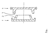
- the synchronous intermediate ring 1 and the counter ring 4 are components of a synchronization device, which is not shown further. Both rings 1, 4 have friction surfaces 2 and 3, which interact during the synchronization process.
- At least one of the friction surfaces 2, 3, preferably both friction surfaces, have an isotropic surface. This is generated by a vibratory grinding process.
- the friction surfaces 2, 3 are first produced in a classical manner by turning, followed by a hardening process. After hardening, the grinding surfaces 2, 4 are vibrated until the roughness R a has a value between 0.1 ⁇ m and 0.3 ⁇ m. Further processing, apart from the sequence of turning - hardening - vibratory grinding, does not take place.
- the proposed vibratory grinding is a working on a chemical-mechanical basis method, with which the friction surfaces 2, 3 can be finished. In this case, grinding bodies (chips) and the workpiece to be machined are brought into a working container in a relative movement to each other. The process is water and a compound buried, which affect the surface treatment.
- the material removal from the workpiece to be machined, the surface appearance and the surface roughness depend on the composition and the size of the abrasive particles (chips). Machine-related factors also influence the material removal, namely the specific grinding pressure exerted on the workpiece.
- abrasive particles (chips) ceramic material steel, stone or plastic can be used.
- compounds ie as a treatment agent solution, aqueous chemical solutions are known, which bind the resulting abrasion and oil and dirt and at the same time participate in the machining process itself.
- the removal of material from the workpiece to be machined takes place during vibratory grinding with the abovementioned grinding bodies or abrasives, which are added to the processing vessel, usually in relation to the volume of the workpieces to be machined, from 3: 1 to 8: 1. This volume ratio of the grinding wheels to the workpieces to be machined prevents the mutual contact of the parts, resulting in a gentle treatment result.
Landscapes
- Engineering & Computer Science (AREA)
- General Engineering & Computer Science (AREA)
- Mechanical Engineering (AREA)
- Mechanical Operated Clutches (AREA)
- Automobile Manufacture Line, Endless Track Vehicle, Trailer (AREA)
- Automatic Assembly (AREA)
- Braking Arrangements (AREA)
- Sliding-Contact Bearings (AREA)
Abstract
Description
- Die Erfindung betrifft ein Bauteil für eine Synchronisationseinrichtung für ein Getriebe, insbesondere für ein Kraftfahrzeuggetriebe, das eine Reibfläche aufweist, die zum Zusammenwirken mit der Reibfläche eines anderen Bauteils der Synchronisationseinrichtung ausgebildet ist, insbesondere einen Synchronzwischenring. Des weiteren betrifft die Erfindung ein Verfahren zur Herstellung eines solchen Bauteils.
- Synchronringe werden in Synchronisationseinrichtungen, insbesondere für Kraftfahrzeuggetriebe, in mannigfaltiger Weise eingesetzt. Sie kommen als Außen-Synchronring, als Innen-Synchronring oder als Synchronzwischenring zum Einsatz. Zumeist ist bei einem Außen-Synchronring an der inneren Mantelfläche und beim Innen-Synchronring an der äußeren Mantelfläche eine Reibfläche ausgebildet; im Falle des Synchronzwischenrings für eine Mehrfach-Synchronisiereinrichtung befindet sich sowohl an der inneren als auch an der äußeren Mantelfläche eine Reibfläche. Um das Reibverhalten zu optimieren und zum Einsatz in einer Synchronisationseinrichtung tauglich zu machen, werden die Reibpaarungen einander zugeordneter Synchronringe zumeist durch Zusammenwirken einer beschichteten und einer unbeschichteten Reibfläche gebildet. Dabei ist die beschichtete Reibfläche mit einem Reibbelag versehen, der beispielsweise aus einem Sinterwerkstoff oder einem Papierwerkstoff gebildet wird und der auf der Oberfläche des Synchronrings aufgebracht wird.
- Synchronringe der gattungsgemäßen Art sind beispielsweise in der DE 198 58 987 A1 offenbart.
- Wenngleich das Reibverhalten der sich im Kontakt befindlichen Synchronisationselemente durch die genannten Maßnahmen bereits relativ gut ist, besteht der Wunsch, es dahingehend zu verbessern, dass sich beim Schaltvorgang zwei in Kontakt befindliche Reibflächen möglichst schnell und lastfrei lösen lassen. Bislang werden Synchronzwischenringe nach dem Drehen und Härten geschliffen und anschließend gehont. Dadurch entsteht eine hinsichtlich des genannten Ziels ungünstige Oberflächenstruktur. Es kommt zu einem relativ hohen Losreißmoment der Reibpartner, was sich beim Schalten nachteilhaft bemerkbar macht.
- Der Erfindung liegt daher die A u f g a b e zugrunde, ein Bauteil für eine Synchronisationseinrichtung der eingangs genannten Art so weiterzubilden, dass die genannten Nachteile vermieden werden, d.h. es soll zu einem verbesserten und möglichst lastfreien Lösen zweier Synchronisationselemente kommen, die sich vor dem Schaltvorgang im Eingriff befinden. Des weiteren soll ein Verfahren zur Herstellung derartiger Bauteile vorgeschlagen werden.
- Die L ö s u n g dieser Aufgabe durch die Erfindung ist hinsichtlich des Bauteils für eine Synchronisationseinrichtung für ein Getriebe dadurch gekennzeichnet, dass die Reibfläche des Bauteils eine isotrope Oberfläche aufweist.
- Unter Isotropie ist in diesem Zusammenhang zu verstehen, dass sich die Oberflächencharakteristika nicht in Abhängigkeit der Richtung ändern, in der sie bestimmt werden. Unabhängig von der Orientierung soll die Oberfläche also eine gleiche Topographie aufweisen. Dies ist im Stand der Technik nicht der Fall, da durch die Schleif- bzw. Hon-Operationen auf der Reiboberfläche eine Orientierung eingearbeitet wird.
- Vorzugsweise ist die isotrope Oberfläche auf dem Bauteil durch einen Gleitschleifvorgang erzeugt.
- Weiterhin ist bevorzugt vorgesehen, dass die Rautiefe der Oberfläche der Reibfläche zwischen Ra = 0,1 µm und Ra = 0,6 µm liegt. Sie liegt bevorzugt in einem Bereich zwischen 0,15 µm und 0,4 µm. Ein anderer bevorzugter Wertebereich der Rautiefe liegt zwischen 0,1 µm und 0,3 µm.
- Das Verfahren zur Herstellung eines Bauteils, insbesondere eines Synchronzwischenrings, für eine Synchronisationseinrichtung für ein Getriebe zeichnet sich dadurch aus, dass folgende Bearbeitungsschritte vorgesehen sind:
- a) Drehen der Reibfläche,
- b) Härten der Reibfläche und
- c) abschließendes Gleitschleifen der Reibfläche.
- Alternativ zu obigem Schritt a) kann auch vorgesehen werden, dass die Reibfläche durch Tiefziehen und/oder Stanzen erzeugt wird.
- Vorzugsweise wird das Gleitschleifen solange durchgeführt, bis die Rautiefe der Oberfläche der Reibfläche zwischen den obengenannten Werten liegt.
- Weiterhin ist bevorzugt vorgesehen, dass die Gleitschleifoperation den letzten Bearbeitungsvorgang der Reibfläche bildet und keine weiteren Vorbearbeitungsvorgänge als das Drehen und das Härten erfolgen.
- Mit dem erfindungsgemäßen Vorschlag wird erreicht, dass sich eine Oberflächenstruktur auf den Reibflächen ausbildet, die sich durch ein besonders geringes Verhaken der Spitzen des "Oberflächengebirges" auszeichnet, was in der Folge zu einem verbesserten Lösen zweier Reibpartner in einer Synchronisationseinrichtung führt.
- In der Zeichnung ist ein Ausführungsbeispiel der Erfindung dargestellt. Die einzige Figur zeigt im Schnitt einen Synchronzwischenring, der mit einem Gegenring zusammenarbeitet.
- Der Synchronzwischenring 1 sowie der Gegenring 4 sind Bestandteile einer Synchronisationseinrichtung, die nicht weiter dargestellt ist. Beide Ringe 1, 4 haben Reibflächen 2 und 3, die beim Synchronisationsvorgang zusammenwirken.
- Zumindest eine der Reibflächen 2, 3, vorzugsweise beide Reibflächen, weisen eine isotrope Oberfläche auf. Diese ist durch einen Gleitschleifvorgang erzeugt.
- Bei der Fertigung werden die Reibflächen 2, 3 zunächst in klassischer Weise durch Drehen hergestellt, woran sich ein Härteprozess anschließt. Nach dem Härten erfolgt ein Gleitschleifen der Reibflächen 2, 4, bis die Rautiefe Ra einen Wert zwischen 0,1 µm und 0,3 µm aufweist. Eine weitere Bearbeitung, abgesehen von der Abfolge Drehen - Härten - Gleitschleifen, erfolgt nicht. Beim vorgeschlagenen Gleitschleifen handelt es sich um ein auf chemischmechanischer Basis arbeitendes Verfahren, mit dem die Reibflächen 2, 3 fertig bearbeitet werden können. Dabei werden Schleifkörper (Chips) und das zu bearbeitende Werkstück in einem Arbeitsbehälter in eine Relativbewegung zueinander gebracht. Dem Prozess wird Wasser und ein Compound beigesetzt, die die Oberflächenbearbeitung beeinflussen.
- Der Materialabtrag vom zu bearbeitenden Werkstück, das Oberflächenbild sowie die Oberflächenrauhigkeit hängen von der Zusammensetzung und der Größe der Schleifkörper (Chips) ab. Auch maschinentechnische Faktoren beeinflussen den Materialabtrag, namentlich der spezifische Schleifdruck, der auf das Werkstück ausgeübt wird.
- Als Schleifkörper (Chips) können keramisches Material, Stahl, Stein oder Kunststoff eingesetzt werden. Als Compounds, d.h. als Behandlungsmittellösung, sind wässrige Chemikalien-Lösungen bekannt, die den entstehenden Abrieb sowie Öl und Schmutz binden und gleichzeitig selber am Bearbeitungsvorgang teilnehmen. Der Abtrag von Werkstoff vom zu bearbeitenden Werkstück erfolgt beim Gleitschleifen mit den erwähnten Schleifkörpern oder Schleifmitteln, die dem Bearbeitungsbehälter zumeist im Verhältnis zum Volumen der zu bearbeitenden Werkstücke von 3 : 1 bis 8 : 1 zugegeben werden. Dieses Volumenverhältnis der Schleifkörper zu den zu bearbeitenden Werkstücken verhindert die gegenseitige Berührung der Teile, was eine schonende Behandlung zur Folge hat.
- Zum Gleitschleifen sind entsprechende Maschinen bekannt, die Trommeln, Glocken bzw. Vibratoren einsetzen, wobei häufig auch auf die Fliehkraft einer rotierenden Trommel eingesetzt wird. Zum Stand der Technik beim Gleitschleifen wird exemplarisch auf die DE 42 36 095 A1 hingewiesen, die eine Fliehkraft-Gleitschleifmaschine offenbart und beschreibt.
- Der Einsatz des Gleitschleifverfahrens als solches ist im Stand der Technik beschrieben, wozu auf die DE 197 04 633 C1, die DE 102 09 264 A1 und die DE 102 16 492 A1 hingewiesen wird.
-
- 1
- Bauteil (Synchronzwischenring)
- 2
- Reibfläche
- 3
- Reibfläche
- 4
- Bauteil (Gegenring)
Claims (10)
- Bauteil (1) für eine Synchronisationseinrichtung für ein Getriebe, insbesondere für ein Kraftfahrzeuggetriebe, das eine Reibfläche (2) aufweist, die zum Zusammenwirken mit der Reibfläche (3) eines anderen Bauteils (4) der Synchronisationseinrichtung ausgebildet ist, insbesondere Synchronzwischenring,
dadurch gekennzeichnet,
dass die Reibfläche (2) eine isotrope Oberfläche aufweist. - Bauteil nach Anspruch 1, dadurch gekennzeichnet, dass die isotrope Oberfläche durch einen Gleitschleifvorgang erzeugt ist.
- Bauteil nach Anspruch 1 oder 2, dadurch gekennzeichnet, dass die Rautiefe der Oberfläche der Reibfläche (2) zwischen Ra = 0,1 µm und Ra = 0,6 µm liegt.
- Bauteil nach Anspruch 3, dadurch gekennzeichnet, dass die Rautiefe der Oberfläche der Reibfläche (2) zwischen Ra = 0,15 µm und Ra = 0,4 µm liegt.
- Verfahren zur Herstellung eines Bauteils (1), insbesondere eines Synchronzwischenring, für eine Synchronisationseinrichtung für ein Getriebe, insbesondere für ein Kraftfahrzeuggetriebe, mit dem eine Reibfläche (2) des Bauteils (1) bearbeitet wird, die zum Zusammenwirken mit der Reibfläche (3) eines anderen Bauteils (4) der Synchronisationseinrichtung ausgebildet ist,
gekennzeichnet durch
die Abfolge der folgenden Bearbeitungsschritte:a) Drehen der Reibfläche (2),b) Härten der Reibfläche (2) undc) abschließendes Gleitschleifen der Reibfläche (2). - Verfahren zur Herstellung eines Bauteils (1), insbesondere eines Synchronzwischenring, für eine Synchronisationseinrichtung für ein Getriebe, insbesondere für ein Kraftfahrzeuggetriebe, mit dem eine Reibfläche (2) des Bauteils (1) bearbeitet wird, die zum Zusammenwirken mit der Reibfläche (3) eines anderen Bauteils (4) der Synchronisationseinrichtung ausgebildet ist,
gekennzeichnet durch
die Abfolge der folgenden Bearbeitungsschritte:a) Herstellen der Reibfläche (2) durch Tiefziehen und/oder Stanzen,b) Härten der Reibfläche (2) undc) abschließendes Gleitschleifen der Reibfläche (2). - Verfahren nach Anspruch 5 oder 6, dadurch gekennzeichnet, dass zwischen Schritt b) und Schritt c) ein Schleifen der Reibfläche (2) erfolgt.
- Verfahren nach einem der Ansprüche 5 bis 7, dadurch gekennzeichnet, dass das Gleitschleifen so lange durchgeführt wird, bis die Rautiefe der Oberfläche der Reibfläche (2) zwischen Ra = 0,1 µm und Ra = 0,6 µm liegt.
- Verfahren nach Anspruch 8, dadurch gekennzeichnet, dass das Gleitschleifen so lange durchgeführt wird, bis die Rautiefe der Oberfläche der Reibfläche (2) zwischen Ra = 0,15 µm und Ra = 0,4 µm liegt.
- Verfahren nach einem der Ansprüche 5 bis 9, dadurch gekennzeichnet, dass die Gleitschleifoperation den letzten Bearbeitungsvorgang der Reibfläche (2) bildet und keine weiteren Vorbearbeitungsvorgänge als das Drehen und das Härten erfolgen.
Applications Claiming Priority (1)
| Application Number | Priority Date | Filing Date | Title |
|---|---|---|---|
| DE102004053000A DE102004053000B3 (de) | 2004-11-03 | 2004-11-03 | Bauteil für eine Synchronisationseinrichtung und Verfahren zu seiner Herstellung |
Publications (2)
| Publication Number | Publication Date |
|---|---|
| EP1655503A1 true EP1655503A1 (de) | 2006-05-10 |
| EP1655503B1 EP1655503B1 (de) | 2007-08-08 |
Family
ID=35560368
Family Applications (1)
| Application Number | Title | Priority Date | Filing Date |
|---|---|---|---|
| EP05021754A Revoked EP1655503B1 (de) | 2004-11-03 | 2005-10-06 | Bauteil für eine Synchronisationseinrichtung und Verfahren zu seiner Herstellung |
Country Status (3)
| Country | Link |
|---|---|
| EP (1) | EP1655503B1 (de) |
| AT (1) | ATE369503T1 (de) |
| DE (2) | DE102004053000B3 (de) |
Cited By (1)
| Publication number | Priority date | Publication date | Assignee | Title |
|---|---|---|---|---|
| CN105805181A (zh) * | 2015-01-21 | 2016-07-27 | 贺尔碧格传动技术控股有限公司 | 用于同步手动变速器的同步器环和同步器环的制造方法 |
Families Citing this family (2)
| Publication number | Priority date | Publication date | Assignee | Title |
|---|---|---|---|---|
| DE102007042800A1 (de) | 2007-09-07 | 2009-03-12 | Schaeffler Kg | Synchronring einer Synchronisiervorrichtung für Getriebe |
| DE102017120803A1 (de) * | 2017-09-08 | 2019-03-14 | Schaeffler Technologies AG & Co. KG | Reibungskupplungseinrichtung mit einem Fliehkraftpendel, vorzugsweise für einen Antriebsstrang eines Kraftfahrzeuges |
Citations (5)
| Publication number | Priority date | Publication date | Assignee | Title |
|---|---|---|---|---|
| FR1521621A (fr) * | 1967-03-10 | 1968-04-19 | Simca Automobiles Sa | Perfectionnement au procédé de fabrication des bagues de synchronisation pour mécanisme de changement de vitesse |
| JPS6138223A (ja) * | 1984-07-30 | 1986-02-24 | Toyota Motor Corp | 同期噛合装置のシンクロナイザ−リング |
| JPS6323049A (ja) * | 1986-07-14 | 1988-01-30 | Toyota Motor Corp | 同期装置のクラツチギア |
| JPH051723A (ja) * | 1991-06-21 | 1993-01-08 | Nippon Piston Ring Co Ltd | シンクロナイザーリング |
| EP1429044A1 (de) * | 2002-12-11 | 2004-06-16 | Otto Fuchs KG | Verfahren zum Herstellen eines im Bereich einer Lagerfläche mit einem reibungsmindernden Belag beschichteten Gegenstandes |
Family Cites Families (9)
| Publication number | Priority date | Publication date | Assignee | Title |
|---|---|---|---|---|
| DE2314348A1 (de) * | 1973-03-22 | 1974-09-26 | Volvo Ab | Flammspritzverfahren zum aufbringen eines verschleissfesten metallueberzugs auf die innenflaeche ringfoermiger gegenstaende |
| DE7342680U (de) * | 1973-11-30 | 1974-03-07 | Sinterstahl Gmbh | Synchronring aus Sinterstahl |
| DE4236095A1 (de) * | 1992-10-26 | 1994-04-28 | Roesler Gleitschlifftech Masch | Fliehkraft-Gleitschleifmaschine |
| DE4240260C1 (de) * | 1992-12-01 | 1994-01-20 | Kopp Kadia Maschinenbau | Entgratwerkzeug |
| DE19704633C1 (de) * | 1997-02-07 | 1998-07-09 | Skf Linearsysteme Gmbh | Kugellager für Längsbewegungen |
| DE19858987A1 (de) * | 1998-12-21 | 2000-06-29 | Schaeffler Waelzlager Ohg | Spanlos gefertigter Synchronring mit strukturierten Reibflächen |
| DE10035489B4 (de) * | 2000-07-21 | 2005-03-17 | Ina-Schaeffler Kg | Reibpaarung |
| DE10209264B4 (de) * | 2002-03-01 | 2005-06-02 | Ab Skf | Verfahren zum Herstellen eines Bauteils aus Metall |
| DE10216492B4 (de) * | 2002-04-13 | 2005-07-21 | Ab Skf | Verfahren zum Herstellen eines Wälzlager-Bauteils aus Metall |
-
2004
- 2004-11-03 DE DE102004053000A patent/DE102004053000B3/de not_active Revoked
-
2005
- 2005-10-06 DE DE502005001175T patent/DE502005001175D1/de not_active Revoked
- 2005-10-06 AT AT05021754T patent/ATE369503T1/de not_active IP Right Cessation
- 2005-10-06 EP EP05021754A patent/EP1655503B1/de not_active Revoked
Patent Citations (5)
| Publication number | Priority date | Publication date | Assignee | Title |
|---|---|---|---|---|
| FR1521621A (fr) * | 1967-03-10 | 1968-04-19 | Simca Automobiles Sa | Perfectionnement au procédé de fabrication des bagues de synchronisation pour mécanisme de changement de vitesse |
| JPS6138223A (ja) * | 1984-07-30 | 1986-02-24 | Toyota Motor Corp | 同期噛合装置のシンクロナイザ−リング |
| JPS6323049A (ja) * | 1986-07-14 | 1988-01-30 | Toyota Motor Corp | 同期装置のクラツチギア |
| JPH051723A (ja) * | 1991-06-21 | 1993-01-08 | Nippon Piston Ring Co Ltd | シンクロナイザーリング |
| EP1429044A1 (de) * | 2002-12-11 | 2004-06-16 | Otto Fuchs KG | Verfahren zum Herstellen eines im Bereich einer Lagerfläche mit einem reibungsmindernden Belag beschichteten Gegenstandes |
Non-Patent Citations (3)
| Title |
|---|
| PATENT ABSTRACTS OF JAPAN vol. 010, no. 193 (M - 496) 8 July 1986 (1986-07-08) * |
| PATENT ABSTRACTS OF JAPAN vol. 012, no. 227 (M - 713) 28 June 1988 (1988-06-28) * |
| PATENT ABSTRACTS OF JAPAN vol. 017, no. 263 (M - 1415) 24 May 1993 (1993-05-24) * |
Cited By (2)
| Publication number | Priority date | Publication date | Assignee | Title |
|---|---|---|---|---|
| CN105805181A (zh) * | 2015-01-21 | 2016-07-27 | 贺尔碧格传动技术控股有限公司 | 用于同步手动变速器的同步器环和同步器环的制造方法 |
| CN105805181B (zh) * | 2015-01-21 | 2019-04-12 | 贺尔碧格传动技术控股有限公司 | 用于同步手动变速器的同步器环和同步器环的制造方法 |
Also Published As
| Publication number | Publication date |
|---|---|
| DE102004053000B3 (de) | 2006-07-06 |
| EP1655503B1 (de) | 2007-08-08 |
| ATE369503T1 (de) | 2007-08-15 |
| DE502005001175D1 (de) | 2007-09-20 |
Similar Documents
| Publication | Publication Date | Title |
|---|---|---|
| DE19802842C2 (de) | Verfahren zum maschinellen Bearbeiten einer Bohrungsoberfläche eines Zylinderblocks und Vorrichtung dafür | |
| EP3237164B1 (de) | Bohrring für eine kernbohrkrone | |
| EP2459895B1 (de) | Synchronringpaket | |
| WO1999024197A1 (de) | Kurbelwelle spanen + härten + spanen + finishen | |
| DE19714677A1 (de) | Kurbelwelle Spanen + Finishen | |
| EP3756809A1 (de) | Verfahren zur fertigung eines verzahnungsbauteils und verzahnungsschleifmaschine | |
| DE69811733T2 (de) | Punktkontaktverdichtung von gesintertem metallpulver | |
| EP3148745B1 (de) | Honverfahren zur feinbearbeitung von bohrungen | |
| EP1669621A1 (de) | Spanneinrichtung | |
| EP2181273A1 (de) | Verfahren zum herstellen eines zu einer reibpaarung gehörenden körpers sowie zu einer reibpaarung gehörender körper | |
| EP1655503B1 (de) | Bauteil für eine Synchronisationseinrichtung und Verfahren zu seiner Herstellung | |
| EP2167265B1 (de) | Bruchtrennmodul für eine werkzeugmaschine, werkzeugmaschine mit einem bruchtrennmodul und verfahren zum bruchtrennen | |
| DE3524412C2 (de) | ||
| DE19607774A1 (de) | Zylinder und Verfahren zum Honen seiner Innenflächen | |
| WO2008074560A2 (de) | Verfahren zur herstellung eines synchronringes einer synchronisiereinrichtung | |
| EP3625475B1 (de) | Reibring für eine bremsscheibe, bremsscheibe sowie zugehöriges fertigungsverfahren | |
| EP1236539A2 (de) | Verfahren zum Honbearbeiten | |
| DE602004006149T3 (de) | Schleifgerät, dessen Anwendung zum Schleifen von zylindrischen Gegenständen , Vorrichtung und Verfahren zum Schleifen von zylindrischen Gegenständen | |
| DE102016005047A1 (de) | Rollierwerkzeug | |
| DE102006006146B3 (de) | Verfahren zur Herstellung eines Massivkäfigs eines Wälzlagers und Wälzlagerkäfig | |
| DE102017217933A1 (de) | Verfahren und Vorrichtung zur Herstellung eines Zahnradbauteils eines Getriebes, insbesondere eines Windkraft-Planetengetriebes | |
| DE4334497A1 (de) | Synchronring und Verfahren zu seiner Herstellung | |
| DE102020121239A1 (de) | Verfahren zur Herstellung einer Schiebemuffe für eine Synchronisierungseinheit, Schiebemuffe sowie Synchronisierungseinheit | |
| WO2016142473A1 (de) | Verfahren für eine definierte oberflächenbearbeitung einer auf einer oberfläche eines bauteils aufgebrachten ersten kohlenstoffbeschichtung | |
| DE102015223180A1 (de) | Verfahren zum Fertigen eines Massivbauteils sowie ein Massivbauteil |
Legal Events
| Date | Code | Title | Description |
|---|---|---|---|
| PUAI | Public reference made under article 153(3) epc to a published international application that has entered the european phase |
Free format text: ORIGINAL CODE: 0009012 |
|
| 17P | Request for examination filed |
Effective date: 20060216 |
|
| AK | Designated contracting states |
Kind code of ref document: A1 Designated state(s): AT BE BG CH CY CZ DE DK EE ES FI FR GB GR HU IE IS IT LI LT LU LV MC NL PL PT RO SE SI SK TR |
|
| AX | Request for extension of the european patent |
Extension state: AL BA HR MK YU |
|
| AKX | Designation fees paid |
Designated state(s): AT BE BG CH CY CZ DE DK EE ES FI FR GB GR HU IE IS IT LI LT LU LV MC NL PL PT RO SE SI SK TR |
|
| GRAP | Despatch of communication of intention to grant a patent |
Free format text: ORIGINAL CODE: EPIDOSNIGR1 |
|
| GRAS | Grant fee paid |
Free format text: ORIGINAL CODE: EPIDOSNIGR3 |
|
| GRAA | (expected) grant |
Free format text: ORIGINAL CODE: 0009210 |
|
| AK | Designated contracting states |
Kind code of ref document: B1 Designated state(s): AT BE BG CH CY CZ DE DK EE ES FI FR GB GR HU IE IS IT LI LT LU LV MC NL PL PT RO SE SI SK TR |
|
| REG | Reference to a national code |
Ref country code: GB Ref legal event code: FG4D Free format text: NOT ENGLISH |
|
| REG | Reference to a national code |
Ref country code: CH Ref legal event code: EP |
|
| REG | Reference to a national code |
Ref country code: IE Ref legal event code: FG4D Free format text: LANGUAGE OF EP DOCUMENT: GERMAN |
|
| REF | Corresponds to: |
Ref document number: 502005001175 Country of ref document: DE Date of ref document: 20070920 Kind code of ref document: P |
|
| GBT | Gb: translation of ep patent filed (gb section 77(6)(a)/1977) |
Effective date: 20070927 |
|
| ET | Fr: translation filed | ||
| PG25 | Lapsed in a contracting state [announced via postgrant information from national office to epo] |
Ref country code: FI Free format text: LAPSE BECAUSE OF FAILURE TO SUBMIT A TRANSLATION OF THE DESCRIPTION OR TO PAY THE FEE WITHIN THE PRESCRIBED TIME-LIMIT Effective date: 20070808 Ref country code: IS Free format text: LAPSE BECAUSE OF FAILURE TO SUBMIT A TRANSLATION OF THE DESCRIPTION OR TO PAY THE FEE WITHIN THE PRESCRIBED TIME-LIMIT Effective date: 20071208 Ref country code: NL Free format text: LAPSE BECAUSE OF FAILURE TO SUBMIT A TRANSLATION OF THE DESCRIPTION OR TO PAY THE FEE WITHIN THE PRESCRIBED TIME-LIMIT Effective date: 20070808 Ref country code: LT Free format text: LAPSE BECAUSE OF FAILURE TO SUBMIT A TRANSLATION OF THE DESCRIPTION OR TO PAY THE FEE WITHIN THE PRESCRIBED TIME-LIMIT Effective date: 20070808 Ref country code: BG Free format text: LAPSE BECAUSE OF FAILURE TO SUBMIT A TRANSLATION OF THE DESCRIPTION OR TO PAY THE FEE WITHIN THE PRESCRIBED TIME-LIMIT Effective date: 20071108 Ref country code: ES Free format text: LAPSE BECAUSE OF FAILURE TO SUBMIT A TRANSLATION OF THE DESCRIPTION OR TO PAY THE FEE WITHIN THE PRESCRIBED TIME-LIMIT Effective date: 20071119 |
|
| NLV1 | Nl: lapsed or annulled due to failure to fulfill the requirements of art. 29p and 29m of the patents act | ||
| PG25 | Lapsed in a contracting state [announced via postgrant information from national office to epo] |
Ref country code: PL Free format text: LAPSE BECAUSE OF FAILURE TO SUBMIT A TRANSLATION OF THE DESCRIPTION OR TO PAY THE FEE WITHIN THE PRESCRIBED TIME-LIMIT Effective date: 20070808 |
|
| PG25 | Lapsed in a contracting state [announced via postgrant information from national office to epo] |
Ref country code: LV Free format text: LAPSE BECAUSE OF FAILURE TO SUBMIT A TRANSLATION OF THE DESCRIPTION OR TO PAY THE FEE WITHIN THE PRESCRIBED TIME-LIMIT Effective date: 20070808 |
|
| REG | Reference to a national code |
Ref country code: IE Ref legal event code: FD4D |
|
| BERE | Be: lapsed |
Owner name: A.B. SKF Effective date: 20071031 |
|
| PG25 | Lapsed in a contracting state [announced via postgrant information from national office to epo] |
Ref country code: GR Free format text: LAPSE BECAUSE OF FAILURE TO SUBMIT A TRANSLATION OF THE DESCRIPTION OR TO PAY THE FEE WITHIN THE PRESCRIBED TIME-LIMIT Effective date: 20071109 Ref country code: DK Free format text: LAPSE BECAUSE OF FAILURE TO SUBMIT A TRANSLATION OF THE DESCRIPTION OR TO PAY THE FEE WITHIN THE PRESCRIBED TIME-LIMIT Effective date: 20070808 |
|
| PLBI | Opposition filed |
Free format text: ORIGINAL CODE: 0009260 |
|
| PG25 | Lapsed in a contracting state [announced via postgrant information from national office to epo] |
Ref country code: CZ Free format text: LAPSE BECAUSE OF FAILURE TO SUBMIT A TRANSLATION OF THE DESCRIPTION OR TO PAY THE FEE WITHIN THE PRESCRIBED TIME-LIMIT Effective date: 20070808 Ref country code: IE Free format text: LAPSE BECAUSE OF FAILURE TO SUBMIT A TRANSLATION OF THE DESCRIPTION OR TO PAY THE FEE WITHIN THE PRESCRIBED TIME-LIMIT Effective date: 20070808 Ref country code: SK Free format text: LAPSE BECAUSE OF FAILURE TO SUBMIT A TRANSLATION OF THE DESCRIPTION OR TO PAY THE FEE WITHIN THE PRESCRIBED TIME-LIMIT Effective date: 20070808 Ref country code: MC Free format text: LAPSE BECAUSE OF NON-PAYMENT OF DUE FEES Effective date: 20071031 Ref country code: PT Free format text: LAPSE BECAUSE OF FAILURE TO SUBMIT A TRANSLATION OF THE DESCRIPTION OR TO PAY THE FEE WITHIN THE PRESCRIBED TIME-LIMIT Effective date: 20080108 |
|
| 26 | Opposition filed |
Opponent name: HOERBIGER ANTRIEBSTECHNIK GMBH Effective date: 20080508 Opponent name: DIEHL METALL STIFTUNG & CO.KG Effective date: 20080508 |
|
| PLAX | Notice of opposition and request to file observation + time limit sent |
Free format text: ORIGINAL CODE: EPIDOSNOBS2 |
|
| PG25 | Lapsed in a contracting state [announced via postgrant information from national office to epo] |
Ref country code: SE Free format text: LAPSE BECAUSE OF FAILURE TO SUBMIT A TRANSLATION OF THE DESCRIPTION OR TO PAY THE FEE WITHIN THE PRESCRIBED TIME-LIMIT Effective date: 20071108 Ref country code: RO Free format text: LAPSE BECAUSE OF FAILURE TO SUBMIT A TRANSLATION OF THE DESCRIPTION OR TO PAY THE FEE WITHIN THE PRESCRIBED TIME-LIMIT Effective date: 20070808 |
|
| PLAB | Opposition data, opponent's data or that of the opponent's representative modified |
Free format text: ORIGINAL CODE: 0009299OPPO |
|
| PG25 | Lapsed in a contracting state [announced via postgrant information from national office to epo] |
Ref country code: BE Free format text: LAPSE BECAUSE OF NON-PAYMENT OF DUE FEES Effective date: 20071031 |
|
| PLBB | Reply of patent proprietor to notice(s) of opposition received |
Free format text: ORIGINAL CODE: EPIDOSNOBS3 |
|
| PG25 | Lapsed in a contracting state [announced via postgrant information from national office to epo] |
Ref country code: EE Free format text: LAPSE BECAUSE OF FAILURE TO SUBMIT A TRANSLATION OF THE DESCRIPTION OR TO PAY THE FEE WITHIN THE PRESCRIBED TIME-LIMIT Effective date: 20070808 |
|
| PG25 | Lapsed in a contracting state [announced via postgrant information from national office to epo] |
Ref country code: AT Free format text: LAPSE BECAUSE OF NON-PAYMENT OF DUE FEES Effective date: 20071006 |
|
| PG25 | Lapsed in a contracting state [announced via postgrant information from national office to epo] |
Ref country code: SI Free format text: LAPSE BECAUSE OF FAILURE TO SUBMIT A TRANSLATION OF THE DESCRIPTION OR TO PAY THE FEE WITHIN THE PRESCRIBED TIME-LIMIT Effective date: 20070808 |
|
| PG25 | Lapsed in a contracting state [announced via postgrant information from national office to epo] |
Ref country code: CY Free format text: LAPSE BECAUSE OF FAILURE TO SUBMIT A TRANSLATION OF THE DESCRIPTION OR TO PAY THE FEE WITHIN THE PRESCRIBED TIME-LIMIT Effective date: 20070808 |
|
| PG25 | Lapsed in a contracting state [announced via postgrant information from national office to epo] |
Ref country code: LU Free format text: LAPSE BECAUSE OF NON-PAYMENT OF DUE FEES Effective date: 20071006 |
|
| PLAB | Opposition data, opponent's data or that of the opponent's representative modified |
Free format text: ORIGINAL CODE: 0009299OPPO |
|
| PG25 | Lapsed in a contracting state [announced via postgrant information from national office to epo] |
Ref country code: TR Free format text: LAPSE BECAUSE OF FAILURE TO SUBMIT A TRANSLATION OF THE DESCRIPTION OR TO PAY THE FEE WITHIN THE PRESCRIBED TIME-LIMIT Effective date: 20070808 Ref country code: HU Free format text: LAPSE BECAUSE OF FAILURE TO SUBMIT A TRANSLATION OF THE DESCRIPTION OR TO PAY THE FEE WITHIN THE PRESCRIBED TIME-LIMIT Effective date: 20080209 |
|
| R26 | Opposition filed (corrected) |
Opponent name: HOERBIGER ANTRIEBSTECHNIK GMBH Effective date: 20080508 Opponent name: DIEHL METALL STIFTUNG & CO.KG Effective date: 20080508 |
|
| REG | Reference to a national code |
Ref country code: CH Ref legal event code: PL |
|
| PG25 | Lapsed in a contracting state [announced via postgrant information from national office to epo] |
Ref country code: LI Free format text: LAPSE BECAUSE OF NON-PAYMENT OF DUE FEES Effective date: 20091031 Ref country code: CH Free format text: LAPSE BECAUSE OF NON-PAYMENT OF DUE FEES Effective date: 20091031 |
|
| RDAF | Communication despatched that patent is revoked |
Free format text: ORIGINAL CODE: EPIDOSNREV1 |
|
| PGFP | Annual fee paid to national office [announced via postgrant information from national office to epo] |
Ref country code: FR Payment date: 20101105 Year of fee payment: 6 |
|
| PG25 | Lapsed in a contracting state [announced via postgrant information from national office to epo] |
Ref country code: IT Free format text: LAPSE BECAUSE OF NON-PAYMENT OF DUE FEES Effective date: 20071031 |
|
| PGFP | Annual fee paid to national office [announced via postgrant information from national office to epo] |
Ref country code: DE Payment date: 20101027 Year of fee payment: 6 |
|
| RDAG | Patent revoked |
Free format text: ORIGINAL CODE: 0009271 |
|
| STAA | Information on the status of an ep patent application or granted ep patent |
Free format text: STATUS: PATENT REVOKED |
|
| PGFP | Annual fee paid to national office [announced via postgrant information from national office to epo] |
Ref country code: GB Payment date: 20101025 Year of fee payment: 6 |
|
| 27W | Patent revoked |
Effective date: 20101012 |
|
| GBPR | Gb: patent revoked under art. 102 of the ep convention designating the uk as contracting state |
Effective date: 20101012 |