EP1647441A2 - Sitz für ein Kraftfahrzeug - Google Patents
Sitz für ein Kraftfahrzeug Download PDFInfo
- Publication number
- EP1647441A2 EP1647441A2 EP05020043A EP05020043A EP1647441A2 EP 1647441 A2 EP1647441 A2 EP 1647441A2 EP 05020043 A EP05020043 A EP 05020043A EP 05020043 A EP05020043 A EP 05020043A EP 1647441 A2 EP1647441 A2 EP 1647441A2
- Authority
- EP
- European Patent Office
- Prior art keywords
- seat
- profile
- latching
- lug
- support
- Prior art date
- Legal status (The legal status is an assumption and is not a legal conclusion. Google has not performed a legal analysis and makes no representation as to the accuracy of the status listed.)
- Granted
Links
Images
Classifications
-
- B—PERFORMING OPERATIONS; TRANSPORTING
- B60—VEHICLES IN GENERAL
- B60N—SEATS SPECIALLY ADAPTED FOR VEHICLES; VEHICLE PASSENGER ACCOMMODATION NOT OTHERWISE PROVIDED FOR
- B60N2/00—Seats specially adapted for vehicles; Arrangement or mounting of seats in vehicles
- B60N2/58—Seat coverings
- B60N2/5816—Seat coverings attachments thereof
- B60N2/5825—Seat coverings attachments thereof by hooks, staples, clips, snap fasteners or the like
Definitions
- the invention relates to a seat for a motor vehicle according to the preamble of claim 1.
- the object of the invention is to provide an improved attachment for a seat cover to a vehicle seat, which ensures in a simple manner a tense setting on the seat support and also allows easy removal of the seat cover.
- the seat cover is placed around the seat edge, clamped on the seat support can be fastened, wherein the hooking from the underside of the seat forth by means of an insertable into an open, enclosed profile bar, which hooks on locking elements ,
- an outwardly open profile is arranged, which has at least one locking lug, which is overlapped by at least one corresponding with this locking element of the seat cover.
- the hollow profile is embedded in the seat carrier and arranged foamed and in cross section it consists of a U-profile and at least one profile inner wall, the inwardly projecting locking lug is arranged, which is for example wedge-shaped.
- a plate-shaped strip is connected, which has the hook-shaped locking element, which engages over the latching lug.
- opposite the detent has a free edge of the profile inwardly a shutdown and forms a support edge for the plate-shaped bar approximately in the central region.
- the plate-shaped strip with the latching element is arranged diagonally in the U-profile in a plane X-X and is held supported on the latching lug on the one hand on the off-set and on the other hand on the opposite inner wall.
- the hollow profile on the inside on its opposite wall each having a detent and on both sides of the bar latching elements are arranged which form a latching with the corresponding latching lugs.
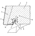
- FIG. 1 An embodiment of the invention is illustrated in the drawing, which shows a seat or a seat base with a fastening device for a seat cover in section.
- a front part of a seat member 1 of a vehicle seat 2 is shown for a motor vehicle, wherein a front portion 3 of the seat base 1 consists of a foam element 4, which extends over a seat, which is not shown in detail, extends.
- the foam element 4 envelops a seat support 5, which is supported on the vehicle body 6, which is only hinted at.
- a fastening device 8 for a seat cover 9 is arranged on its underside 7.
- This fastening device 8 comprises a hooking connection between a latching lug 10 on the seat carrier 5 and a hook-shaped latching element 11 on the seat cover 9.
- the seat support 5 has an outwardly open U-profile 12, which is preferably foamed in this seat support 5 or otherwise held. At least one inner wall of the profile 12, the locking lug 10 is arranged. This is provided corresponding to the locking element 11, which is preferably integrally formed on a plate-shaped strip 13 which is firmly connected to the seat cover 9.
- the bar 13 with end-side locking element 11 is supported on a projecting into the interior of the profile 12 Abstell 14, so that the bar 13 assumes a diagonal position in the profile 12.
- This shutdown 14 is designed as a repository, so that no significant support on the seat support 5 itself.
Landscapes
- Engineering & Computer Science (AREA)
- Aviation & Aerospace Engineering (AREA)
- Transportation (AREA)
- Mechanical Engineering (AREA)
- Seats For Vehicles (AREA)
Abstract
Description
- Die Erfindung bezieht sich auf einen Sitz für ein Kraftfahrzeug nach dem Oberbegriff des Anspruchs 1.
- Aus der DE 299 10 294 U1 ist eine Befestigung für einen Sitzbezug an einem Sitzträger mittels eines Klemmelements bekannt, das aus einem sogenannten Tannenbaumprofil besteht, welches sich in einer Rinne des Sitzträgers klemmend verhakt und den Sitzbezug positioniert am Sitzträger festsetzt.
- Aufgabe der Erfindung ist es, eine verbesserte Befestigung für einen Sitzbezug an einem Fahrzeugsitz zu schaffen, die in einfacher Weise ein gespanntes Festsetzen am Sitzträger gewährleistet und darüber hinaus auch ein einfaches Entfernen des Sitzbezugs ermöglicht.
- Diese Aufgabe wird erfindungsgemäß durch die Merkmale des Patentanspruchs 1 gelöst. Weitere vorteilhafte Merkmale beinhalten die Unteransprüche.
- Die mit der Erfindung hauptsächlich erzielten Vorteile bestehen darin, dass der Sitzbezug um die Sitzkante herumgelegt, gespannt am Sitzträger befestigbar ist, wobei der Einhakvorgang von der Unterseite des Sitzes her mittels einer in ein offenes, eingeschlossenes Profil einsteckbare Leiste erfolgt, die sich über Rastelemente verhakt. Insbesondere ist nach der Erfindung im Sitzträger ein nach außen hin geöffnetes Profil angeordnet, welches mindestens eine Rastnase aufweist, die von mindestens einem mit diesem korrespondierenden Rastelement des Sitzbezugs übergriffen wird.
- Das Hohlprofil ist in den Sitzträger eingelassen und eingeschäumt angeordnet und im Querschnitt besteht es aus einem U-Profil und an mindestens einer Profilinnenwand ist die nach innen vorstehende Rastnase angeordnet, welche beispielsweise keilförmig ausgebildet ist. Durch diese Verrastung zwischen der Rastnase im Profil und dem Rastelement am Sitzbezug wird eine dauerhaft haltbare Spannbefestigung am Sitzträger erzielt, die zudem noch in einfacher Montageweise einsetzbar ist.
- Damit eine stabile Verbindung zwischen dem Rastelement und dem Sitzbezug erzielbar ist, ist nach der Erfindung des Weiteren vorgesehen, dass mit dem freien Kantenende des Sitzbezugs eine plattenförmige Leiste verbunden ist, die endseitig das hakenförmige Rastelement aufweist, welches die Rastnase übergreift. Durch diese Leiste ist ein Einführen in das U-Profil gezielt möglich.
- Zum Hintergreifen der Rastnase am Profil über das Rastelement und zur Abstützung am Hohlprofil ist nach der Erfindung ferner vorgesehen, dass gegenüberliegend der Rastnase eine freie Kante des Profils nach innen hin eine Abstellung aufweist und eine Abstützkante für die plattenförmige Leiste etwa im mittleren Bereich bildet. Hierdurch wird insbesondere auch erreicht, dass die plattenförmige Leiste mit dem Rastelement diagonal im U-Profil in einer Ebene X-X angeordnet ist und sich einerseits an der Abstellung und andererseits an der gegenüberliegenden Innenwandung an der Rastnase abgestützt gehalten ist.
- Nach einer weiteren Ausführung der Erfindung kann das Hohlprofil innenseitig an seiner gegenüberliegenden Wandung jeweils eine Rastnase aufweisen und zu beiden Seiten der Leiste sind Rastelemente angeordnet, die eine Verrastung mit der zu diesen korrespondierenden Rastnasen bilden.
- Ein Ausführungsbeispiel der Erfindung ist in der Zeichnung dargestellt, welche einen Sitz bzw. ein Sitzunterteil mit einer Befestigungsvorrichtung für einen Sitzbezug im Schnitt zeigt.
- In der Zeichnung ist ein vorderer Teil eines Sitzelements 1 eines Fahrzeugsitzes 2 für ein Kraftfahrzeug dargestellt, wobei ein vorderer Bereich 3 des Sitzunterteils 1 aus einem Schaumelement 4 besteht, das sich über eine Sitzfläche, die nicht näher dargestellt ist, erstreckt. Das Schaumelement 4 umhüllt einen Sitzträger 5, der sich am Fahrzeugaufbau 6 abstützt, welcher nur angedeutet ist.
- Im Sitzträger 5 ist an seiner Unterseite 7 eine Befestigungseinrichtung 8 für einen Sitzbezug 9 angeordnet. Diese Befestigungseinrichtung 8 umfasst eine Einhakverbindung zwischen einer Rastnase 10 am Sitzträger 5 und einem hakenförmigen Rastelement 11 am Sitzbezug 9.
- Der Sitzträger 5 weist ein nach außen hin geöffnetes U-Profil 12 auf, das vorzugsweise in diesem Sitzträger 5 eingeschäumt oder sonst wie gehalten ist. An mindestens einer Innenwandung des Profils 12 ist die Rastnase 10 angeordnet. Diese ist korrespondierend mit dem Rastelement 11 vorgesehen, das vorzugsweise an einer plattenförmigen Leiste 13 angeformt ist, die fest mit dem Sitzbezug 9 verbunden wird.
- Die Leiste 13 mit endseitigem Rastelement 11 stützt sich an einer ins Innere des Profils 12 ragenden Abstellung 14 ab, so dass die Leiste 13 eine diagonale Lage im Profil 12 einnimmt. Diese Abstellung 14 ist als Wiederlager ausgelegt, so dass keine wesentliche Abstützung am Sitzträger 5 selbst erfolgt.
- Zum Festsetzen des Sitzbezugs 9 am Sitzunterteil 2 wird die sich über die gesamte Breite des Sitzunterteils 1 verlaufende Leiste 13 in das ebenfalls über die gesamte Breite des Sitzträgers 5 verlaufende Profil 12 eingeführt, derart, dass das Rastelement 11 die Rastnase 10 hintergreifen kann, wobei sich die Leiste 13 an der Abstellung 14 abstützt. Ein Lösen dieser Rastverbindung ist ebenfalls durch ein einfaches Hineinschieben der Leiste 13 in das Profil 12 möglich, indem sich dann die Rastverbindung wieder lösen kann.
Claims (6)
- Sitz für ein Kraftfahrzeug mit einem von einem Sitzbezug umhüllten Sitzunterteil, das einen Sitzträger und ein dieses teilweise umgebendes Schaumelement umfasst und der Sitzbezug über Befestigungsmittel mit dem Sitzträger verbindbar ist, dadurch gekennzeichnet, dass im Sitzträger (5) ein nach außen hin geöffnetes Profil (12) angeordnet ist, welches mindestens eine Rastnase (10) aufweist, die von mindestens einem mit dieser Rastnase (10) korrespondierenden Rastelement (11) des Sitzbezugs (9) übergriffen wird.
- Sitz nach Anspruch 1, dadurch gekennzeichnet, dass das Profil (12) in den Sitzträger (5) eingelassen und eingeschäumt angeordnet ist und im Querschnitt aus einem U-Profil besteht und an mindestens einer Profilinnenwandung die nach innen vorstehende Rastnase (10) angeordnet ist.
- Sitz nach den Ansprüchen 1 oder 2, dadurch gekennzeichnet, dass mit dem freien Kantenende des Sitzbezugs (9) eine plattenförmige Leiste (13) fest verbunden ist, die endseitig ein hakenförmiges Rastelement (11) aufweist, das die Rastnase (10) übergreift.
- Sitz nach den Ansprüchen 1, 2 oder 3, dadurch gekennzeichnet, dass gegenüberliegend der Rastnase (10) an einer freien Kante des Profils (12) eine nach innen gerichtete Abstellung (14) vorgesehen ist und diese eine Abstützkante für die plattenförmige Leiste (13) etwa im mittleren Bereich bildet.
- Sitz nach einem der vorhergehenden Ansprüche, dadurch gekennzeichnet, dass die plattenförmige Leiste (13) mit dem Rastelement (11) diagonal im Profil (12) in einer Ebene (X-X) angeordnet ist und sich einerseits an der Abstellung (14) und andererseits an der gegenüberliegenden Innenwandung an der Rastnase (10) abstützt.
- Sitz nach einem der vorhergehenden Ansprüche, dadurch gekennzeichnet, dass das Profil (12) innenseitig an seinen gegenüberliegenden Wandungen jeweils eine Rastnase (10) aufweist und zu beiden Seiten der Leiste (13) das Rastelement (11) angeordnet ist, welches eine Verrastung mit der zu diesen Rastelementen (11) korrespondierend angeordneten Rastnasen (10) bildet.
Applications Claiming Priority (1)
| Application Number | Priority Date | Filing Date | Title |
|---|---|---|---|
| DE200410049929 DE102004049929B4 (de) | 2004-10-14 | 2004-10-14 | Sitz für ein Kraftfahrzeug |
Publications (3)
| Publication Number | Publication Date |
|---|---|
| EP1647441A2 true EP1647441A2 (de) | 2006-04-19 |
| EP1647441A3 EP1647441A3 (de) | 2009-11-25 |
| EP1647441B1 EP1647441B1 (de) | 2011-01-26 |
Family
ID=35429202
Family Applications (1)
| Application Number | Title | Priority Date | Filing Date |
|---|---|---|---|
| EP20050020043 Expired - Lifetime EP1647441B1 (de) | 2004-10-14 | 2005-09-15 | Sitz für ein Kraftfahrzeug |
Country Status (2)
| Country | Link |
|---|---|
| EP (1) | EP1647441B1 (de) |
| DE (2) | DE102004049929B4 (de) |
Cited By (1)
| Publication number | Priority date | Publication date | Assignee | Title |
|---|---|---|---|---|
| FR2937921A1 (fr) * | 2008-10-31 | 2010-05-07 | Cera | Composant de garnissage de vehicule automobile |
Families Citing this family (1)
| Publication number | Priority date | Publication date | Assignee | Title |
|---|---|---|---|---|
| DE102011018567A1 (de) * | 2011-04-26 | 2012-10-31 | GM Global Technology Operations LLC (n. d. Gesetzen des Staates Delaware) | Befestigungssystem, Bezugsvorrichtung, Sitzeinrichtung und Fahrzeug |
Citations (5)
| Publication number | Priority date | Publication date | Assignee | Title |
|---|---|---|---|---|
| GB1428507A (en) | 1972-08-25 | 1976-03-17 | Nystrom Kg | Upholstered part of a chair or the like |
| DE4313813A1 (de) | 1993-04-27 | 1994-11-03 | Bayerische Motoren Werke Ag | Befestigung eines Teils eines Sitzaufbaus wie Polsterbezug oder dergleichen an einem Sitz- oder Lehnenrahmen, insbesondere eines Kraftfahrzeugsitzes |
| WO1998008703A1 (en) | 1996-08-30 | 1998-03-05 | Woodbridge Foam Corporation | Seat, and process, mold and system for production thereof |
| DE29910294U1 (de) | 1999-06-12 | 1999-08-12 | Bertrand Faure Sitztechnik GmbH & Co. KG, 31655 Stadthagen | Kraftfahrzeug-Sitzkissenträger |
| JP2000038060A (ja) | 1998-07-23 | 2000-02-08 | Tachi S Co Ltd | 乗り物シート |
Family Cites Families (4)
| Publication number | Priority date | Publication date | Assignee | Title |
|---|---|---|---|---|
| DE3618057A1 (de) * | 1985-06-08 | 1986-12-11 | Volkswagen AG, 3180 Wolfsburg | Befestigung eines polsterbezuges an einem sitz- oder lehnenrahmen, insbesondere bei einem kraftfahrzeug |
| DE3841531A1 (de) * | 1988-12-09 | 1990-06-13 | Bayer Ag | Befestigung zwischen einem polsterbezug und einem das polster aufnehmenden traeger |
| US5820213A (en) * | 1997-07-23 | 1998-10-13 | Lear Corporation | Trim cover attachment feature |
| DE10120118B4 (de) * | 2001-04-25 | 2005-04-07 | Franz Kiel Gmbh & Co. Kg | Fahrgastsitz |
-
2004
- 2004-10-14 DE DE200410049929 patent/DE102004049929B4/de not_active Expired - Fee Related
-
2005
- 2005-09-15 DE DE200550010905 patent/DE502005010905D1/de not_active Expired - Lifetime
- 2005-09-15 EP EP20050020043 patent/EP1647441B1/de not_active Expired - Lifetime
Patent Citations (5)
| Publication number | Priority date | Publication date | Assignee | Title |
|---|---|---|---|---|
| GB1428507A (en) | 1972-08-25 | 1976-03-17 | Nystrom Kg | Upholstered part of a chair or the like |
| DE4313813A1 (de) | 1993-04-27 | 1994-11-03 | Bayerische Motoren Werke Ag | Befestigung eines Teils eines Sitzaufbaus wie Polsterbezug oder dergleichen an einem Sitz- oder Lehnenrahmen, insbesondere eines Kraftfahrzeugsitzes |
| WO1998008703A1 (en) | 1996-08-30 | 1998-03-05 | Woodbridge Foam Corporation | Seat, and process, mold and system for production thereof |
| JP2000038060A (ja) | 1998-07-23 | 2000-02-08 | Tachi S Co Ltd | 乗り物シート |
| DE29910294U1 (de) | 1999-06-12 | 1999-08-12 | Bertrand Faure Sitztechnik GmbH & Co. KG, 31655 Stadthagen | Kraftfahrzeug-Sitzkissenträger |
Cited By (2)
| Publication number | Priority date | Publication date | Assignee | Title |
|---|---|---|---|---|
| FR2937921A1 (fr) * | 2008-10-31 | 2010-05-07 | Cera | Composant de garnissage de vehicule automobile |
| EP2186676A1 (de) * | 2008-10-31 | 2010-05-19 | Centre d'etude et de recherche pour l'automobile (CERA) | Einsatzkomponente für Kraftfahrzeug |
Also Published As
| Publication number | Publication date |
|---|---|
| EP1647441A3 (de) | 2009-11-25 |
| DE502005010905D1 (de) | 2011-03-10 |
| DE102004049929B4 (de) | 2007-10-04 |
| EP1647441B1 (de) | 2011-01-26 |
| DE102004049929A1 (de) | 2006-04-20 |
Similar Documents
| Publication | Publication Date | Title |
|---|---|---|
| EP1245421B1 (de) | Sicherungseinrichtung für eine Türscheibe eines Kraftfahrzeugs | |
| DE69930208T2 (de) | Profilteilbefestigung für den Lastträger eines Kraftfahrzeugs | |
| DE102008041996A1 (de) | Vorrichtung zum gelenkigen Verbinden eines Wischblatts mit einem Wischarm eines Scheibenwischers | |
| DE9201307U1 (de) | Wischblatt zum Überstreichen von Scheiben an Kraftfahrzeugen | |
| DE202010012567U1 (de) | Seilumlenkstück für einen Seilfensterheber | |
| DE102009029432A1 (de) | Wischblatt in Flachbalkenbauweise | |
| DE10114018A1 (de) | Aufnahme- und Verbindungsvorrichtung für eine Bug/Heckschürze eines Kraftfahrzeugs | |
| EP2323878A1 (de) | Scheibenwischer an einem fahrzeug | |
| DE4108656C1 (de) | ||
| DE19636316B4 (de) | Lösbar befestigter Heckaufsatz für ein Kraftfahrzeug | |
| DE4313813B4 (de) | Befestigung eines Teils eines Sitzaufbaus wie Polsterbezug oder dergleichen an einem Sitz- oder Lehnenrahmen, insbesondere eines Kraftfahrzeugsitzes | |
| DE10036135A1 (de) | Scheibenwischer für eine Scheibenwischeranlage | |
| EP1647441B1 (de) | Sitz für ein Kraftfahrzeug | |
| DE10356382B4 (de) | Kraftfahrzeug mit einem Dachkanal | |
| EP1103399B1 (de) | Klappverdeck für Cabriolets mit einem äusseren Verdeckbezug mit integrierter Scheibe und mit einem inneren Verdeckbezug | |
| DE2936848C2 (de) | Befestigungsvorrichtung für mindestens einen Teil der inneren Dachverkleidung von Kraftfahrzeugen | |
| EP1366942B1 (de) | Verdeckstoffbefestigung für ein Cabriolet | |
| DE102008056909A1 (de) | Befestigungssystem für ein Hakenelement an einem Strukturteil | |
| DE102017127688A1 (de) | Befestigungselement | |
| DE4320330C2 (de) | Dichtungseinrichtung für eine rahmenlose Sichtscheibe eines Kraftfahrzeuges | |
| DE29804548U1 (de) | Dichtungsprofil für ein Kraftfahrzeug | |
| DE19809902B4 (de) | Außenrückblickspiegel | |
| DE20201327U1 (de) | Vorrichtung zum Verankern eines Sitzes an einem Fahrzeugboden | |
| DE1123579B (de) | Scheibenwischer | |
| EP4667251A1 (de) | Adapterrahmensystem für eine fahrzeuginnenraumseitige anordnung an einem rahmenfenster eines caravaning-fahrzeugs |
Legal Events
| Date | Code | Title | Description |
|---|---|---|---|
| PUAI | Public reference made under article 153(3) epc to a published international application that has entered the european phase |
Free format text: ORIGINAL CODE: 0009012 |
|
| AK | Designated contracting states |
Kind code of ref document: A2 Designated state(s): AT BE BG CH CY CZ DE DK EE ES FI FR GB GR HU IE IS IT LI LT LU LV MC NL PL PT RO SE SI SK TR |
|
| AX | Request for extension of the european patent |
Extension state: AL BA HR MK YU |
|
| RAP1 | Party data changed (applicant data changed or rights of an application transferred) |
Owner name: DR. ING. H.C. F. PORSCHE AKTIENGESELLSCHAFT |
|
| RAP1 | Party data changed (applicant data changed or rights of an application transferred) |
Owner name: DR. ING. H.C. F. PORSCHE AKTIENGESELLSCHAFT |
|
| PUAL | Search report despatched |
Free format text: ORIGINAL CODE: 0009013 |
|
| AK | Designated contracting states |
Kind code of ref document: A3 Designated state(s): AT BE BG CH CY CZ DE DK EE ES FI FR GB GR HU IE IS IT LI LT LU LV MC NL PL PT RO SE SI SK TR |
|
| AX | Request for extension of the european patent |
Extension state: AL BA HR MK YU |
|
| RAP1 | Party data changed (applicant data changed or rights of an application transferred) |
Owner name: DR. ING. H.C. F. PORSCHE AG |
|
| 17P | Request for examination filed |
Effective date: 20100525 |
|
| 17Q | First examination report despatched |
Effective date: 20100617 |
|
| AKX | Designation fees paid |
Designated state(s): DE FR GB IT |
|
| GRAP | Despatch of communication of intention to grant a patent |
Free format text: ORIGINAL CODE: EPIDOSNIGR1 |
|
| GRAS | Grant fee paid |
Free format text: ORIGINAL CODE: EPIDOSNIGR3 |
|
| GRAA | (expected) grant |
Free format text: ORIGINAL CODE: 0009210 |
|
| AK | Designated contracting states |
Kind code of ref document: B1 Designated state(s): DE FR GB IT |
|
| REG | Reference to a national code |
Ref country code: GB Ref legal event code: FG4D Free format text: NOT ENGLISH |
|
| REF | Corresponds to: |
Ref document number: 502005010905 Country of ref document: DE Date of ref document: 20110310 Kind code of ref document: P |
|
| REG | Reference to a national code |
Ref country code: DE Ref legal event code: R096 Ref document number: 502005010905 Country of ref document: DE Effective date: 20110310 |
|
| PLBE | No opposition filed within time limit |
Free format text: ORIGINAL CODE: 0009261 |
|
| STAA | Information on the status of an ep patent application or granted ep patent |
Free format text: STATUS: NO OPPOSITION FILED WITHIN TIME LIMIT |
|
| 26N | No opposition filed |
Effective date: 20111027 |
|
| REG | Reference to a national code |
Ref country code: DE Ref legal event code: R097 Ref document number: 502005010905 Country of ref document: DE Effective date: 20111027 |
|
| REG | Reference to a national code |
Ref country code: FR Ref legal event code: PLFP Year of fee payment: 12 |
|
| REG | Reference to a national code |
Ref country code: FR Ref legal event code: PLFP Year of fee payment: 13 |
|
| REG | Reference to a national code |
Ref country code: FR Ref legal event code: PLFP Year of fee payment: 14 |
|
| PGFP | Annual fee paid to national office [announced via postgrant information from national office to epo] |
Ref country code: FR Payment date: 20180824 Year of fee payment: 14 Ref country code: IT Payment date: 20180925 Year of fee payment: 14 |
|
| PGFP | Annual fee paid to national office [announced via postgrant information from national office to epo] |
Ref country code: GB Payment date: 20180919 Year of fee payment: 14 |
|
| PGFP | Annual fee paid to national office [announced via postgrant information from national office to epo] |
Ref country code: DE Payment date: 20190924 Year of fee payment: 15 |
|
| PG25 | Lapsed in a contracting state [announced via postgrant information from national office to epo] |
Ref country code: IT Free format text: LAPSE BECAUSE OF NON-PAYMENT OF DUE FEES Effective date: 20190915 |
|
| GBPC | Gb: european patent ceased through non-payment of renewal fee |
Effective date: 20190915 |
|
| PG25 | Lapsed in a contracting state [announced via postgrant information from national office to epo] |
Ref country code: FR Free format text: LAPSE BECAUSE OF NON-PAYMENT OF DUE FEES Effective date: 20190930 Ref country code: GB Free format text: LAPSE BECAUSE OF NON-PAYMENT OF DUE FEES Effective date: 20190915 |
|
| REG | Reference to a national code |
Ref country code: DE Ref legal event code: R119 Ref document number: 502005010905 Country of ref document: DE |
|
| PG25 | Lapsed in a contracting state [announced via postgrant information from national office to epo] |
Ref country code: DE Free format text: LAPSE BECAUSE OF NON-PAYMENT OF DUE FEES Effective date: 20210401 |