EP1645016B1 - Elektrischer steckverbinder - Google Patents
Elektrischer steckverbinder Download PDFInfo
- Publication number
- EP1645016B1 EP1645016B1 EP04740950A EP04740950A EP1645016B1 EP 1645016 B1 EP1645016 B1 EP 1645016B1 EP 04740950 A EP04740950 A EP 04740950A EP 04740950 A EP04740950 A EP 04740950A EP 1645016 B1 EP1645016 B1 EP 1645016B1
- Authority
- EP
- European Patent Office
- Prior art keywords
- connector
- detent
- constituent
- hook
- bearing
- Prior art date
- Legal status (The legal status is an assumption and is not a legal conclusion. Google has not performed a legal analysis and makes no representation as to the accuracy of the status listed.)
- Expired - Lifetime
Links
- 230000000295 complement effect Effects 0.000 claims abstract description 4
- 239000011324 bead Substances 0.000 claims description 7
- 239000000470 constituent Substances 0.000 claims 16
- 238000004519 manufacturing process Methods 0.000 description 4
- 238000002485 combustion reaction Methods 0.000 description 2
- 239000000463 material Substances 0.000 description 2
- 238000013459 approach Methods 0.000 description 1
- 230000006735 deficit Effects 0.000 description 1
- 230000001627 detrimental effect Effects 0.000 description 1
- 230000008030 elimination Effects 0.000 description 1
- 238000003379 elimination reaction Methods 0.000 description 1
Images
Classifications
-
- H—ELECTRICITY
- H01—ELECTRIC ELEMENTS
- H01R—ELECTRICALLY-CONDUCTIVE CONNECTIONS; STRUCTURAL ASSOCIATIONS OF A PLURALITY OF MUTUALLY-INSULATED ELECTRICAL CONNECTING ELEMENTS; COUPLING DEVICES; CURRENT COLLECTORS
- H01R13/00—Details of coupling devices of the kinds covered by groups H01R12/70 or H01R24/00 - H01R33/00
- H01R13/62—Means for facilitating engagement or disengagement of coupling parts or for holding them in engagement
- H01R13/627—Snap or like fastening
- H01R13/6271—Latching means integral with the housing
- H01R13/6272—Latching means integral with the housing comprising a single latching arm
-
- H—ELECTRICITY
- H01—ELECTRIC ELEMENTS
- H01R—ELECTRICALLY-CONDUCTIVE CONNECTIONS; STRUCTURAL ASSOCIATIONS OF A PLURALITY OF MUTUALLY-INSULATED ELECTRICAL CONNECTING ELEMENTS; COUPLING DEVICES; CURRENT COLLECTORS
- H01R13/00—Details of coupling devices of the kinds covered by groups H01R12/70 or H01R24/00 - H01R33/00
- H01R13/62—Means for facilitating engagement or disengagement of coupling parts or for holding them in engagement
- H01R13/629—Additional means for facilitating engagement or disengagement of coupling parts, e.g. aligning or guiding means, levers, gas pressure electrical locking indicators, manufacturing tolerances
- H01R13/631—Additional means for facilitating engagement or disengagement of coupling parts, e.g. aligning or guiding means, levers, gas pressure electrical locking indicators, manufacturing tolerances for engagement only
Definitions
- the invention relates to an electrical connector, comprising a first connector part having a chamber housing for receiving first electrical contact elements and a second connector part with a chamber housing for receiving second, complementary to the contact elements of the first connector part formed contact elements, wherein one of the two connector parts, a locking element and the other connector part is assigned a locking cam and the locking element engages behind the locking cam of the other connector part in interconnected connector parts as a trigger guard.
- Such a connector is from the DE 101 586 25 known, which is considered to be the closest prior art.
- Such electrical connectors are used inter alia in the automotive sector, for example for contacting an actuator for actuating the throttle cap of an internal combustion engine.
- One of the two connector parts is a receptacle housing, while the other connector part is a connector housing.
- the plug housing has a plug collar to protect the plug contacts arranged inside the collar.
- the connector housing is fixedly installed in the above-described embodiment; the receptacle housing is located at the free end of a connection harness.
- the socket housing has a latching hook whose angled portion of a spring tongue represents the actual locking element.
- the latching hook itself is formed on the socket housing, so that the necessary elasticity of the latching hook results from its material elasticity.
- the plug housing carries on the outside a locking cam, which is engaged behind after the intended connection of the two connector parts of the locking element of the latching hook.
- This serves as a deduction safeguard.
- the locking element When attaching the receptacle housing to the connector housing, the locking element is pushed away against the material elasticity resulting from the latching hook to the outside. This snaps back after passing the locking cam, so that the locking element is then in its intended, the locking cam engages behind the locking position. For such a snap back takes place, it is necessary to design the locking element of the latching hook and the locking cams with a located between these elements axial play.
- the necessary axial clearance must also be dimensioned so that even with unfavorable manufacturing tolerances in each case an axial clearance between the two connector parts to ensure proper locking of the locking element is present.
- the invention is therefore the object of developing an aforementioned generic connector in such a way that the disadvantages identified in terms of the axial play in the acknowledged prior art known are avoided.
- an electrical connector in which the locking element is adjustably connected to the one connector part that this is arranged in its one position with the necessary axial play to ensure proper locking behind the locking cam and in its other position in a clamping position is located, in which the locking element has been moved against its opposite position for joining the two connector parts while maintaining the Verrastungsan extract with the locking cam of the other connector part to eliminate the axial play.
- the locking element of a connector part in addition to its latching movement for engaging behind the locking cam of the other connector part from a first position in which the locking element is placed in its locking cam engages behind position, movable to a second position, which represents a clamping position.
- a clamping position of the locking element In the clamping position of the locking element this is moved while maintaining the Verrastungsanowski with the locking cam against the joining direction for joining the two connector parts Service. Moving the locking element in this direction after introducing the same into its Verrastungsanowski eliminates existing between the two connector parts axial play. It is expediently the locking element in its clamping position under a certain bias, so that the two connector parts are securely connected without play.
- the movement of the locking element against the joining direction can be done by a translational movement or by a pivoting movement of the locking element. In the latter case, the vectorial component of such a pivoting movement, which is directed counter to the joining direction, causes the intended axial play removal.
- the locking element of a plug connection part of a latching hook which is connected by means of a counter to the joining direction elastically reacting link to the latching hook-carrying connector part, for example, is integrally formed.
- the latching hook is supported in its clamping position on an abutment of the connector part.
- This abutment can be formed by a paragraph.
- this abutment paragraph is limited by an edge bead over which a latch hook associated support cam is moved to support on the abutment paragraph. The latching hook is then kept locked in its clamping position.
- the latching hook has bearing journals which engage in a respective eye of the plug connection part which permits two pin positions.
- the two pin positions are separated by a dead center, so that is held stable in both pin positions of the latching hook.
- the two pin positions are arranged in such a way that when moving the latching hook with its bearing pin of that pin position in which the two connector parts are properly assembled, in that pin position corresponding to the clamping position of the latching hook, the actual locking element of the latching hook has been moved against the joining direction is, by this movement, the two connector parts have been moved relative to each other to eliminate the axial play.
- the connecting member in such a configuration may have a meandering shape and approximately parallel extend to the longitudinal extent of the latching hook. Due to the meandering shape, the connecting member against the joining direction of the two connector parts is elastic, so that regardless of the actual existing axial clearance between the two connector parts, the tolerances can be absorbed in this link.
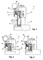
- An electrical connector designated overall by the reference numeral 1 comprises a first plug connection part 2 and a second plug connection part 3.
- the plug connection parts 2, 3 each have a chamber housing for accommodating respectively complementary contact elements.
- the chamber housing is designed as a receptacle housing for receiving female contact elements
- the chamber housing of the connector part 3 is designed as a connector housing for receiving male contact elements.
- the connector part 3 is part of an aggregate, not shown.
- the connector part 2 forms the free end of a connection cable set for connecting the unit.
- the connector part 3 comprises a collar 4, on the outside a locking cam 5 is arranged abragend.
- the locking cam 5 has an executed to the connector part 2 2 bevel and a locking surface 7.
- the connector part 2 comprises a molded over a meandering shaped connecting member 8 locking hooks 9, the hook portion 10 is formed as a locking element for locking the two connector parts 2, 3 for engaging behind the locking cam 5 of the connector part 3.
- Part of the connector part 2 is further a spring tongue 11, which is supported on the back of the latching hook 9, and by which a contact pressure of the hook member 10 is provided on the outer surface of the collar 4 of the connector part.
- the latching hook 9 is guided with two diametrically opposite bearing journals 12, which may well be designed as a journal approaches, in each case a two pin positions permitting bearing eye 13.
- the bearing pins 12 are in a first pin position within the bearing eyes 13.
- the latching hooks 9 continues in an upwardly extending from the bearing pin 12 actuating lever 14. By pivoting the actuating lever 14 in the counterclockwise direction, the bearing pins 12 can be brought from its first position shown in Figure 1 in a second pin position of the bearing eyes 13.
- Figure 1 shows the two connector parts 2, 3 in a Georgia Montmony styrene-maleic anhydride-styrene-maleic anhydride-styrene-styrene-styrene-maleic anhydride-styrene-styrene-styrene-styrene-styrene-styrene-styrene-styrene-sstyrenetyl-styl-styrenetyrene-styrene-styrene-styrene-styrene-styrene-styrene-styrene-styrene-styrene-styrene-styrene-styrene-styrene-styrene-styrene-styrene-styrene-styrene-styrene-st
- the latching hook 9 is pivoted with its hook portion 10 about a virtual axis of rotation, wherein in this pivoting a not irrelevant vectorial portion is directed against the joining direction of the two connector parts 2, 3, so that when exercising this movement the two connector parts 2, 3 are moved toward each other until, in the situation shown in Figure 3 between the two connector parts 2, 3 no axial play longer exists.
- the aforementioned axis of rotation is in the illustrated embodiment approximately in the region of the support of the latching hook 9 on the spring tongue eleventh
- the compliant design of the connecting member 8 is useful to accommodate especially manufacturing tolerances readily, so that it is ensured in any case that the force exerted by moving the latching hook 9 stroke of the hook portion 10 also formed by unfavorable manufacturing tolerances larger Axial play is eliminated.
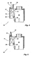
- Figure 4 shows another connector 16 with two connector parts 17, 18.
- a elimination of the axial play also takes place in this connector 16 in an analogous manner, as to the connector 1 of Figures 1 to 3 described.
- the connector part 17 has a likewise integrally formed via a connecting member 19 latch hook 20.
- Figure 4 shows the two connector parts 17, 18 after their joining, between both elements still axial play is present.
- the plug-in connection part 17 comprises a shoulder 21, which is delimited by an edge bead 22 towards the latching hook 20.
- the latching hook 20 also has like the latching hook 9 via an actuating lever 23 which carries on one side extension on the underside one or more support cams 24.
Landscapes
- Details Of Connecting Devices For Male And Female Coupling (AREA)
Description
- Die Erfindung betrifft einen elektrischen Steckverbinder, umfassend ein erstes Steckverbindungsteil mit einem Kammergehäuse zur Aufnahme von ersten elektrischen Kontaktelementen und ein zweites Steckverbindungsteil mit einem Kammergehäuse zur Aufnahme von zweiten, komplementär zu den Kontaktelementen des ersten Steckverbindungsteils ausgebildeten Kontaktelementen, wobei einem der beiden Steckverbindungsteile ein Rastelement und dem anderen Steckverbindungsteil ein Rastnocken zugeordnet ist und das Rastelement bei miteinander verbundenen Steckverbindungsteilen als Abzugssicherung den Rastnocken des anderen Steckverbindungsteils hintergreift.
- Ein solcher Steckverbinder ist aus der
DE 101 586 25 bekannt, welcher als nächstliegender Stand der Technik angesehen wird. - Derartige elektrische Steckverbinder werden unter anderem im Automotiv-Bereich eingesetzt, beispielsweise zum Kontaktieren eines Aktors zum Betätigen der Drosselkappe eines Verbrennungsmotors. Eines der beiden Steckverbindungsteile ist ein Steckhülsengehäuse, während das andere Steckverbindungsteil ein Steckergehäuse ist. Das Steckergehäuse verfügt über einen Steckerkragen zum Schutze der innerhalb des Kragens angeordneten Steckerkontakte. Das Steckergehäuse ist bei der vorbeschriebenen Ausgestaltung fest installiert; das Steckhülsengehäuse befindet sich an dem freien Ende eines Anschlusskabelsatzes. Das Steckhülsengehäuse verfügt über einen Rasthaken, dessen von einer Federzunge abgewinkelter Abschnitt das eigentliche Rastelement darstellt. Der Rasthaken selbst ist angeformt an das Steckhülsengehäuse, so dass die notwendige Elastizität des Rasthakens aus seiner Materialelastizität resultiert. Das Steckergehäuse trägt außenseitig einen Rastnocken, der nach bestimmungsgemäßem Verbinden der beiden Steckverbindungsteile von dem Rastelement des Rasthakens hintergriffen wird. Dieses dient als Abzugssicherung. Beim Aufstecken des Steckhülsengehäuses auf das Steckergehäuse wird das Rastelement gegen die aus dem Rasthaken resultierende Materialelastizität nach außen weggedrückt. Dieses schnappt nach Passieren des Rastnockens zurück, so dass sich das Rastelement dann in seiner bestimmungsgemäßen, den Rastnocken hintergreifenden Verriegelungsstellung befindet. Damit ein solches Zurückschnappen erfolgt, ist es notwendig, das Rastelement des Rasthakens und den Rastnocken mit einem zwischen diesen Elementen befindlichen Axialspiel zu konzipieren. Dieses notwendige Axialspiel kann sich jedoch nachteilig auf die elektrische Verbindung zwischen den Kontaktelementen des einen Steckverbindungsteils mit denjenigen des anderen Steckverbindungsteils auswirken, insbesondere wenn auf den Steckverbinder Vibrationen einwirken, wie dieses bei einer Anordnung des Steckverbinders unmittelbar an der Verbrennungsmaschine der Fall ist. Beeinträchtigungen können vor allem bei einer Übertragung nur geringer oder geringster Ströme eintreten.
- Im Hinblick auf die bei der Herstellung der beiden Steckverbindungsteile in Kauf zu nehmenden Toleranzen muss zudem das notwendige Axialspiel so bemessen sein, dass auch bei ungünstigen Herstellungstoleranzen in jedem Fall ein Axialspiel zwischen den beiden Steckverbindungsteilen zum Gewährleisten eines bestimmungsgemäßen Einrastens des Rastelements vorhanden ist.
- Ausgehend von diesem diskutierten Stand der Technik liegt der Erfindung daher die Aufgabe zugrunde, einen eingangs genannten, gattungsgemäßen Steckverbinder dergestalt weiterzubilden, dass die hinsichtlich des Axialspiels bei dem gewürdigten vorbekannten Stand der Technik aufgezeigten Nachteile vermieden sind.
- Diese Aufgabe wird erfindungsgemäß durch einen elektrischen Steckverbinder gelöst, bei dem das Rastelement derart verstellbar an dem einen Steckverbindungsteil angeschlossen ist, dass dieses in seiner einen Stellung mit dem notwendigen Axialspiel zum Gewährleisten eines bestimmungsgemäßen Einrastens hinter den Rastnocken angeordnet ist und sich in seiner anderen Stellung in einer Spannstellung befindet, in der das Rastelement gegenüber seiner vorgenannten Stellung entgegen der Fügerichtung zum Fügen der beiden Steckverbindungsteile unter Beibehaltung der Verrastungsanordnung mit dem Rastnocken des anderen Steckverbindungsteils zum Beseitigen des Axialspiels bewegt worden ist.
- Bei diesem Steckverbinder ist das Rastelement des einen Steckverbindungsteils zusätzlich zu seiner Rastbewegung zum Hintergreifen des Rastnockens des anderen Steckverbindungsteils aus einer ersten Stellung, in der das Rastelement in seine den Rastnocken hintergreifende Stellung gebracht wird, in eine zweite Stellung bewegbar, die eine Spannstellung darstellt. In der Spannstellung des Rastelementes ist dieses unter Beibehaltung der Verrastungsanordnung mit dem Rastnocken entgegen der Fügerichtung zum Fügen der beiden Steckverbindungsteile bewegt worden. Das Bewegen des Rastelementes in dieser Richtung nach Einbringen desselben in seine Verrastungsanordnung beseitigt das zwischen den beiden Steckverbindungsteilen bestehende Axialspiel. Dabei steht zweckmäßigerweise das Rastelement in seiner Spannstellung unter einer gewissen Vorspannung, so dass die beiden Steckverbindungsteile sicher spielfrei verbunden sind. Das Bewegen des Rastelementes entgegen der Fügerichtung kann durch eine translatorische Bewegung oder auch durch eine Verschwenkbewegung des Rastelementes erfolgen. Im letzteren Fall bewirkt der entgegen der Fügerichtung gerichtete vektorielle Anteil einer solchen Verschwenkbewegung die bestimmungsgemäße Axialspielbeseitigung.
- Zweckmäßigerweise ist das Rastelement des einen Steckverbindungsteils Teil eines Rasthakens, der mittels eines entgegen der Fügerichtung elastisch reagierenden Verbindungsgliedes an das den Rasthaken tragende Steckverbindungsteil angeschlossen, beispielsweise angeformt ist. Der Rasthaken stützt sich in seiner Spannstellung an einem Widerlager des Steckverbindungsteils ab. Dieses Widerlager kann durch einen Absatz gebildet sein. Zweckmäßigerweise ist dieser Widerlagerabsatz durch einen Randwulst begrenzt, über den eine dem Rasthaken zugeordnete Stütznocke bewegt wird, um sich auf dem Widerlagerabsatz abzustützen. Der Rasthaken ist dann in seiner Spannstellung verrastet gehalten.
- Gemäß einer weiteren Ausgestaltung ist vorgesehen, dass der Rasthaken über Lagerzapfen verfügt, die in jeweils ein zwei Zapfenpositionen zulassendes Auge des Steckverbindungsteils eingreifen. Die beiden Zapfenpositionen sind durch einen Totpunkt voneinander getrennt, so dass in beiden Zapfenpositionen der Rasthaken stabil gehalten ist. Die beiden Zapfenpositionen sind dergestalt zueinander angeordnet, dass beim Bewegen des Rasthakens mit seinen Lagerzapfen von derjenigen Zapfenposition, in der die beiden Steckverbindungsteile bestimmungsgemäß zusammengefügt werden, in diejenige Zapfenposition, die der Spannstellung des Rasthakens entspricht, das eigentliche Rastelement des Rasthakens entgegen der Fügerichtung bewegt worden ist, wobei durch diese Bewegung die beiden Steckverbindungsteile relativ zueinander unter Beseitigung des Axialspiels bewegt worden sind. Das Verbindungsglied bei einer solchen Ausgestaltung kann eine Mäanderform aufweisen und sich etwa parallel zur Längserstreckung des Rasthakens erstrecken. Durch die Mäanderform ist das Verbindungsglied entgegen der Fügerichtung der beiden Steckverbindungsteile elastisch, so dass unabhängig von dem tatsächlich vorhandenen Axialspiel zwischen den beiden Steckverbindungsteilen die Toleranzen in diesem Verbindungsglied aufgefangen werden können.
- Nachfolgend ist die Erfindung anhand von Ausführungsbeispielen unter Bezugnahme auf die beigefügten Figuren beschrieben. Es zeigen:
- Fig. 1:
- eine schematisierte zum Teil geschnittene Darstellung eines Steckverbinders mit zwei Steckverbindungsteilen beim Zusammenführen der beiden Steckverbindungsteile,
- Fig. 2:
- die beiden zusammengeführten und gefügten Steckverbindungsteile der Figur 1 mit eingreifender Abzugssicherung,
- Fig. 3:
- die Anordnung der Figur 2 nach Beseitigen eines Axialspiels zwischen den beiden Steckverbindungsteilen,
- Fig. 4:
- zwei miteinander gefügte Steckverbindungsteile eines weiteren Steckverbinders vor dem Beseitigen eines Axialspiels und
- Fig. 5:
- die Anordnung der Figur 4 nach Beseitigen des zwischen des beiden Steckverbindungsteils befindlichen Axialspiels.
- Ein insgesamt mit den Bezugszeichen 1 bezeichneter elektrischer Steckverbinder umfasst ein erstes Steckverbindungsteil 2 und ein zweites Steckverbindungsteil 3. Die Steckverbindungsteile 2, 3 weisen jeweils ein Kammergehäuse zur Aufnahme von jeweils komplementär ausgebildeten Kontaktelementen auf. Bei dem Steckverbindungsteil 2 ist das Kammergehäuse als Steckhülsengehäuse zur Aufnahme von weiblichen Kontaktelementen ausgebildet, während das Kammergehäuse des Steckverbindungsteils 3 als Steckergehäuse zur Aufnahme von männlichen Kontaktelementen konzipiert ist. Das Steckverbindungsteil 3 ist Teil eines nicht näher dargestellten Aggregates. Das Steckverbindungsteil 2 bildet das freie Ende eines Anschlusskabelsatzes zum Anschließen des Aggregates.
- Das Steckverbindungsteil 3 umfasst einen Kragen 4, an dem außenseitig eine Rastnocke 5 abragend angeordnet ist. Die Rastnocke 5 weist eine zu dem Steckverbindungsteil 2 hingerichtete Stellschräge 6 und eine Riegelfläche 7 auf.
- Das Steckverbindungsteil 2 umfasst einen über ein mäanderförmig ausgebildetes Verbindungsglied 8 angeformten Rasthaken 9, dessen Hakenabschnitt 10 als Rastelement zum Verriegeln der beiden Steckverbindungsteile 2, 3 zum Hintergreifen der Rastnocke 5 des Steckverbindungsteils 3 ausgebildet ist. Teil des Steckverbindungsteils 2 ist ferner eine Federzunge 11, die sich an der Rückseite des Rasthakens 9 abstützt, und durch die ein Anpressdruck des Hakenelementes 10 auf die äußere Oberfläche des Kragens 4 des Steckverbindungsteils bereitgestellt wird. Der Rasthaken 9 ist mit zwei einander diametral gegenüberliegenden Lagerzapfen 12, die durchaus auch als Zapfenansätze ausgebildet sein können, in jeweils einem zwei Zapfenpositionen zulassenden Lagerauge 13 geführt. In Figur 1 befinden sich die Lagerzapfen 12 in einer ersten Zapfenposition innerhalb der Lageraugen 13. Der Rasthaken 9 setzt sich in einem sich von den Lagerzapfen 12 nach oben erstreckenden Betätigungshebel 14 fort. Durch Verschwenken des Betätigungshebels 14 entgegen dem Uhrzeigersinn können die Lagerzapfen 12 aus ihrer in Figur 1 gezeigten ersten Stellung in eine zweite Zapfenstellung der Lageraugen 13 gebracht werden.
- Figur 1 zeigt die beiden Steckverbindungsteile 2, 3 bei einer Zusammenführbewegung, bei der der Kragen 4 des Steckverbindungsteils 3 bereits in eine entsprechende Kragennut des Steckverbindungsteils 2 eingeführt worden ist. Beide Steckverbindungsteile 2, 3 haben sich somit gefunden. Bei einem weiteren Zusammenführen der beiden Steckverbindungsteile 2, 3 wird der Hakenabschnitt 10 des Rasthakens 9 der äußeren Oberfläche des Kragens 4 der Steckverbindungsleiste 3 entlang bewegt. Bei dieser weiteren aufeinander zugerichteten Bewegung der beiden Steckverbindungsteile 2, 3 werden diese zusammengefügt, wobei die elektrischen Kontaktelemente des Steckverbindungsteils 3 mit denjenigen des Steckverbindungsteils 2 in Eingriff gestellt werden. Bei diesem Fügevorgang wird der Rasthaken 9 mit seinem Hakenabschnitt 10 über die Stellschräge 6 der Rastnocke 5 bewegt und rastet hinter der Rastnocke 5, beaufschlagt durch die Kraft der Federzunge, spürbar und hörbar ein. Diese Stellung ist in Figur 2 dargestellt. Damit der Rasthaken 9 mit seinem Hakenabschnitt 10 bestimmungsgemäß hinter der Rastnocke 5 einrasten bzw. einschnappen kann, müssen die beiden Steckverbindungsteile 2, 3 mit einem gewissen Axialspiel zueinander angeordnet sein. Das Axialspiel ist in Figur 2 mit dem Bezugszeichen A gekennzeichnet.
- In Figur 2 befindet sich der Rasthaken 9 noch in seiner zu Figur 1 gezeigten Stellung, bei der die Lagerzapfen 12 in die erste Zapfenposition der Lageraugen 13 eingreifen. Wie aus Figur 2 ersichtlich, hintergreift der Hakenabschnitt 10 die Rastnocke 5. Zum Beseitigen des zwischen den beiden Steckverbindungsteilen 2, 3 verbliebenen Axialspiels A wird nunmehr der Betätigungshebel 14 entgegen dem Uhrzeigersinn - wie durch den Pfeil in Figur 2 angedeutet - verschwenkt, damit auf diese Weise die Lagerzapfen 12 in die zweite Zapfenposition der Lageraugen 13 gebracht werden. Diese Situation ist in Figur 3 wiedergegeben. Zwischen den beiden Zapfenpositionen der Lageraugen 13 befindet sich ein Wulst 15, durch den ein Totpunkt bereitgestellt ist, so dass der Rasthaken 9 in beiden Positionen stabil in den Lageraugen 13 gehalten ist. Durch Bewegen des Betätigungshebels 14 in der beschriebenen Weise wird der Rasthaken 9 mit seinem Hakenabschnitt 10 um eine virtuelle Drehachse verschwenkt, wobei bei dieser Verschwenkbewegung ein nicht unmaßgeblicher vektorieller Anteil entgegen der Fügerichtung der beiden Steckverbindungsteile 2, 3 gerichtet ist, so dass beim Ausüben dieser Bewegung die beiden Steckverbindungsteile 2, 3 aufeinander zubewegt werden, bis in der in Figur 3 gezeigten Situation zwischen den beiden Steckverbindungsteilen 2, 3 kein Axialspiel mehr vorhanden ist. Die genannte Drehachse befindet sich bei dem dargestellten Ausführungsbeispiel etwa im Bereich der Abstützung des Rasthakens 9 an der Federzunge 11.
- Bei diesem Ausführungsbeispiel ist die nachgiebige Ausbildung des Verbindungsgliedes 8 zweckmäßig, um insbesondere auch herstellungsbedingte Toleranzen ohne weiteres aufnehmen zu können, so dass in jedem Fall sichergestellt ist, dass der durch Bewegen des Rasthakens 9 ausgeübte Hub des Hakenabschnittes 10 auch ein durch ungünstige Herstellungstoleranzen gebildetes größeres Axialspiel beseitigt wird.
- Figur 4 zeigt einen weiteren Steckverbinder 16 mit zwei Steckverbindungsteilen 17, 18. Prinzipiell erfolgt eine Beseitigung des Axialspiels auch bei diesem Steckverbinder 16 in analoger Weise, wie zu dem Steckverbinder 1 der Figuren 1 bis 3 beschrieben. Bei dem Steckverbinder 16 verfügt das Steckverbindungsteil 17 über einen ebenfalls über ein Verbindungsglied 19 angeformten Rasthaken 20. Figur 4 zeigt die beiden Steckverbindungsteile 17, 18 nach ihrem Fügen, wobei zwischen beiden Elementen noch Axialspiel vorhanden ist.
- Das Steckverbindungsteil 17 umfasst einen Absatz 21, der zum Rasthaken 20 hin durch einen Randwulst 22 begrenzt ist. Der Rasthaken 20 verfügt ebenfalls wie der Rasthaken 9 über einen Betätigungshebel 23, der an einem seitlichen Fortsatz unterseitig einen oder mehrere Stütznocken 24 trägt.
- Durch Verschwenken des Betätigungshebels 19 wird der Rasthaken 20 mit verschwenkt, wobei durch das Hakenelement 25 des Rasthakens 20 ein entgegen der Fügerichtung der beiden Steckverbindungsteile 17, 18 gerichteter Hub ausgeübt wird, so dass auf diese Weise ein zwischen den beiden Steckverbindungsteilen 17, 18 verbliebendes Axialspiel beseitigt wird. Diese Stellung ist zu diesem Ausführungsbeispiel in Figur 5 gezeigt. Der Betätigungshebel 23 stützt sich mit seinem Stütznocken 24 in dem Absatz 21 ab und ist in dieser Position durch den Randwulst 22 gesichert.
-
- 1
- Steckverbinder
- 2
- Steckverbindungsteil
- 3
- Steckverbindungsteil
- 4
- Kragen
- 5
- Rastnocken
- 6
- Stellschräge
- 7
- Riegelfläche
- 8
- Verbindungsglied
- 9
- Rasthaken
- 10
- Hakenabschnitt
- 11
- Federzunge
- 12
- Lagerzapfen
- 13
- Lagerauge
- 14
- Betätigungshebel
- 15
- Wulst
- 16
- Steckverbinder
- 17
- Steckverbindungsteil
- 18
- Steckverbindungsteil
- 19
- Verbindungsglied
- 20
- Rasthaken
- 21
- Absatz
- 22
- Randwulst
- 23
- Betätigungshebel
- 24
- Stütznocken
- 25
- Hakenelement
- A
- Axialspiel
Claims (7)
- Elektrischer Steckverbinder, umfassend ein erstes Steckverbindungsteil (2, 17) mit einem Kammergehäuse zur Aufnahme von ersten elektrischen Kontaktelementen und ein zweites Steckverbindungsteil (3, 18) mit einem Kammergehäuse zur Aufnahme von zweiten, komplementär zu den Kontaktelementen des ersten Steckverbindungsteils (2, 17) ausgebildeten Kontaktelementen, wobei einem der beiden Steckverbindungsteile (2, 17) ein Rastelement (10, 25) und dem anderen Steckverbindungsteil (3, 18) ein Rastnocken (5) zugeordnet ist und das Rastelement (10, 25) bei miteinander verbundenen Steckverbindungsteilen (2, 3; 17, 18) als Abzugssicherung den Rastnocken (5) des anderen Steckverbindungsteils (3, 18) hintergreift, dadurch gekennzeichnet, dass das Rastelement (10, 25) derart verstellbar an dem einen Steckverbindungsteil (2, 17) angeschlossen ist, dass dieses in seiner einen Stellung mit dem notwendigen Axialspiel (A) zum Gewährleisten eines bestimmungsgemäßen Einrastens hinter den Rastnocken (5) angeordnet ist und sich in seiner anderen Stellung in einer Spannstellung befindet, in der das Rastelement (10, 25) gegenüber seiner vorgenannten Stellung entgegen der Fügerichtung zum Fügen der beiden Steckverbindungsteile (2, 3; 17, 18) unter Beibehaltung der Verrastungsanordnung mit dem Rastnocken (5) des anderen Steckverbindungsteils (3, 18) zum Beseitigen des Axialspiels bewegt worden ist.
- Steckverbinder nach Anspruch 1, dadurch gekennzeichnet, dass das Rastelement (10, 25) Teil eines an dem einen Steckverbindungsteil (2, 17) mit einem entgegen der Fügerichtung elastisch reagierenden Verbindungsglied (8, 19) gehaltenen Rasthaken (9, 20) ist, und dass sich der Rasthaken (9, 20) in seiner Spannstellung an einem Widerlager des den Rasthaken (9, 20) tragenden Steckverbindungsteils (2, 17) abstützt.
- Steckverbinder nach Anspruch 2, dadurch gekennzeichnet, dass das Widerlager durch einen durch einen Randwulst (22) begrenzten Absatz (21) gebildet ist.
- Steckverbinder nach Anspruch 2, dadurch gekennzeichnet, dass der Rasthaken (9) mit zwei einander diametral gegenüberliegenden Lagerzapfen (12) in jeweils ein zwei Zapfenpositionen zulassendes Auge (13) eingreift, wobei beide Zapfenpositionen jedes Auges (13) durch einen Totpunkt voneinander getrennt sind.
- Steckverbinder nach einem der Ansprüche 2 bis 4, dadurch gekennzeichnet, dass das Verbindungsglied (9) eine Mäanderform aufweist und sich etwa parallel zur Längserstreckung des das Rastelement (10) tragenden Rasthakens (9) erstreckt.
- Steckverbinder nach einem der Ansprüche 1 bis 5, dadurch gekennzeichnet, dass dem das Rastelement (10) tragenden Steckverbindungsteil (2) ein auf das Rastelement (10) in Richtung seiner Verriegelungsstellung zum Hintergreifen des Rastnockens (5) des anderen Steckverbindungsteils (3) wirkendes Federelement (11) zugeordnet ist.
- Steckverbinder nach einem der Ansprüche 1 bis 6, dadurch gekennzeichnet, dass das Rastelement (10) tragende Steckverbindungsteil (2) ein Steckhülsengehäuse und das den Rastnocken (5) tragende Steckverbindungsteil (3) ein Steckergehäuse mit einem Kragen (4) ist, an dessen Außenseite der Rastnocken (5) angeformt ist.
Applications Claiming Priority (2)
| Application Number | Priority Date | Filing Date | Title |
|---|---|---|---|
| DE10331935A DE10331935A1 (de) | 2003-07-15 | 2003-07-15 | Elektrischer Steckverbinder |
| PCT/EP2004/007704 WO2005008844A1 (de) | 2003-07-15 | 2004-07-13 | Elektrischer steckverbinder |
Publications (2)
| Publication Number | Publication Date |
|---|---|
| EP1645016A1 EP1645016A1 (de) | 2006-04-12 |
| EP1645016B1 true EP1645016B1 (de) | 2007-10-31 |
Family
ID=33560102
Family Applications (1)
| Application Number | Title | Priority Date | Filing Date |
|---|---|---|---|
| EP04740950A Expired - Lifetime EP1645016B1 (de) | 2003-07-15 | 2004-07-13 | Elektrischer steckverbinder |
Country Status (6)
| Country | Link |
|---|---|
| US (1) | US6962502B2 (de) |
| EP (1) | EP1645016B1 (de) |
| AT (1) | ATE377273T1 (de) |
| DE (2) | DE10331935A1 (de) |
| ES (1) | ES2295878T3 (de) |
| WO (1) | WO2005008844A1 (de) |
Families Citing this family (4)
| Publication number | Priority date | Publication date | Assignee | Title |
|---|---|---|---|---|
| DE102005025769B3 (de) * | 2005-06-04 | 2006-09-21 | Harting Electric Gmbh & Co. Kg | Verriegelungseinrichtung für Steckverbinder |
| US7601019B2 (en) * | 2007-06-22 | 2009-10-13 | Delphi Technologies, Inc. | Electrical connection system |
| JP5524725B2 (ja) * | 2010-06-08 | 2014-06-18 | 株式会社東海理化電機製作所 | 給電プラグのロック装置 |
| CN103178401A (zh) * | 2011-12-21 | 2013-06-26 | 鸿富锦精密工业(深圳)有限公司 | 连接器插头 |
Family Cites Families (11)
| Publication number | Priority date | Publication date | Assignee | Title |
|---|---|---|---|---|
| US4714433A (en) * | 1987-01-21 | 1987-12-22 | General Motors Corporation | Electrical connector with position assurance and double lock |
| DE3727200A1 (de) * | 1987-08-14 | 1989-02-23 | Spinner Georg | Sender/antennen-feld |
| JPH0454161U (de) * | 1990-09-14 | 1992-05-08 | ||
| JPH0740317Y2 (ja) * | 1990-11-30 | 1995-09-13 | 山一電機工業株式会社 | ラッチ付コネクタ |
| DE4243268A1 (de) * | 1992-12-19 | 1994-06-23 | Bosch Gmbh Robert | Lösbare Steckverbindung |
| JP3067468B2 (ja) * | 1993-04-27 | 2000-07-17 | 住友電装株式会社 | コネクタ |
| US5795175A (en) * | 1995-02-21 | 1998-08-18 | Aero Electric Connector System, Inc. | Rectangular hand-mount connector |
| DE29517358U1 (de) * | 1995-11-02 | 1996-01-11 | Harting Elektronik Gmbh, 32339 Espelkamp | Koaxial Steckverbindung |
| DE19961708C1 (de) * | 1999-12-21 | 2001-08-09 | Ilme Spa | Verriegelungsvorrichtung für zwei Steckverbinder enthaltende Gehäuseteile |
| JP2002170629A (ja) * | 2000-12-01 | 2002-06-14 | Sumitomo Wiring Syst Ltd | コネクタ |
| EP1780839B1 (de) * | 2002-01-30 | 2012-03-21 | Sumitomo Wiring Systems, Ltd. | Verbinder |
-
2003
- 2003-07-15 DE DE10331935A patent/DE10331935A1/de not_active Withdrawn
-
2004
- 2004-07-13 AT AT04740950T patent/ATE377273T1/de not_active IP Right Cessation
- 2004-07-13 EP EP04740950A patent/EP1645016B1/de not_active Expired - Lifetime
- 2004-07-13 DE DE502004005373T patent/DE502004005373D1/de not_active Expired - Lifetime
- 2004-07-13 ES ES04740950T patent/ES2295878T3/es not_active Expired - Lifetime
- 2004-07-13 WO PCT/EP2004/007704 patent/WO2005008844A1/de not_active Ceased
-
2005
- 2005-01-28 US US11/045,890 patent/US6962502B2/en not_active Expired - Fee Related
Also Published As
| Publication number | Publication date |
|---|---|
| US20050130481A1 (en) | 2005-06-16 |
| EP1645016A1 (de) | 2006-04-12 |
| WO2005008844A1 (de) | 2005-01-27 |
| ATE377273T1 (de) | 2007-11-15 |
| US6962502B2 (en) | 2005-11-08 |
| DE10331935A1 (de) | 2005-02-03 |
| ES2295878T3 (es) | 2008-04-16 |
| DE502004005373D1 (de) | 2007-12-13 |
Similar Documents
| Publication | Publication Date | Title |
|---|---|---|
| DE69516096T2 (de) | Verbinder mit einer vorderseitigen Kontaktlagesicherung | |
| DE112017001349B4 (de) | Verbindersystem mit Verbinderpositionsgewährleistung | |
| DE69530364T2 (de) | Elektrischer Steckverbinder mit verbessertem Nockensystem | |
| DE112016006292B4 (de) | Verbindersystem mit Verbinderpositionsgewährleistung | |
| DE69600063T2 (de) | Verbinder mit Sekundärverriegelung und Kupplungsvorrichtung | |
| EP2564473B1 (de) | Elektrische steckverbindung insbesondere rundsteckverbindung | |
| DE69700960T2 (de) | Verriegelungsvorrichtung für einen steckverbinder | |
| EP4066325B1 (de) | Sekundärverriegelungsvorrichtung | |
| EP1662620A2 (de) | Elektrische Steckverbindung | |
| DE69412380T2 (de) | Vibrationsbeständiges elektrisches Verbindergehäuse | |
| DE68912184T2 (de) | Steckeraufbau mit beweglicher Schutzverkleidung. | |
| DE112011102284T5 (de) | Hebelsteckverbinder | |
| EP2769441A1 (de) | Steckverbinder | |
| DE60104354T2 (de) | Steckverbinder | |
| DE112021001561T5 (de) | Schwimmender Wannenstecker und Leiterplatten-Anordnung | |
| DE69310439T2 (de) | Verriegelbarer elektrischer Verbinderanordnung | |
| EP1645016B1 (de) | Elektrischer steckverbinder | |
| DE19525257C2 (de) | Elektrische Steckverbindung mit Endlagen-Verriegelung | |
| DE69513317T2 (de) | Gehäuse zum Sichern einer elektrischen Verbindung | |
| DE60006331T2 (de) | Steckvorrichtungssystem zur Verhinderung einer falschen Kupplung | |
| EP1463160B1 (de) | Stecker mit Schieber zum Verbinden mit einer Steckbuchse | |
| DE69026782T2 (de) | Verriegelungsvorrichtung für Verbinder | |
| DE102006016909B4 (de) | Stecker mit einem Verriegelungshebel | |
| DE19513583C2 (de) | Elektrische Kontaktanordnung | |
| DE202020005530U1 (de) | Primärverriegelung |
Legal Events
| Date | Code | Title | Description |
|---|---|---|---|
| PUAI | Public reference made under article 153(3) epc to a published international application that has entered the european phase |
Free format text: ORIGINAL CODE: 0009012 |
|
| 17P | Request for examination filed |
Effective date: 20050113 |
|
| AK | Designated contracting states |
Kind code of ref document: A1 Designated state(s): AT BE BG CH CY CZ DE DK EE ES FI FR GB GR HU IE IT LI LU MC NL PL PT RO SE SI SK TR |
|
| DAX | Request for extension of the european patent (deleted) | ||
| GRAP | Despatch of communication of intention to grant a patent |
Free format text: ORIGINAL CODE: EPIDOSNIGR1 |
|
| GRAS | Grant fee paid |
Free format text: ORIGINAL CODE: EPIDOSNIGR3 |
|
| GRAA | (expected) grant |
Free format text: ORIGINAL CODE: 0009210 |
|
| AK | Designated contracting states |
Kind code of ref document: B1 Designated state(s): AT BE BG CH CY CZ DE DK EE ES FI FR GB GR HU IE IT LI LU MC NL PL PT RO SE SI SK TR |
|
| REG | Reference to a national code |
Ref country code: GB Ref legal event code: FG4D Free format text: NOT ENGLISH |
|
| REG | Reference to a national code |
Ref country code: IE Ref legal event code: FG4D Free format text: LANGUAGE OF EP DOCUMENT: GERMAN |
|
| REG | Reference to a national code |
Ref country code: CH Ref legal event code: EP |
|
| REF | Corresponds to: |
Ref document number: 502004005373 Country of ref document: DE Date of ref document: 20071213 Kind code of ref document: P |
|
| GBT | Gb: translation of ep patent filed (gb section 77(6)(a)/1977) |
Effective date: 20080109 |
|
| NLV1 | Nl: lapsed or annulled due to failure to fulfill the requirements of art. 29p and 29m of the patents act | ||
| REG | Reference to a national code |
Ref country code: ES Ref legal event code: FG2A Ref document number: 2295878 Country of ref document: ES Kind code of ref document: T3 |
|
| PG25 | Lapsed in a contracting state [announced via postgrant information from national office to epo] |
Ref country code: NL Free format text: LAPSE BECAUSE OF FAILURE TO SUBMIT A TRANSLATION OF THE DESCRIPTION OR TO PAY THE FEE WITHIN THE PRESCRIBED TIME-LIMIT Effective date: 20071031 Ref country code: SE Free format text: LAPSE BECAUSE OF FAILURE TO SUBMIT A TRANSLATION OF THE DESCRIPTION OR TO PAY THE FEE WITHIN THE PRESCRIBED TIME-LIMIT Effective date: 20080131 |
|
| PG25 | Lapsed in a contracting state [announced via postgrant information from national office to epo] |
Ref country code: BG Free format text: LAPSE BECAUSE OF FAILURE TO SUBMIT A TRANSLATION OF THE DESCRIPTION OR TO PAY THE FEE WITHIN THE PRESCRIBED TIME-LIMIT Effective date: 20080131 Ref country code: SI Free format text: LAPSE BECAUSE OF FAILURE TO SUBMIT A TRANSLATION OF THE DESCRIPTION OR TO PAY THE FEE WITHIN THE PRESCRIBED TIME-LIMIT Effective date: 20071031 Ref country code: PL Free format text: LAPSE BECAUSE OF FAILURE TO SUBMIT A TRANSLATION OF THE DESCRIPTION OR TO PAY THE FEE WITHIN THE PRESCRIBED TIME-LIMIT Effective date: 20071031 Ref country code: PT Free format text: LAPSE BECAUSE OF FAILURE TO SUBMIT A TRANSLATION OF THE DESCRIPTION OR TO PAY THE FEE WITHIN THE PRESCRIBED TIME-LIMIT Effective date: 20080331 |
|
| REG | Reference to a national code |
Ref country code: IE Ref legal event code: FD4D |
|
| ET | Fr: translation filed | ||
| PG25 | Lapsed in a contracting state [announced via postgrant information from national office to epo] |
Ref country code: DK Free format text: LAPSE BECAUSE OF FAILURE TO SUBMIT A TRANSLATION OF THE DESCRIPTION OR TO PAY THE FEE WITHIN THE PRESCRIBED TIME-LIMIT Effective date: 20071031 Ref country code: CZ Free format text: LAPSE BECAUSE OF FAILURE TO SUBMIT A TRANSLATION OF THE DESCRIPTION OR TO PAY THE FEE WITHIN THE PRESCRIBED TIME-LIMIT Effective date: 20071031 |
|
| PG25 | Lapsed in a contracting state [announced via postgrant information from national office to epo] |
Ref country code: SK Free format text: LAPSE BECAUSE OF FAILURE TO SUBMIT A TRANSLATION OF THE DESCRIPTION OR TO PAY THE FEE WITHIN THE PRESCRIBED TIME-LIMIT Effective date: 20071031 Ref country code: RO Free format text: LAPSE BECAUSE OF FAILURE TO SUBMIT A TRANSLATION OF THE DESCRIPTION OR TO PAY THE FEE WITHIN THE PRESCRIBED TIME-LIMIT Effective date: 20071031 |
|
| PLBE | No opposition filed within time limit |
Free format text: ORIGINAL CODE: 0009261 |
|
| STAA | Information on the status of an ep patent application or granted ep patent |
Free format text: STATUS: NO OPPOSITION FILED WITHIN TIME LIMIT |
|
| 26N | No opposition filed |
Effective date: 20080801 |
|
| PG25 | Lapsed in a contracting state [announced via postgrant information from national office to epo] |
Ref country code: IE Free format text: LAPSE BECAUSE OF FAILURE TO SUBMIT A TRANSLATION OF THE DESCRIPTION OR TO PAY THE FEE WITHIN THE PRESCRIBED TIME-LIMIT Effective date: 20071031 |
|
| PG25 | Lapsed in a contracting state [announced via postgrant information from national office to epo] |
Ref country code: GR Free format text: LAPSE BECAUSE OF FAILURE TO SUBMIT A TRANSLATION OF THE DESCRIPTION OR TO PAY THE FEE WITHIN THE PRESCRIBED TIME-LIMIT Effective date: 20080201 |
|
| PG25 | Lapsed in a contracting state [announced via postgrant information from national office to epo] |
Ref country code: FI Free format text: LAPSE BECAUSE OF FAILURE TO SUBMIT A TRANSLATION OF THE DESCRIPTION OR TO PAY THE FEE WITHIN THE PRESCRIBED TIME-LIMIT Effective date: 20071031 |
|
| REG | Reference to a national code |
Ref country code: CH Ref legal event code: PL |
|
| PG25 | Lapsed in a contracting state [announced via postgrant information from national office to epo] |
Ref country code: MC Free format text: LAPSE BECAUSE OF NON-PAYMENT OF DUE FEES Effective date: 20080731 |
|
| PG25 | Lapsed in a contracting state [announced via postgrant information from national office to epo] |
Ref country code: EE Free format text: LAPSE BECAUSE OF FAILURE TO SUBMIT A TRANSLATION OF THE DESCRIPTION OR TO PAY THE FEE WITHIN THE PRESCRIBED TIME-LIMIT Effective date: 20071031 |
|
| PG25 | Lapsed in a contracting state [announced via postgrant information from national office to epo] |
Ref country code: CH Free format text: LAPSE BECAUSE OF NON-PAYMENT OF DUE FEES Effective date: 20080731 Ref country code: LI Free format text: LAPSE BECAUSE OF NON-PAYMENT OF DUE FEES Effective date: 20080731 |
|
| PG25 | Lapsed in a contracting state [announced via postgrant information from national office to epo] |
Ref country code: CY Free format text: LAPSE BECAUSE OF FAILURE TO SUBMIT A TRANSLATION OF THE DESCRIPTION OR TO PAY THE FEE WITHIN THE PRESCRIBED TIME-LIMIT Effective date: 20071031 |
|
| PG25 | Lapsed in a contracting state [announced via postgrant information from national office to epo] |
Ref country code: AT Free format text: LAPSE BECAUSE OF NON-PAYMENT OF DUE FEES Effective date: 20080713 |
|
| PG25 | Lapsed in a contracting state [announced via postgrant information from national office to epo] |
Ref country code: BE Free format text: LAPSE BECAUSE OF NON-PAYMENT OF DUE FEES Effective date: 20080731 Ref country code: HU Free format text: LAPSE BECAUSE OF FAILURE TO SUBMIT A TRANSLATION OF THE DESCRIPTION OR TO PAY THE FEE WITHIN THE PRESCRIBED TIME-LIMIT Effective date: 20080501 Ref country code: LU Free format text: LAPSE BECAUSE OF NON-PAYMENT OF DUE FEES Effective date: 20080713 |
|
| PG25 | Lapsed in a contracting state [announced via postgrant information from national office to epo] |
Ref country code: TR Free format text: LAPSE BECAUSE OF FAILURE TO SUBMIT A TRANSLATION OF THE DESCRIPTION OR TO PAY THE FEE WITHIN THE PRESCRIBED TIME-LIMIT Effective date: 20071031 |
|
| REG | Reference to a national code |
Ref country code: FR Ref legal event code: PLFP Year of fee payment: 13 |
|
| PGFP | Annual fee paid to national office [announced via postgrant information from national office to epo] |
Ref country code: IT Payment date: 20160615 Year of fee payment: 13 |
|
| PGFP | Annual fee paid to national office [announced via postgrant information from national office to epo] |
Ref country code: DE Payment date: 20160606 Year of fee payment: 13 Ref country code: GB Payment date: 20160718 Year of fee payment: 13 |
|
| PGFP | Annual fee paid to national office [announced via postgrant information from national office to epo] |
Ref country code: FR Payment date: 20160715 Year of fee payment: 13 |
|
| PGFP | Annual fee paid to national office [announced via postgrant information from national office to epo] |
Ref country code: ES Payment date: 20160714 Year of fee payment: 13 |
|
| REG | Reference to a national code |
Ref country code: DE Ref legal event code: R119 Ref document number: 502004005373 Country of ref document: DE |
|
| GBPC | Gb: european patent ceased through non-payment of renewal fee |
Effective date: 20170713 |
|
| REG | Reference to a national code |
Ref country code: FR Ref legal event code: ST Effective date: 20180330 |
|
| PG25 | Lapsed in a contracting state [announced via postgrant information from national office to epo] |
Ref country code: DE Free format text: LAPSE BECAUSE OF NON-PAYMENT OF DUE FEES Effective date: 20180201 Ref country code: GB Free format text: LAPSE BECAUSE OF NON-PAYMENT OF DUE FEES Effective date: 20170713 |
|
| PG25 | Lapsed in a contracting state [announced via postgrant information from national office to epo] |
Ref country code: FR Free format text: LAPSE BECAUSE OF NON-PAYMENT OF DUE FEES Effective date: 20170731 |
|
| PG25 | Lapsed in a contracting state [announced via postgrant information from national office to epo] |
Ref country code: IT Free format text: LAPSE BECAUSE OF NON-PAYMENT OF DUE FEES Effective date: 20170713 |
|
| REG | Reference to a national code |
Ref country code: ES Ref legal event code: FD2A Effective date: 20181106 |
|
| PG25 | Lapsed in a contracting state [announced via postgrant information from national office to epo] |
Ref country code: ES Free format text: LAPSE BECAUSE OF NON-PAYMENT OF DUE FEES Effective date: 20170714 |