EP1643495B1 - Optisches Informationsaufzeichnungsmedium und Verfahren zur Herstellung desselben - Google Patents
Optisches Informationsaufzeichnungsmedium und Verfahren zur Herstellung desselben Download PDFInfo
- Publication number
- EP1643495B1 EP1643495B1 EP05256178A EP05256178A EP1643495B1 EP 1643495 B1 EP1643495 B1 EP 1643495B1 EP 05256178 A EP05256178 A EP 05256178A EP 05256178 A EP05256178 A EP 05256178A EP 1643495 B1 EP1643495 B1 EP 1643495B1
- Authority
- EP
- European Patent Office
- Prior art keywords
- information recording
- sub
- substrate
- information
- recording medium
- Prior art date
- Legal status (The legal status is an assumption and is not a legal conclusion. Google has not performed a legal analysis and makes no representation as to the accuracy of the status listed.)
- Active
Links
- 230000003287 optical effect Effects 0.000 title claims description 37
- 238000004519 manufacturing process Methods 0.000 title claims description 8
- 239000000758 substrate Substances 0.000 claims description 25
- 238000000034 method Methods 0.000 claims description 4
- 238000000354 decomposition reaction Methods 0.000 description 6
- 230000015572 biosynthetic process Effects 0.000 description 2
- 230000002950 deficient Effects 0.000 description 1
- 230000000694 effects Effects 0.000 description 1
- 230000002093 peripheral effect Effects 0.000 description 1
- 229920000515 polycarbonate Polymers 0.000 description 1
- 239000004417 polycarbonate Substances 0.000 description 1
Images


Classifications
-
- G—PHYSICS
- G11—INFORMATION STORAGE
- G11B—INFORMATION STORAGE BASED ON RELATIVE MOVEMENT BETWEEN RECORD CARRIER AND TRANSDUCER
- G11B7/00—Recording or reproducing by optical means, e.g. recording using a thermal beam of optical radiation by modifying optical properties or the physical structure, reproducing using an optical beam at lower power by sensing optical properties; Record carriers therefor
- G11B7/24—Record carriers characterised by shape, structure or physical properties, or by the selection of the material
- G11B7/2407—Tracks or pits; Shape, structure or physical properties thereof
-
- G—PHYSICS
- G11—INFORMATION STORAGE
- G11B—INFORMATION STORAGE BASED ON RELATIVE MOVEMENT BETWEEN RECORD CARRIER AND TRANSDUCER
- G11B7/00—Recording or reproducing by optical means, e.g. recording using a thermal beam of optical radiation by modifying optical properties or the physical structure, reproducing using an optical beam at lower power by sensing optical properties; Record carriers therefor
- G11B7/007—Arrangement of the information on the record carrier, e.g. form of tracks, actual track shape, e.g. wobbled, or cross-section, e.g. v-shaped; Sequential information structures, e.g. sectoring or header formats within a track
- G11B7/00736—Auxiliary data, e.g. lead-in, lead-out, Power Calibration Area [PCA], Burst Cutting Area [BCA], control information
-
- G—PHYSICS
- G11—INFORMATION STORAGE
- G11B—INFORMATION STORAGE BASED ON RELATIVE MOVEMENT BETWEEN RECORD CARRIER AND TRANSDUCER
- G11B7/00—Recording or reproducing by optical means, e.g. recording using a thermal beam of optical radiation by modifying optical properties or the physical structure, reproducing using an optical beam at lower power by sensing optical properties; Record carriers therefor
- G11B7/007—Arrangement of the information on the record carrier, e.g. form of tracks, actual track shape, e.g. wobbled, or cross-section, e.g. v-shaped; Sequential information structures, e.g. sectoring or header formats within a track
Definitions
- the present invention relates to a recordable optical information recording medium, such as a DVD-R, DVD+R, Blu-ray Disc or HD-DVD, capable of recording and reproducing information by a laser with respect to a dye and a rewritable optical information recording medium such as a DVD-RAM or DVD-RW, and particularly to a new medium structure to record information for copyright protection or the like.
- a recordable optical information recording medium such as a DVD-R, DVD+R, Blu-ray Disc or HD-DVD
- a rewritable optical information recording medium such as a DVD-RAM or DVD-RW
- DVD includes a main information recording area in which a moving picture and the like are recorded, and a sub-information recording area or a control information recording area in which sub-information and the like are recorded for the purpose of copyright protection or the like.
- CPRM Content Protection for Recordable Media
- NBCA Narrow Burst Cutting Area
- patent document 1 substantially relates to a ROM optical disc, and a reflection film formed on a substrate is fused, and since a difference in thermal expansion coefficient between the substrate and the reflection film is excessively large, when the reflection film is deformed, it is peeled on and a gap is produced. This has an influence on jitters (fluctuations) at the time of data readout, and there is a fear that the jitters can not be sufficiently suppressed.
- this invention provides an optical information recording medium comprising a substrate having lands and grooves; a recording layer disposed on the substrate; a main information recording area; and a sub-information recording area; wherein the sub-information recording area includes sub-information based on a substrate deformation continuous across plural grooves and lands; characterised in that: the substrate deformation includes a deformation of the plural groves and lands.
- an optical information recording medium said medium including a substrate having lands and grooves, a recording layer formed thereon, a main information recording area and a sub-information recording area, comprising the steps of: sequentially moving a laser beam in a radial direction of the optical information recording medium to record sub-information in the sub-information recording area by: forming mark pieces such that adjacent ends of adjacent mark pieces each mark piece being formed by one recording process, overlap each other; and forming bar code information having a specified length; wherein recording said sub-information comprises the step of deforming said substrate across plural grooves and lands; characterised in that: the step of deforming the substrate includes deforming the plural grooves and lands.
- Figs. 1A to 1C show states of an upper portion of a disc at the time of bar code recording in this embodiment.
- an optical disc 10 includes a center hole 12 at its center, and a bar code 20 is recorded in a ring-shaped area (hereinafter referred to as "control information recording area") 14 in the vicinity thereof.
- Main information such as a moving picture is recorded in a main information recording area 16 at the outer peripheral side thereof.
- Figs. 2A to 2D show the control information recording area 14 under magnification, and grooves 14A and lands 14B are formed.
- a recording layer to record information by decomposition of an organic dye is formed to overlap with those.
- the recording of the bar code is performed by a thin and long laser beam 30.
- a recording apparatus to form and irradiate the laser beam 30 for example, a well-known NBCA recording apparatus is used.
- a laser beam is adjusted to be thin and long by using a lens in an optical pickup of the recording apparatus and an elliptic laser beam is obtained.
- a cylindrical lens is applied to the elliptic laser beam to obtain the laser beam with a specified length (for example, several tens times larger than the width of the groove 14A).
- the aperture of the laser beam and the like are suitably adjusted.
- the laser beam with a length BL of 48 ⁇ m and a width BW of 1 ⁇ m is obtained.
- the bar code is recorded by using the very thin and long laser beam 30 with respect to the pitch of the groove 14A or the land 14B.
- the laser output is set so that the energy density per unit area is substantially equal to that at the time of normal information recording.
- the organic dye of the recording layer is decomposed, and as shown in Fig. 2B , a mark piece MA of the bar code 20 is formed.
- the substrate is deformed by heat generated by the dye decomposition. That is, in this embodiment, when the dye layer at the recording place of the mark piece MA is peeled off, the substrate side is already deformed.
- the mark piece MA is formed with the dye decomposition of the recording layer accompanied with the thermal deformation of the substrate.
- the laser beam 30 is irradiated onto both the groove 14A and the land 14B, the mark piece MA is formed across both, and both the land part and the groove portion are deformed.
- a width MW of the mark piece MA is, for example, 10 ⁇ m.
- the recording processing of the mark piece as stated above is sequentially performed with respect to each bar constituting the bar code 20, so that as shown in Fig. 1A , a bar code 20A in which the length of the bar is shorter than the original length is formed. Incidentally, a dotted line portion of the figure is shown under magnification.
- the laser beam 30 is shifted to a position where a part overlaps with the mark piece MA.
- a mark piece MB is formed to overlap with the mark piece MA.
- the laser beam 30 is irradiated twice, and as compared with a conventional case of one spot irradiation, the mark is more remarkably recorded. That is, the decomposition of the dye further progresses, the substrate is also further deformed, and the shapes of the groove 14A and the land 14B are also further distorted.
- the length of the bar of the bar code 20A shown in Fig. 1A is further lengthened, and a bar code 20B shown in Fig. 1B is obtained.
- the length of the bar is sequentially lengthened, and finally, the bar code 20 with a length along the standard as shown in Fig. 1C is formed.
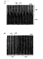
- Figs. 3A and 3B and Fig. 4 show SEM photographs of mark pieces formed in the embodiment. The magnification is as indicated in the figures, the dye is removed, and the deformed portion of a polycarbonate substrate and its periphery are photographed.
- Fig. 3A shows the vicinity of a deformed part in the direction orthogonal to the groove and land, and while the groove 14A and the land 14B are clear in a non-deformed portion 14P, those are deformed and boundaries are unclear in a deformed portion 14Q.
- Fig. 3A shows the vicinity of a deformed part in the direction orthogonal to the groove and land, and while the groove 14A and the land 14B are clear in a non-deformed portion 14P, those are deformed and boundaries are unclear in a deformed portion 14Q.
- FIG. 3B shows under magnification the vicinity of an end of a deformed part in the direction parallel to the groove and land, and similarly, while the groove 14A and the land 14B are clear in a non-deformed portion 14P, those are deformed and boundaries are unclear in a deformed portion 14Q.
- Fig. 4 shows a state of the periphery of the end of the mark piece MA, and a similar result is obtained.
- the invention is not limited to the foregoing embodiment, but can be variously modified within the scope not departing from the gist of the invention.
- the following are also included.
- the readout signal is excellently modulated, and information can be read out without fail.
- the invention is suitable for copyright protection or the like in a recordable optical disc such as a DVD-R, Blu-ray Disc, DVD+R, CD-R or next generation disk of HD-DVD or the like, or in a rewritable optical disc.
Claims (6)
- Optisches Informationsaufzeichnungsmedium (10), das Folgendes umfasst:ein Substrat mit Lands (14B) und Rillen (14A);eine auf dem Substrat angeordnete Aufzeichnungsschicht;einen Hauptinformationsaufzeichnungsbereich (16) undeinen Unterinformationsaufzeichnungsbereich (14);wobei der Unterinformationsaufzeichnungsbereich (14) Unterinformationen auf der Basis einer Substratverformung enthält; dadurch gekennzeichnet, dass:die Substratverformung eine Verformung über mehrere Rillen (14A) und Lands (14B) enthält.
- Optisches Informationsaufzeichnungsmedium (10) nach Anspruch 1, wobei die Unterinformationen zu einer Strichcodeform ausgebildet sind.
- Optisches Informationsaufzeichnungsmedium (10) nach Anspruch 1, wobei die Aufzeichnungsschicht einen organischen Farbstoff enthält.
- Verfahren zum Herstellen eines optischen Informationsaufzeichnungsmediums (10), wobei das Medium ein Substrat mit Lands (14B) und Rillen (14A), eine darauf ausgebildete Aufzeichnungsschicht, einen Hauptinformationsaufzeichnungsbereich (16) und einen Unterinformationsaufzeichnungsbereich (14) enthält, umfassend die folgenden Schritte:Sequenzielles Bewegen eines Laserstrahls (30) in einer radialen Richtung des optischen Informationsaufzeichnungsmediums (10) zum Aufzeichnen von Unterinformationen in dem Unterinformationsaufzeichnungsbereich (14) durch:Ausbilden von Markierungsstücken (MA, MB), so dass benachbarte Enden von benachbarten Markierungsstücken (MA, MB), wobei jedes Markierungsstück durch einen Aufzeichnungsprozess ausgebildet wird, einander überlappen; undAusbilden von Strichcodeinformationen mit einer spezifizierten Länge;wobei das Aufzeichnen der Unterinformationen den Schritt des Verformens des Substrats umfasst, dadurch gekennzeichnet, dass:der Schritt des Verformens des Substrats das Verformen über mehrere Rillen und Lands beinhaltet.
- Verfahren zum Herstellen des optischen Informationsaufzeichnungsmediums (10) nach Anspruch 4, wobei der Schritt des sequenziellen Bewegens eines Laserstrahls (30) das sequenzielle Bewegen eines Laserstrahls (30) mit einer elliptischen Gestalt umfasst, die dünner ist als eine durch die Lands (14B) und die Rillen (14A) definierte Teilung.
- Verfahren zum Herstellen des optischen Informationsaufzeichnungsmediums (10) nach Anspruch 4, wobei der Schritt des Aufzeichnens von Unterinformationen in dem Unterinformationsaufzeichnungsbereich (14) das Aufzeichnen der Unterinformationen mit einer Energiedichte pro Flächeneinheit im Wesentlichen gleich der des Hauptinformationsaufzeichnens des Hauptinformationsaufzeichnungsbereichs (16) umfasst.
Applications Claiming Priority (1)
| Application Number | Priority Date | Filing Date | Title |
|---|---|---|---|
| JP2004291763A JP2006107600A (ja) | 2004-10-04 | 2004-10-04 | 光情報記録媒体及びその製造方法 |
Publications (3)
| Publication Number | Publication Date |
|---|---|
| EP1643495A2 EP1643495A2 (de) | 2006-04-05 |
| EP1643495A3 EP1643495A3 (de) | 2006-11-22 |
| EP1643495B1 true EP1643495B1 (de) | 2012-04-18 |
Family
ID=35550642
Family Applications (1)
| Application Number | Title | Priority Date | Filing Date |
|---|---|---|---|
| EP05256178A Active EP1643495B1 (de) | 2004-10-04 | 2005-10-03 | Optisches Informationsaufzeichnungsmedium und Verfahren zur Herstellung desselben |
Country Status (7)
| Country | Link |
|---|---|
| US (1) | US7903535B2 (de) |
| EP (1) | EP1643495B1 (de) |
| JP (1) | JP2006107600A (de) |
| KR (1) | KR100759829B1 (de) |
| CN (2) | CN101299340B (de) |
| HK (1) | HK1089865A1 (de) |
| TW (1) | TW200627416A (de) |
Families Citing this family (5)
| Publication number | Priority date | Publication date | Assignee | Title |
|---|---|---|---|---|
| JP2006155785A (ja) * | 2004-11-30 | 2006-06-15 | Toshiba Corp | 情報記憶媒体、スタンパー、ディスク装置、管理情報再生方法 |
| JP2007323773A (ja) * | 2006-06-02 | 2007-12-13 | Toshiba Corp | 光ディスク、情報記録方法、情報再生方法、およびディスクドライブ |
| EP2594171B1 (de) * | 2011-11-16 | 2014-04-16 | Nestec S.A. | Halter und Kapsel zur Herstellung eines Getränks durch Zentrifugieren, System und Verfahren zur Herstellung eines Getränks durch Zentrifugieren |
| ES2611463T3 (es) * | 2013-09-30 | 2017-05-09 | Nestec S.A. | Soporte de código y cápsula para preparar una bebida por centrifugación, sistema y método para preparar una bebida por centrifugación |
| CN114189744B (zh) * | 2021-11-03 | 2024-02-23 | 日立楼宇技术(广州)有限公司 | 基于二维码的多媒体播放方法、系统、装置及显示屏 |
Family Cites Families (21)
| Publication number | Priority date | Publication date | Assignee | Title |
|---|---|---|---|---|
| JPH0512710A (ja) | 1991-07-03 | 1993-01-22 | Hitachi Maxell Ltd | 光情報記録媒体 |
| JPH0636287A (ja) | 1992-07-20 | 1994-02-10 | Ricoh Co Ltd | 光ディスク原盤及び原盤露光装置 |
| KR100481596B1 (ko) * | 1995-10-09 | 2005-04-11 | 마쯔시다덴기산교 가부시키가이샤 | 컨텐츠 재생 장치 및 컨텐츠 재생 방법 |
| JP3225035B2 (ja) | 1995-10-09 | 2001-11-05 | 松下電器産業株式会社 | 光ディスク、及び光ディスク再生装置 |
| JP3209126B2 (ja) | 1996-12-20 | 2001-09-17 | 日本ビクター株式会社 | 光記録媒体及び光ディスク再生装置並びに光ディスク再生方法 |
| US5946286A (en) * | 1997-03-20 | 1999-08-31 | Imation Corp. | Customized graphics for dual layer optical discs |
| US5890818A (en) * | 1997-06-30 | 1999-04-06 | Pitney Bowes Inc. | Pixel splitting to improve bar code readability |
| JPH1186423A (ja) | 1997-08-30 | 1999-03-30 | Victor Co Of Japan Ltd | ディスク,その識別方法・装置,その再生装置 |
| JP3743178B2 (ja) * | 1998-10-05 | 2006-02-08 | ヤマハ株式会社 | 記録可能型光ディスクおよび光ディスク記録装置 |
| AU6125299A (en) * | 1998-10-21 | 2000-05-08 | Matsushita Electric Industrial Co., Ltd. | Optical information recording medium, and method and apparatus for recording andreproduction |
| JP2001101791A (ja) | 1999-09-28 | 2001-04-13 | Ricoh Co Ltd | 光情報記録媒体及び光情報記録再生装置 |
| JP2001325746A (ja) | 2000-05-15 | 2001-11-22 | Victor Co Of Japan Ltd | 光情報記録媒体 |
| JPWO2002037483A1 (ja) | 2000-11-06 | 2004-03-11 | 松下電器産業株式会社 | 光記録媒体、光記録媒体製造方法、光記録媒体製造装置、プログラム、および媒体 |
| JP2002197724A (ja) * | 2000-12-26 | 2002-07-12 | Pioneer Electronic Corp | 光記録媒体 |
| JP2003030856A (ja) * | 2001-07-17 | 2003-01-31 | Pioneer Electronic Corp | 光ディスク並びに記録及び再生装置 |
| TWI229557B (en) * | 2001-10-23 | 2005-03-11 | Samsung Electronics Co Ltd | Method and apparatus for reproducing contents from information storage medium in interactive mode |
| DE60334584D1 (de) | 2002-02-18 | 2010-11-25 | Koninkl Philips Electronics Nv | Optisches Aufzeichnungsmedium und dessen Wiedergabeverfahren |
| US7684295B2 (en) * | 2003-07-08 | 2010-03-23 | Lg Electronics, Inc. | Recording medium, method of recording control information on a recording medium, method of recording/reproducing data using control information, and apparatus for recording/reproducing data using control information |
| JP2006048772A (ja) * | 2004-07-30 | 2006-02-16 | Taiyo Yuden Co Ltd | 光情報記録媒体 |
| JP2006079773A (ja) | 2004-09-13 | 2006-03-23 | Hitachi Maxell Ltd | 光ディスク及びその記録方法 |
| JP2006085791A (ja) | 2004-09-15 | 2006-03-30 | Hitachi Maxell Ltd | 光情報記録媒体 |
-
2004
- 2004-10-04 JP JP2004291763A patent/JP2006107600A/ja not_active Withdrawn
-
2005
- 2005-09-30 TW TW094134410A patent/TW200627416A/zh unknown
- 2005-09-30 KR KR1020050091834A patent/KR100759829B1/ko active IP Right Grant
- 2005-10-03 EP EP05256178A patent/EP1643495B1/de active Active
- 2005-10-04 US US11/243,130 patent/US7903535B2/en not_active Expired - Fee Related
- 2005-10-08 CN CN200810083950XA patent/CN101299340B/zh active Active
- 2005-10-08 CN CN2005101082743A patent/CN1770300B/zh active Active
-
2006
- 2006-10-26 HK HK06111810.9A patent/HK1089865A1/xx not_active IP Right Cessation
Also Published As
| Publication number | Publication date |
|---|---|
| US7903535B2 (en) | 2011-03-08 |
| EP1643495A2 (de) | 2006-04-05 |
| CN1770300A (zh) | 2006-05-10 |
| KR20060051896A (ko) | 2006-05-19 |
| EP1643495A3 (de) | 2006-11-22 |
| JP2006107600A (ja) | 2006-04-20 |
| CN101299340A (zh) | 2008-11-05 |
| CN101299340B (zh) | 2011-04-20 |
| HK1089865A1 (en) | 2006-12-08 |
| CN1770300B (zh) | 2011-01-12 |
| TW200627416A (en) | 2006-08-01 |
| KR100759829B1 (ko) | 2007-09-18 |
| US20060083155A1 (en) | 2006-04-20 |
Similar Documents
| Publication | Publication Date | Title |
|---|---|---|
| US7239601B2 (en) | Optical recording medium, method of manufacturing optical recording medium, apparatus for manufacturing optical recording medium, program, and medium | |
| EP1643495B1 (de) | Optisches Informationsaufzeichnungsmedium und Verfahren zur Herstellung desselben | |
| US7972673B2 (en) | Optical recording medium | |
| US20030193882A1 (en) | Optical information recording medium and method for producing the same | |
| US7038998B2 (en) | Optical recording disk having land and groove wobbled at outer circumference side | |
| US20080137504A1 (en) | Method Of Writing Data On A Master Substrate For Optical Recording | |
| JP2001273682A (ja) | 記録型ディスク及びその製造方法 | |
| Abe et al. | Master recording for high-density disk using 248 nm laser beam recorder | |
| EP1622133A2 (de) | Optisches Informationsaufzeichnungsmedium | |
| KR20050085027A (ko) | 디스크 기판 및 광디스크 | |
| JP5112696B2 (ja) | マルチスタック光記憶媒体 | |
| US20090129220A1 (en) | Information recording medium, information reproducing apparatus and method, and apparatus for and method of manufacturing the information recording | |
| JP2751868B2 (ja) | 光記録媒体およびその記録再生方法 | |
| JP2003022576A (ja) | 光情報記録媒体及び原盤の製造方法 | |
| JP4277812B2 (ja) | 光ディスク記録媒体、ディスク製造方法 | |
| Kondo et al. | 1-beam-mastering of groove recording disc with LPP address | |
| JP2007280518A (ja) | 光ディスク | |
| JPH0917032A (ja) | 光情報記録媒体 | |
| JP2001291281A (ja) | 記録型ディスク及びその製造方法 | |
| JP2007317341A (ja) | 光情報記録媒体およびその記録方法 | |
| JPS62128038A (ja) | 光デイスク基板 | |
| JPH03120636A (ja) | 情報記録媒体およびその製造方法 | |
| JP2001126320A (ja) | 光ディスク媒体の情報記録方法および光ディスク原盤の製造方法 | |
| JPS6379235A (ja) | 光デイスク | |
| JP2009116984A (ja) | 薄型光記録媒体及び記録再生装置 |
Legal Events
| Date | Code | Title | Description |
|---|---|---|---|
| PUAI | Public reference made under article 153(3) epc to a published international application that has entered the european phase |
Free format text: ORIGINAL CODE: 0009012 |
|
| AK | Designated contracting states |
Kind code of ref document: A2 Designated state(s): AT BE BG CH CY CZ DE DK EE ES FI FR GB GR HU IE IS IT LI LT LU LV MC NL PL PT RO SE SI SK TR |
|
| AX | Request for extension of the european patent |
Extension state: AL BA HR MK YU |
|
| 17P | Request for examination filed |
Effective date: 20060421 |
|
| PUAL | Search report despatched |
Free format text: ORIGINAL CODE: 0009013 |
|
| AK | Designated contracting states |
Kind code of ref document: A3 Designated state(s): AT BE BG CH CY CZ DE DK EE ES FI FR GB GR HU IE IS IT LI LT LU LV MC NL PL PT RO SE SI SK TR |
|
| AX | Request for extension of the european patent |
Extension state: AL BA HR MK YU |
|
| AKX | Designation fees paid |
Designated state(s): AT BE BG CH CY LI |
|
| 17Q | First examination report despatched |
Effective date: 20070702 |
|
| REG | Reference to a national code |
Ref country code: DE Ref legal event code: 8566 |
|
| GRAP | Despatch of communication of intention to grant a patent |
Free format text: ORIGINAL CODE: EPIDOSNIGR1 |
|
| RBV | Designated contracting states (corrected) |
Designated state(s): DE FR GB IT NL |
|
| GRAS | Grant fee paid |
Free format text: ORIGINAL CODE: EPIDOSNIGR3 |
|
| GRAA | (expected) grant |
Free format text: ORIGINAL CODE: 0009210 |
|
| AK | Designated contracting states |
Kind code of ref document: B1 Designated state(s): DE FR GB IT NL |
|
| REG | Reference to a national code |
Ref country code: GB Ref legal event code: FG4D |
|
| REG | Reference to a national code |
Ref country code: DE Ref legal event code: R096 Ref document number: 602005033724 Country of ref document: DE Effective date: 20120614 |
|
| REG | Reference to a national code |
Ref country code: NL Ref legal event code: T3 |
|
| PLBE | No opposition filed within time limit |
Free format text: ORIGINAL CODE: 0009261 |
|
| STAA | Information on the status of an ep patent application or granted ep patent |
Free format text: STATUS: NO OPPOSITION FILED WITHIN TIME LIMIT |
|
| 26N | No opposition filed |
Effective date: 20130121 |
|
| REG | Reference to a national code |
Ref country code: DE Ref legal event code: R097 Ref document number: 602005033724 Country of ref document: DE Effective date: 20130121 |
|
| REG | Reference to a national code |
Ref country code: FR Ref legal event code: PLFP Year of fee payment: 12 |
|
| REG | Reference to a national code |
Ref country code: FR Ref legal event code: PLFP Year of fee payment: 13 |
|
| REG | Reference to a national code |
Ref country code: FR Ref legal event code: PLFP Year of fee payment: 14 |
|
| P01 | Opt-out of the competence of the unified patent court (upc) registered |
Effective date: 20230509 |
|
| PGFP | Annual fee paid to national office [announced via postgrant information from national office to epo] |
Ref country code: NL Payment date: 20230915 Year of fee payment: 19 Ref country code: IT Payment date: 20230913 Year of fee payment: 19 Ref country code: GB Payment date: 20230831 Year of fee payment: 19 |
|
| PGFP | Annual fee paid to national office [announced via postgrant information from national office to epo] |
Ref country code: FR Payment date: 20230911 Year of fee payment: 19 |
|
| PGFP | Annual fee paid to national office [announced via postgrant information from national office to epo] |
Ref country code: DE Payment date: 20230830 Year of fee payment: 19 |