EP1636466B1 - Brennkraftmaschine - Google Patents
Brennkraftmaschine Download PDFInfo
- Publication number
- EP1636466B1 EP1636466B1 EP04737352A EP04737352A EP1636466B1 EP 1636466 B1 EP1636466 B1 EP 1636466B1 EP 04737352 A EP04737352 A EP 04737352A EP 04737352 A EP04737352 A EP 04737352A EP 1636466 B1 EP1636466 B1 EP 1636466B1
- Authority
- EP
- European Patent Office
- Prior art keywords
- cam
- internal combustion
- combustion engine
- camshaft
- particular according
- Prior art date
- Legal status (The legal status is an assumption and is not a legal conclusion. Google has not performed a legal analysis and makes no representation as to the accuracy of the status listed.)
- Expired - Lifetime
Links
- 238000002485 combustion reaction Methods 0.000 title claims description 20
- 230000007704 transition Effects 0.000 claims description 4
- 230000013011 mating Effects 0.000 claims description 3
- 238000000034 method Methods 0.000 description 9
- 238000007906 compression Methods 0.000 description 7
- 230000006835 compression Effects 0.000 description 7
- 238000006073 displacement reaction Methods 0.000 description 5
- 230000008569 process Effects 0.000 description 4
- 230000008901 benefit Effects 0.000 description 2
- 230000001419 dependent effect Effects 0.000 description 2
- 230000004048 modification Effects 0.000 description 2
- 238000012986 modification Methods 0.000 description 2
- 230000008859 change Effects 0.000 description 1
- 238000013461 design Methods 0.000 description 1
- 238000011161 development Methods 0.000 description 1
- 238000009472 formulation Methods 0.000 description 1
- 230000003993 interaction Effects 0.000 description 1
- 230000001050 lubricating effect Effects 0.000 description 1
- 238000004519 manufacturing process Methods 0.000 description 1
- 239000000463 material Substances 0.000 description 1
- 238000005259 measurement Methods 0.000 description 1
- 239000000203 mixture Substances 0.000 description 1
- 238000007493 shaping process Methods 0.000 description 1
- 238000012360 testing method Methods 0.000 description 1
Images


Classifications
-
- F—MECHANICAL ENGINEERING; LIGHTING; HEATING; WEAPONS; BLASTING
- F01—MACHINES OR ENGINES IN GENERAL; ENGINE PLANTS IN GENERAL; STEAM ENGINES
- F01L—CYCLICALLY OPERATING VALVES FOR MACHINES OR ENGINES
- F01L13/00—Modifications of valve-gear to facilitate reversing, braking, starting, changing compression ratio, or other specific operations
- F01L13/0015—Modifications of valve-gear to facilitate reversing, braking, starting, changing compression ratio, or other specific operations for optimising engine performances by modifying valve lift according to various working parameters, e.g. rotational speed, load, torque
-
- F—MECHANICAL ENGINEERING; LIGHTING; HEATING; WEAPONS; BLASTING
- F01—MACHINES OR ENGINES IN GENERAL; ENGINE PLANTS IN GENERAL; STEAM ENGINES
- F01L—CYCLICALLY OPERATING VALVES FOR MACHINES OR ENGINES
- F01L1/00—Valve-gear or valve arrangements, e.g. lift-valve gear
- F01L1/02—Valve drive
- F01L1/04—Valve drive by means of cams, camshafts, cam discs, eccentrics or the like
- F01L1/047—Camshafts
-
- F—MECHANICAL ENGINEERING; LIGHTING; HEATING; WEAPONS; BLASTING
- F01—MACHINES OR ENGINES IN GENERAL; ENGINE PLANTS IN GENERAL; STEAM ENGINES
- F01L—CYCLICALLY OPERATING VALVES FOR MACHINES OR ENGINES
- F01L1/00—Valve-gear or valve arrangements, e.g. lift-valve gear
- F01L1/02—Valve drive
- F01L1/04—Valve drive by means of cams, camshafts, cam discs, eccentrics or the like
- F01L1/08—Shape of cams
-
- F—MECHANICAL ENGINEERING; LIGHTING; HEATING; WEAPONS; BLASTING
- F01—MACHINES OR ENGINES IN GENERAL; ENGINE PLANTS IN GENERAL; STEAM ENGINES
- F01L—CYCLICALLY OPERATING VALVES FOR MACHINES OR ENGINES
- F01L1/00—Valve-gear or valve arrangements, e.g. lift-valve gear
- F01L1/34—Valve-gear or valve arrangements, e.g. lift-valve gear characterised by the provision of means for changing the timing of the valves without changing the duration of opening and without affecting the magnitude of the valve lift
-
- F—MECHANICAL ENGINEERING; LIGHTING; HEATING; WEAPONS; BLASTING
- F01—MACHINES OR ENGINES IN GENERAL; ENGINE PLANTS IN GENERAL; STEAM ENGINES
- F01L—CYCLICALLY OPERATING VALVES FOR MACHINES OR ENGINES
- F01L13/00—Modifications of valve-gear to facilitate reversing, braking, starting, changing compression ratio, or other specific operations
- F01L13/0015—Modifications of valve-gear to facilitate reversing, braking, starting, changing compression ratio, or other specific operations for optimising engine performances by modifying valve lift according to various working parameters, e.g. rotational speed, load, torque
- F01L13/0057—Modifications of valve-gear to facilitate reversing, braking, starting, changing compression ratio, or other specific operations for optimising engine performances by modifying valve lift according to various working parameters, e.g. rotational speed, load, torque by splittable or deformable cams
-
- F—MECHANICAL ENGINEERING; LIGHTING; HEATING; WEAPONS; BLASTING
- F01—MACHINES OR ENGINES IN GENERAL; ENGINE PLANTS IN GENERAL; STEAM ENGINES
- F01L—CYCLICALLY OPERATING VALVES FOR MACHINES OR ENGINES
- F01L2305/00—Valve arrangements comprising rollers
-
- Y—GENERAL TAGGING OF NEW TECHNOLOGICAL DEVELOPMENTS; GENERAL TAGGING OF CROSS-SECTIONAL TECHNOLOGIES SPANNING OVER SEVERAL SECTIONS OF THE IPC; TECHNICAL SUBJECTS COVERED BY FORMER USPC CROSS-REFERENCE ART COLLECTIONS [XRACs] AND DIGESTS
- Y10—TECHNICAL SUBJECTS COVERED BY FORMER USPC
- Y10T—TECHNICAL SUBJECTS COVERED BY FORMER US CLASSIFICATION
- Y10T29/00—Metal working
- Y10T29/49—Method of mechanical manufacture
- Y10T29/49229—Prime mover or fluid pump making
- Y10T29/49293—Camshaft making
Definitions
- the invention relates to an internal combustion engine having a variable valve drive device with at least one camshaft having at least one cam arrangement, which has a substantially radially with respect to the camshaft slidable cam and at least one, preferably two camshaft fixed base disks
- a system for driving and controlling a cam for an internal combustion engine is known.
- the cam is movable in the radial direction of the camshaft and includes a lift portion that moves fore and aft in the direction of the valve to be actuated, and includes means for engaging the cam with the camshaft and disengaging the cam from the camshaft in accordance with engine operating conditions.
- the displacement of the cam takes place hydraulically.
- a cam-type valve actuator for a lift valve which includes a cam having a rigid component radially adjustable between a retracted and an extended position, which is guided on the associated camshaft and associated with stops for limiting its exit movement.
- the displacement of the cam is effected by a pressure medium supplied in a longitudinal bore of the camshaft.
- variable valve trains have the disadvantage that complex control systems are required, and that for active actuation of the cam, the hydraulic actuation means must be provided at a relatively high pressure.
- variable valve trains are usually suitable only for a certain type of operation, ie either for hydraulic, mechanical or electrical actuation.
- the publication describes DE 102 17 695 A1 a starting method with changed timing of the intake valves to reduce the compression work during starting. Also the JP 1-1117840 A discloses the change in intake timing during the startup phase.
- the object of the invention is to avoid these disadvantages and to propose a simple variable valve train device, which is suitable for external actuation with different actuating means, in particular to facilitate the starting process of an internal combustion engine.
- the cam is actuated by an adjusting member arranged laterally of the camshaft.
- the radially displaceable cam is thus controlled directly by the adjusting member arranged outside the camshaft.
- the radially displaceable cam can be controlled in each case before or during the lifting phase of the adjusting member in the stroke position.
- the adjusting member is formed by an actuating roller, which can be adjusted for example via an eccentric.
- the radially displaceable cam can be supported on the camshaft via a resilient element and is pushed back after the lifting phase of this elastic element back into its initial position behind the base circle.
- the cam is mounted on sliding surfaces on circular driving surfaces of the camshaft. Radius and angular position of the sliding surfaces are arranged so that no self-locking occurs at the beginning of the displacement of the cam.
- the cam is designed in two parts, wherein viewed from a side view of the actuator, viewed in a side view substantially fork-shaped and encloses a cam lobe having second part, wherein the first and second part preferably via pins connected to each other.
- the acted upon by the adjusting member first part encloses the cam elevation surface having a second part U-shaped and is connected thereto by two pins after being pushed onto the camshaft so that the first and second part of the cam form a cam unit.
- the adjusting member has at least one engagement surface which cooperates with a corresponding corresponding counter surface of the first part of the cam.
- the adjusting member has a substantially U-shaped cross-section with two legs forming the engagement surfaces, which are arranged at a distance from one another, which is greater than the width of the second part of the cam is very advantageous.
- the adjusting member is effective only on the first part of the slidable cam and formed with a U-shaped cross section, in which the cam lobe of the second part can dip, so that no valve lift can take place in the working stroke phase of the internal combustion engine.
- At least one base disc has a radial recess for mounting a pin, wherein preferably recesses of one base disc are offset from the recesses of the other base disc.
- At least one base disc has a Rampenerhöhung, which forms a total cam together with the cam lobe of the second part of the cam.
- the Rampenerhöhung the base circular discs form together with the cam lobe of the sliding cam from the total cam. Due to the Rampenerhöhungen the base circular disks and a defined base opening of the gas exchange valve can be generated.
- the counter surface of the first part has a different shape from a cylindrical surface and defines a control surface, so that the Ventilhubkurve of the actuated lift valve from the shape of the mating surface of the first part and the shape of the cam lobe of the second Part of the cam composed, wherein preferably the counter surface and the cam lobe of the cam are formed so that the valve lift curve, in particular in the region of the transition between the base circle of the base discs for cam lobing steadily.
- the fully variable valve actuation can be used in particular to facilitate the starting process in a diesel internal combustion engine.
- the intake valve opening time is retarded and / or the intake closing time is advanced. This allows sufficient ignition conditions be achieved with lowered compression ratios.
- the compression end temperature can be substantially increased if a repeated compression takes place with retractions of the cylinder contents in the intake manifold.
- the shift of the opening time or the closing time can be up to 120 ° crank angle or more. Measurements have shown that a significant increase in the charge temperature in the region of top dead center of the compression of, for example, 70 ° to 120 °, depending on the speed can be achieved.
- valve drive device 2 has two integral with the camshaft 1 base circular disks 3, a substantially radially displaceable on the camshaft 1 cam 4 and a directly acting on the cam 4 adjusting 5.
- the cam 4 consists of two nested parts, one acted upon by the adjusting member 5 first part 6 and a cam lobe 7 having second part 8.
- First and second part 6, 8 engage driving surfaces 9 of the camshaft 1, wherein the cam 4 in the area the driving surfaces have 9 sliding surfaces 10.
- the first part 6 has a fork-shaped cross section, which comprises the second part 8, as seen from Fig. 2 is recognizable.
- Diametrically with respect to the cam elevation 7, the first part 6 has a control cam 11, on which the adjusting member 5 acts on the cam 4.
- the adjusting member 5 has in the embodiment, an actuating roller 12 with a in Substantially U-shaped cross section with two legs 23, which are formed by edges 13 of the actuating roller 12.
- edges 13 act on engagement surfaces 21 on by the control surfaces 11 of the first part 6 of the cam 4 formed counter-surfaces 22 a.
- the distance a of the edges 13 corresponds at least to the width b of the second part 8, so that no valve lift can take place in the working phase of the internal combustion engine.
- the cam 4 is biased by an elastic member 14, wherein the elastic member 14, the cam 4 in the in Fig. 5 and Fig. 6 shown rest position presses, in which only the base circular disks 3 act on the valve actuator 15.
- the first part 6 and the second part 8 of the cam 4 are based on each other and are connected to each other with pins 16. Via the elastic element 14, the cam 4 is pressed to a zero-stroke position, if there is no frictional connection via the feed roller 12.
- radial mounting grooves 17 are provided in the base disks. The mounting grooves 17 are alternately arranged in the base disks 3 so as not to interrupt the contact of the valve actuator 15 to the base disks 3.
- the actuating roller 12 is thus designed so that the cam lobe 7 dips into the free space 18 between the edges 13 when the internal combustion engine is in the working cycle. Outside the Zusüu fürsphase and the valve lift is no contact between the actuating roller 12 and the cam 4 is present, so that the valve actuator 15, which may be formed by a plunger, finger lever or rocker arm, in contact with the arranged on the camshaft 4 outside of the actuating roller 12 fixed base disks 3 is.
- the driving surfaces 9, as well as the sliding surfaces 10, are arcuate. Your angular position and its radius is chosen so that the lowest possible adjustment possible, and that in any case, self-locking, especially at the beginning of the displacement of the cam 4, is avoided. Via a central bore 18 in the camshaft 1, pressure oil for lubricating the sliding surfaces 10 can be supplied without problems.
- the base circular disks 3 may have a ramp region 19 which, together with the cam lobe 7 of the displaceable cam 4, forms the total cam.
- the ramp region 19 defines a minimum stroke of the gas exchange valve, not shown, and allows a smooth transition from the base circle 20 of the base plate 3 on the cam elevation 7 and vice versa.
- the shape of the valve lift curve is due to the interaction the control cam 11 defined with the cam lobe 7 of the displaceable cam 4 during the lifting phase. By appropriate shaping of the control cam 11 and the cam elevation 7, a uniform transition from the base circle 20 to the cam elevation 7 and vice versa is made possible.
- Fig. 1 shows the valve drive device 2 to Verstellbeginn.
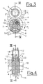
- the actuating roller 12 is moved from the rest position indicated by reference numeral 12 'and indicated by dashed lines in the direction of the camshaft 1 according to the arrow P 1 , so that the edges 13 of the actuating roller 12 act on the control cam 11 of the first part 6 of the cam 4 and the cam 4 from the rest position against the force of the elastic element 14 in the FIG. 3 and FIG. 4 deflected illustrated stroke position.
- the cam elevation 7 projects beyond the base circular disks 3 and thus acts on the valve actuator 15.
- the camshaft 1 runs in the direction indicated by the arrow P 2 rotation.
- the assembly of the first part 6 and the second part 8 on the camshaft 1 is carried out by pushing the same on the driving surfaces 9 from different sides. If the cam 4 against the force of the elastic element 14 in the in Fig. 3 Pressed stroke position shown, the pins 16 can be used by the radial grooves in the direction of the axis 1 a of the camshaft 1.
- variable valve train 2 The advantage of the variable valve train 2 is that a large number of possible variations is possible by the external actuation by means of the adjusting member 5.
- the adjusting member 5 can be operated pneumatically, hydraulically, electrically, electromagnetically, mechanically or in combination thereof.
Landscapes
- Engineering & Computer Science (AREA)
- Mechanical Engineering (AREA)
- General Engineering & Computer Science (AREA)
- Valve Device For Special Equipments (AREA)
Description
- Die Erfindung betrifft eine Brennkraftmaschine mit einer variablen Ventiltriebsvorrichtung mit zumindest einer Nockenwelle mit mindestens einer Nockenanordnung, welche einen im Wesentlichen radial bezüglich der Nockenwelle verschiebbaren Nocken und zumindest eine, vorzugsweise zwei nockenwellenfeste Grundkreisscheiben aufweist
- Aus der
DE 100 53 776 A1 ist ein System zum Antreiben und Steuern eines Nockens für einen Verbrennungsmotor bekannt. Der Nocken ist in der Radialrichtung der Nockenwelle bewegbar und umfasst einen Hubabschnitt, welcher sich vorwärts und rückwärts in der Richtung des zu betätigenden Ventils bewegt, wobei eine Vorrichtung vorgesehen ist, welche den Nocken mit der Nockenwelle in Eingriff bringt und den Nocken von der Nockenwelle löst, wobei dies in Übereinstimmung mit Motorbetriebszuständen erfolgt. Die Verschiebung des Nockens erfolgt dabei hydraulisch. - Aus der
DE 42 22 477 A1 ist eine nockenbestückte Ventilbetätigung für ein Hubventil bekannt, welche einen Nocken mit einem in radialer Richtung zwischen einer eingefahrenen und einer ausgefahrenen Position verstellbaren starren Bauteil enthält, welcher an der zugehörigen Nockenwelle geführt ist und dem Anschläge zur Begrenzung seiner Ausfahrtbewegung zugeordnet sind. Die Verschiebung des Nockens erfolgt durch ein in einer Längsbohrung der Nockenwelle zugeführtes Druckmittel. - Hydraulisch betätigte variable Ventiltriebe haben den Nachteil, dass komplexe Regelungssysteme erforderlich sind, und dass zur aktiven Betätigung des Nockens das hydraulische Betätigungsmittel bei relativ hohem Druck bereitgestellt werden muss. Darüber hinaus eignen variable Ventiltriebe meistens nur für eine bestimmte Art von Betätigung, also entweder für hydraulische, mechanische oder für elektrische Betätigung.
- Aus den Veröffentlichungen
DE 41 41 482 A1 ,DE 37 37 824 A1 undDE 199 08 435 A1 ist es bekannt, beim Startvorgang Impulsaufladung durchzuführen bzw. den Einlassbeginn in der Startphase zu verzögern, um den Startvorgang zu vereinfachen. - Weiters beschreibt die Veröffentlichung
DE 102 17 695 A1 ein Startverfahren mit veränderten Steuerzeiten der Einlassventile zur Verringerung der Kompressionsarbeit während des Startens. Auch dieJP 1-1117840 A - Aufgabe der Erfindung ist es, diese Nachteile zu vermeiden und eine einfache variable Ventiltriebseinrichtung vorzuschlagen, welche für externe Betätigung mit verschiedenen Betätigungsmitteln geeignet ist, insbesondere um den Startvorgang einer Brennkraftmaschine zu erleichtern.
- Erfindungsgemäß wird dies dadurch erreicht, dass der Nocken durch ein seitlich der Nockenwelle angeordnetes Verstellglied ansteuerbar ist. Der radial verschiebbare Nocken wird somit direkt vom außerhalb der Nockenwelle angeordneten Verstellglied angesteuert. Dies hat den Vorteil, dass neben hydraulischen oder pneumatischen Verstellgliedern auch rein mechanische oder elektrische bzw. elektromagnetische Verstellglieder eingesetzt werden können. Die variable Ventiltriebsvorrichtung ist somit nicht auf eine bestimmte Art von Verstellgliedern eingeschränkt.
- Der radial verschiebbare Nocken kann jeweils vor oder auch während der Hubphase vom Verstellglied in die Hubposition gesteuert werden. Vorzugsweise ist das Verstellglied durch eine Betätigungsrolle gebildet, welche beispielsweise über einen Exzenter verstellt werden kann.
- Der radial verschiebbare Nocken kann sich über ein federndes Element an der Nockenwelle abstützen und wird nach der Hubphase von diesem elastischen Element wieder in seine Ausgangslage hinter den Grundkreis zurückgeschoben.
- Um eine klemmfreie Verschiebung es Nockens zu ermöglichen, ist es vorteilhaft, wenn der Nocken über Gleitflächen auf kreisförmigen Mitnahmeflächen der Nockenwelle gelagert ist. Radius und Winkellage der Gleitflächen sind so angeordnet, dass beim Beginn der Verschiebung des Nockens keine Selbsthemmung auftritt.
- In einer bevorzugten Ausführungsvariante der Erfindung ist vorgesehen, dass der Nocken zweiteilig ausgeführt ist, wobei ein vom Verstellglied beaufschlagter erster Teil in einer Seitenansicht betrachtet, im Wesentlichen gabelförmig ausgebildet ist und einen eine Nockenerhebung aufweisenden zweiten Teil umschließt, wobei erster und zweiter Teil vorzugsweise über Stifte miteinander verbunden sind. Der vom Verstellglied beaufschlagte erste Teil umschließt den eine Nockenerhebungsfläche aufweisenden zweiten Teil U-förmig und wird mit diesem durch zwei Stifte nach dem Aufschieben auf die Nockenwelle verbunden, so dass erster und zweiter Teil des Nockens eine Nockeneinheit bilden.
- Das Verstellglied weist zumindest eine Angriffsfläche auf, welche mit einer entsprechenden korrespondierenden Gegenfläche des ersten Teiles des Nockens zusammenwirkt.
- Sehr vorteilhaft ist es, wenn das Verstellglied einen im Wesentlichen U-förmigen Querschnitt mit zwei die Angriffsflächen ausbildenden Schenkeln aufweist, welche in einem Abstand voneinander angeordnet sind, welcher größer ist, als die Breite des zweiten Teiles des Nockens. Das Verstellglied ist nur auf den ersten Teil des verschiebbaren Nockens wirksam und mit einem U-förmigen Querschnitt ausgebildet, in welchen die Nockenerhebung des zweiten Teiles eintauchen kann, so dass in der Arbeitstaktphase der Verbrennungskraftmaschine kein Ventilhub stattfinden kann.
- Um eine einfache Montage der Einzelteile des Nockens auf der Nockenwelle zu ermöglichen, ist es besonders vorteilhaft, wenn zumindest eine Grundkreisscheibe eine radiale Ausnehmung zur Montage eines Stiftes aufweist, wobei vorzugsweise Ausnehmungen der einen Grundkreisscheibe versetzt zu den Ausnehmungen der anderen Grundkreisscheibe angeordnet sind. Dadurch, dass die radialen Nuten in den beiden Grundkreisscheiben wechselweise vorgesehen sind, wird die Anlage des Ventilstellgliedes an den Grundkreisscheiben nicht unterbrochen und somit Unstetigkeiten vermieden.
- Im Rahmen der Erfindung kann weiters vorgesehen sein, dass zumindest eine Grundkreisscheibe eine Rampenerhöhung aufweist, welche gemeinsam mit der Nockenerhebung des zweiten Teiles des Nockens einen Gesamtnocken bildet. Die Rampenerhöhung der Grundkreisscheiben bilden gemeinsam mit der Nockenerhebung des verschiebbaren Nockens den Gesamtnocken aus. Durch die Rampenerhöhungen der Grundkreisscheiben kann auch eine definierte Basisöffnung des Gaswechselventils erzeugt werden.
- Im Rahmen der Erfindung ist weiters vorgesehen, dass die Gegenfläche des ersten Teiles eine von einer Zylinderfläche abweichende Form aufweist und eine Steuerfläche definiert, so dass die Ventilhubkurve des zu betätigenden Hubventils sich aus der Form der Gegenfläche des ersten Teiles und der Form der Nockenerhebung des zweiten Teiles des Nockens zusammensetzt, wobei vorzugsweise die Gegenfläche und die Nockenerhebung des Nockens so geformt sind, dass die Ventilhubkurve insbesondere im Bereich des Überganges zwischen dem Grundkreis der Grundkreisscheiben zur Nockenerhebung des Nockens stetig verläuft.
- Die vollvariable Ventilbetätigung kann insbesondere dazu eingesetzt werden, um den Startvorgang bei einer Diesel-Brennkraftmaschine zu erleichtern. Um die Verdichtungsendtemperatur zu erhöhen, kann dabei vorgesehen, dass während der Startphase und/oder während Betriebsphasen mit niedrigem Verdichtungsverhältnis der Einlassventilöffnungszeitpunkt nach spät und/oder der Einlassschließzeitpunkt nach früh verstellt wird. Dadurch können ausreichende Zündbedingungen bei abgesenktem Verdichtungsverhältnisse erzielt werden. Die Verdichtungsendtemperatur kann dabei wesentlich erhöht werden, wenn ein mehrmaliges Verdichten mit Rückschüben des Zylinderinhaltes in das Saugrohr erfolgt. Die Verschiebung des Öffnungszeitpunktes bzw. des Schließzeitpunktes kann dabei bis zu 120° Kurbelwinkel oder mehr betragen. Messungen haben gezeigt, dass sich eine signifikante Erhöhung der Ladungstemperatur im Bereich des oberen Totpunktes der Verdichtung von beispielsweise 70° bis 120°, abhängig von der Drehzahl, erzielen lassen.
- Die Erfindung wird im Folgenden anhand der Figuren näher erläutert. Es zeigen
- Fig. 1
- die erfindungsgemäße Ventiltriebsvorrichtung in einem Schnitt gemäß der Linie I-I in
Fig. 2 bei Verstellbeginn, - Fig. 2
- die Ventiltriebsvorrichtung aus
Fig. 1 in einem Schnitt gemäß der Linie II-II inFig. 1 , - Fig. 3
- die Ventiltriebsvorrichtung in einer Hubstellung in einem Schnitt gemäß der Linie III-III in
Fig. 4 , - Fig. 4
- diese Ventiltriebsvorrichtung in einem Schnitt gemäß der Linie IV-IV in
Fig. 3 , - Fig. 5
- die Ventiltriebsvorrichtung in der Ruhestellung in einem Schnitt gemäß der Linie V-V in
Fig. 6 ; und - Fig. 6
- die Ventiltriebsvorrichtung in einem Schnitt gemäß der Linie VI-VI in
Fig. 5 . - In den Figuren ist jeweils eine Nockenwelle 1 einer Brennkraftmaschine mit einer variablen Ventiltriebsvorrichtung 2 dargestellt. Die Ventiltriebsvorrichtung 2 weist zwei fest mit der Nockenwelle 1 verbundene Grundkreisscheiben 3, einen im Wesentlichen radial auf der Nockenwelle 1 verschiebbaren Nocken 4 und ein direkt auf den Nocken 4 einwirkendes Verstellglied 5 auf.
- Der Nocken 4 besteht aus zwei ineinander geschobenen Teilen, und zwar einem vom Verstellglied 5 beaufschlagten ersten Teil 6 und einem die Nockenerhebung 7 aufweisenden zweiten Teil 8. Erster und zweiter Teil 6, 8 umgreifen Mitnahmeflächen 9 der Nockenwelle 1, wobei der Nocken 4 im Bereich der Mitnahmeflächen 9 Gleitflächen 10 aufweisen. Der erste Teil 6 weist einen gabelförmigen Querschnitt auf, welcher den zweiten Teil 8 umfasst, wie aus
Fig. 2 erkennbar ist. Diametral bezüglich der Nockenerhebung 7 weist der erste Teil 6 eine Steuerkurve 11, auf welche das Verstellglied 5 auf den Nocken 4 einwirkt. Das Verstellglied 5 weist im Ausführungsbeispiel eine Betätigungsrolle 12 mit einem im Wesentlichen U-förmigen Querschnitt mit zwei Schenkeln 23 auf, welche durch Ränder 13 der der Betätigungsrolle 12 gebildet werden. Die Ränder 13 wirken über Angriffsflächen 21 auf durch die Steuerflächen 11 des ersten Teiles 6 des Nockens 4 gebildete Gegenflächen 22 ein. Der Abstand a der Ränder 13 entspricht mindestens der Breite b des zweiten Teiles 8, so dass in der Arbeitstaktphase der Brennkraftmaschine kein Ventilhub stattfinden kann. - Der Nocken 4 ist über ein elastisches Element 14 vorgespannt, wobei das elastische Element 14 den Nocken 4 in die in
Fig. 5 und Fig. 6 dargestellte Ruhelage drückt, in welcher nur die Grundkreisscheiben 3 auf das Ventilstellglied 15 einwirken. - Der erste Teil 6 und der zweite Teil 8 des Nockens 4 stützen sich zueinander ab und sind mit Stiften 16 miteinander verbunden. Über das elastische Element 14 wird der Nocken 4 auf eine Null-Hub-Lage gedrückt, wenn über die Zustellrolle 12 kein Kraftschluss erfolgt. Für die Stifte 16 sind in den Grundkreisscheiben 3 radiale Montagenuten 17 vorgesehen. Die Montagenuten 17 sind in den Grundkreisscheiben 3 wechselweise angeordnet, um die Anlage des Ventilstellgliedes 15 an den Grundkreisscheiben 3 nicht zu unterbrechen.
- Die Betätigungsrolle 12 ist also so ausgebildet, dass die Nockenerhebung 7 in den Freiraum 18 zwischen den Rändern 13 eintaucht, wenn sich die Brennkraftmaschine im Arbeitstakt befindet. Außerhalb der Zusteuerungsphase und des Ventilhubes ist kein Kontakt zwischen der Betätigungsrolle 12 und dem Nocken 4 vorhanden, so dass das Ventilstellglied 15, welches durch einen Stößel, Schlepphebel oder Kipphebel gebildet sein kann, in Berührungskontakt mit den auf der Nockenwelle 4 außerhalb der Betätigungsrolle 12 angeordneten fixen Grundkreisscheiben 3 steht.
- Die Mitnahmeflächen 9, sowie die Gleitflächen 10, sind bogenförmig ausgeführt. Ihre Winkellage und ihr Radius ist so gewählt, dass eine möglichst reibungsarme Verstellung möglich wird, und dass in jedem Falle Selbsthemmung, insbesondere zu Beginn der Verschiebung des Nockens 4, vermieden wird. Über eine zentrale Bohrung 18 in der Nockenwelle 1 kann problemlos Drucköl zur Schmierung der Gleitflächen 10 zugeführt werden.
- Die Grundkreisscheiben 3 können einen Rampenbereich 19 aufweisen, welcher gemeinsam mit der Nockenerhebung 7 des verschiebbaren Nockens 4 den Gesamtnocken bildet. Der Rampenbereich 19 definiert einen Mindesthub des nicht weiter dargestellten Gaswechselventils und ermöglicht einen gleichmäßigen Übergang vom Grundkreis 20 der Grundkreisscheibe 3 auf die Nockenerhebung 7 und umgekehrt. Die Form der Ventilhubkurve wird durch das Zusammenwirken der Steuerkurve 11 mit der Nockenerhebung 7 des verschiebbaren Nockens 4 während der Hubphase definiert. Durch entsprechende Formgebung der Steuerkurve 11 und der Nockenerhebung 7 wird ein gleichmäßiger Übergang vom Grundkreis 20 auf die Nockenerhebung 7 und umgekehrt ermöglicht.
-
Fig. 1 zeigt die Ventiltriebsvorrichtung 2 zu Verstellbeginn. Die Betätigungsrolle 12 wird aus der durch Bezugszeichen 12' bezeichneten und strichliert angedeuteten Ruhelage in Richtung der Nockenwelle 1 entsprechend dem Pfeil P1 verschoben, so dass die Ränder 13 der Betätigungsrolle 12 auf die Steuerkurve 11 des ersten Teiles 6 des Nockens 4 einwirken und den Nocken 4 aus der Ruheposition entgegen der Kraft des elastischen Elementes 14 in denFig. 3 und Fig. 4 dargestellte Hubposition auslenken. In dieser Hubposition überragt die Nockerhebung 7 die Grundkreisscheiben 3 und wirkt somit auf das Ventilstellglied 15 ein. Die Nockenwelle 1 läuft dabei in der durch den Pfeil P2 bezeichneten Drehrichtung um. - Die Montage des ersten Teiles 6 und des zweiten Teiles 8 auf der Nockenwelle 1 erfolgt durch Aufschieben derselben auf die Mitnahmeflächen 9 von verschiedenen Seiten. Wird der Nocken 4 entgegen der Kraft des elastischen Elementes 14 in die in
Fig. 3 dargestellte Hubposition gedrückt, so können die Stifte 16 durch die radialen Nuten in Richtung der Achse 1a der Nockenwelle 1 eingesetzt werden. - Der Vorteil des variablen Ventiltriebes 2 ist, dass durch die externe Betätigung mittels des Verstellgliedes 5 eine hohe Zahl an Variationsmöglichkeiten möglich ist. Das Verstellglied 5 kann pneumatisch, hydraulisch, elektrisch, elektromagnetisch, mechanisch oder in Kombination davon betätigt werden.
- Die mit der Anmeldung eingereichten Patentansprüche sind Formulierungsvorschläge ohne Präjudiz für die Erzielung weitergehenden Patentschutzes. Die Anmelderin behält sich vor, noch weitere, bisher nur in der Beschreibung und/oder Zeichnungen offenbarte Merkmale zu beanspruchen.
- In Unteransprüchen verwendete Rückbeziehungen weisen auf die weitere Ausbildung des Gegenstandes des Hautanspruches durch die Merkmale des jeweiligen Unteranspruches hin; sie sind nicht als ein Verzicht auf die Erzielung eines selbständigen, gegenständlichen Schutzes für die Merkmale der rückbezogenen Unteransprüche zu verstehen.
- Die Gegenstände dieser Unteransprüche bilden jedoch auch selbständige Erfindungen, die eine von den Gegenständen der vorhergehenden Unteransprüche unabhängige Gestaltung aufweisen.
- Die Erfindung ist auch nicht auf das (die) Ausführungsbeispiel(e) der Beschreibung beschränkt. Vielmehr sind im Rahmen der Erfindung zahlreiche Abänderungen und Modifikationen möglich, insbesondere solche Varianten, Elemente und Kombinationen und/oder Materialien, die zum Beispiel durch Kombination oder Abwandlung von einzelnen in Verbindung mit den in der allgemeinen Beschreibung Ausführungsformen sowie den Ansprüchen beschriebenen und in den Zeichnungen enthaltenen Merkmalen bzw. Elementen oder Verfahrensschritten erfinderisch sind und durch kombinierbare Merkmale zu einem neuen Gegenstand oder zu neuen Verfahrensschritten bzw. Verfahrensschrittfolgen führen, auch soweit sie Herstell-, Prüf- und Arbeitsverfahren betreffen.
Claims (11)
- Brennkraftmaschine mit einer variablen Ventiltriebsvorrichtung mit zumindest einer Nockenwelle (1) mit mindestens einer Nockenanordnung (2), welche einen im Wesentlichen radial bezüglich der Nockenwelle verschiebbaren Nocken (4) und zumindest eine, vorzugsweise zwei nockenwellenfeste Grundkreisscheiben (3) aufweist, wobei der Nocken durch ein seitlich der Nockenwelle angeordnetes Verstellglied (5) ansteuerbar ist, dadurch gekennzeichnet, dass der Nocken (4) über Gleitflächen (10) auf kreisförmigen Mitnahmeflächen (9) der Nockenwelle (1) gelagert ist.
- Brennkraftmaschine, insbesondere nach Anspruch 1, dadurch gekennzeichnet, dass der Nocken (1) jeweils vor oder während einer Hubphase vom Verstellglied (5) von einer Ruheposition in eine Hubposition steuerbar ist.
- Brennkraftmaschine, insbesondere nach Anspruch 1 oder 2, dadurch gekennzeichnet, dass der auf der Nockenwelle (1) im Wesentlichen radial verschiebbare Nocken (4) entgegen der Hubposition über ein federndes Element (14) bezüglich der Nockenwelle (1) abgestützt ist und nach der Hubphase von diesem federnden Element (14) in seine Ruhestellung zurückschiebbar ist, wobei vorzugsweise der Nocken (4) sich in der Ruhestellung innerhalb des Grundkreises der Grundkreisscheib (3) befindet.
- Brennkraftmaschine, insbesondere nach einem der Ansprüche 1 bis 3, dadurch gekennzeichnet, dass der Nocken (4) zweiteilig ausgeführt ist, wobei ein vom Verstellglied (5) beaufschlagter erster Teil (6) in einer Seitenansicht betrachtet, im Wesentlichen gabelförmig ausgebildet ist und einen eine Nockenerhebung aufweisenden zweiten Teil (8) umschließt, wobei erster und zweiter Teil vorzugsweise über Stifte (16) miteinander verbunden sind.
- Brennkraftmaschine, insbesondere nach einem der Ansprüche 1 bis 4, dadurch gekennzeichnet, dass das Verstellglied (5) zumindest eine Angriffsfläche (21) aufweist, welche mit einer entsprechenden korrespondierenden Gegenftäche (22) des ersten Teiles (6) des Nockens zusammenwirkt.
- Brennkraftmaschine, insbesondere nach Anspruch 5, dadurch gekennzeichnet, dass das Verstellglied (5) einen im Wesentlichen U-förmigen Querschnitt mit zwei die Angriffsflächen (21) ausbildenden Schenkeln aufweist, welche in einem Abstand voneinander angeordnet sind, welcher größer ist, als die Breite des zweiten Teiles (8) des Nockens.
- Brennkraftmaschine, insbesondere nach Anspruch 5 oder 6, dadurch gekennzeichnet, dass das Verstellglied (5) durch eine Betätigungsrolle (12) gebildet ist, wobei die Betätigungsrolle (12) zumindest einen flanschartigen Rand (13) aufweist, dessen Mantelfläche die Angriffsfläche (21) ausbildet.
- Brennkraftmaschine, insbesondere nach einem der Ansprüche 4 bis 7, dadurch gekennzeichnet, dass zumindest eine Grundkreisscheibe (3) eine radiale Ausnehmung (17) zur Montage eines Stiftes (16) aufweist, wobei vorzugsweise Ausnehmungen (17) der einen Grundkreisscheibe (3) versetzt zu den Ausnehmungen (17) der anderen Grundkreisscheibe (3) angeordnet sind.
- Brennkraftmaschine, insbesondere nach einem der Ansprüche 1 bis dadurch gekennzeichnet, dass zumindest eine Grundkreisscheibe (3) eine Rampenerhebung (19) aufweist, welche gemeinsam mit der Nockenerhebung (7) des zweiten Teiles (8) des Nockens die Ventilhubkurve für zumindest ein Gaswechselventil definiert.
- Brennkraftmaschine insbesondere nach einem der Ansprüche 1 bis dadurch gekennzeichnet, dass die Gegenfläche (22) des ersten Teiles (6) eine von einer Zylinderfläche abweichende Form aufweist und eine Steuerkurve definiert, so dass die Ventilhubkurve des zu betätigenden Gaswechselventils sich aus der Form der Steuerkurve des ersten Teites (6) und der Form der Nockenerhebung des zweiten Teiles (8) des Nockens zusammensetzt.
- Brennkraftmaschine, insbesondere nach einem der Ansprüche 1 bis 9, dadurch gekennzeichnet, dass die Steuerkurve und die Nockenerhebung des Nockens (4) so geformt sind, dass die Ventilhubkurve insbesondere im Bereich des Überganges zwischen dem Grundkreis der Grundkreisscheiben zur Nockenerhebung des Nockens stetig verläuft.
Applications Claiming Priority (2)
| Application Number | Priority Date | Filing Date | Title |
|---|---|---|---|
| AT0043303U AT6651U1 (de) | 2003-06-24 | 2003-06-24 | Variable ventiltriebsvorrichtung für eine brennkraftmaschine |
| PCT/AT2004/000218 WO2004113688A2 (de) | 2003-06-24 | 2004-06-24 | Brennkraftmaschine |
Publications (2)
| Publication Number | Publication Date |
|---|---|
| EP1636466A2 EP1636466A2 (de) | 2006-03-22 |
| EP1636466B1 true EP1636466B1 (de) | 2008-07-23 |
Family
ID=29588081
Family Applications (1)
| Application Number | Title | Priority Date | Filing Date |
|---|---|---|---|
| EP04737352A Expired - Lifetime EP1636466B1 (de) | 2003-06-24 | 2004-06-24 | Brennkraftmaschine |
Country Status (6)
| Country | Link |
|---|---|
| US (1) | US7424877B2 (de) |
| EP (1) | EP1636466B1 (de) |
| CN (1) | CN100443696C (de) |
| AT (2) | AT6651U1 (de) |
| DE (1) | DE502004007682D1 (de) |
| WO (1) | WO2004113688A2 (de) |
Families Citing this family (4)
| Publication number | Priority date | Publication date | Assignee | Title |
|---|---|---|---|---|
| DE102007010149A1 (de) * | 2007-03-02 | 2008-09-04 | Audi Ag | Ventiltrieb für Gaswechselventile einer Brennkraftmaschine mit verschiebbarem Nockenträger und Doppelschneckentrieb |
| JP5069958B2 (ja) * | 2007-07-03 | 2012-11-07 | 株式会社オティックス | ロッカアーム |
| AT510527B1 (de) * | 2010-09-23 | 2012-09-15 | Avl List Gmbh | Viertakt-brennkraftmaschine mit einer motorbremse |
| JP5488512B2 (ja) * | 2011-03-28 | 2014-05-14 | 三菱自動車工業株式会社 | カム構造 |
Family Cites Families (18)
| Publication number | Priority date | Publication date | Assignee | Title |
|---|---|---|---|---|
| FR2448032A1 (fr) * | 1979-02-05 | 1980-08-29 | Semt | Procede pour ameliorer le rendement d'un moteur a combustion interne notamment suralimente |
| US4805571A (en) * | 1985-05-15 | 1989-02-21 | Humphrey Cycle Engine Partners, L.P. | Internal combustion engine |
| DE3737824A1 (de) | 1987-11-06 | 1989-05-18 | Schatz Oskar | Verfahren zum betrieb eines verbrennungsmotors der kolbenbauart |
| JPH01178710A (ja) * | 1988-01-06 | 1989-07-14 | Mazda Motor Corp | エンジンのバルブ駆動装置 |
| US5136887A (en) | 1990-05-29 | 1992-08-11 | Clemson University | Variable valve actuating apparatus |
| DE4222477A1 (de) | 1991-08-14 | 1993-02-18 | Volkswagen Ag | Nockenbestueckte ventilbetaetigung fuer ein hubventil |
| US5404770A (en) * | 1991-08-14 | 1995-04-11 | Volkswagen Ag | Variable cam arrangement for a lift valve |
| DE4141482A1 (de) | 1991-12-16 | 1993-06-17 | Schatz Oskar | Verfahren zur luftzufuhr in die brennkammer eines verbrennungsmotors der kolbenbauart in zwei phasen |
| KR0160202B1 (ko) * | 1994-03-03 | 1999-01-15 | 크리스토스 바라소포우로스 | 가변작용식 화살머리 형상을 가진 캠로브 시스템 |
| US5813377A (en) * | 1995-11-07 | 1998-09-29 | Yamaha Hatsudoki Kabushiki Kaisha | Engine valve operating system |
| US6279550B1 (en) * | 1996-07-17 | 2001-08-28 | Clyde C. Bryant | Internal combustion engine |
| JP3257480B2 (ja) | 1997-10-09 | 2002-02-18 | トヨタ自動車株式会社 | 内燃機関の始動装置および始動方法 |
| JP4394764B2 (ja) * | 1999-02-15 | 2010-01-06 | 日立オートモティブシステムズ株式会社 | 内燃機関の可変動弁装置 |
| DE19908435A1 (de) | 1999-02-26 | 2000-09-07 | Meta Motoren Energietech | Verfahren und Vorrichtung zur Impulsaufladung einer Kolbenbrennkraftmaschine |
| US6427653B1 (en) * | 1999-10-29 | 2002-08-06 | Unisia Jecs Corporation | System for driving and controlling CAM for internal combustion engine |
| DE10030904A1 (de) * | 2000-06-23 | 2002-01-31 | Audi Ag | Nockenwelle |
| DE10101011A1 (de) * | 2001-01-11 | 2002-07-18 | Volkswagen Ag | Nockenwelle mit radial verstellbarer Nockenkontur für variablen Hub von Hubelementen |
| DE10217695A1 (de) | 2002-04-20 | 2003-11-13 | Daimler Chrysler Ag | Verfahren zum erleichterten Starten einer Brennkraftmaschine |
-
2003
- 2003-06-24 AT AT0043303U patent/AT6651U1/de not_active IP Right Cessation
-
2004
- 2004-06-24 WO PCT/AT2004/000218 patent/WO2004113688A2/de not_active Ceased
- 2004-06-24 CN CNB2004800242128A patent/CN100443696C/zh not_active Expired - Fee Related
- 2004-06-24 US US10/561,036 patent/US7424877B2/en not_active Expired - Fee Related
- 2004-06-24 AT AT04737352T patent/ATE402327T1/de not_active IP Right Cessation
- 2004-06-24 DE DE502004007682T patent/DE502004007682D1/de not_active Expired - Lifetime
- 2004-06-24 EP EP04737352A patent/EP1636466B1/de not_active Expired - Lifetime
Also Published As
| Publication number | Publication date |
|---|---|
| CN100443696C (zh) | 2008-12-17 |
| US20060169235A1 (en) | 2006-08-03 |
| EP1636466A2 (de) | 2006-03-22 |
| US7424877B2 (en) | 2008-09-16 |
| ATE402327T1 (de) | 2008-08-15 |
| WO2004113688A3 (de) | 2005-06-09 |
| WO2004113688A2 (de) | 2004-12-29 |
| CN1839249A (zh) | 2006-09-27 |
| AT6651U1 (de) | 2004-01-26 |
| DE502004007682D1 (de) | 2008-09-04 |
Similar Documents
| Publication | Publication Date | Title |
|---|---|---|
| EP2132418B1 (de) | Ventiltrieb für gaswechselventile einer brennkraftmaschine mit verschiebbarem nockenträger und doppelschneckentrieb | |
| AT408127B (de) | Brennkraftmaschine mit mindestens einer durch eine verstellvorrichtung axial verschiebbaren nockenwelle | |
| EP0659232B1 (de) | Verfahren und vorrichtung zur variablen steuerung eines ventils einer brennkraftmaschine | |
| DE3526543C2 (de) | ||
| DE69105721T2 (de) | Ventilsteuervorrichtung. | |
| EP3170997A1 (de) | Variabler ventiltrieb mit einem kipphebel | |
| EP2702253B1 (de) | Ventiltrieb für gaswechselventile einer brennkraftmaschine mit einer grundnockenwelle und zwischen drehlagern der grundnockenwelle in zwei oder mehr diskrete verschiebestellungen verschiebbaren nockenträgern | |
| DE102007051739A1 (de) | Ventiltrieb einer Brennkraftmaschine | |
| DE102007010155A1 (de) | Ventiltrieb einer Brennkraftmaschine mit dreistufigen Nockenprofilgruppen | |
| DE102007010150A1 (de) | Ventiltrieb für Gaswechselventile einer Brennkraftmaschine mit Nockenträgerarretierung von außen | |
| EP0521412A1 (de) | Brennkraftmaschine mit einem Schlepphebelventiltrieb | |
| DE102011085706A1 (de) | Ventiltrieb einer Brennkraftmaschine | |
| EP3441581B1 (de) | Schiebenockensystem und verfahren zum betreiben eines verbrennungsmotors | |
| DE102007022266A1 (de) | Anordnung eines variablen Ventiltriebs | |
| WO2012175070A1 (de) | Schlepphebel und verbrennungsmotor mit einem solchen | |
| EP3173593B1 (de) | Variabler ventiltrieb mit einem kipphebel | |
| WO1999056008A1 (de) | Abstützelement für einen schlepphebel eines ventiltriebs einer brennkraftmaschine | |
| WO2005075797A1 (de) | Schlepphebel zur hubumschaltung | |
| WO1999017004A1 (de) | Stössel für einen ventiltrieb einer brennkraftmaschine | |
| AT517816B1 (de) | Variable ventilsteuerungseinrichtung für brennkraftmaschinen | |
| EP3221567B1 (de) | Ventiltrieb für eine brennkraftmaschine sowie entsprechende brennkraftmaschine | |
| WO2004113688A2 (de) | Brennkraftmaschine | |
| DE4334395C2 (de) | Nocken-Umschaltmechanismus für Motoren | |
| EP1619362B1 (de) | Ventiltrieb einer Brennkraftmaschine | |
| WO1995028556A1 (de) | Schlepphebel zur betätigung eines gaswechselventils |
Legal Events
| Date | Code | Title | Description |
|---|---|---|---|
| PUAI | Public reference made under article 153(3) epc to a published international application that has entered the european phase |
Free format text: ORIGINAL CODE: 0009012 |
|
| 17P | Request for examination filed |
Effective date: 20051205 |
|
| AK | Designated contracting states |
Kind code of ref document: A2 Designated state(s): AT BE BG CH CY CZ DE DK EE ES FI FR GB GR HU IE IT LI LU MC NL PL PT RO SE SI SK TR |
|
| 17Q | First examination report despatched |
Effective date: 20060829 |
|
| DAX | Request for extension of the european patent (deleted) | ||
| GRAP | Despatch of communication of intention to grant a patent |
Free format text: ORIGINAL CODE: EPIDOSNIGR1 |
|
| GRAS | Grant fee paid |
Free format text: ORIGINAL CODE: EPIDOSNIGR3 |
|
| GRAA | (expected) grant |
Free format text: ORIGINAL CODE: 0009210 |
|
| AK | Designated contracting states |
Kind code of ref document: B1 Designated state(s): AT BE BG CH CY CZ DE DK EE ES FI FR GB GR HU IE IT LI LU MC NL PL PT RO SE SI SK TR |
|
| REG | Reference to a national code |
Ref country code: GB Ref legal event code: FG4D Free format text: NOT ENGLISH |
|
| REG | Reference to a national code |
Ref country code: CH Ref legal event code: EP |
|
| REG | Reference to a national code |
Ref country code: IE Ref legal event code: FG4D Free format text: LANGUAGE OF EP DOCUMENT: GERMAN |
|
| REF | Corresponds to: |
Ref document number: 502004007682 Country of ref document: DE Date of ref document: 20080904 Kind code of ref document: P |
|
| NLV1 | Nl: lapsed or annulled due to failure to fulfill the requirements of art. 29p and 29m of the patents act | ||
| PG25 | Lapsed in a contracting state [announced via postgrant information from national office to epo] |
Ref country code: PT Free format text: LAPSE BECAUSE OF FAILURE TO SUBMIT A TRANSLATION OF THE DESCRIPTION OR TO PAY THE FEE WITHIN THE PRESCRIBED TIME-LIMIT Effective date: 20081223 Ref country code: NL Free format text: LAPSE BECAUSE OF FAILURE TO SUBMIT A TRANSLATION OF THE DESCRIPTION OR TO PAY THE FEE WITHIN THE PRESCRIBED TIME-LIMIT Effective date: 20080723 Ref country code: ES Free format text: LAPSE BECAUSE OF FAILURE TO SUBMIT A TRANSLATION OF THE DESCRIPTION OR TO PAY THE FEE WITHIN THE PRESCRIBED TIME-LIMIT Effective date: 20081103 |
|
| PG25 | Lapsed in a contracting state [announced via postgrant information from national office to epo] |
Ref country code: BG Free format text: LAPSE BECAUSE OF FAILURE TO SUBMIT A TRANSLATION OF THE DESCRIPTION OR TO PAY THE FEE WITHIN THE PRESCRIBED TIME-LIMIT Effective date: 20081023 Ref country code: SI Free format text: LAPSE BECAUSE OF FAILURE TO SUBMIT A TRANSLATION OF THE DESCRIPTION OR TO PAY THE FEE WITHIN THE PRESCRIBED TIME-LIMIT Effective date: 20080723 Ref country code: FI Free format text: LAPSE BECAUSE OF FAILURE TO SUBMIT A TRANSLATION OF THE DESCRIPTION OR TO PAY THE FEE WITHIN THE PRESCRIBED TIME-LIMIT Effective date: 20080723 |
|
| REG | Reference to a national code |
Ref country code: IE Ref legal event code: FD4D |
|
| PG25 | Lapsed in a contracting state [announced via postgrant information from national office to epo] |
Ref country code: EE Free format text: LAPSE BECAUSE OF FAILURE TO SUBMIT A TRANSLATION OF THE DESCRIPTION OR TO PAY THE FEE WITHIN THE PRESCRIBED TIME-LIMIT Effective date: 20080723 Ref country code: DK Free format text: LAPSE BECAUSE OF FAILURE TO SUBMIT A TRANSLATION OF THE DESCRIPTION OR TO PAY THE FEE WITHIN THE PRESCRIBED TIME-LIMIT Effective date: 20080723 Ref country code: IE Free format text: LAPSE BECAUSE OF FAILURE TO SUBMIT A TRANSLATION OF THE DESCRIPTION OR TO PAY THE FEE WITHIN THE PRESCRIBED TIME-LIMIT Effective date: 20080723 |
|
| PG25 | Lapsed in a contracting state [announced via postgrant information from national office to epo] |
Ref country code: SK Free format text: LAPSE BECAUSE OF FAILURE TO SUBMIT A TRANSLATION OF THE DESCRIPTION OR TO PAY THE FEE WITHIN THE PRESCRIBED TIME-LIMIT Effective date: 20080723 Ref country code: RO Free format text: LAPSE BECAUSE OF FAILURE TO SUBMIT A TRANSLATION OF THE DESCRIPTION OR TO PAY THE FEE WITHIN THE PRESCRIBED TIME-LIMIT Effective date: 20080723 Ref country code: CZ Free format text: LAPSE BECAUSE OF FAILURE TO SUBMIT A TRANSLATION OF THE DESCRIPTION OR TO PAY THE FEE WITHIN THE PRESCRIBED TIME-LIMIT Effective date: 20080723 |
|
| PLBE | No opposition filed within time limit |
Free format text: ORIGINAL CODE: 0009261 |
|
| STAA | Information on the status of an ep patent application or granted ep patent |
Free format text: STATUS: NO OPPOSITION FILED WITHIN TIME LIMIT |
|
| 26N | No opposition filed |
Effective date: 20090424 |
|
| PG25 | Lapsed in a contracting state [announced via postgrant information from national office to epo] |
Ref country code: IT Free format text: LAPSE BECAUSE OF FAILURE TO SUBMIT A TRANSLATION OF THE DESCRIPTION OR TO PAY THE FEE WITHIN THE PRESCRIBED TIME-LIMIT Effective date: 20080723 |
|
| BERE | Be: lapsed |
Owner name: AVL LIST GMBH Effective date: 20090630 |
|
| PG25 | Lapsed in a contracting state [announced via postgrant information from national office to epo] |
Ref country code: SE Free format text: LAPSE BECAUSE OF FAILURE TO SUBMIT A TRANSLATION OF THE DESCRIPTION OR TO PAY THE FEE WITHIN THE PRESCRIBED TIME-LIMIT Effective date: 20081023 Ref country code: MC Free format text: LAPSE BECAUSE OF NON-PAYMENT OF DUE FEES Effective date: 20090630 |
|
| REG | Reference to a national code |
Ref country code: CH Ref legal event code: PL |
|
| GBPC | Gb: european patent ceased through non-payment of renewal fee |
Effective date: 20090624 |
|
| REG | Reference to a national code |
Ref country code: FR Ref legal event code: ST Effective date: 20100226 |
|
| PG25 | Lapsed in a contracting state [announced via postgrant information from national office to epo] |
Ref country code: FR Free format text: LAPSE BECAUSE OF NON-PAYMENT OF DUE FEES Effective date: 20090630 Ref country code: LI Free format text: LAPSE BECAUSE OF NON-PAYMENT OF DUE FEES Effective date: 20090630 Ref country code: CH Free format text: LAPSE BECAUSE OF NON-PAYMENT OF DUE FEES Effective date: 20090630 |
|
| PG25 | Lapsed in a contracting state [announced via postgrant information from national office to epo] |
Ref country code: GB Free format text: LAPSE BECAUSE OF NON-PAYMENT OF DUE FEES Effective date: 20090624 Ref country code: PL Free format text: LAPSE BECAUSE OF FAILURE TO SUBMIT A TRANSLATION OF THE DESCRIPTION OR TO PAY THE FEE WITHIN THE PRESCRIBED TIME-LIMIT Effective date: 20080723 |
|
| PG25 | Lapsed in a contracting state [announced via postgrant information from national office to epo] |
Ref country code: BE Free format text: LAPSE BECAUSE OF NON-PAYMENT OF DUE FEES Effective date: 20090630 |
|
| PG25 | Lapsed in a contracting state [announced via postgrant information from national office to epo] |
Ref country code: AT Free format text: LAPSE BECAUSE OF NON-PAYMENT OF DUE FEES Effective date: 20090624 |
|
| PG25 | Lapsed in a contracting state [announced via postgrant information from national office to epo] |
Ref country code: GR Free format text: LAPSE BECAUSE OF FAILURE TO SUBMIT A TRANSLATION OF THE DESCRIPTION OR TO PAY THE FEE WITHIN THE PRESCRIBED TIME-LIMIT Effective date: 20081024 |
|
| PG25 | Lapsed in a contracting state [announced via postgrant information from national office to epo] |
Ref country code: LU Free format text: LAPSE BECAUSE OF NON-PAYMENT OF DUE FEES Effective date: 20090624 |
|
| PG25 | Lapsed in a contracting state [announced via postgrant information from national office to epo] |
Ref country code: HU Free format text: LAPSE BECAUSE OF FAILURE TO SUBMIT A TRANSLATION OF THE DESCRIPTION OR TO PAY THE FEE WITHIN THE PRESCRIBED TIME-LIMIT Effective date: 20090124 |
|
| PG25 | Lapsed in a contracting state [announced via postgrant information from national office to epo] |
Ref country code: TR Free format text: LAPSE BECAUSE OF FAILURE TO SUBMIT A TRANSLATION OF THE DESCRIPTION OR TO PAY THE FEE WITHIN THE PRESCRIBED TIME-LIMIT Effective date: 20080723 |
|
| PG25 | Lapsed in a contracting state [announced via postgrant information from national office to epo] |
Ref country code: CY Free format text: LAPSE BECAUSE OF FAILURE TO SUBMIT A TRANSLATION OF THE DESCRIPTION OR TO PAY THE FEE WITHIN THE PRESCRIBED TIME-LIMIT Effective date: 20080723 |
|
| PGFP | Annual fee paid to national office [announced via postgrant information from national office to epo] |
Ref country code: DE Payment date: 20180831 Year of fee payment: 15 |
|
| REG | Reference to a national code |
Ref country code: DE Ref legal event code: R119 Ref document number: 502004007682 Country of ref document: DE |
|
| PG25 | Lapsed in a contracting state [announced via postgrant information from national office to epo] |
Ref country code: DE Free format text: LAPSE BECAUSE OF NON-PAYMENT OF DUE FEES Effective date: 20200101 |