EP1635449A2 - Gerät zum Korrigieren der Stromwerte eines Drehstrommotors und ein Korrektur-Verfahren - Google Patents
Gerät zum Korrigieren der Stromwerte eines Drehstrommotors und ein Korrektur-Verfahren Download PDFInfo
- Publication number
- EP1635449A2 EP1635449A2 EP05253835A EP05253835A EP1635449A2 EP 1635449 A2 EP1635449 A2 EP 1635449A2 EP 05253835 A EP05253835 A EP 05253835A EP 05253835 A EP05253835 A EP 05253835A EP 1635449 A2 EP1635449 A2 EP 1635449A2
- Authority
- EP
- European Patent Office
- Prior art keywords
- current
- phase
- value
- phases
- values
- Prior art date
- Legal status (The legal status is an assumption and is not a legal conclusion. Google has not performed a legal analysis and makes no representation as to the accuracy of the status listed.)
- Granted
Links
Images






Classifications
-
- B—PERFORMING OPERATIONS; TRANSPORTING
- B62—LAND VEHICLES FOR TRAVELLING OTHERWISE THAN ON RAILS
- B62D—MOTOR VEHICLES; TRAILERS
- B62D5/00—Power-assisted or power-driven steering
- B62D5/04—Power-assisted or power-driven steering electrical, e.g. using an electric servo-motor connected to, or forming part of, the steering gear
- B62D5/0457—Power-assisted or power-driven steering electrical, e.g. using an electric servo-motor connected to, or forming part of, the steering gear characterised by control features of the drive means as such
- B62D5/046—Controlling the motor
Definitions
- the invention relates to an apparatus for correcting a current value of a three-phase electric motor and a correcting method, to achieve smooth rotation of the three-phase electric motor.
- JP Hei.5-91780 A discloses a method for correcting a detected current value in the following manner.
- one of the respective phases (U, V, and W) of the three-phase electric motor is taken as a reference phase (U).
- offset errors ( ⁇ u, ⁇ v, and ⁇ w) of the current detectors for the respective phases are respectively obtained in a state where current flows in none of the phases of the three-phase electric motor.
- a predetermined current is caused to flow only in the reference phase (U) and another phase (V).
- a gain error ( ⁇ G v ) of the current detector for the other phase (V) is obtained from outputs produced at this time by the current detectors for U and V phases.
- the predetermined current is caused to flow only in the reference phase (U) and still another phase (W).
- a gain error ( ⁇ G w ) of the current detector for the still other single phase (W) is obtained from outputs produced at this time by the current detectors for U and W phases.
- values (I u , I v , and I w ) detected by the current detectors for the respective phases are corrected with using the thus-obtained offset errors ( ⁇ u, ⁇ v, and ⁇ w) and gain errors ( ⁇ G v and ⁇ G w ) of the current detectors for the respective phases, to supply current to the three-phase electric motor in accordance with the thus-corrected detection values (I cu , I cv , and I cw ) of the current detectors.
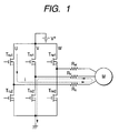
- Fig. 1 is a schematic circuit diagram for explaining the correction method according to the related art.
- Transistors Tr u1 , Tr u2 , Tr v1 , Tr v2 , Tr w1 , and Tr w2 are provided for the respective U, V, and W phases and constitute an inverter circuit.
- the transistors drive a three-phase electric motor M by means of a variable-voltage/variable-duty output, which is obtained by switching an output from a direct-current power supply V+.
- R u , R v , and R w denote resistors, which constitute the current detectors for the respective phase.
- Fig. 1 shows a case where a predetermined current "i" is caused to flow only in the reference phase (U) and another phase (V) to obtain outputs of the current detectors for U phase and V phase at this time.
- Fig. 2 is a diagram showing another configuration for obtaining a detected current value of each phase for the purpose of correcting the current value detected by the current detector, and showing a case where a detected current value of U phase among the three phases is obtained.
- Transistors T ru1 and T ru2 are transistors provided for the U-phase of the inverter circuit.
- a predetermined current is supplied from a constant current supply source.
- the current is detected by the resistor R u constituting the current detector; amplified by an amplifier Amp; and output to a microcomputer, where the current is subjected to A/D conversion. Correction is made on the basis of the thus-converted detected current value.
- correction is made by means of generating, for instance, a specific state where a predetermined current is caused to flow only in an arbitrary phase at the time of correcting a detected current value.
- a current detector includes a resistor and an amplifier. However, each element involves individual variation. Therefore, even if one and the same current value is detected, current values detected by detectors may vary.
- the invention provides an apparatus and a method for correcting detected current values of a three-phase electric motor by means of making correction to improve relative accuracy among current detectors, without using a special device.
- an apparatus corrects a current value of a three-phase electric motor including a current detector that detects current of each of three phase including a first phase, a second phase, and a third phase.
- the apparatus includes a current-value correcting unit. When current of one of the first to third phase is zero-crossing, the current-value correcting unit corrects a current value of at least one of the others of the first to third phases on a basis of a correlation between detection values of the current detectors provided for the others of the first to third phases during a period in which the three-phase electric motor is operating.
- the current-value correcting unit may correct the current value of the at least one of the second phase and the third phase on a basis of one of (a) a correlation between the detection values of the current detectors provided for the second and third phases at a time of the zero-cross of the current of the first phases in a course of rising and (b) a correlation between the detection values of the current detectors provided for the second and thirdphases at a time of the zero-cross of the current of the first phases in a course of falling.
- the current-value correcting unit may obtain the detection values of the current detectors provided for the second and third phases when a current value of the three-phase electric motor is equal to a first value, a second value or a third value.
- the apparatus may further include a storage unit that stores detection values of the current detectors provided for the respective first, second and third phases when current of the three-phase electric motor is equal to 0 ampere.
- the current-value correcting unit determines that the one of the three phases is zero-crossing.
- a method for correcting a current value of a three-phase electric motor including a current detector that detects current of each of three phases including a first phase, a second phase, and a third phase
- the method includes, when current of one of the first to third phase is zero-crossing, correcting a current value of at least one of the others of the first to third phases on a basis of a correlation between detection values of the current detectors provided for the others of the first to third phases during a period in which the three-phase electric motor is operating.
- the detected current values of the three-phase electric motor are relatively corrected, the detected current values, which vary to due to variations of the current detectors, can be corrected without using a special device. Therefore, the correction can be made easily.
- the correction of the detected current values does not require generation of a specific state, such as a state where a predetermined current is caused to flow only in a specific phase. Therefore, for instance, even after shipment of a product, such as a power steering system, equipped with a three-phase electric motor, detected current values can be corrected as required so long as the product is in use. Accordingly, a correction process may be eliminated from a pre-shipment inspection of the product.
- detected current values can be corrected as required so long as the product is in use, whereby the detected current values can be corrected in accordance with the individual variations even after shipment of the product.
- Fig. 3 is a view showing an overview of configuration of a control circuit for a three-phase electric motor.
- a correcting method according to an embodiment of the invention is applied to the control circuit.
- Transistors T ru1 , T ru2 , T rv1 , T rv2 , T rw1 , and T rw2 provided for the respective phases of U, V, and W, constitute an inverter circuit; and drive a three-phase electric motor M by means of variable-voltage/variable-duty outputs obtained by switching an output from a direct-current power supply V+. Meanwhile, control of these operations is exercised by a microcomputer 1.
- R u , R v , and R w are resistors, which constitute current detectors for the respective phases. Currents flowing in the respective phases are detected by these resistors; are amplified by amplifiers A u , A v , and A w for the respective phases and output to the microcomputer 1, where the thus-detected currents are subjected to A/D conversion; and stored in a storage device 2.
- amplifiers A v and A w are omitted.
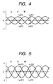
- Fig. 4 is a waveform diagram showing a three-phase alternating current, for explaining the correcting method according to this embodiment of the invention.
- Fig. 4 shows a waveform where a level of a current value of the motor is relatively low.
- a current value of one phase when a current value of one phase is 0, absolute values of current values of the two remaining phases are equal to each other.
- is equal to an absolute value of a V-phase current value
- is equal to an absolute value of a V-phase current value
- a zero-cross timing of the W-phase is a time point when the detected current value of W phase is equal to a stored current value (DI w ), which is a detected and stored current value of W phase when current of the three-phase electric motor --which will be described later ⁇ is 0 ampere.
- DI w stored current value
- DI u and DI v a time point when the detected current value of each of U and V phases is equal to each of the stored values DI u and DI v is the zero-cross timing of each of the U-phase and V-phase.
- Fig. 5 shows a waveform where a current value level of a motor is relatively medium.
- a current value of one phase when a current value of one phase is 0, absolute values of current values of the two remaining phases are equal to each other.
- a W-phase current value when a current value of one phase is 0, absolute values of current values of the two remaining phases are equal to each other.
- is equal to an absolute value of a V-phase current value
- is equal to an absolute value of a V-phase current value
- a zero-cross timing of the W-phase is a time point when the detected current value of W phase is equal to the stored current value (DI w ), which is the detected and stored current value of W phase when current of the three-phase electric motor M ⁇ which will be described later ⁇ is 0 ampere.
- DI w stored current value
- DI u and DI v a time point when the detected current value of each of U and V phases is equal to each of the stored values DI u and DI v is the zero-cross timing of each of the U-phase and V-phase.
- Fig. 6 shows a waveform where a level of a current value of the motor M is relatively high.
- a current value of one phase when a current value of one phase is 0, absolute current values of the two remaining phases are equal to each other.
- a W-phase current value when a current value of one phase is 0, absolute current values of the two remaining phases are equal to each other.
- is equal to an absolute of a V-phase current value
- is equal to an absolute value of a V-phase current value
- a zero-cross timing of the W-phase is a time point when the detected current value of W phase is equal to the stored current value (DI w ), which is the detected and stored current value of Wphase when current of the three-phase electric motor M ⁇ which will be described later ⁇ is 0 ampere.
- DI w stored current value
- DI u and DI v a time point when the detected current value of each of U and V phases is equal to each of the stored values DI u and DI v is the zero-cross timing of each of the U-phase and V-phase.
- Fig. 7 is a flowchart for explaining the correcting method according to this embodiment of the invention.
- the control performed in the flowchart is executed by the microcomputer 1 shown in Fig. 3.
- the flowchart will be described by reference to Fig. 3.
- the correcting method uses one of the three phases as a reference phase, and when a current value of one of the remaining two phases is zero-crossing, corrects a detected current value of the other of the remaining two phases to be equal to a detected current value of the reference value. Furthermore, when the other of the remaining two phases is zero crossing, the correcting method corrects the detected current value of the one of the remaining two phases to be equal to a detected current value of the reference value. According to this method, the detected current value of the remaining two phases can be corrected to be equal to the detected current values of the reference phase, thereby resolving offset errors.
- U phase is used as a reference phase.
- another phase is used as a reference phase, similar correction for detected current values can be made.
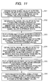
- Fig. 11 is a flowchart explaining the correcting method according to the second embodiment of the invention.
- the control performed in the flowchart is executed by the microcomputer 1 shown in Fig. 3.
- the flowchart will be described by reference to Fig. 3.
- step 11 outputs of the current detectors for the respective phases when the motor current is 0 ampere; that is, when the motor is not energized, are obtained as offset errors.
- Current values at this time are detected via the resistors R u , R v , and R w constituting the current detectors.
- the detected current values I u , I v , and I w which have been amplified by the amplifiers (Amp) A u , A v , and A w for the respective phases, are output to the microcomputer 1.
- the microcomputer 1 performs A/D conversion of the detected current values I u , I v , and I w , thereby obtaining digital signals DI u , DI v , and DI w , which indicate offset errors of the current detectors for the respective phases. Subsequently, the thus-obtained digital signals DI u , DI v , and DI w are stored in the storage device 2.
- the storage device 2 is implemented by, for instance, EE-PROM.
- step 12 detected current values of the current detectors for the U Phase and the V phase at the time of zero-crossing of the W-phase current are obtained.
- the motor is driven, and when a level of a current value is relatively low as shown in Fig. 4, current values I us (t1) and I us (t2) detected by the current detector for the U phase, and I vs (t1) and I vs (t2) detected by the current detector for the V phase, at the time of zero-crossing of the W-phase current, are output to the microcomputer 1.
- the microcomputer 1 performs A/D conversion of the detected current values I us (t1), I us (t2), I vs (t1), and I vs (t2), thereby obtaining digital signal values DI us (t1), DI us (t2), DI vs (t1), and DI vs (t2).
- the thus-obtained signal values are stored in the storage device 2.
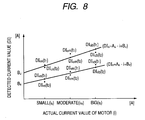
- step S13 correlation between the thus-obtained detected current values is obtained. More specifically, as shown in Fig. 8, absolute values of the digital signals ⁇ obtained through A/D conversion of the detected current values ⁇ are plotted in coordinates, which show actual current values of the motor M on the X axis and current values detected by the detectors on the Y axis.
- DI u A u ⁇ I + B u where B u is a value detected when the U-phase current is 0 ampere, and corresponds to an offset error.
- DI v A v ⁇ I + B v where B v is a value detected when the V-phase current is 0 ampere, and corresponds to an offset error.
- the V-phase detected value can be corrected to be the same value as the detected current value of the U phase, which is the reference phase.
- step 14 detected current values of the current detectors for the U Phase and the W phase at the time of zero-crossing of the V-phase current are obtained.
- the motor is driven, and when the level of the current value is relatively low as shown in Fig. 4, current values I us (t1) and I us (t2) detected by the current detector for the U phase, and I ws (t1) and I ws (t2) detected by the current detector for the V phase, at the time of zero-crossing of the V-phase current, are output to the microcomputer 1.
- the microcomputer 1 performs A/D conversion of the detected current values I us (t1), I us (t2), I ws (t1), and I ws (t2), thereby obtaining digital signal values DI us (t1), DI us (t2), DI ws (t1), and DI ws (t2).
- the thus-obtained signal values are stored in the storage device 2.
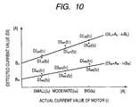
- step S15 correlation between the thus-obtained detected current values is obtained. More specifically, as shown in Fig. 8, absolute values of the digital signals ⁇ obtained through A/D conversion of the detected current values ⁇ are plotted in coordinates, which show actual current values of the motor M on the X axis and current values detected by the detectors on the Y axis.
- DI u A u ⁇ I + B u where B u is a value detected when the U-phase current is 0 ampere, and corresponds to an offset error.
- DI w A w ⁇ I + B w where B w is a value detected when the V-phase current is 0 ampere, and corresponds to an offset error.
- the V-phase detected value can be corrected to be the same value as the detected current value of the U phase, which is the reference phase.
- step 16 the control of the electric motor is executed with using the detected current values obtained from the equations (1), (4) and (7).
- a detected current value is corrected on the basis of the above equations and absolute values of the corrected current values of the remaining two phases are made equal to each other. As a result, relative accuracy of the detected current values are enhanced.
- the invention can be applied to any device, so long as a device has a three-phase electric motor.
- the invention is applied to a power steering apparatus for assisting steering operation of a vehicle by means of a three-phase electric motor, whereby a smooth, torque-ripple-free steering operation canbeprovided to a user.
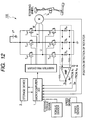
- Fig. 12 is a view showing an overview of configuration of a control circuit for a power steering apparatus 100 to which the correcting method of the embodiment of the invention is applied.
- Fig. 12 shows the circuit shown in Fig. 3 in more detail.
- the circuit shown in Fig. 3 is applied to the power steering apparatus 100.
- the power steering apparatus 100 includes a three-phase electric motor M and a control circuit therefor, which are similar to those shown in Fig. 3.
- the FETs Tru1, Tru2, Trv1, Trv2, Trw1, Trw2 in Fig. 12 may be of N-channel FETs, each of which is turned on when a gate voltage thereof is higher than a source voltage thereof.
- Each of FETs Tru1, Tru2, Trv1, Trv2, Trw1, Trw2 is connected to a diode in parallel.
- the power steering apparatus 100 also includes a position detection sensor 102, which detects a position of the rotator 101.
- the microcomputer 1 is connected to the position detection sensor 102, a torque sensor, a speed sensor, the amplifiers Au, Av, Aw and an inverter pre-driver. It is assumed that the U phase is used as a reference phase.
- the microcomputer 1 corrects a detected current value of the V phase so that an absolute value of the corrected current value of the V phase is equal to an absolute value of a current value of the U phase.
- the microcomputer 1 corrects a detected current value of the W phase so that an absolute value of the corrected current value of the W phase is equal to an absolute value of the U phase.
- the microcomputer 1 When controlling the power steering apparatus 100, the microcomputer 1 also utilizes a steering torque signal from the torque sensor, a speed signal from the speed sensor, and a position signal from the position detection sensor 102.
Landscapes
- Engineering & Computer Science (AREA)
- Chemical & Material Sciences (AREA)
- Combustion & Propulsion (AREA)
- Transportation (AREA)
- Mechanical Engineering (AREA)
- Control Of Ac Motors In General (AREA)
Applications Claiming Priority (1)
| Application Number | Priority Date | Filing Date | Title |
|---|---|---|---|
| JP2004182943 | 2004-06-21 |
Publications (3)
| Publication Number | Publication Date |
|---|---|
| EP1635449A2 true EP1635449A2 (de) | 2006-03-15 |
| EP1635449A3 EP1635449A3 (de) | 2006-03-22 |
| EP1635449B1 EP1635449B1 (de) | 2010-12-01 |
Family
ID=35058961
Family Applications (1)
| Application Number | Title | Priority Date | Filing Date |
|---|---|---|---|
| EP05253835A Expired - Lifetime EP1635449B1 (de) | 2004-06-21 | 2005-06-21 | Gerät zum Korrigieren der Stromwerte eines Drehstrommotors und ein Korrektur-Verfahren |
Country Status (3)
| Country | Link |
|---|---|
| US (1) | US7126305B2 (de) |
| EP (1) | EP1635449B1 (de) |
| DE (1) | DE602005025068D1 (de) |
Cited By (1)
| Publication number | Priority date | Publication date | Assignee | Title |
|---|---|---|---|---|
| DE102008011164B4 (de) * | 2008-02-26 | 2012-10-04 | Panasonic Industrial Devices Europe Gmbh | Verfahren und Vorrichtung zur dynamischen Kompensation der Nullpunktabweichung bei der Wicklungsstromerfassung für die Steuerung eines bürstenlosen Motors |
Families Citing this family (7)
| Publication number | Priority date | Publication date | Assignee | Title |
|---|---|---|---|---|
| KR100707419B1 (ko) * | 2004-12-03 | 2007-04-13 | 엘지전자 주식회사 | 상불평형 해소가 가능한 공기조화기 발전시스템 및 그상불평형 해소방법 |
| DE102008018075B4 (de) * | 2008-04-09 | 2010-12-23 | Sew-Eurodrive Gmbh & Co. Kg | Umrichter und Verfahren zur Bestimmung eines Stromraumzeigers |
| KR101288196B1 (ko) * | 2011-09-09 | 2013-07-19 | 삼성전기주식회사 | 초기 보정 기능을 갖는 모터 구동 장치 및 방법 |
| KR101539862B1 (ko) * | 2013-11-13 | 2015-07-27 | 삼성전기주식회사 | 모터 구동 제어 장치 및 방법, 그를 이용한 모터 시스템 |
| NZ630743A (en) | 2014-01-17 | 2016-05-27 | Resmed Motor Technologies Inc | Switched reluctance motor |
| WO2018203393A1 (ja) * | 2017-05-02 | 2018-11-08 | 三菱電機株式会社 | 電動機の制御装置、及び、電動パワーステアリングシステム |
| JP7234737B2 (ja) * | 2019-03-28 | 2023-03-08 | 株式会社デンソー | 検出ユニット |
Family Cites Families (7)
| Publication number | Priority date | Publication date | Assignee | Title |
|---|---|---|---|---|
| JPH0591780A (ja) | 1991-09-27 | 1993-04-09 | Japan Steel Works Ltd:The | 3相電動機の制御方法および装置 |
| JP3019245B2 (ja) | 1995-06-27 | 2000-03-13 | 本田技研工業株式会社 | 電動パワーステアリング装置 |
| JP3026949B2 (ja) * | 1997-05-12 | 2000-03-27 | ファナック株式会社 | エンコーダのオフセット補正回路 |
| DE10063054A1 (de) | 2000-12-18 | 2002-06-20 | Wilo Gmbh | Sensorloses Ansteuerverfahren |
| JP2002204581A (ja) * | 2001-01-09 | 2002-07-19 | Fuji Electric Co Ltd | 電力用半導体モジュール |
| JP3854190B2 (ja) | 2002-04-26 | 2006-12-06 | 株式会社ジェイテクト | モータ制御装置 |
| JP2003333882A (ja) * | 2002-05-14 | 2003-11-21 | Toyota Motor Corp | 多相モータ用制御装置 |
-
2005
- 2005-06-21 DE DE602005025068T patent/DE602005025068D1/de not_active Expired - Lifetime
- 2005-06-21 US US11/156,483 patent/US7126305B2/en not_active Expired - Fee Related
- 2005-06-21 EP EP05253835A patent/EP1635449B1/de not_active Expired - Lifetime
Cited By (1)
| Publication number | Priority date | Publication date | Assignee | Title |
|---|---|---|---|---|
| DE102008011164B4 (de) * | 2008-02-26 | 2012-10-04 | Panasonic Industrial Devices Europe Gmbh | Verfahren und Vorrichtung zur dynamischen Kompensation der Nullpunktabweichung bei der Wicklungsstromerfassung für die Steuerung eines bürstenlosen Motors |
Also Published As
| Publication number | Publication date |
|---|---|
| DE602005025068D1 (de) | 2011-01-13 |
| US20060001394A1 (en) | 2006-01-05 |
| EP1635449B1 (de) | 2010-12-01 |
| EP1635449A3 (de) | 2006-03-22 |
| US7126305B2 (en) | 2006-10-24 |
Similar Documents
| Publication | Publication Date | Title |
|---|---|---|
| US8901863B2 (en) | Motor control device | |
| US9667179B2 (en) | Multi-phase motor control apparatus and electric power steering apparatus using the same | |
| JP5328592B2 (ja) | モータ駆動装置 | |
| US10286949B2 (en) | Electric power steering apparatus | |
| US7889978B2 (en) | Motor controller and electric power steering system | |
| US9331612B2 (en) | Motor control apparatus | |
| US7336047B2 (en) | Motor vehicle steering system | |
| US20070296371A1 (en) | Position sensorless control apparatus for synchronous motor | |
| EP3020615B1 (de) | Elektrische servolenkvorrichtung | |
| EP1635449B1 (de) | Gerät zum Korrigieren der Stromwerte eines Drehstrommotors und ein Korrektur-Verfahren | |
| US9707993B2 (en) | Electric power steering apparatus | |
| EP2066018A2 (de) | Motorsteuervorrichtung | |
| US8760104B2 (en) | Determining average current drawn by a motor | |
| US9397554B2 (en) | Motor drive device having function of estimating dead time in output stage | |
| JP4760118B2 (ja) | 電動機の制御装置 | |
| JP2013121204A (ja) | モータ制御装置 | |
| JP2006042590A (ja) | 三相電動機の検出電流値補正装置及び補正方法 | |
| JP7267543B2 (ja) | 電流検出回路の調整方法 | |
| JP2008278646A (ja) | 電動パワーステアリング装置 | |
| JP2688370B2 (ja) | インバータ制御装置 | |
| JP6035190B2 (ja) | モータ制御装置 | |
| JPH03235697A (ja) | モータ駆動装置 | |
| JP2004328913A (ja) | 電流検出回路 | |
| JPH08223988A (ja) | モータの制御装置 |
Legal Events
| Date | Code | Title | Description |
|---|---|---|---|
| PUAI | Public reference made under article 153(3) epc to a published international application that has entered the european phase |
Free format text: ORIGINAL CODE: 0009012 |
|
| PUAL | Search report despatched |
Free format text: ORIGINAL CODE: 0009013 |
|
| AK | Designated contracting states |
Kind code of ref document: A2 Designated state(s): AT BE BG CH CY CZ DE DK EE ES FI FR GB GR HU IE IS IT LI LT LU MC NL PL PT RO SE SI SK TR |
|
| AX | Request for extension of the european patent |
Extension state: AL BA HR LV MK YU |
|
| AK | Designated contracting states |
Kind code of ref document: A3 Designated state(s): AT BE BG CH CY CZ DE DK EE ES FI FR GB GR HU IE IS IT LI LT LU MC NL PL PT RO SE SI SK TR |
|
| AX | Request for extension of the european patent |
Extension state: AL BA HR LV MK YU |
|
| 17P | Request for examination filed |
Effective date: 20060518 |
|
| AKX | Designation fees paid |
Designated state(s): DE FR GB |
|
| 17Q | First examination report despatched |
Effective date: 20091112 |
|
| GRAP | Despatch of communication of intention to grant a patent |
Free format text: ORIGINAL CODE: EPIDOSNIGR1 |
|
| GRAS | Grant fee paid |
Free format text: ORIGINAL CODE: EPIDOSNIGR3 |
|
| GRAA | (expected) grant |
Free format text: ORIGINAL CODE: 0009210 |
|
| AK | Designated contracting states |
Kind code of ref document: B1 Designated state(s): DE FR GB |
|
| REG | Reference to a national code |
Ref country code: GB Ref legal event code: FG4D |
|
| REF | Corresponds to: |
Ref document number: 602005025068 Country of ref document: DE Date of ref document: 20110113 Kind code of ref document: P |
|
| PLBE | No opposition filed within time limit |
Free format text: ORIGINAL CODE: 0009261 |
|
| STAA | Information on the status of an ep patent application or granted ep patent |
Free format text: STATUS: NO OPPOSITION FILED WITHIN TIME LIMIT |
|
| 26N | No opposition filed |
Effective date: 20110902 |
|
| REG | Reference to a national code |
Ref country code: DE Ref legal event code: R097 Ref document number: 602005025068 Country of ref document: DE Effective date: 20110902 |
|
| REG | Reference to a national code |
Ref country code: FR Ref legal event code: PLFP Year of fee payment: 11 |
|
| PGFP | Annual fee paid to national office [announced via postgrant information from national office to epo] |
Ref country code: GB Payment date: 20150617 Year of fee payment: 11 Ref country code: DE Payment date: 20150616 Year of fee payment: 11 |
|
| PGFP | Annual fee paid to national office [announced via postgrant information from national office to epo] |
Ref country code: FR Payment date: 20150608 Year of fee payment: 11 |
|
| REG | Reference to a national code |
Ref country code: DE Ref legal event code: R119 Ref document number: 602005025068 Country of ref document: DE |
|
| GBPC | Gb: european patent ceased through non-payment of renewal fee |
Effective date: 20160621 |
|
| REG | Reference to a national code |
Ref country code: FR Ref legal event code: ST Effective date: 20170228 |
|
| PG25 | Lapsed in a contracting state [announced via postgrant information from national office to epo] |
Ref country code: DE Free format text: LAPSE BECAUSE OF NON-PAYMENT OF DUE FEES Effective date: 20170103 Ref country code: FR Free format text: LAPSE BECAUSE OF NON-PAYMENT OF DUE FEES Effective date: 20160630 |
|
| PG25 | Lapsed in a contracting state [announced via postgrant information from national office to epo] |
Ref country code: GB Free format text: LAPSE BECAUSE OF NON-PAYMENT OF DUE FEES Effective date: 20160621 |