EP1635019B1 - Ensemble ferrure pour fenêtre, porte ou similaire - Google Patents
Ensemble ferrure pour fenêtre, porte ou similaire Download PDFInfo
- Publication number
- EP1635019B1 EP1635019B1 EP05017157A EP05017157A EP1635019B1 EP 1635019 B1 EP1635019 B1 EP 1635019B1 EP 05017157 A EP05017157 A EP 05017157A EP 05017157 A EP05017157 A EP 05017157A EP 1635019 B1 EP1635019 B1 EP 1635019B1
- Authority
- EP
- European Patent Office
- Prior art keywords
- push rod
- guide
- rod element
- fitting assembly
- assembly according
- Prior art date
- Legal status (The legal status is an assumption and is not a legal conclusion. Google has not performed a legal analysis and makes no representation as to the accuracy of the status listed.)
- Active
Links
- 238000006073 displacement reaction Methods 0.000 claims description 13
- 230000005540 biological transmission Effects 0.000 claims 1
- 230000000717 retained effect Effects 0.000 claims 1
- 210000001331 nose Anatomy 0.000 description 15
- 230000000712 assembly Effects 0.000 description 9
- 238000000429 assembly Methods 0.000 description 9
- 101100390736 Danio rerio fign gene Proteins 0.000 description 4
- 101100390738 Mus musculus Fign gene Proteins 0.000 description 4
- 238000009434 installation Methods 0.000 description 4
- 238000003780 insertion Methods 0.000 description 3
- 230000037431 insertion Effects 0.000 description 3
- 238000007789 sealing Methods 0.000 description 3
- 230000008878 coupling Effects 0.000 description 1
- 238000010168 coupling process Methods 0.000 description 1
- 238000005859 coupling reaction Methods 0.000 description 1
- 238000004519 manufacturing process Methods 0.000 description 1
Images


Classifications
-
- E—FIXED CONSTRUCTIONS
- E05—LOCKS; KEYS; WINDOW OR DOOR FITTINGS; SAFES
- E05C—BOLTS OR FASTENING DEVICES FOR WINGS, SPECIALLY FOR DOORS OR WINDOWS
- E05C9/00—Arrangements of simultaneously actuated bolts or other securing devices at well-separated positions on the same wing
- E05C9/24—Means for transmitting movements between vertical and horizontal sliding bars, rods or cables for the fastening of wings, e.g. corner guides
-
- E—FIXED CONSTRUCTIONS
- E05—LOCKS; KEYS; WINDOW OR DOOR FITTINGS; SAFES
- E05C—BOLTS OR FASTENING DEVICES FOR WINGS, SPECIALLY FOR DOORS OR WINDOWS
- E05C9/00—Arrangements of simultaneously actuated bolts or other securing devices at well-separated positions on the same wing
- E05C9/20—Coupling means for sliding bars, rods, or cables
-
- E—FIXED CONSTRUCTIONS
- E05—LOCKS; KEYS; WINDOW OR DOOR FITTINGS; SAFES
- E05D—HINGES OR SUSPENSION DEVICES FOR DOORS, WINDOWS OR WINGS
- E05D15/00—Suspension arrangements for wings
- E05D15/06—Suspension arrangements for wings for wings sliding horizontally more or less in their own plane
- E05D15/0621—Details, e.g. suspension or supporting guides
- E05D15/066—Details, e.g. suspension or supporting guides for wings supported at the bottom
- E05D15/0665—Details, e.g. suspension or supporting guides for wings supported at the bottom on wheels with fixed axis
-
- E—FIXED CONSTRUCTIONS
- E05—LOCKS; KEYS; WINDOW OR DOOR FITTINGS; SAFES
- E05D—HINGES OR SUSPENSION DEVICES FOR DOORS, WINDOWS OR WINGS
- E05D15/00—Suspension arrangements for wings
- E05D15/06—Suspension arrangements for wings for wings sliding horizontally more or less in their own plane
- E05D15/0621—Details, e.g. suspension or supporting guides
- E05D15/066—Details, e.g. suspension or supporting guides for wings supported at the bottom
- E05D15/0691—Top guides
-
- E—FIXED CONSTRUCTIONS
- E05—LOCKS; KEYS; WINDOW OR DOOR FITTINGS; SAFES
- E05Y—INDEXING SCHEME ASSOCIATED WITH SUBCLASSES E05D AND E05F, RELATING TO CONSTRUCTION ELEMENTS, ELECTRIC CONTROL, POWER SUPPLY, POWER SIGNAL OR TRANSMISSION, USER INTERFACES, MOUNTING OR COUPLING, DETAILS, ACCESSORIES, AUXILIARY OPERATIONS NOT OTHERWISE PROVIDED FOR, APPLICATION THEREOF
- E05Y2900/00—Application of doors, windows, wings or fittings thereof
- E05Y2900/10—Application of doors, windows, wings or fittings thereof for buildings or parts thereof
- E05Y2900/13—Type of wing
- E05Y2900/132—Doors
-
- E—FIXED CONSTRUCTIONS
- E05—LOCKS; KEYS; WINDOW OR DOOR FITTINGS; SAFES
- E05Y—INDEXING SCHEME ASSOCIATED WITH SUBCLASSES E05D AND E05F, RELATING TO CONSTRUCTION ELEMENTS, ELECTRIC CONTROL, POWER SUPPLY, POWER SIGNAL OR TRANSMISSION, USER INTERFACES, MOUNTING OR COUPLING, DETAILS, ACCESSORIES, AUXILIARY OPERATIONS NOT OTHERWISE PROVIDED FOR, APPLICATION THEREOF
- E05Y2900/00—Application of doors, windows, wings or fittings thereof
- E05Y2900/10—Application of doors, windows, wings or fittings thereof for buildings or parts thereof
- E05Y2900/13—Type of wing
- E05Y2900/148—Windows
Definitions
- the invention relates to a fitting arrangement of a window, a door or the like according to the preamble of claim 1.
- Fitting arrangements are often arranged at the fold side in the case of a window or a door or the like. As a result of such fitting arrangements, forces or movements introduced by a control element must generally be transferred to fitting parts along the fold of the window or the door.
- a fitting assembly on a wing or fixed enclosure of the window or door, with a guide fixed to the wing or fixed enclosure is arranged and a push rod member is movable relative to this guide.
- the push rod element is guided in or on the guide.
- On the push rod element one or more fitting parts are arranged through which a certain function is performed.
- a plurality of fitting parts must be arranged on the push rod element and coupled with it in motion. For this purpose, it is known, for example, to screw fitting parts on the push rod element. This is associated with a considerable installation effort.
- Object of the present invention is to provide a fitting assembly that can be mounted with little use of tools.
- a fitting arrangement of the type mentioned in which both the push rod element and the nose of at least one leg portion of the legs are engaged behind.
- the fitting part does not have to be connected directly to the push rod element. It may sit relatively loosely in or on the push rod member during assembly or assembly of the fitting assembly.
- the fitting part can be inserted with its nose in the recess.
- the fitting part is held in the assembled state by the guide on the push rod element.
- the fitting is simply placed for mounting on the push rod element, so that the nose protrudes into the recess and is inserted together with the push rod element in the guide. After insertion into the guide, the fitting is held by the legs of the guide. This makes a tool-free installation possible.
- the fitting part is arranged captive on the push rod element. Characterized in that the nose protrudes into the recess, the push rod member and the fitting part are also movement coupled.
- the cross-sectionally C-shaped guide may be formed as a C-profile.
- the cross-sectionally C-shaped guide is designed in several parts. In particular, it can be composed of two profiles which are U-shaped in cross-section. It is also conceivable to provide a fitting part as a guide which has at a distance from the groove bottom of the groove flanks protruding webs, which form the legs of the guide.
- the push rod element is generally movable between two end positions, ie within limits along the guide. It may therefore be sufficient not to form the legs completely along the guide, but to provide them only in those areas as leg sections in which the fitting parts are moved along the guide. In other words means This ensures that the lugs are held in engagement with the recesses in all possible movements of the push rod element.
- the strength of the nose preferably corresponds approximately to the strength of the push rod element.
- the thickness of the nose and a rear engagement portion of the push rod member are tuned approximately to the groove-like recess of the cross-sectionally C-shaped guide.
- the push rod member and the fitting part can be arranged substantially free of play in the guide.
- the dimensions of the nose are adapted to the recess.
- the fitting part in the direction of movement of the push rod element i. in the axial direction, arranged without play.
- the lugs can be arranged accurately in the recesses.
- a cross slide guide element may be provided which is mountable together with the push rod element in the C-shaped guide.
- a cross slide guide element must be stationary, in particular stationary with respect to the guide. This means that the push rod element must be displaceable relative to the cross slide guide element.
- the cross slide guide element is arranged with a holding portion behind the push rod element, can be fastened to the guide and engages with at least one guide means for a cross slide through opening of the push rod element.
- the cross slide guide element is arranged with a holding portion behind the push rod element. This means that in the assembled state, the holding portion between the push rod member and the C-shaped guide is arranged.
- the push rod element preferably has a slot through which the guide means projects. This ensures that the push rod element is movable relative to the cross slide guide element.
- a particularly simple assembly results when the cross slide guide element is clipped into the at least partially cross-sectionally C-shaped guide.
- the cross slide guide element can be introduced together with the push rod element and one or more fitting parts in the C-shaped guide. Subsequently, the cross slide guide element can be attached in a simple manner to the C-shaped guide, in which it is simply clipped into corresponding Klipsfactn. For this purpose, e.g. only a force on the cross slide guide element perpendicular to the extension of the guide necessary.
- the assembly is further simplified if the cross slide guide element has an alignment aid for alignment with respect to the push rod member during assembly of the fitting assembly.
- the alignment aid cooperates with a corresponding alignment aid of the push rod element and forms a displacement safety device in order to prevent unintentional axial displacement of the transverse slide guide element with respect to the push rod element during assembly.
- the anti-displacement prevents a displacement of the push rod member relative to the guide because of the fixed cross slide guide element.
- the alignment aids cooperate in such a way that they form a displacement safety device, the problem arises that after assembly the push rod element is immovable with respect to the transverse slide guide element.
- the anti-displacement device is destructible, in particular one of the alignment aids is designed to be sheared off.
- the alignment aid is stable enough to ensure the mutual alignment of the components during assembly. By a corresponding force entry, the anti-slip device can be solved. In a particularly simple manner, the anti-displacement device can be released when the alignment aid is removed.
- the alignment aid may be formed as a pin which projects into a trained as a recess alignment aid of the push rod member, and which is sheared by a movement of the push rod member.
- a transverse slide which is held on a sliding member designed as a longitudinal member and a control pin on the push rod element.
- the cross slide preferably has guide means, which are guided by corresponding guide means of the cross slide guide element.
- the cross slide is thereby displaced obliquely to the direction of movement of the push rod element.
- the longitudinal slide may be a fitting part which has a nose which projects into a corresponding recess of the push rod element.
- sealing elements of a seal assembly can be arranged so that the fitting assembly for controlling the seal assembly can be used to selectively open a gap between the window or door and a fixed enclosure for air passage or to close against air passage.
- the cross slide and / or the longitudinal slide on an orientation aid can be formed asymmetrically depending on the application.
- a mark can be provided, which indicates to the fitter how to properly install the longitudinal slide or the cross slide.
- the fitting arrangement can be used particularly easily in sliding doors.
- the carriage may be provided at the bottom end of the window or the door and the slider at the top.
- the carriage or the slider is screwed or clipped to the guide.
- the fitting assembly can be largely assembled without tools.
- the carriage or slider is bolted to the guide, the use of tools in assembly of the fitting assembly is minimized.
- the slider and the carriage are each secured only with a screw.
- a corner deflection is provided, which is connected to the push rod element.
- the fitting arrangement is used in a sliding door which has a controllable sealing arrangement in the horizontally extending fold area, a movement introduced on a control element often has to be transferred to the fitting arrangement for controlling the seal arrangement, the operating element being attached, for example, to a vertical bar of the door. or window sash is arranged.
- a movement introduced there can be particularly easily transmitted via a corner drive on a arranged in or on a horizontal bar of the door or window sash fitting arrangement.
- a plurality of assemblies are provided, wherein at least one assembly has an at least partially cross-sectionally C-shaped guide and a push rod element and the push rod element is coupled in motion with a push rod element of an adjacent module.
- the C-shaped guide does not have to extend along the entire width of the window or door. It is sufficient to provide a guide at the places where fitting parts are necessary.
- Assemblies can be assembled for different purposes and locations, with different assemblies can use the same or similar components.
- end assemblies may be provided in the corner regions of the window or the door and for bridging larger distances between the end assemblies may be provided intermediate modules, wherein the push rod elements of the assemblies are motion-coupled via connecting elements.
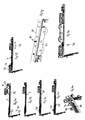
- the illustrated assembly 1 has a push rod element 2, which recesses 3, 4 contains.
- the push rod element 2 has passage openings 5, 6 formed as elongated holes.
- a transverse slide guide element 7 is pushed through the passage opening 6 with a first of two guide means 8, 9.
- the cross slide guide element 7 is aligned with respect to the push rod element 2 by inserting a detachable alignment aid 10 from behind into an alignment aid 11 of the push rod element 2 designed as a passage opening.
- Fig. 1b is shown how the cross slide guide element 7 is arranged on the push rod element 2.
- a holding portion 12 of the cross slide guide element 7 is located behind or below the push rod element 2.
- a designed as a longitudinal slide fitting 13 is placed, wherein a nose 14 is inserted into the recess 4 of the push rod element 2.
- the assembled fitting part 13 is coupled for movement with the push rod element 2.
- the fitting part 20 also has a nose 21, the dimensions of which are adapted to the recess 3.
- the cross slide 15 has a notch trained orientation aid 25, which ensures the correct installation of the cross slide 15. This is advantageous in particular in the case of asymmetrical control slot 17.
- Fig. 1d From Fig. 1d it can be seen that the entire arrangement consisting of push rod element 2, fittings 13, 20, cross slide guide element 7, cross slide 15 and control pin 16 are jointly introduced into a C-shaped cross-section C-shaped guide 28.
- the push rod member 2 In the inserted state engage behind the legs 29, 30 of the guide 28, which form a groove-like recess with the guide base 33, rear engagement portions 31 of the push rod member 2 and the lugs 14, 21.
- the push rod member 2 is formed step-shaped.
- the region 32 protrudes upwards beyond the engagement sections 31, so that a sufficiently large intermediate space remains between the region 32 and the base 33 of the guide 28 for the holding section 12 of the cross slide guide element 7.
- the cross slide guide element 7 can be fastened by clipping into the guide 28.
- clip portions 34, 35 are provided on the holding element 12, which clip into the associated clip receptacles of the guide 28 by corresponding pressure. If now the push rod element 2 is acted upon in the axial direction 36 with a force and thereby moved, the alignment aid 10 is sheared off. As a result, a relative movement of the push rod element 2 to the cross slide guide element 7 is possible.
- the assembly 1 is intended to be used in an upper end region of a sliding door. Therefore, a slider 38 is still mounted.
- the slider 38 should be arranged stationary with respect to the guide 28. Furthermore, he should not hinder the axial movement of the push rod element 2. Therefore, the trained as a slot 5 passage opening is provided, through which the slider 38 can be inserted with a mounting portion 39.
- the slider 38 is fastened in the exemplary embodiment via a screw connection 40.
- anti-rotation means which are designed as pins 41, 42, are provided, which protrude into corresponding receptacles of the guide 28.
- the push rod member 2 can be motion coupled to a push rod member of an adjacent assembly by attaching a connector to adjacent connectors of the two assemblies.
- the assembly 50 is intended for use in the lower end region of a sliding door. Components that correspond to components of the assembly 1 are designated by the same reference numerals. Since the assembly 50 is to be used at the lower end of a sliding door, the slider must be replaced by a carriage 51. The carriage 51 in turn has a mounting portion 52 which projects through the passage opening 5 and bolted from behind by means of a screw 40 with the guide 28 can be. A single screw 53 is sufficient, since a rotation of the carriage 51 is excluded. There protrude cones 41, 42 through corresponding openings of the guide 28. Through them, a rotation lock is realized. Since the assembly 50 is an end assembly, a single connector 20 component is sufficient for motion coupling with an adjacent assembly. The control slot 17 is formed differently than in the cross slide 15 of the assembly 1. This is related to the operation of each driven by the cross slide 15 seal assembly.
- the assembly of a designed as a center assembly of a fitting assembly assembly 60 is shown.
- the push rod element 2 has two recesses 3, 3a for lugs 21, 21a of components 20, 20a designed as connectors. Since the module 60 acts as a center module, a push rod element of an adjacent module must be coupled to the push rod element 2 on both sides in each case. Therefore, two components 20, 20a are provided.
- the adjacent assembly may be another center assembly or an end or corner assembly.
- the cross slide guide element 7 Before attaching the control unit, consisting of component 13, cross slide 15 and control pin 16, the cross slide guide element 7 is arranged from behind on the push rod element 2, wherein the first and second guide means 8, 9 designed as elongated holes Pass through openings 6, 6a.
- the alignment aid 10 engages in the alignment 11, so that when applying the control unit, the nose 14 automatically enters the recess 4 when the guide means 18, 19 are inserted into the guide means 8, 9.
- the entire still loosely assembled arrangement consisting of push rod element 2, components 20, 20a, control unit and cross slide guide element 7 is inserted together in a cross-sectionally C-shaped guide 28, whereby the components 20, 20a and 13 are held captive on the push rod 2.
- the cross slide guide element 7 is clipped to the guide 28.
- the cross slide guide element 7 is held immovably on the guide 28.
- the cross slide guide element 7 and the push rod element 2 are immovable relative to one another via the alignment aids 10, 11 which act as a displacement safeguard.
- the position of the push rod element 2 is fixed. It can not move unintentionally and the components 20, 20a, 13 can not "fall out” because the push rod element 2 can not slip out of the guide 28. Only when the assemblies 60 are mounted, for example, in a fitting part of a sash, the components 20, 20a are connected via a rigid connecting element with an adjacent assembly 60.
- the displacement lock ensures that when connecting adjacent components 20, 20a adjacent assemblies 60, the guide means 8, 9 in the middle in the Through openings 6, 6a are arranged. Only when all adjacent formed as a connector components 20, 20a are motion-coupled, the anti-displacement device is destroyed.
- the assembly of a designed as a corner assembly assembly 70 which can be arranged in the lower corner of a sliding door, is shown.
- the push rod element 2 is coupled for movement with a corner drive 71.
- a movement of the push rod member 72, which can be driven via a control handle is transmitted by a flexible push rod member 73 to the push rod member 2, wherein a deflection of the movement takes place from a vertical to a horizontal movement.
- the components 20, 13 and the cross slide guide element 7 are arranged on the push rod element 2. Subsequently, the entire assembly is inserted into a guide 28 (Fig. 4c).
- a longitudinal slide 75 is fastened to a connecting element 74 of the corner drive 71. Since a cross slide guide element 7 can not easily be attached in the corner region of the corner drive 71, a guide element 76 is arranged in the corner region, as shown in FIG. 4e. This guide element 76 engages, as can be seen in Fig. 4f, in a slot 77 of the cross slide 78 and holds it immovably fixed in the folding longitudinal direction 79.
- the cross slide 78 is placed on the longitudinal slide 75 and held on this via a control pin, which passes through a through hole 80.
- the push rod element 2 has a passage opening 5 for receiving the attachment portion of a carriage 51. This is fastened via a screw 40 to the guide 28.
- FIG. 5 an exploded view of a control device is shown.
- Trained as a longitudinal slide member 13 has a nose 14.
- Laterally U-shaped recesses 81, 82 are provided, which allow it to approach with the component 13 as close as possible to the guide means 18, 19 of the cross slide 15.
- the guide means 18, 19 are designed as pins, which can engage in corresponding formed as sleeves guide means of the cross slide guide element 7.
- the component 13 has a control pin receptacle 83 into which the control pin 16 can be inserted.
- the control pin 16 also passes through a control slot 17 in the cross slide 15. In axially fixed cross slide 15, therefore, a transverse movement of the cross slide 15 is generated by a longitudinal movement of the component 13.
- sealing elements of a seal assembly can be attached.
- the longitudinal slide 13 has a bearing surface 84 with which it can rest on the push rod element 2.
Landscapes
- Engineering & Computer Science (AREA)
- Mechanical Engineering (AREA)
- Window Of Vehicle (AREA)
- Power-Operated Mechanisms For Wings (AREA)
- Securing Of Glass Panes Or The Like (AREA)
- Connection Of Plates (AREA)
Claims (15)
- Ensemble de ferrure d'une fenêtre, d'une porte ou similaire, avec un guide (28) réalisé à section en forme de C au moins sur des tronçons, qui présente des branches (29, 30) dépassant des flancs de rainure à distance du fond de guide (33), avec un élément de bielle (2) guidé par le guide (28), et avec au moins une partie de ferrure (13, 20, 20a) couplée en déplacement à l'élément de bielle (2), sachant que l'élément de bielle (2) présente au moins un évidement (3, 4) et la partie de ferrure (13, 20, 20a) au moins un ergot (14, 21, 21a) faisant saillie dans l'évidement (3, 4), caractérisé en ce que tant l'élément de bielle (2) que l'ergot (14, 21, 21a) sont engagés en prise arrière par au moins un tronçon de branche des branches (29, 30).
- Ensemble de ferrure selon la revendication 1, caractérisé en ce que l'épaisseur de l'ergot (14, 21, 21a) correspond approximativement à l'épaisseur de l'élément de bielle (2).
- Ensemble de ferrure selon la revendication 1 ou 2, caractérisé en ce que les dimensions de l'ergot (14, 21, 21a) sont adaptées à l'évidement (3, 4).
- Ensemble de ferrure selon l'une des revendications précédentes, caractérisé en ce qu'il est prévu un élément (7) de guidage de poussoir transversal, qui peut être monté conjointement avec l'élément de bielle (2) dans le guide (28) à section en forme de C au moins sur des tronçons.
- Ensemble de ferrure selon la revendication 4, caractérisé en ce que l'élément (7) de guidage de poussoir transversal est disposé par un tronçon de maintien (12) derrière l'élément de bielle (2), peut être fixé sur le guide (28) et traverse par au moins un moyen de guidage (8, 9) pour un poussoir transversal (15) une ouverture de passage (6, 6a) de l'élément de bielle (2).
- Ensemble de ferrure selon la revendication 4 ou 5, caractérisé en ce que l'élément (7) de guidage de poussoir transversal est clipsé dans le guide (28) à section en forme de C au moins sur des tronçons.
- Ensemble de ferrure selon l'une des revendications précédentes 4 à 6, caractérisé en ce que l'élément (7) de guidage de poussoir transversal présente une aide à l'alignement (10) pour l'alignement par rapport à l'élément de bielle (2) pendant le montage de l'ensemble de ferrure.
- Ensemble de ferrure selon la revendication 7, caractérisé en ce que l'aide à l'alignement (10) coopère avec une aide à l'alignement correspondante (11) de l'élément de bielle (2) et forme un blocage en translation, afin d'empêcher une translation axiale de l'élément (7) de guidage de poussoir transversal par rapport à l'élément de bielle lors du montage.
- Ensemble de ferrure selon la revendication 8, caractérisé en ce que le blocage en translation est destructible, en particulier une des aides à l'alignement (10, 11) peut être cisaillée.
- Ensemble de ferrure selon l'une des revendications précédentes, caractérisé en ce qu'il est prévu un poussoir transversal (15) qui est maintenu sur l'élément de bielle (2) par l'intermédiaire d'une pièce (13) conçue comme poussoir longitudinal et d'un tenon de commande (16).
- Ensemble de ferrure selon la revendication 10, caractérisé en ce que le poussoir transversal (15) et/ou le poussoir longitudinal (13) présentent une aide à l'orientation (25).
- Ensemble de ferrure selon l'une des revendications précédentes, caractérisé en ce qu'un coulisseau (38) ou un chariot (51) est fixé sur le guide (28) à section en forme de C au moins sur des tronçons.
- Ensemble de ferrure selon la revendication 12, caractérisé en ce que le chariot (51) ou le coulisseau (38) est notamment fixé sur le guide (28) par vissage ou par clipsage.
- Ensemble de ferrure selon l'une des revendications précédentes, caractérisé en ce qu'il est prévu au moins un renvoi d'angle (71) qui est relié à l'élément de bielle (2).
- Ensemble de ferrure selon l'une des revendications précédentes, caractérisé en ce qu'il est prévu plusieurs sous-ensembles (1, 50, 60, 70), sachant qu'au moins un sous-ensemble présente un guide (28) à section en forme de C au moins sur des tronçons et un élément de bielle (2), et que l'élément de bielle (2) est couplé en déplacement à un élément de bielle (2) d'un sous-ensemble voisin (1, 50, 60, 70).
Priority Applications (1)
| Application Number | Priority Date | Filing Date | Title |
|---|---|---|---|
| PL05017157T PL1635019T5 (pl) | 2004-09-11 | 2005-08-06 | Układ okuć dla okna, drzwi lub temu podobnych |
Applications Claiming Priority (1)
| Application Number | Priority Date | Filing Date | Title |
|---|---|---|---|
| DE102004043942A DE102004043942A1 (de) | 2004-09-11 | 2004-09-11 | Beschlaganordnung für ein Fenster, eine Tür oder dergleichen |
Publications (4)
| Publication Number | Publication Date |
|---|---|
| EP1635019A2 EP1635019A2 (fr) | 2006-03-15 |
| EP1635019A3 EP1635019A3 (fr) | 2006-04-12 |
| EP1635019B1 true EP1635019B1 (fr) | 2007-10-17 |
| EP1635019B2 EP1635019B2 (fr) | 2013-10-23 |
Family
ID=35482598
Family Applications (1)
| Application Number | Title | Priority Date | Filing Date |
|---|---|---|---|
| EP05017157.8A Active EP1635019B2 (fr) | 2004-09-11 | 2005-08-06 | Ensemble ferrure pour fenêtre, porte ou similaire |
Country Status (4)
| Country | Link |
|---|---|
| EP (1) | EP1635019B2 (fr) |
| AT (1) | ATE376112T1 (fr) |
| DE (2) | DE102004043942A1 (fr) |
| PL (1) | PL1635019T5 (fr) |
Families Citing this family (1)
| Publication number | Priority date | Publication date | Assignee | Title |
|---|---|---|---|---|
| CA3093608A1 (fr) * | 2019-09-17 | 2021-03-17 | Truth Hardware Corporation | Armature de liaison et guide pour fenetre a battants |
Family Cites Families (13)
| Publication number | Priority date | Publication date | Assignee | Title |
|---|---|---|---|---|
| CH437727A (de) * | 1964-10-21 | 1967-06-15 | Gretsch Unitas Gmbh | Fensterflügelrahmen mit in mindestens einer Rahmenleiste längs verschiebbarer Schiene |
| AT322180B (de) † | 1971-04-15 | 1975-05-12 | Muehle Manfred | Halterung für eine riegelstange in einem rahmenprofil für fenster, türen od.dgl. |
| AT373342B (de) * | 1974-05-30 | 1984-01-10 | Winkhaus Fa August | Befestigungswinkel eines schubstangeneckumlenkers |
| DE2426030C2 (de) * | 1974-05-30 | 1986-09-11 | Winkhaus, August, 4404 Telgte | Ausstellvorrichtung für ein Drehkippfenster |
| DE3525705A1 (de) * | 1985-07-18 | 1987-01-22 | Winkhaus Fa August | Paarung von verriegelungselementen an einem fenster einer tuer oder dergleichen |
| FR2747150B1 (fr) * | 1996-04-04 | 1998-08-07 | Ferco Int Usine Ferrures | Cremone ou cremone-serrure, notamment du type multipoints |
| DE59912748D1 (de) * | 1998-03-25 | 2005-12-15 | Siegenia Aubi Kg | Beschlag für Fenster oder Türen |
| DE19853507C2 (de) † | 1998-11-20 | 2001-11-22 | Siegenia Frank Kg | Treibstangenbeschlag für Fenster, Türen od. dgl. |
| DE29920094U1 (de) † | 1999-11-15 | 2000-02-10 | Siegenia Frank Kg | Beschlag eines zumindest behebbaren, vorzugsweise aber auch bewegbaren Flügels eines Fensters oder einer Tür |
| IT1314886B1 (it) † | 2000-12-13 | 2003-01-16 | Euroinvest S R L | Collegamento meccanico d'uso all'interno di dispositivi di ancoraggioperimetrale di ante di infissi antieffrazione in profilato metallico |
| BE1014943A3 (nl) † | 2001-01-29 | 2004-07-06 | Parys Remi E Van | Beslag van een raam en onderdelen daarvoor. |
| ITTO20030488A1 (it) † | 2003-06-27 | 2004-12-28 | Savio Spa | Asta di trasmissione per accessori per serramenti |
| DE10345758B4 (de) † | 2003-10-01 | 2010-09-23 | Wicona Bausysteme Gmbh | Beschlag für den Flügelrahmen eines Fensters, einer Tür oder dergleichen |
-
2004
- 2004-09-11 DE DE102004043942A patent/DE102004043942A1/de not_active Withdrawn
-
2005
- 2005-08-06 PL PL05017157T patent/PL1635019T5/pl unknown
- 2005-08-06 AT AT05017157T patent/ATE376112T1/de active
- 2005-08-06 DE DE502005001709T patent/DE502005001709D1/de active Active
- 2005-08-06 EP EP05017157.8A patent/EP1635019B2/fr active Active
Also Published As
| Publication number | Publication date |
|---|---|
| DE102004043942A1 (de) | 2006-03-30 |
| PL1635019T3 (pl) | 2008-03-31 |
| EP1635019A2 (fr) | 2006-03-15 |
| ATE376112T1 (de) | 2007-11-15 |
| EP1635019B2 (fr) | 2013-10-23 |
| EP1635019A3 (fr) | 2006-04-12 |
| PL1635019T5 (pl) | 2014-03-31 |
| DE502005001709D1 (de) | 2007-11-29 |
Similar Documents
| Publication | Publication Date | Title |
|---|---|---|
| EP3165703A2 (fr) | Dispositif d'étanchéité abaissable | |
| DE2313690A1 (de) | Treibstangenbeschlag fuer fenster, tueren od.dgl | |
| WO2007014605A1 (fr) | Dispositif de bande pour portes, fenetres ou similaires | |
| EP3266969B1 (fr) | Renvoi d'angle d'une ferrure pour un battant de fenêtre ou de porte | |
| EP0843064B1 (fr) | Ferrure pour un fenêtre | |
| DE202008004032U1 (de) | Fenster oder Tür | |
| EP1635019B1 (fr) | Ensemble ferrure pour fenêtre, porte ou similaire | |
| EP1746235B1 (fr) | Ensemble de ferrure | |
| WO2020236099A1 (fr) | Ferrure de meuble | |
| EP1264954B1 (fr) | Système de verouillage | |
| DE3225049C2 (de) | Treibstangenverschluß | |
| EP2754803A2 (fr) | Crémone de fenêtre ou de porte | |
| DE19859546A1 (de) | Schieberstangenbefestigungs- und -führungselement | |
| AT403500B (de) | Beschlagteileverbindung | |
| EP2317047A2 (fr) | Agencement de ferrure | |
| EP3535824B1 (fr) | Support de jeu de barres et ensemble correspondant | |
| EP2439362B1 (fr) | Barre anti-panique à compression | |
| EP1580370B1 (fr) | Ensemble ferrure | |
| EP1626150B1 (fr) | Dispositif d'étanchéité | |
| WO2015074933A1 (fr) | Dispositif de retenue pour boîtier et procédé de montage du boîtier à l'aide du dispositif de retenue | |
| EP0833028A1 (fr) | Butée d'arrêt de glissière de guidage pour arrêt de fenêtre ou de porte | |
| DE4321616A1 (de) | Vorrichtung zum Verbinden eines Mitnehmers eines Fensterhebers mit einer Fensterscheibe | |
| EP4074931B1 (fr) | Ferrure dotée d'un crochet d'encliquetage pouvant être bloqué par coulissement longitudinal | |
| DE19734647B4 (de) | Beschlagteil an einem Flügel oder einem festen Rahmen eines Fensters, einer Tür od. dgl. | |
| EP1580371B1 (fr) | Ensemble ferrure |
Legal Events
| Date | Code | Title | Description |
|---|---|---|---|
| PUAI | Public reference made under article 153(3) epc to a published international application that has entered the european phase |
Free format text: ORIGINAL CODE: 0009012 |
|
| PUAL | Search report despatched |
Free format text: ORIGINAL CODE: 0009013 |
|
| AK | Designated contracting states |
Kind code of ref document: A2 Designated state(s): AT BE BG CH CY CZ DE DK EE ES FI FR GB GR HU IE IS IT LI LT LU LV MC NL PL PT RO SE SI SK TR |
|
| AX | Request for extension of the european patent |
Extension state: AL BA HR MK YU |
|
| AK | Designated contracting states |
Kind code of ref document: A3 Designated state(s): AT BE BG CH CY CZ DE DK EE ES FI FR GB GR HU IE IS IT LI LT LU LV MC NL PL PT RO SE SI SK TR |
|
| AX | Request for extension of the european patent |
Extension state: AL BA HR MK YU |
|
| 17P | Request for examination filed |
Effective date: 20060810 |
|
| AKX | Designation fees paid |
Designated state(s): AT BE BG CH CY CZ DE DK EE ES FI FR GB GR HU IE IS IT LI LT LU LV MC NL PL PT RO SE SI SK TR |
|
| GRAP | Despatch of communication of intention to grant a patent |
Free format text: ORIGINAL CODE: EPIDOSNIGR1 |
|
| GRAS | Grant fee paid |
Free format text: ORIGINAL CODE: EPIDOSNIGR3 |
|
| GRAA | (expected) grant |
Free format text: ORIGINAL CODE: 0009210 |
|
| AK | Designated contracting states |
Kind code of ref document: B1 Designated state(s): AT BE BG CH CY CZ DE DK EE ES FI FR GB GR HU IE IS IT LI LT LU LV MC NL PL PT RO SE SI SK TR |
|
| REG | Reference to a national code |
Ref country code: GB Ref legal event code: FG4D Free format text: NOT ENGLISH |
|
| REG | Reference to a national code |
Ref country code: CH Ref legal event code: EP |
|
| REG | Reference to a national code |
Ref country code: IE Ref legal event code: FG4D Free format text: LANGUAGE OF EP DOCUMENT: GERMAN |
|
| REF | Corresponds to: |
Ref document number: 502005001709 Country of ref document: DE Date of ref document: 20071129 Kind code of ref document: P |
|
| ET | Fr: translation filed | ||
| REG | Reference to a national code |
Ref country code: PL Ref legal event code: T3 |
|
| PG25 | Lapsed in a contracting state [announced via postgrant information from national office to epo] |
Ref country code: ES Free format text: LAPSE BECAUSE OF FAILURE TO SUBMIT A TRANSLATION OF THE DESCRIPTION OR TO PAY THE FEE WITHIN THE PRESCRIBED TIME-LIMIT Effective date: 20080128 Ref country code: SE Free format text: LAPSE BECAUSE OF FAILURE TO SUBMIT A TRANSLATION OF THE DESCRIPTION OR TO PAY THE FEE WITHIN THE PRESCRIBED TIME-LIMIT Effective date: 20080117 |
|
| GBV | Gb: ep patent (uk) treated as always having been void in accordance with gb section 77(7)/1977 [no translation filed] | ||
| PG25 | Lapsed in a contracting state [announced via postgrant information from national office to epo] |
Ref country code: PT Free format text: LAPSE BECAUSE OF FAILURE TO SUBMIT A TRANSLATION OF THE DESCRIPTION OR TO PAY THE FEE WITHIN THE PRESCRIBED TIME-LIMIT Effective date: 20080317 Ref country code: BG Free format text: LAPSE BECAUSE OF FAILURE TO SUBMIT A TRANSLATION OF THE DESCRIPTION OR TO PAY THE FEE WITHIN THE PRESCRIBED TIME-LIMIT Effective date: 20080117 Ref country code: SI Free format text: LAPSE BECAUSE OF FAILURE TO SUBMIT A TRANSLATION OF THE DESCRIPTION OR TO PAY THE FEE WITHIN THE PRESCRIBED TIME-LIMIT Effective date: 20071017 Ref country code: LV Free format text: LAPSE BECAUSE OF FAILURE TO SUBMIT A TRANSLATION OF THE DESCRIPTION OR TO PAY THE FEE WITHIN THE PRESCRIBED TIME-LIMIT Effective date: 20071017 Ref country code: IS Free format text: LAPSE BECAUSE OF FAILURE TO SUBMIT A TRANSLATION OF THE DESCRIPTION OR TO PAY THE FEE WITHIN THE PRESCRIBED TIME-LIMIT Effective date: 20080217 Ref country code: LT Free format text: LAPSE BECAUSE OF FAILURE TO SUBMIT A TRANSLATION OF THE DESCRIPTION OR TO PAY THE FEE WITHIN THE PRESCRIBED TIME-LIMIT Effective date: 20071017 |
|
| REG | Reference to a national code |
Ref country code: IE Ref legal event code: FD4D |
|
| PLBI | Opposition filed |
Free format text: ORIGINAL CODE: 0009260 |
|
| PG25 | Lapsed in a contracting state [announced via postgrant information from national office to epo] |
Ref country code: DK Free format text: LAPSE BECAUSE OF FAILURE TO SUBMIT A TRANSLATION OF THE DESCRIPTION OR TO PAY THE FEE WITHIN THE PRESCRIBED TIME-LIMIT Effective date: 20071017 |
|
| 26 | Opposition filed |
Opponent name: SIEGENIA-AUBI KG Effective date: 20080711 |
|
| PLAX | Notice of opposition and request to file observation + time limit sent |
Free format text: ORIGINAL CODE: EPIDOSNOBS2 |
|
| PG25 | Lapsed in a contracting state [announced via postgrant information from national office to epo] |
Ref country code: SK Free format text: LAPSE BECAUSE OF FAILURE TO SUBMIT A TRANSLATION OF THE DESCRIPTION OR TO PAY THE FEE WITHIN THE PRESCRIBED TIME-LIMIT Effective date: 20071017 Ref country code: RO Free format text: LAPSE BECAUSE OF FAILURE TO SUBMIT A TRANSLATION OF THE DESCRIPTION OR TO PAY THE FEE WITHIN THE PRESCRIBED TIME-LIMIT Effective date: 20071017 |
|
| PG25 | Lapsed in a contracting state [announced via postgrant information from national office to epo] |
Ref country code: IE Free format text: LAPSE BECAUSE OF FAILURE TO SUBMIT A TRANSLATION OF THE DESCRIPTION OR TO PAY THE FEE WITHIN THE PRESCRIBED TIME-LIMIT Effective date: 20071017 |
|
| PGFP | Annual fee paid to national office [announced via postgrant information from national office to epo] |
Ref country code: NL Payment date: 20080828 Year of fee payment: 4 |
|
| NLR1 | Nl: opposition has been filed with the epo |
Opponent name: SIEGENIA-AUBI KG |
|
| PG25 | Lapsed in a contracting state [announced via postgrant information from national office to epo] |
Ref country code: GB Free format text: LAPSE BECAUSE OF FAILURE TO SUBMIT A TRANSLATION OF THE DESCRIPTION OR TO PAY THE FEE WITHIN THE PRESCRIBED TIME-LIMIT Effective date: 20071017 |
|
| PLBB | Reply of patent proprietor to notice(s) of opposition received |
Free format text: ORIGINAL CODE: EPIDOSNOBS3 |
|
| PG25 | Lapsed in a contracting state [announced via postgrant information from national office to epo] |
Ref country code: GR Free format text: LAPSE BECAUSE OF FAILURE TO SUBMIT A TRANSLATION OF THE DESCRIPTION OR TO PAY THE FEE WITHIN THE PRESCRIBED TIME-LIMIT Effective date: 20080118 |
|
| PGFP | Annual fee paid to national office [announced via postgrant information from national office to epo] |
Ref country code: TR Payment date: 20080725 Year of fee payment: 4 |
|
| PG25 | Lapsed in a contracting state [announced via postgrant information from national office to epo] |
Ref country code: FI Free format text: LAPSE BECAUSE OF FAILURE TO SUBMIT A TRANSLATION OF THE DESCRIPTION OR TO PAY THE FEE WITHIN THE PRESCRIBED TIME-LIMIT Effective date: 20071017 |
|
| PGFP | Annual fee paid to national office [announced via postgrant information from national office to epo] |
Ref country code: BE Payment date: 20080908 Year of fee payment: 4 |
|
| PG25 | Lapsed in a contracting state [announced via postgrant information from national office to epo] |
Ref country code: MC Free format text: LAPSE BECAUSE OF NON-PAYMENT OF DUE FEES Effective date: 20080831 |
|
| PG25 | Lapsed in a contracting state [announced via postgrant information from national office to epo] |
Ref country code: EE Free format text: LAPSE BECAUSE OF FAILURE TO SUBMIT A TRANSLATION OF THE DESCRIPTION OR TO PAY THE FEE WITHIN THE PRESCRIBED TIME-LIMIT Effective date: 20071017 |
|
| PG25 | Lapsed in a contracting state [announced via postgrant information from national office to epo] |
Ref country code: CY Free format text: LAPSE BECAUSE OF FAILURE TO SUBMIT A TRANSLATION OF THE DESCRIPTION OR TO PAY THE FEE WITHIN THE PRESCRIBED TIME-LIMIT Effective date: 20071017 |
|
| BERE | Be: lapsed |
Owner name: ROTO FRANK A.G. Effective date: 20090831 |
|
| REG | Reference to a national code |
Ref country code: NL Ref legal event code: V1 Effective date: 20100301 |
|
| PG25 | Lapsed in a contracting state [announced via postgrant information from national office to epo] |
Ref country code: BE Free format text: LAPSE BECAUSE OF NON-PAYMENT OF DUE FEES Effective date: 20090831 |
|
| PG25 | Lapsed in a contracting state [announced via postgrant information from national office to epo] |
Ref country code: HU Free format text: LAPSE BECAUSE OF FAILURE TO SUBMIT A TRANSLATION OF THE DESCRIPTION OR TO PAY THE FEE WITHIN THE PRESCRIBED TIME-LIMIT Effective date: 20080418 Ref country code: NL Free format text: LAPSE BECAUSE OF NON-PAYMENT OF DUE FEES Effective date: 20100301 Ref country code: LU Free format text: LAPSE BECAUSE OF NON-PAYMENT OF DUE FEES Effective date: 20080806 |
|
| PLAY | Examination report in opposition despatched + time limit |
Free format text: ORIGINAL CODE: EPIDOSNORE2 |
|
| PLBC | Reply to examination report in opposition received |
Free format text: ORIGINAL CODE: EPIDOSNORE3 |
|
| PG25 | Lapsed in a contracting state [announced via postgrant information from national office to epo] |
Ref country code: TR Free format text: LAPSE BECAUSE OF NON-PAYMENT OF DUE FEES Effective date: 20090806 |
|
| PUAH | Patent maintained in amended form |
Free format text: ORIGINAL CODE: 0009272 |
|
| STAA | Information on the status of an ep patent application or granted ep patent |
Free format text: STATUS: PATENT MAINTAINED AS AMENDED |
|
| 27A | Patent maintained in amended form |
Effective date: 20131023 |
|
| AK | Designated contracting states |
Kind code of ref document: B2 Designated state(s): AT BE BG CH CY CZ DE DK EE ES FI FR GB GR HU IE IS IT LI LT LU LV MC NL PL PT RO SE SI SK TR |
|
| REG | Reference to a national code |
Ref country code: CH Ref legal event code: AELC |
|
| REG | Reference to a national code |
Ref country code: DE Ref legal event code: R102 Ref document number: 502005001709 Country of ref document: DE Effective date: 20131023 |
|
| PG25 | Lapsed in a contracting state [announced via postgrant information from national office to epo] |
Ref country code: LV Free format text: LAPSE BECAUSE OF FAILURE TO SUBMIT A TRANSLATION OF THE DESCRIPTION OR TO PAY THE FEE WITHIN THE PRESCRIBED TIME-LIMIT Effective date: 20131023 |
|
| REG | Reference to a national code |
Ref country code: FR Ref legal event code: PLFP Year of fee payment: 12 |
|
| REG | Reference to a national code |
Ref country code: FR Ref legal event code: PLFP Year of fee payment: 13 |
|
| PGFP | Annual fee paid to national office [announced via postgrant information from national office to epo] |
Ref country code: RO Payment date: 20170518 Year of fee payment: 13 |
|
| PGFP | Annual fee paid to national office [announced via postgrant information from national office to epo] |
Ref country code: AT Payment date: 20170821 Year of fee payment: 13 |
|
| REG | Reference to a national code |
Ref country code: FR Ref legal event code: PLFP Year of fee payment: 14 |
|
| REG | Reference to a national code |
Ref country code: CH Ref legal event code: PL |
|
| REG | Reference to a national code |
Ref country code: AT Ref legal event code: MM01 Ref document number: 376112 Country of ref document: AT Kind code of ref document: T Effective date: 20180806 |
|
| PG25 | Lapsed in a contracting state [announced via postgrant information from national office to epo] |
Ref country code: CZ Free format text: LAPSE BECAUSE OF NON-PAYMENT OF DUE FEES Effective date: 20180806 Ref country code: AT Free format text: LAPSE BECAUSE OF NON-PAYMENT OF DUE FEES Effective date: 20180806 Ref country code: CH Free format text: LAPSE BECAUSE OF NON-PAYMENT OF DUE FEES Effective date: 20180831 Ref country code: LI Free format text: LAPSE BECAUSE OF NON-PAYMENT OF DUE FEES Effective date: 20180831 |
|
| PGFP | Annual fee paid to national office [announced via postgrant information from national office to epo] |
Ref country code: IT Payment date: 20190821 Year of fee payment: 15 Ref country code: FR Payment date: 20190822 Year of fee payment: 15 |
|
| PGFP | Annual fee paid to national office [announced via postgrant information from national office to epo] |
Ref country code: PL Payment date: 20190725 Year of fee payment: 15 |
|
| PG25 | Lapsed in a contracting state [announced via postgrant information from national office to epo] |
Ref country code: FR Free format text: LAPSE BECAUSE OF NON-PAYMENT OF DUE FEES Effective date: 20200831 |
|
| PG25 | Lapsed in a contracting state [announced via postgrant information from national office to epo] |
Ref country code: IT Free format text: LAPSE BECAUSE OF NON-PAYMENT OF DUE FEES Effective date: 20200806 |
|
| PG25 | Lapsed in a contracting state [announced via postgrant information from national office to epo] |
Ref country code: PL Free format text: LAPSE BECAUSE OF NON-PAYMENT OF DUE FEES Effective date: 20200806 |
|
| PGFP | Annual fee paid to national office [announced via postgrant information from national office to epo] |
Ref country code: DE Payment date: 20230822 Year of fee payment: 19 |