EP1633027B1 - Elektrisches Installationsgerät - Google Patents
Elektrisches Installationsgerät Download PDFInfo
- Publication number
- EP1633027B1 EP1633027B1 EP20050012615 EP05012615A EP1633027B1 EP 1633027 B1 EP1633027 B1 EP 1633027B1 EP 20050012615 EP20050012615 EP 20050012615 EP 05012615 A EP05012615 A EP 05012615A EP 1633027 B1 EP1633027 B1 EP 1633027B1
- Authority
- EP
- European Patent Office
- Prior art keywords
- electrical installation
- fact
- housing constituent
- accordance
- installation accessory
- Prior art date
- Legal status (The legal status is an assumption and is not a legal conclusion. Google has not performed a legal analysis and makes no representation as to the accuracy of the status listed.)
- Expired - Lifetime
Links
Images

Classifications
-
- F—MECHANICAL ENGINEERING; LIGHTING; HEATING; WEAPONS; BLASTING
- F16—ENGINEERING ELEMENTS AND UNITS; GENERAL MEASURES FOR PRODUCING AND MAINTAINING EFFECTIVE FUNCTIONING OF MACHINES OR INSTALLATIONS; THERMAL INSULATION IN GENERAL
- F16B—DEVICES FOR FASTENING OR SECURING CONSTRUCTIONAL ELEMENTS OR MACHINE PARTS TOGETHER, e.g. NAILS, BOLTS, CIRCLIPS, CLAMPS, CLIPS OR WEDGES; JOINTS OR JOINTING
- F16B5/00—Joining sheets or plates, e.g. panels, to one another or to strips or bars parallel to them
- F16B5/02—Joining sheets or plates, e.g. panels, to one another or to strips or bars parallel to them by means of fastening members using screw-thread
- F16B5/025—Joining sheets or plates, e.g. panels, to one another or to strips or bars parallel to them by means of fastening members using screw-thread specially designed to compensate for misalignement or to eliminate unwanted play
-
- H—ELECTRICITY
- H01—ELECTRIC ELEMENTS
- H01R—ELECTRICALLY-CONDUCTIVE CONNECTIONS; STRUCTURAL ASSOCIATIONS OF A PLURALITY OF MUTUALLY-INSULATED ELECTRICAL CONNECTING ELEMENTS; COUPLING DEVICES; CURRENT COLLECTORS
- H01R13/00—Details of coupling devices of the kinds covered by groups H01R12/70 or H01R24/00 - H01R33/00
- H01R13/46—Bases; Cases
- H01R13/502—Bases; Cases composed of different pieces
- H01R13/512—Bases; Cases composed of different pieces assembled by screw or screws
-
- H—ELECTRICITY
- H01—ELECTRIC ELEMENTS
- H01R—ELECTRICALLY-CONDUCTIVE CONNECTIONS; STRUCTURAL ASSOCIATIONS OF A PLURALITY OF MUTUALLY-INSULATED ELECTRICAL CONNECTING ELEMENTS; COUPLING DEVICES; CURRENT COLLECTORS
- H01R13/00—Details of coupling devices of the kinds covered by groups H01R12/70 or H01R24/00 - H01R33/00
- H01R13/648—Protective earth or shield arrangements on coupling devices, e.g. anti-static shielding
- H01R13/655—Protective earth or shield arrangements on coupling devices, e.g. anti-static shielding with earth brace
-
- H—ELECTRICITY
- H01—ELECTRIC ELEMENTS
- H01R—ELECTRICALLY-CONDUCTIVE CONNECTIONS; STRUCTURAL ASSOCIATIONS OF A PLURALITY OF MUTUALLY-INSULATED ELECTRICAL CONNECTING ELEMENTS; COUPLING DEVICES; CURRENT COLLECTORS
- H01R24/00—Two-part coupling devices, or either of their cooperating parts, characterised by their overall structure
- H01R24/76—Two-part coupling devices, or either of their cooperating parts, characterised by their overall structure with sockets, clips or analogous contacts and secured to apparatus or structure, e.g. to a wall
- H01R24/78—Two-part coupling devices, or either of their cooperating parts, characterised by their overall structure with sockets, clips or analogous contacts and secured to apparatus or structure, e.g. to a wall with additional earth or shield contacts
-
- H—ELECTRICITY
- H01—ELECTRIC ELEMENTS
- H01R—ELECTRICALLY-CONDUCTIVE CONNECTIONS; STRUCTURAL ASSOCIATIONS OF A PLURALITY OF MUTUALLY-INSULATED ELECTRICAL CONNECTING ELEMENTS; COUPLING DEVICES; CURRENT COLLECTORS
- H01R2103/00—Two poles
Definitions
- the present invention is based on a conceived according to the preamble of the main claim electrical installation device.
- Such electrical installation devices generally have a functional insert provided with a housing part and a correspondingly designed functional cover to be designated as a further housing part.
- the present invention is therefore an object of the invention to provide an electrical installation device, which compensates in a simple and skillful way manufacturing or installation-related tolerances, so that the first and the other housing part at the end of the connection process with the interposition of the fuse element without voltage to each other come.
- such an electrical installation device consists essentially of a first housing part 1, which can be connected via a trained as a screw fastener 2 with the interposition of a fuse element 3 with a further housing part 4.
- the fastening element 2 embodied as a screw is held rotatably in a screw receptacle 5 of the first housing part 1, the screw head 6 being accessible from the top side of the first housing part 1.
- Surrounding the shaft 7 in an annular manner on the underside of the first housing part 1 with the associated first active surface 8 of the securing element 3 in abutting mating surface 9 is formed, which is formed helically.
- the associated first active surface 8 of the securing element 3 is also helical formed, whereas the second active surface 10 of the securing element 3 and the associated mating surface 11 of the further housing part 4 are each designed as smooth annular surfaces.
- both the active surfaces 8, 10 of the securing element 3, and the mating surfaces 9, 11 of the first housing part 1 and the other housing part 4 are arranged at right angles.
- the securing element 3 clamps against the mating surface 9 and thus compensates both manufacturing tolerances of the two housing parts 1, 4 as well as installation tolerances attributable to the installation location (Wallpaper compensation, plaster compensation, etc.) automatically off.
- the first housing part 1 is thus assigned via the screw tension-free to the other housing part 4, so that it does not damage even with larger tolerances one of the two housing parts 1, 4, due to the tightening of the screw connection comes.
- the securing element 3 has an active surface 8 which is tilted (approximately 45 °) with respect to the extension direction of the fastening element 2 designed as a screw and which is correspondingly tilted (approximately 45 °) arranged counter surface 9 of FIG first housing part 1 is assigned.
- the second active surface 10 of the securing element 3 and the associated mating surface 11 of the further housing part 4 are each designed as smooth annular surfaces.
- the securing element 3 has two slots 13 extending in the extension direction of the screw. The slots 13 cause the securing element 3 is pressed more and more to the shaft 7 with increasing tightening of the fastening element designed as a screw 2. The adjustment of the necessary interference fit between the fuse element 3 and the shaft 7 is thus greatly facilitated. For the rest, what has already been explained above with reference to FIGS. 1, 2 and 3 applies.
Landscapes
- Engineering & Computer Science (AREA)
- General Engineering & Computer Science (AREA)
- Mechanical Engineering (AREA)
- Fuses (AREA)
- Clamps And Clips (AREA)
- Casings For Electric Apparatus (AREA)
Description
- Die vorliegende Erfindung geht von einem gemäß dem Oberbegriff des Hauptanspruches konzipierten elektrischen Installationsgerät aus.
- Derartige elektrische Installationsgeräte weisen in der Regel einen mit einem Gehäuseteil versehenden Funktionseinsatz und eine als weiteres Gehäuseteil zu bezeichnende entsprechend ausgeführte Funktionsabdeckung auf.
- Ein dem Oberbegriff des Hauptanspruches entsprechendes elektrisches Installationsgerät ist durch die DE 100 13 032 C2 bekannt geworden. Bei diesem elektrischen Installationsgerät wird ein erstes Gehäuseteil über eine Schraubverbindung an ein zweites Gehäuseteil angeschraubt. Dabei sind die als Schrauben ausgeführten Befestigungselemente solcher Schraubverbindungen oftmals durch scheibenförmige Sicherungselemente unverlierbar in der Schraubenaufnahme des ersten Gehäuseteiles drehbar gehalten. Durch fertigungsbedingte und sich am Einbauort (Unterputzinstallation) ergebende Toleranzen ergibt es sich oftmals, dass die beiden miteinander zu verschraubenden Gehäuseteile nicht direkt aneinander zur Anlage kommen. Wird in einem solchen Fall die Schraubverbindung zu fest angezogen, kann es leicht zu Verformungen bzw. zu Beschädigungen an dem ersten und/oder dem zweiten Gehäuseteil kommen.
- Der vorliegenden Erfindung liegt deshalb die Aufgabe zugrunde ein elektrisches Installationsgerät zu schaffen, welches auf einfache und geschickte Art und Weise fertigungs- bzw. einbauortbedingte Toleranzen ausgleicht, so dass das erste und das weitere Gehäuseteil am Ende des Verbindungsvorganges unter Zwischenschaltung des Sicherungselementes spannungsfrei aneinander zur Anlage kommen.
- Diese Aufgabe wird durch die im kennzeichnenden Teil des Hauptanspruches angegebenen Merkmale gelöst. Bei einem solchermaßen ausgebildeten elektrischen Installationsgerät ist besonders vorteilhaft, dass die spannungsfreie Zuordnung des ersten Gehäuseteiles zum zweiten Gehäuseteil automatisch während der Herstellung der Befestigungsverbindung erfolgt.
- Weitere vorteilhafte Ausgestaltungen sind in den Unteransprüchen angegeben und werden anhand eines prinziphaft in der Zeichnung dargestellten Ausführungsbeispiel des erfindungsgemäßen Gegenstandes näher erläutert. Dabei zeigen:
- Fig. 1:
- prinziphaft ein erstes Ausführungsbeispiel in Explosionsdarstellung;
- Fig. 2:
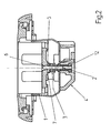
- prinziphaft ein fertig montiertes elektrisches Installationsgerät gemäß Fig. 1;
- Fig. 3:
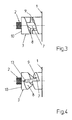
- prinziphaft das Sicherungselement mit Wirkfläche in Zuordnung zur Gegenfläche des ersten Gehäuseteiles gemäß erstem Ausführungsbeispiel in vergrößerter Darstellung;
- Fig. 4:
- prinziphaft das Sicherungselement mit Wirkfläche in Zuordnung zur Gegenfläche des ersten Gehäuseteiles gemäß zweitem Ausführungsbeispiel in vergrößerter Darstellung.
- Wie aus den Figuren hervorgeht, besteht ein solches elektrisches Installationsgerät im Wesentlichen aus einem ersten Gehäuseteil 1, welches über ein als Schraube ausgebildetes Befestigungselement 2 unter Zwischenschaltung eines Sicherungselementes 3 mit einem weiteren Gehäuseteil 4 verbunden werden kann.
- Wie insbesondere aus Fig. 1, Fig. 2 und Fig. 3 hervorgeht ist das als Schraube ausgebildete Befestigungselement 2 drehbeweglich in einer Schraubenaufnahme 5 des ersten Gehäuseteiles 1 gehalten, wobei der Schraubenkopf 6 von der Oberseite des ersten Gehäuseteiles 1 zugänglich ist. Den Schaft 7 ringförmig umgebend ist an der Unterseite des ersten Gehäuseteiles 1 ein mit der zugeordneten ersten Wirkfläche 8 des Sicherungselementes 3 in Anlage kommende Gegenfläche 9 angeformt, die schraubenflächenartig ausgebildet ist. Die zugeordnete erste Wirkfläche 8 des Sicherungselementes 3 ist ebenfalls schraubenflächenartig ausgebildet, wohingegen die zweite Wirkfläche 10 des Sicherungselementes 3 und die zugeordnete Gegenfläche 11 des weiteren Gehäuseteiles 4 jeweils als glatte Ringflächen ausgeführt sind. In Bezug auf die Erstreckungsrichtung der Schraube sind sowohl die Wirkflächen 8, 10 des Sicherungselementes 3, als auch die Gegenflächen 9, 11 des ersten Gehäuseteiles 1 und des weiteren Gehäuseteiles 4 rechtwinkelig verlaufend angeordnet.
- Um einen für die korrekte Funktion weitestgehend drehfesten Sitz des ringförmigen Sicherungselementes 3 auf dem Schaft 7 der Schraube zu gewährleisten, besteht zwischen dem Schaft 7 und der Durchtrittsöffnung des Sicherungselementes 3 eine Presspassung. Die Presspassung ist als leichte Presspassung ausgeführt, so dass beim Einwirken von Drehkräften bestimmter Größenordnungen ein Verdrehen des Sicherungselementes 3 auf dem Schaft 7 möglich ist. Um eine sichere Verbindung des ersten Gehäuseteiles 1 und des weiteren Gehäuseteiles 4 zu gewährleisten, befindet sich unterhalb der Gegenfläche 11 des weiteren Gehäuseteiles 4 ein auf das als Schraube ausgebildete Befestigungselement 2 abgestimmtes, eingeformtes Gewindegegenstück 12.
- Beim Herstellen der Schraubverbindung kommt zunächst die zweite Wirkfläche 10 des Sicherungselementes 3 an der zugehörigen Gegenfläche 11 des weiteren Gehäuseteiles 4 zur Anlage. Dann wird die erste Wirkfläche 8 des Sicherungselementes 3 mehr und mehr der Gegenfläche 9 des ersten Gehäuseteiles 1 zugeordnet. Letztendlich kommen geringe Flächenanteile der ersten Wirkfläche 8 an geringe Flächenanteile der Gegenfläche 9 zur Anlage und bei Drehung der Schraube gleicht die schraubenflächenartige Wirkflächen 8 im Zusammenspiel mit der schraubenflächenartigen Gegenfläche 9 die Distanz zwischen dem ersten Gehäuseteil 1 und dem weiteren Gehäuseteil 4 aus. Wird jetzt durch Drehung der Schraube die Schraubverbindung weiter festgezogen, um einen sicheren Sitz der beiden Gehäuseteile 1, 4 zu gewährleisten, verspannt sich das Sicherungselement 3 gegen die Gegenfläche 9 und gleicht damit sowohl Fertigungstoleranzen der beiden Gehäuseteile 1, 4 als auch dem Einbauort zuzurechnende Einbautoleranzen (Tapetenausgleich, Putzausgleich usw.) automatisch aus. Das erste Gehäuseteil 1 wird somit über die Schraubverbindung spannungsfrei dem weiteren Gehäuseteil 4 zugeordnet, so dass es auch bei größeren Toleranzen nicht zu Beschädigungen an einem der beiden Gehäuseteile 1, 4, bedingt durch das Festziehen der Schraubverbindung kommt.
- Wie insbesondere aus Fig. 4 hervorgeht, weist das Sicherungselement 3 eine in Bezug auf die Erstreckungsrichtung des als Schraube ausgebildeten Befestigungselementes 2 gekippt (ca. 45°) angeordnete Wirkfläche 8 auf, die einer entsprechend gekippt (ca. 45°) angeordneter Gegenfläche 9 des ersten Gehäuseteiles 1 zugeordnet ist. Die zweite Wirkfläche 10 des Sicherungselementes 3 und die zugeordnete Gegenfläche 11 des weiteren Gehäuseteiles 4 sind jeweils als glatte Ringflächen ausgeführt. Das Sicherungselement 3 weist zwei in Erstreckungsrichtung der Schraube verlaufende Schlitze 13 auf. Die Schlitze 13 bewirken, dass das Sicherungselement 3 mit zunehmendem Festziehen des als Schraube ausgebildeten Befestigungselementes 2 mehr und mehr an den Schaft 7 angepresst wird.. Das Einstellen der notwendigen Presspassung zwischen dem Sicherungselement 3 und dem Schaft 7 wird somit stark erleichtert. Im übrigen gilt das was vorstehend bereits zu Fig. 1, Fig. 2 und Fig. 3 ausgeführt wurde.
- Selbstverständlich kann die Schraube auch durch ein andersartig ausgebildetes drehbares Befestigungselement 2, wie z. B. den Schnellbefestigungsstift eines Bajonettverschlusses ersetzt werden, ohne dass der erfinderische Gedanke verlassen wird.
Claims (10)
- Elektrisches Installationsgerät mit einem ersten Gehäuseteil (1) an dem ein Befestigungselement durch ein scheibenförmiges Sicherungselement (3) unverlierbar in einer Aufnahme (5) drehbeweglich gehalten ist, wobei das erste Gehäuseteil (1) über das Befestigungselement mit zumindest einem weiteren Gehäuseteil (1) verbindbar ist, welches ein entsprechendes Befestigungsgegenstück (12) aufweist, dadurch gekennzeichnet, dass das Sicherungselement (3) am Schaft (7) des Befestigungselementes (2) gehalten, und dass zumindest eine seiner beiden gegenüberliegend vorhandenen Wirkflächen (8, 10) schraubenflächenartig ausgeführt ist, und dass zumindest eine zugeordnete Gegenfläche (9, 11) des ersten Gehäuseteiles (1) und/oder des weiteren Gehäuseteiles (4) ebenfalls eine schraubenflächenartige Ausbildung aufweist.
- Elektrisches Installationsgerät nach Anspruch 1, dadurch gekennzeichnet, dass beide gegenüberliegend vorhandenen Wirkflächen (8, 10) des Sicherungselementes (3) schraubenflächenartig ausgeführt sind, und dass sowohl die zugeordnete Gegenfläche (9) des ersten Gehäuseteiles (1) als auch die zugeordnete Gegenfläche (11) des weiteren Gehäuseteiles (4) ebenfalls schraubenflächenartig ausgebildet sind.
- Elektrisches Installationsgerät nach einem der Ansprüche 1 oder 2, dadurch gekennzeichnet, dass das Sicherungselement (3) zumindest eine in Bezug auf die Erstreckungsrichtung des Befestigungselementes (2), im Winkel von 90° angeordnete Wirkfläche (8, 10) aufweist.
- Elektrisches Installationsgerät nach einem der Ansprüche 1 bis 3, dadurch gekennzeichnet, dass das Sicherungselement (3) zumindest eine in Bezug auf die Erstreckungsrichtung des Befestigungselementes (2) gekippt angeordnete Wirkfläche (8, 10) aufweist, und dass die zugeordnete Gegenfläche (9, 11) des ersten Gehäuseteiles (1) und/oder des weiteren Gehäuseteiles (4) entsprechend gekippt ausgeführt ist.
- Elektrisches Installationsgerät nach einem der Ansprüche 1 bis 4, dadurch gekennzeichnet, dass das Sicherungselement (3) zumindest einen in Erstreckungsrichtung des Befestigungselementes (2) verlaufenden Schlitz (13) aufweist.
- Elektrisches Installationsgerät nach einem der Ansprüche 1 bis 5, dadurch gekennzeichnet, dass das Sicherungselement (3) drehfest am Schaft (7) des Befestigungselementes (2) gehalten ist.
- Elektrisches Installationsgerät nach einem der Ansprüche 1 bis 6, dadurch gekennzeichnet, dass das erste Gehäuseteil (1) als Zentralplatte und das weitere Gehäuseteil (4) als Sockel einer Schutzkontaktsteckdose ausgebildet ist.
- Elektrisches Installationsgerät nach einem der Ansprüche 1 bis 6, dadurch gekennzeichnet, dass das erste Gehäuseteil (1) Bestandteil eines Funktionseinsatzes, und dass das weitere Gehäuseteil (4) als entsprechende Funktionsabdeckung ausgebildet ist.
- Elektrisches Installationsgerät nach einem der Ansprüche 1 bis 8, dadurch gekennzeichnet, dass das Befestigungselement (2) als Schraube ausgeführt ist.
- Elektrisches Installationsgerät nach einem der Ansprüche 1 bis 8, dadurch gekennzeichnet, dass das Befestigungselement (2) als Schnellbefestigungsstift eines Bajonettverschlusses ausgeführt ist.
Applications Claiming Priority (1)
| Application Number | Priority Date | Filing Date | Title |
|---|---|---|---|
| DE200410043091 DE102004043091B3 (de) | 2004-09-07 | 2004-09-07 | Elektrisches Installationsgerät |
Publications (2)
| Publication Number | Publication Date |
|---|---|
| EP1633027A1 EP1633027A1 (de) | 2006-03-08 |
| EP1633027B1 true EP1633027B1 (de) | 2007-01-10 |
Family
ID=35070710
Family Applications (1)
| Application Number | Title | Priority Date | Filing Date |
|---|---|---|---|
| EP20050012615 Expired - Lifetime EP1633027B1 (de) | 2004-09-07 | 2005-06-13 | Elektrisches Installationsgerät |
Country Status (2)
| Country | Link |
|---|---|
| EP (1) | EP1633027B1 (de) |
| DE (2) | DE102004043091B3 (de) |
Family Cites Families (3)
| Publication number | Priority date | Publication date | Assignee | Title |
|---|---|---|---|---|
| DE3909236A1 (de) * | 1989-03-21 | 1990-09-27 | Wilfried Boldt | Ein- oder mehrpolige steckdose und/oder schalter fuer die elektroinstallation mot ortsvariablem kontakttraeger bei festinstalliertem steckdosen- und/oder schaltereinsatz |
| DE19709489A1 (de) * | 1997-03-07 | 1998-09-10 | Abb Patent Gmbh | Abdeckung für elektrische Installationsgeräte |
| DE10013032C2 (de) * | 2000-03-17 | 2002-01-17 | Elso Gmbh Elektrotechnik | Elektrische Steckdose |
-
2004
- 2004-09-07 DE DE200410043091 patent/DE102004043091B3/de not_active Expired - Fee Related
-
2005
- 2005-06-13 EP EP20050012615 patent/EP1633027B1/de not_active Expired - Lifetime
- 2005-06-13 DE DE200550000306 patent/DE502005000306D1/de not_active Expired - Lifetime
Also Published As
| Publication number | Publication date |
|---|---|
| DE102004043091B3 (de) | 2005-11-03 |
| DE502005000306D1 (de) | 2007-02-22 |
| EP1633027A1 (de) | 2006-03-08 |
Similar Documents
| Publication | Publication Date | Title |
|---|---|---|
| EP2054977B1 (de) | Steckverbinder für vorderwandmontage oder hinterwandmontage | |
| EP3586415B1 (de) | Steckerkupplung mit zugentlastung für ein verbindungskabel | |
| DE4409612C2 (de) | Elektrische Vorrichtung zum Verbinden elektrischer Leiter, insbesondere Reihenklemme | |
| DE2929222C2 (de) | Höhenverstellbarer Standfuß für Waschmaschinen, Wäschetrockner, Geschirrspülmaschinen und dgl. | |
| EP1269564A1 (de) | Vorrichtung zur befestigung einer fahrzeugantenne | |
| DE212023000086U1 (de) | Dachziegelhaken und Klemmvorrichtung für diesen | |
| DE102019104558B4 (de) | Steckverbinderteil mit einer Rasteinrichtung | |
| EP1633027B1 (de) | Elektrisches Installationsgerät | |
| EP1535371B1 (de) | Durchführungsklemme | |
| EP0615073B1 (de) | Kombination aus Schraubenmutter und Lochscheibe | |
| EP2850983B1 (de) | Duschabtrennung | |
| DE29720772U1 (de) | Abstandshalter für Leiterplatten | |
| DE69904788T2 (de) | Kontaktklammer, insbesondere geeignet für Sammelschienensysteme | |
| DE10114855A1 (de) | Sanitäre Auslaufarmatur | |
| DE20213780U1 (de) | Bus-Gehäuse und Einsatzstücke für die Kabeleinlassöffnungen des Bus-Gehäuses | |
| EP1371530B1 (de) | Befestigungseinrichtung | |
| DE102019101050A1 (de) | Zugentlastung für ein Haushaltsgerät zur Klemmung eines Kabels des Haushaltsgeräts | |
| DE3829030A1 (de) | Verstellbare riegelvorrichtung | |
| EP4153017B1 (de) | Behälteraufnahmevorrichtung und halterung hierzu | |
| EP1154534B1 (de) | Elektro-Installationsgerät | |
| DE3525189C2 (de) | ||
| DE10301879B3 (de) | Steckvorrichtungselement mit Montagegewinde | |
| DE2817469C2 (de) | Montageelement für die Befestigung von Drucktastern, Leuchtmeldern o.dgl. an einer Befestigungsplatte | |
| EP0730839A1 (de) | Befestigungsvorrichtung für einen Badewannengriff oder dergleichen | |
| EP0863582A1 (de) | Abdeckung für elektrische Installationsgeräte |
Legal Events
| Date | Code | Title | Description |
|---|---|---|---|
| PUAI | Public reference made under article 153(3) epc to a published international application that has entered the european phase |
Free format text: ORIGINAL CODE: 0009012 |
|
| AK | Designated contracting states |
Kind code of ref document: A1 Designated state(s): AT BE BG CH CY CZ DE DK EE ES FI FR GB GR HU IE IS IT LI LT LU MC NL PL PT RO SE SI SK TR |
|
| AX | Request for extension of the european patent |
Extension state: AL BA HR LV MK YU |
|
| 17P | Request for examination filed |
Effective date: 20060510 |
|
| GRAP | Despatch of communication of intention to grant a patent |
Free format text: ORIGINAL CODE: EPIDOSNIGR1 |
|
| GRAS | Grant fee paid |
Free format text: ORIGINAL CODE: EPIDOSNIGR3 |
|
| AKX | Designation fees paid |
Designated state(s): AT BE BG CH CY CZ DE DK EE ES FI FR GB GR HU IE IS IT LI LT LU MC NL PL PT RO SE SI SK TR |
|
| GRAA | (expected) grant |
Free format text: ORIGINAL CODE: 0009210 |
|
| AK | Designated contracting states |
Kind code of ref document: B1 Designated state(s): AT BE BG CH CY CZ DE DK EE ES FI FR GB GR HU IE IS IT LI LT LU MC NL PL PT RO SE SI SK TR |
|
| PG25 | Lapsed in a contracting state [announced via postgrant information from national office to epo] |
Ref country code: NL Free format text: LAPSE BECAUSE OF FAILURE TO SUBMIT A TRANSLATION OF THE DESCRIPTION OR TO PAY THE FEE WITHIN THE PRESCRIBED TIME-LIMIT Effective date: 20070110 Ref country code: IE Free format text: LAPSE BECAUSE OF FAILURE TO SUBMIT A TRANSLATION OF THE DESCRIPTION OR TO PAY THE FEE WITHIN THE PRESCRIBED TIME-LIMIT Effective date: 20070110 Ref country code: FI Free format text: LAPSE BECAUSE OF FAILURE TO SUBMIT A TRANSLATION OF THE DESCRIPTION OR TO PAY THE FEE WITHIN THE PRESCRIBED TIME-LIMIT Effective date: 20070110 Ref country code: PL Free format text: LAPSE BECAUSE OF FAILURE TO SUBMIT A TRANSLATION OF THE DESCRIPTION OR TO PAY THE FEE WITHIN THE PRESCRIBED TIME-LIMIT Effective date: 20070110 Ref country code: SI Free format text: LAPSE BECAUSE OF FAILURE TO SUBMIT A TRANSLATION OF THE DESCRIPTION OR TO PAY THE FEE WITHIN THE PRESCRIBED TIME-LIMIT Effective date: 20070110 Ref country code: DK Free format text: LAPSE BECAUSE OF FAILURE TO SUBMIT A TRANSLATION OF THE DESCRIPTION OR TO PAY THE FEE WITHIN THE PRESCRIBED TIME-LIMIT Effective date: 20070110 |
|
| REG | Reference to a national code |
Ref country code: GB Ref legal event code: FG4D Free format text: NOT ENGLISH |
|
| REG | Reference to a national code |
Ref country code: IE Ref legal event code: FG4D Free format text: LANGUAGE OF EP DOCUMENT: GERMAN |
|
| REF | Corresponds to: |
Ref document number: 502005000306 Country of ref document: DE Date of ref document: 20070222 Kind code of ref document: P |
|
| PG25 | Lapsed in a contracting state [announced via postgrant information from national office to epo] |
Ref country code: SE Free format text: LAPSE BECAUSE OF FAILURE TO SUBMIT A TRANSLATION OF THE DESCRIPTION OR TO PAY THE FEE WITHIN THE PRESCRIBED TIME-LIMIT Effective date: 20070410 Ref country code: BG Free format text: LAPSE BECAUSE OF FAILURE TO SUBMIT A TRANSLATION OF THE DESCRIPTION OR TO PAY THE FEE WITHIN THE PRESCRIBED TIME-LIMIT Effective date: 20070410 |
|
| PG25 | Lapsed in a contracting state [announced via postgrant information from national office to epo] |
Ref country code: ES Free format text: LAPSE BECAUSE OF FAILURE TO SUBMIT A TRANSLATION OF THE DESCRIPTION OR TO PAY THE FEE WITHIN THE PRESCRIBED TIME-LIMIT Effective date: 20070421 |
|
| PG25 | Lapsed in a contracting state [announced via postgrant information from national office to epo] |
Ref country code: IS Free format text: LAPSE BECAUSE OF FAILURE TO SUBMIT A TRANSLATION OF THE DESCRIPTION OR TO PAY THE FEE WITHIN THE PRESCRIBED TIME-LIMIT Effective date: 20070510 |
|
| PG25 | Lapsed in a contracting state [announced via postgrant information from national office to epo] |
Ref country code: PT Free format text: LAPSE BECAUSE OF FAILURE TO SUBMIT A TRANSLATION OF THE DESCRIPTION OR TO PAY THE FEE WITHIN THE PRESCRIBED TIME-LIMIT Effective date: 20070611 |
|
| NLV1 | Nl: lapsed or annulled due to failure to fulfill the requirements of art. 29p and 29m of the patents act | ||
| GBV | Gb: ep patent (uk) treated as always having been void in accordance with gb section 77(7)/1977 [no translation filed] |
Effective date: 20070110 |
|
| REG | Reference to a national code |
Ref country code: IE Ref legal event code: FD4D |
|
| EN | Fr: translation not filed | ||
| PLBE | No opposition filed within time limit |
Free format text: ORIGINAL CODE: 0009261 |
|
| STAA | Information on the status of an ep patent application or granted ep patent |
Free format text: STATUS: NO OPPOSITION FILED WITHIN TIME LIMIT |
|
| PG25 | Lapsed in a contracting state [announced via postgrant information from national office to epo] |
Ref country code: GB Free format text: LAPSE BECAUSE OF FAILURE TO SUBMIT A TRANSLATION OF THE DESCRIPTION OR TO PAY THE FEE WITHIN THE PRESCRIBED TIME-LIMIT Effective date: 20070110 Ref country code: SK Free format text: LAPSE BECAUSE OF FAILURE TO SUBMIT A TRANSLATION OF THE DESCRIPTION OR TO PAY THE FEE WITHIN THE PRESCRIBED TIME-LIMIT Effective date: 20070110 |
|
| 26N | No opposition filed |
Effective date: 20071011 |
|
| BERE | Be: lapsed |
Owner name: ALBRECHT JUNG G.M.B.H. & CO. KG Effective date: 20070630 |
|
| PG25 | Lapsed in a contracting state [announced via postgrant information from national office to epo] |
Ref country code: CZ Free format text: LAPSE BECAUSE OF FAILURE TO SUBMIT A TRANSLATION OF THE DESCRIPTION OR TO PAY THE FEE WITHIN THE PRESCRIBED TIME-LIMIT Effective date: 20070110 Ref country code: RO Free format text: LAPSE BECAUSE OF FAILURE TO SUBMIT A TRANSLATION OF THE DESCRIPTION OR TO PAY THE FEE WITHIN THE PRESCRIBED TIME-LIMIT Effective date: 20070110 |
|
| PG25 | Lapsed in a contracting state [announced via postgrant information from national office to epo] |
Ref country code: MC Free format text: LAPSE BECAUSE OF NON-PAYMENT OF DUE FEES Effective date: 20070630 |
|
| PG25 | Lapsed in a contracting state [announced via postgrant information from national office to epo] |
Ref country code: BE Free format text: LAPSE BECAUSE OF NON-PAYMENT OF DUE FEES Effective date: 20070630 Ref country code: LT Free format text: LAPSE BECAUSE OF FAILURE TO SUBMIT A TRANSLATION OF THE DESCRIPTION OR TO PAY THE FEE WITHIN THE PRESCRIBED TIME-LIMIT Effective date: 20070110 |
|
| PG25 | Lapsed in a contracting state [announced via postgrant information from national office to epo] |
Ref country code: GR Free format text: LAPSE BECAUSE OF FAILURE TO SUBMIT A TRANSLATION OF THE DESCRIPTION OR TO PAY THE FEE WITHIN THE PRESCRIBED TIME-LIMIT Effective date: 20070411 Ref country code: IT Free format text: LAPSE BECAUSE OF FAILURE TO SUBMIT A TRANSLATION OF THE DESCRIPTION OR TO PAY THE FEE WITHIN THE PRESCRIBED TIME-LIMIT Effective date: 20070110 Ref country code: FR Free format text: LAPSE BECAUSE OF FAILURE TO SUBMIT A TRANSLATION OF THE DESCRIPTION OR TO PAY THE FEE WITHIN THE PRESCRIBED TIME-LIMIT Effective date: 20070831 |
|
| PG25 | Lapsed in a contracting state [announced via postgrant information from national office to epo] |
Ref country code: AT Free format text: LAPSE BECAUSE OF NON-PAYMENT OF DUE FEES Effective date: 20070613 |
|
| PG25 | Lapsed in a contracting state [announced via postgrant information from national office to epo] |
Ref country code: FR Free format text: LAPSE BECAUSE OF FAILURE TO SUBMIT A TRANSLATION OF THE DESCRIPTION OR TO PAY THE FEE WITHIN THE PRESCRIBED TIME-LIMIT Effective date: 20070110 |
|
| PG25 | Lapsed in a contracting state [announced via postgrant information from national office to epo] |
Ref country code: EE Free format text: LAPSE BECAUSE OF FAILURE TO SUBMIT A TRANSLATION OF THE DESCRIPTION OR TO PAY THE FEE WITHIN THE PRESCRIBED TIME-LIMIT Effective date: 20070110 |
|
| PG25 | Lapsed in a contracting state [announced via postgrant information from national office to epo] |
Ref country code: CY Free format text: LAPSE BECAUSE OF FAILURE TO SUBMIT A TRANSLATION OF THE DESCRIPTION OR TO PAY THE FEE WITHIN THE PRESCRIBED TIME-LIMIT Effective date: 20070110 |
|
| PG25 | Lapsed in a contracting state [announced via postgrant information from national office to epo] |
Ref country code: LU Free format text: LAPSE BECAUSE OF NON-PAYMENT OF DUE FEES Effective date: 20070613 |
|
| PG25 | Lapsed in a contracting state [announced via postgrant information from national office to epo] |
Ref country code: HU Free format text: LAPSE BECAUSE OF FAILURE TO SUBMIT A TRANSLATION OF THE DESCRIPTION OR TO PAY THE FEE WITHIN THE PRESCRIBED TIME-LIMIT Effective date: 20070711 Ref country code: TR Free format text: LAPSE BECAUSE OF FAILURE TO SUBMIT A TRANSLATION OF THE DESCRIPTION OR TO PAY THE FEE WITHIN THE PRESCRIBED TIME-LIMIT Effective date: 20070110 |
|
| REG | Reference to a national code |
Ref country code: CH Ref legal event code: PL |
|
| PG25 | Lapsed in a contracting state [announced via postgrant information from national office to epo] |
Ref country code: CH Free format text: LAPSE BECAUSE OF NON-PAYMENT OF DUE FEES Effective date: 20090630 Ref country code: LI Free format text: LAPSE BECAUSE OF NON-PAYMENT OF DUE FEES Effective date: 20090630 |
|
| PGFP | Annual fee paid to national office [announced via postgrant information from national office to epo] |
Ref country code: DE Payment date: 20130422 Year of fee payment: 9 |
|
| REG | Reference to a national code |
Ref country code: DE Ref legal event code: R119 Ref document number: 502005000306 Country of ref document: DE |
|
| REG | Reference to a national code |
Ref country code: DE Ref legal event code: R119 Ref document number: 502005000306 Country of ref document: DE Effective date: 20150101 |
|
| PG25 | Lapsed in a contracting state [announced via postgrant information from national office to epo] |
Ref country code: DE Free format text: LAPSE BECAUSE OF NON-PAYMENT OF DUE FEES Effective date: 20150101 |